Advanced Krypton Fluoride Excimer Laser for ... - Cymer
Advanced Krypton Fluoride Excimer Laser for ... - Cymer
Advanced Krypton Fluoride Excimer Laser for ... - Cymer

Create successful ePaper yourself
Turn your PDF publications into a flip-book with our unique Google optimized e-Paper software.
<strong>Advanced</strong> <strong>Krypton</strong> <strong>Fluoride</strong> <strong>Excimer</strong> <strong>Laser</strong> <strong>for</strong><br />
Microlithography<br />
Toshihiko Ishihara, Richard Sandstrom,<br />
.<br />
Christopher Reiser, Uday Sengupta<br />
<strong>Cymer</strong> <strong>Laser</strong> Technologies, Inc., 16275 Technologies Drive, SanDiego, CA 92127<br />
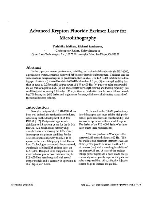
Abstract<br />
In this paper, we present per<strong>for</strong>mance, reliability, and maintainability data <strong>for</strong> the ELS-4000,<br />
a production-worthy, spectrally narrowed KrF excimer laser <strong>for</strong> wafer steppers. This laser uses the<br />
same modular design concept as its predecessor, the CX-2LS. The ELS-4000 exhibits the following<br />
specifications: (i) spectral bandwidth (FWHM) less than 2.0 pm; (ii) wavelength stability less<br />
than or equal to 0.25 pm; (iii) output power of 4 W at 400 Hz; (iv) pulse-to-pulse energy stability<br />
less than or equal to 2.5%; (v) fast and accurate wavelength slewing and locking capability; (vi)<br />
small footprint measuring 0.74 m by 1.36 m; (vii) mean productive time between failures exceeding<br />
700 hours; and (viii) design and engineering features, which meet all the safety standards of<br />
the semiconductor industry.<br />
Introduction<br />
Now that design ofthe 16 Mb DRAM has<br />
been well defined, the semiconductor industry<br />
is focusing on the development of 64 Mb<br />
DRAM. [1,2] Design rules appear to be<br />
shrinking to 0.3 microns or less <strong>for</strong> the 64 Mb<br />
DRAM. As a result, many memory chip<br />
manufacturers are choosing the KrF excimer<br />
laser stepper as a primary candidate <strong>for</strong> the<br />
next-generation lithography tool.[3] In response<br />
to this microlithography trend, <strong>Cymer</strong><br />
<strong>Laser</strong> Technologies developed a line-narrowed,<br />
wavelength-stabilized KrF excimer laser, the<br />
ELS-4000. Designed to be compatible with<br />
semiconductor production environments, the<br />
ELS-4000 has been integrated with several<br />
stepper models, and is currently in operation in<br />
U.S., Japan, and Korea.<br />
To be used in the DRAM production, a<br />
laser lithography tool must exhibit high per<strong>for</strong>mance,<br />
good reliability and maintainability, and<br />
low cost ofoperation - all in a small footprint.<br />
The design ofthe ELS-4000 Series of excimer<br />
lasers meets these requirements.<br />
This laser produces 4 W of spectrallynarrowed<br />
248 nm radiation at 400 Hz. The<br />
full width at halfmaximum intensity (FWHM)<br />
of the spectral profile measures less than 2.0<br />
picometers (pm) with a wavelength stability of<br />
less than 0.25 pm. A state-of-the-art high<br />
voltage power supply and a burst-mode energy<br />
control algorithm greatly improve the pulse-topulse<br />
energy stability. Also, a fluorine injection<br />
scheme helps to increase the gas life.<br />
O8 1 94-0829-8/92/$4.OO SPIE Vol. 1674 Optical/<strong>Laser</strong> Microlithography V (1992) / 473
The ELS-4000 is currently undergoing<br />
extensive testing to determine long-term<br />
per<strong>for</strong>mance stability and establish accurate<br />
maintenance cycles. In addition, we are monitoring<br />
the per<strong>for</strong>mance ofall systems in the<br />
field to measure reliability and uptime per<strong>for</strong>mance.<br />
In this paper, we will describe the ELS-<br />
4000 system and present its per<strong>for</strong>mance and<br />
specification data, life test program, and most<br />
recent improvements. Finally, we will discuss<br />
the reliability and maintainability ofthe system.<br />
127mm<br />
(Sin)<br />
(3.25in±L2Ssn)<br />
Fgure 1. The physical specfi cation of the ELS -4000 laser<br />
reveals its small footprint - approximately one square<br />
meter (11.1 sqft).<br />
ESL-4000 system<br />
description:<br />
The ELS-4000 occupies a small floor<br />
space, as shown in the physical specification in<br />
Figure 1. Its footprint covers approximately<br />
one square meter (11.1 sq ft). One side provides<br />
access <strong>for</strong> most of maintenance services,<br />
except <strong>for</strong> utility connections. <strong>Laser</strong> gases, dry<br />
nitrogen, and cooling water connect to a single<br />
utility box located at the rear-left corner. The<br />
exhaust duct connects directly to the utility<br />
box to ensure gas safety. Table 1 shows typical<br />
utilities consumption.<br />
The ELS-4000 uses the same modular<br />
design concept as its predecessor, the CX-2LS,<br />
Table 1: Typical Utilities Consumption<br />
Power: 3 phase, 2O8Vac ( 190 mm, 220 max), 11A(rms)<br />
Cooling water: 6 1/mm, 15-20°C<br />
Gas Purity Usage<br />
0.9-1.0% F2 in Ne F2 99.9% 9 liter-atm per l07shots<br />
Ne 99.999%<br />
1.2-1.3% Kr in Ne Kr 99.999% 60 liter-atm per fill<br />
Ne 99.999%<br />
Helium 99.999% 300 liter-atm per window change<br />
Nitrogen 99.995% 200 liter/hour<br />
boil-off liquid nitrogen is recommended<br />
474 / SPIE Vol. 1674 Optical/<strong>Laser</strong> Microlithography V (1992)
LINE—NARROWING<br />
MODULE<br />
PULSE POWER<br />
MODULE<br />
/<br />
48<br />
BLOWER POWER<br />
SUPPLY<br />
WAVEMETER<br />
MODULE<br />
OUTPUT<br />
END<br />
CM3 CONTROL<br />
MODULE<br />
VACUUM PUMP..J<br />
OUT MODULE<br />
(VAPO)<br />
HIGH VOLTAGE<br />
POWER SUPPLY<br />
UTILITIES<br />
EMERGENCY OFF<br />
MODULE (EMO)<br />
Fgure 2. The ELS -4000 uses a modular des&n concept<br />
<strong>for</strong> ease of maintenance and safety.<br />
SPIE Vol. 1674 Optical/<strong>Laser</strong> Microlithography V (1992) / 475
Fqure 3. The laser control s,ctem <strong>for</strong> the ELS -4000 system is microprocessor controlled.<br />
<strong>for</strong> ease ofmaintenance and safety. The laser<br />
comprises the major modules shown in Figure<br />
2. The upper part of the laser holds the discharge<br />
chamber, precipitator, pulse power<br />
module, line-narrowing module, output coupler<br />
plate, wavemeter, and 48 V dc power<br />
supply. The lower part contains utility and<br />
supporting modules: the microprocessor<br />
control unit (called CM-3), high-voltage<br />
power supply, gas manifold/utility inlets,<br />
electric power distribution box, and a vacuum<br />
pump unit which includes a fluorine trap.<br />
By resting on rollers, the discharge<br />
chamber rolls out <strong>for</strong> easy servicing. In particular,<br />
users can quickly per<strong>for</strong>m preventive<br />
maintenance, including window cleaning and<br />
replacement, pulse power replacement, and<br />
chamber replacement. Sheet metal completely<br />
encloses the pulse-power module, so no high<br />
voltage is exposed during the operation and<br />
service.<br />
The discharge chamber contains only<br />
fluorine-compatible refractory materials, and<br />
extreme care is taken during cleaning of its<br />
parts and assembly processes. As a result, a<br />
single gas fill runs <strong>for</strong> more than 8 million<br />
shots or 48 hours, whichever comes first, with<br />
fluorine injections. Also, the precipitator on<br />
the discharge chamber works as a dust filter to<br />
help to keep the windows clean, extending the<br />
window cleaning interval to more than 200<br />
million shots. The full maintenance schedule<br />
will appear in a later section.<br />
Figure 3 shows a schematic of the laser<br />
system. Wavelength monitoring and control<br />
476 / SPIE Vol. 1674 Optical/<strong>Laser</strong> Microlithography V (1992)
Table 2: The ELS-4000 Basic Per<strong>for</strong>mance<br />
Rated Power<br />
Repetition Rate<br />
Pulse Energy<br />
Wavelength Tuning Range<br />
Wavelength Stability (with control)<br />
(w/o control)<br />
Spectral Bandwidth<br />
Polarization Ratio<br />
Pulse-to-Pulse Energy Fluctuation<br />
Beam Size (HxV)<br />
Beam Divergence<br />
4W<br />
400 Hz<br />
lOmJ<br />
248.2 to 248.5 nm<br />
1.0<br />
0.8<br />
0.6<br />
a,<br />
0.4<br />
a,<br />
0.2<br />
0.0<br />
-X (pm)<br />
spectral profile has shorter wings than the<br />
Lorentzian. Figure 5 shows a plot of the<br />
integrated spectrum. For this plot, the<br />
spectral profile ofFigure 4 was integrated<br />
from the peak wavelength toward two extremes.<br />
It shows that 95% of the total energy<br />
lies within 2.30 pm band about the peak<br />
wavelength.<br />
Fgure 4. To measure this undeconvolved spectral profile of a<br />
typical ELS-4000 laser output, a high resolution spectrometer<br />
with 0.21 pm resolution was used. The bandwidth (FWHM) is<br />
1.60 pm, and 95% of the total energy is in a 4.60 pm band.<br />
The ELS-4000 laser light exhibits<br />
some variations in wavelength over the beam.<br />
As Sandstrom observed, the beam has a<br />
nearly-linear wavelength shift ofO.59 pm/<br />
mm in the horizontal direction and no wavelength<br />
variation in the vertical direction.[4]<br />
The horizontal variation is a consequence of<br />
the use ofa grating as a line-narrowing<br />
dispersive element. No vertical wavelength<br />
variation exists due to a particular orientatign<br />
ofthe grating.<br />
e<br />
E<br />
0.2<br />
0.1<br />
-0.0<br />
-0.1<br />
-0.2<br />
-:0i (pm)<br />
Fgure 5. This integration ofthe spectrum in Figure 4 shows<br />
that 95% ofthe total energy resides in a 4.6Opm band, 2.30<br />
pm of the center wavelength.<br />
Ui U I I I I I U I I I I I U I I I I U I I I I I I I I I<br />
10 20 30 40<br />
Pulse #<br />
Fqure 6. This wavelength chirping behavior,from a typical<br />
ELS-4000 laser, appears when the laser operates in a burst<br />
mode—one 40-shot burst in every second at 1 0 mJ and 400 Hz.<br />
The ELS-4000 laser has a wavelength<br />
locking capability - once the laser output<br />
wavelength is programmed to lock onto a<br />
certain value it will remain at that wavelength.<br />
The wavelength stability with wavelength<br />
locking measures 0.25 pm. The<br />
output wavelength can be tuned from 248.2<br />
nm to 248.5 nm with tuning speed as fast as<br />
20 pm/sec and with repeatability of± 0.1<br />
pm. The laser exhibits less than 6 pm of<br />
passive wavelength drift over 24 hours in a<br />
constant temperature environment.<br />
During bursts ofshots, the ELS-4000<br />
laser exhibits an initial transient wavelength<br />
drift called "wavelength chirping." The<br />
output wavelengths <strong>for</strong> the first 5 to 10 shots<br />
are likely to differ from the target wavelength<br />
programmed into the laser. Figure 6 shows<br />
the wavelength chirping behavior of a typical<br />
ELS-4000 laser. The first shot has the wavelength<br />
longer than the target by 0.2 pm, and<br />
the second was shorter by 0.1 pm. After<br />
that, the transient decays rapidly. However,<br />
478 / SPIE Vol. 1674 Optical/<strong>Laser</strong> Microlithography V (1992)
Figure 7. This transient behavior of burst<br />
output energy occurs without HV trimming<br />
control. This burst mode produces one 30-shot<br />
burst in every second at 10 mJand 400 Hz.<br />
Figure 8. This example of burst output<br />
energy shows how H Vtrimming control<br />
controls controls transient behavior. Like<br />
Fqure 7, the burst mode fires one 30-shot<br />
burst in everj second at 10 mJ and 400 Hz.<br />
F:gure 9. The vertical beam profile of a<br />
typical ELS-4000 laser, measured at lm<br />
awayfrom the laser, shows the full width at<br />
half maximum points (FWHM) of this beam<br />
at 18.4 mm.<br />
SPIE Vol. 1674 Optical/<strong>Laser</strong> Microlithography V (1992) / 479
the effective bandwidth calculated by integrating<br />
all the spectral profiles ofa 40-shot burst<br />
shown in Figure 6 is 1.70 pm, and the 95%of<br />
energy is in a 2.40 pm band. This result<br />
indicates that the chirping has an insignificant<br />
effect on the stepper per<strong>for</strong>mance.<br />
The ELS-4000 output is polarized<br />
horizontally. The polarization ratio defined as<br />
(H - V)/(H + V), where H stands <strong>for</strong> the<br />
energy in the horizontal polarization component<br />
ofthe beam and V stands <strong>for</strong> the vertical<br />
component, results in a value higher than<br />
90%.[4} The particular direction of the polarization<br />
results from the orientation of the<br />
optics used in the line-narrowing module.<br />
The pulse-to-pulse energy stability<br />
largely determines dose accuracy and the<br />
illumination uni<strong>for</strong>mity over the wafer. To<br />
achieve good pulse-to-pulse energy stability,<br />
the ELS-4000 uses a state-of-the-art highvoltage<br />
power supply, with a regulation of<br />
0.15%. Also, it comes equiped with a sophisticated<br />
energy control software. Together, they<br />
help to keep the standard deviation of the<br />
pulse-to-pulse energy stability below 2.5%,<br />
when the stability is measured over a period of<br />
one minute during the continuous run. The<br />
peak-to-peak energy fluctuation remains within<br />
15%.<br />
However, when the laser operates in<br />
burst mode, it exhibits another transient phenomenon.<br />
Pulse energies <strong>for</strong> a first 5 to 10<br />
shots of a burst are likely to be higher than the<br />
target value, as shown in Figure 7. For this<br />
measurement, the laser fired a burst of 30 shots<br />
every second at 400 Hz. Pulse energies of the<br />
first 5 shots were more than 10% higher than<br />
the target 10 mJ, and after 10 shots the pulse<br />
energy came down close the the target.<br />
To suppress this undesirable transient<br />
phenomenon, <strong>Cymer</strong> developed a new energy<br />
control algorithm called "HV Trimming."<br />
This software's adaptive control scheme uses<br />
previous bursts' energy and high-voltage<br />
in<strong>for</strong>mation to calculate charging voltages that<br />
will keep the first few shots close to the target<br />
output energy. Figure 8 shows a pulse-to-pulse<br />
energy variation of the same laser with HV<br />
trimming control engaged, clearly demonstrating<br />
suppression ofthe initial transient. This<br />
new energy control software should help in<br />
obtaining an efficient and repeatable illumination<br />
over die sites at the wafer.<br />
The beam size is approximately 5 x 18<br />
mm2 (H x V) in FWHM when measured at im<br />
away from the laser. The beam size may varies<br />
within depending on the conditions of<br />
laser gas and discharge chamber. Figures 9 and<br />
10 show typical beam profiles in vertical and.<br />
horizontal directions respectively, as measured<br />
by a linear photodiode array of 1024 elements.<br />
The vertical profile is a quasi-top-hat, and the<br />
horizontal profile is approximately Gaussian.<br />
The beam dimension is primary determined by<br />
the size of the discharge, the internal aperature,<br />
and the divergence.<br />
The divergence is typically less than 4<br />
mR in both directions when measured using a<br />
f=lm lens. Figures 11 and 12 show divergence<br />
of a typical beam in vertical and horizontal<br />
directions respectively. Smallest spots were<br />
searched to discover the divergence due to the<br />
modes of higher order, whereas the divergence<br />
measured exactly at the focal length of a Fourier<br />
trans<strong>for</strong>ming lens is a measurement of the<br />
zeroth order contribution to the divergence.<br />
The vertical divergence was found to be 2.13<br />
mR, and the horizontal was 1.63 mR. A slight<br />
asymmetricity of the vertical beam divergence<br />
profile is a reflection of the vertical profile<br />
which is also slightly asymmetrical (see Figure<br />
9).<br />
480/ SPIE Vol. 1674 Optical/<strong>Laser</strong> Microlithography V (1992)
Fgure 10. The horizontal beam profile<br />
of a typical ELS-4000 laser, measured<br />
at 1 m away from the laser, shows the<br />
full width at half maximum points<br />
(FWHM) of this beam at 4.7 mm.<br />
Fqure 11. This vertical divergence of a<br />
beam in Figure 9 shows the full angle<br />
at lie points of this divergence<br />
measurement at 2.13 mRad. The<br />
divergence was measured using af=lm<br />
lens.<br />
Fgure 12. The horizontal divergence of<br />
a beam in Fgure 10 shows the full<br />
angle at l/e points of this divergence<br />
measurement at 1.63 mRad. The<br />
divergence was measured using af=lm<br />
lens.<br />
SPIE Vol. 1674 Optical/<strong>Laser</strong> Microlithography V (1992)1481
Life test program and<br />
Recent development<br />
During the past year, <strong>Cymer</strong> initiated a<br />
Life Test program to improve the ELS-4000<br />
laser. The program aims to determine several<br />
key aspects of the per<strong>for</strong>mance and cost basis<br />
ofthe ELS-4000 laser system, including:<br />
• life times ofmajor components,<br />
• preventive maintenance schedules,<br />
• costs of long-term operation, and<br />
• longevity improvement of new design<br />
features.<br />
To date the program has consisted of<br />
running two ELS-4000 lasers five days per<br />
week, 23 hours per day. To simulate the duty<br />
that a laser would experience on an actual<br />
stepper, we set the lasers to fire a repetitive<br />
program of one second on, one second off.<br />
Pulse energy was locked at 10 mJ at a 400 Hz<br />
repetition rate. Strip chart recorders continuously<br />
monitored laser charging voltage and<br />
bandwidth. Technicians manually recorded the<br />
lasers' progress on a daily basis, while a computer<br />
downloaded and saved laser status data<br />
every hour. Other parameters, such as beam<br />
size and divergence, were measured on a<br />
weekly basis.<br />
In this manner, approximately 80<br />
million shots could be accumulated on each<br />
unit per week, while gradual trends in laser<br />
per<strong>for</strong>mance could be tracked by plotting the<br />
daily and weekly data. As ofFebruary 1, 1992,<br />
one of the life test lasers delivered more than<br />
2.6 x lO9pulses accumulated over 350 days.<br />
During the program, we redesigned<br />
some modules including the discharge chamber<br />
and the pulse-power module. The electrodes<br />
shapes were changed <strong>for</strong> better control the<br />
discharge profile and gain distribution over<br />
many shots. As a result, the discharge chamber<br />
achieves a stable output <strong>for</strong> more than 10<br />
shots. The pulse powers exhibited some variations<br />
in their per<strong>for</strong>mance, apparently caused<br />
by the thyratron manufacturing process. By<br />
working closely with the thyratron manufacture,<br />
the variation in thyratron characteristics is<br />
now greatly reduced, and the laser per<strong>for</strong>mance<br />
Table 3: Preventive maintenance schedule<br />
Item<br />
Gas exchange:<br />
Window:<br />
Output coupler:<br />
Output window:<br />
F2 trap replacement:<br />
Pump oil replacement:<br />
Maintenance interval<br />
8 x 10⁶ shots or 48 Hours,<br />
whichever comes first.<br />
200 x 106 shots<br />
600 x 106 shots<br />
600 x 106 shots<br />
250 refill cycles<br />
10 or 1 year 2 hour<br />
Time Required'<br />
15 minutes<br />
1 hour2<br />
1 hour3<br />
30 minute4<br />
2 hour<br />
' Time required to per<strong>for</strong>m the service and bring the laser back to operational condition.<br />
2 Inspect <strong>for</strong> cleanliness. Clean or replace only ifwindows are dirty.<br />
3 Inspect <strong>for</strong> coating damage. Replace only if coatings are damaged.<br />
4 Inspect <strong>for</strong> coating damage. Replace only if coatings are damaged. Purging of the outer<br />
surface with clean nitrogen, i.e. boil-offliquid N2 will help to extend the life ofan output<br />
window.<br />
482 / SPIE Vol. 1674 Optical/<strong>Laser</strong> Microlithography V (1992)
Table 4: Module lifetime<br />
Module Lifetime Time to replace'<br />
Discharge chamber 600 x 106 shots (109)* 8 hours<br />
Pulse power module 10 shots (3 x 109)* 2 hour<br />
Wavemeter module 3 x 10 shots 4 hours<br />
Line-narrowing module 3 x 10 shots 4 hours<br />
'Time required to replace the module and adjust the laser to bring the laser back to<br />
-<br />
completely operational condition.<br />
+ Minimum life.<br />
*<br />
<strong>Laser</strong>s and spare parts manufactured after July 1992 are expected to achieve those lifetime.<br />
equipment<br />
downtime<br />
+<br />
uptime<br />
1<br />
NON-SCHEDULED<br />
UNSCHEDULED<br />
DOWNTIME<br />
SCHEDULED<br />
DOWTIME<br />
PRODUCTWE<br />
STANDBY<br />
Fgure 13. These equipment states are defined by SEMI E1O-90 Guideline <strong>for</strong> definition and<br />
measurement of equipment reliability, availability, and maintainability (RAM).<br />
A<br />
Operations<br />
time<br />
total time<br />
(8760 hrs/yr)<br />
has also improved.<br />
The improved modules have been<br />
tested and proven to per<strong>for</strong>m to expectations.<br />
Feedback from the lifetest program is continuously<br />
given to the engineering improvement<br />
program, and the per<strong>for</strong>mance and reliability of<br />
the ELS-4000 system is improving day by day.<br />
The lifetime of major components,<br />
preventive maintenance schedule and reliability<br />
will be described in the following section.<br />
Reliability and<br />
maintainability<br />
The ELS-4000 uses a modular design<br />
concept so that most maintenance services<br />
require simply replacing modules without<br />
disturbing other part ofthe laser. We have<br />
compiled the lifetest results to determine the<br />
preventive maintenance schedule and time to<br />
per<strong>for</strong>m services. Table 3 shows the scheduled<br />
preventive maintenance, and Table 4 shows the<br />
SPIE Vol. 1674 Optical/<strong>Laser</strong> Microlithography V (1992)! 483
Table 5: RAM figures calculated in Sept. 1991,<br />
using data of 16 ELS-4000 lasers<br />
Productive Shots<br />
Operations Time<br />
Total Equipment Downtime<br />
Productive Time<br />
Equipment Uptime<br />
Downtime Incidents<br />
Total Time<br />
MPTBF (Mean Productive Time Between Failures)<br />
MPTBA (Mean Productive Time Between Assists)<br />
Equipment-dependent uptime %<br />
Supplier-dependent uptime %<br />
Operational uptime %<br />
MTTR (Mean Time to Repair)<br />
MTOL (Mean Time Off Line)<br />
Operational utilization %<br />
Total Utilization %<br />
MPBF (Mean Pulses Be<strong>for</strong>e Failure)<br />
5.107 x 10 shots<br />
20430.4 hours<br />
1081.74 hours<br />
19348.66 hours<br />
19348.66 hours<br />
616 events<br />
22371.29 hours<br />
744.2 hours<br />
1209.3 hours<br />
98.1 %<br />
94.7%<br />
94.7%<br />
3.9 hours<br />
1.8 hours<br />
94.7%<br />
86.5 %<br />
196.4x 10⁶<br />
Note:<br />
See Ref. 5 <strong>for</strong> detail definitions of RAM figures.<br />
expected lifetime ofmajor modules.<br />
As shown in Table 4, we are also extending<br />
the discharge chamber and pulse<br />
power module life substantially. They were the<br />
key modules identified during the lifetest<br />
program <strong>for</strong> redesign. The redesigning ef<strong>for</strong>ts<br />
extended the discharge chamber life beyond<br />
10 shots and the pulse power to 3 x 1O shots.<br />
The major optics modules, wavemeter and linenarrowing,<br />
have a specified lifetime of 3 x 1O<br />
shots.<br />
The most frequently required maintenance<br />
after gas exchange is window inspection<br />
and cleaning. With the increased efficiency of<br />
the metal fluoride trap (precipitator), the<br />
minimum window cleaning interval is 200 x<br />
106 shots, or 25 gas fills.<br />
Based on the use of2 x l09pulses in<br />
one year, the total time required to per<strong>for</strong>m<br />
the preventive maintenance and module replacements<br />
is calculated to be 1 19.5 hours<br />
including 62.5 hours to exchange laser gas 250<br />
times per 2 x 10 shots. Assuming the 8000<br />
hours of operation time per year, the maximum<br />
operational uptime percentage should be<br />
98.5%, if no unscheduled downtime occurs.<br />
We have calculated reliability, availability<br />
and maintainability (RAM) figures based on<br />
SEMI E10-90 guidelines[5]. Figure 13 shows<br />
the stack of five basic states. Total time (8760<br />
hours per year) is the sum of Operations Time<br />
and Non-Scheduled Time: Operations Time<br />
comprises Equipment Uptime and Equipment<br />
484 / SPIE Vol. 1674 Optical/<strong>Laser</strong> Microlithography V (1992)
Downtime. The descriptions ofdetailed time<br />
allocation categories are self explanatory.<br />
To have a consistent model, we made<br />
certain assumptions to simulate a production<br />
scenario. In a year (8760 hours), we have<br />
assumed that 760 hours will be allotted to nonscheduled<br />
time. The remaining 8000 hours<br />
then correspond to operations time. These<br />
8000 hours ofoperation time would equate to<br />
2 x 1O pulses on the laser, giving us a simple<br />
relationship between number oflaser pulses<br />
and time. Furthermore, we have assumed that<br />
the standby time is zero in our model, there<strong>for</strong>e,<br />
total equipment uptime equals productive<br />
the.<br />
The summary of RAM figures calculated<br />
in September, 1991 based on sixteen<br />
ELS-4000 lasers operating in the field and at<br />
<strong>Cymer</strong> appears in Table 5. For the total number<br />
ofshots accumulated by 16 lasers was<br />
5.107 x 1O shots. The mean time between<br />
failures was calculated to be 744 hours, and the<br />
mean pulses be<strong>for</strong>e failure was 196.4 M shots.<br />
The actual operational uptime percentage is<br />
94.7% - only 3.8% lower than the maximum<br />
possible operational time of98.5%. A high<br />
availability figure of the ELS-4000 should<br />
speak <strong>for</strong> its reliability and maintainability<br />
without further explanations.<br />
safety standards ofthe industry. On-going life<br />
test program resulted in continuous improvement<br />
in system reliability. A high operational<br />
uptime figure proves the maturation of the<br />
ELS-4000.<br />
Bibliography<br />
1: Y. Funaki, et. al., "Development of<br />
64M lithography using phase-shift technology,"<br />
Nikkei Microdevices, Nikkei Business<br />
Publishing, 44 May (1991).<br />
2: Y. Nakagome, et. a!., Proc. Dig. Symp.<br />
VLSI Circuits, 17 (1990).<br />
3: T. Tamada et. al., "64MDRAM Process<br />
Technologies" Semiconductor World, Press<br />
Journal, 130 July (1991).<br />
4: IL Sandstrom, "Measurement of Beam<br />
Characteristics Relevant to DUV Microlithography<br />
on a KrF <strong>Excimer</strong> <strong>Laser</strong>", Proc. SPIE<br />
Symp. Microlithography, 505 (1990).<br />
5: SEMI E10-90, Guideline <strong>for</strong> Definition<br />
and Measurement of Equipment Reliability,<br />
Availability, and Maintainability (RAM), 1991<br />
SEMI International Standards Set Vol.2A,<br />
Semiconductor Equipment and Materials<br />
International 69 (1991).<br />
Summary<br />
The <strong>Cymer</strong> ELS-4000 KrF laser is<br />
designed to play a key role in microlithography<br />
as a DUV radiation source <strong>for</strong> wafer steppers.<br />
Its per<strong>for</strong>mance meets the requirements <strong>for</strong><br />
integration with new generation lithography<br />
machines. Features of the ELS-4000 laser<br />
includes a narrow bandwidth, output wavelength<br />
locking, good energy stability. In<br />
addition, our experience in supplying excimer<br />
lasers to semiconductor manufacturers all over<br />
the world ensures that the laser meets all the<br />
SPIE Vol. 1674 Optical/<strong>Laser</strong> Microlithography V (1992) / 485