Building scheme for DDR - IZA Structure Commission
Building scheme for DDR - IZA Structure Commission
Building scheme for DDR - IZA Structure Commission

You also want an ePaper? Increase the reach of your titles
YUMPU automatically turns print PDFs into web optimized ePapers that Google loves.
<strong>Building</strong> <strong>scheme</strong> <strong>for</strong> <strong>DDR</strong><br />
!<br />
1. Periodic <strong>Building</strong> Unit – 2. Connection mode – 3. Projections of the unit cell content<br />
4. Channels and/or cages – 5. Supplementary in<strong>for</strong>mation<br />
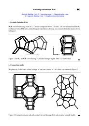
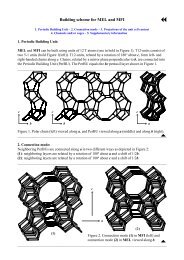
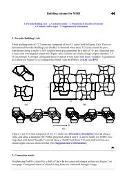
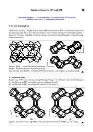
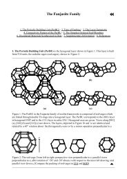
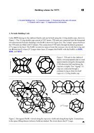
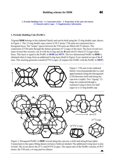
1. Periodic <strong>Building</strong> Unit (PerBU):<br />
Trigonal <strong>DDR</strong> belongs to the clathrasil family and can be built using the 12-ring double cups, shown<br />
in Figure 1. The 12-ring double cups consist of 30 T atoms. T30-units are connected into a<br />
hexagonal layer. The "empty" spaces between the T30-units are filled with T2-dimers. The<br />
connection of T30-units through the dimers generates [5 12 ]-cages in the layer. The layer reveals two<br />
types of nest-like recesses: site A with the 6-ring and site B (and site C) where [5 12 ]-cages share<br />
faces. This layer is equal to the PerBU in DOH and MTN. The two-dimensional PerBU in <strong>DDR</strong> is<br />
obtained when 6-rings from an additional 6-ring layer (bold in Figure 2) are stacked on top of the C<br />
sites. This stacking generates (small) [4 3 5 6 6 1 ]-cages. [Compare this PerBU with the PerBU in MEP]<br />
___________________________________________________________________________________<br />
Figure 1. T30-unit in the clathrasil<br />
c<br />
family viewed perpendicular to c and<br />
5<br />
approximately along the (hexagonal)<br />
[110] direction (left) and along the<br />
cup-axis c (right). Two "zigzag" 12-<br />
rings are connected though a<br />
common 6-ring to <strong>for</strong>m two half<br />
cages or a 12-ring double cup.<br />
__________________________________________________________________________________<br />
b<br />
5<br />
C<br />
4<br />
acos30<br />
B<br />
[5 12 ]-cage<br />
A<br />
4a<br />
[4 3 5 6 6 1 ]-cage<br />
Figure 2. Hexagonal PerBU in <strong>DDR</strong> viewed along the cup-axis c (left) and along b (top right).<br />
Connections to the space filling dimers (in heavy bold) are dashed. The additional 6-ring layer is also<br />
in bold. The in-set shows the [5 12 ]- and [4 3 5 6 6 1 ]-cages. The repeat unit of the PerBU consists of 40 T<br />
atoms: the T30-unit, a 6-ring and two dimers.<br />
___________________________________________________________________________________<br />
"
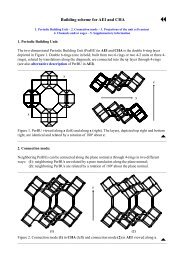
2. Connection mode:<br />
Neighboring PerBUs can be connected through O-bridges along +c in three different ways:<br />
(1) the second PerBU is shifted by +(2/3a + 1/3b) be<strong>for</strong>e connecting it to the first PerBU. The T30-<br />
units in the second PerBU are centered at (2/3, 1/3). This position is usually denoted as the B<br />
position as illustrated in Figure 2. The same connection mode can be repeated: a third PerBU is<br />
shifted with respect to the second layer by (again) +(2/3a + 1/3b). The T30-units are now centered at<br />
(4/3, 2/3) [or, equivalently, at (1/3, 2/3)]. This position is called the C position. Adding a fourth layer<br />
with the same connection mode gives a shift with respect to the first layer of (2a + b) [or zero, i.e.<br />
the A position]. The resulting stacking sequences, exhibiting the same connection mode, are denoted<br />
as AB, BC and CA, respectively, in analogy to stacking of dense packed spheres. The connection<br />
mode is illustrated in Figure 3(a).<br />
(2) the second and third PerBUs are shifted by -(2/3a + 1/3b) be<strong>for</strong>e connecting them along +c to<br />
the previous PerBU. The resulting stacking sequences AC, CB and BA, with the same connection<br />
mode are obtained. The connection mode is illustrated in Figure 3(b).<br />
(3) the second PerBU has a zero lateral shift along a and b. This connection mode leads to an AA,<br />
BB or CC stacking sequence depending on whether the added PerBU is connected to a PerBU with<br />
T30-units in the A, B or C position, respectively. The connection mode is illustrated in Figure 3(c).<br />
___________________________________________________________________________________<br />
[4 3 5 12 6 1 8 3 ]-cage<br />
c<br />
5<br />
C<br />
A<br />
B<br />
[4 3 566 1 ]-cages<br />
A<br />
B<br />
C<br />
(a)<br />
4 acos30<br />
Figure 3. (a): Connection mode (1) (AB, BC or CA connection mode) viewed approximately along<br />
[110] (left). In the perspective drawing only one set of A, B and C positions in each (shifted) PerBU<br />
is given in order to illustrate the new inter-layer cages <strong>for</strong>med. The projection along b (bottom right)<br />
shows the connection mode between complete PerBUs. (Parts of) the additional 6-rings are in bold.<br />
The inter-layer cages are shown at the top right. [Figure 3 is continued on next page]
fused [5 12 6 2 ] and<br />
[4 3 5 6 6 1 ]-cages<br />
A<br />
B<br />
C<br />
[4 3 5 9 7 3 ]-cage [5 15 6 1 7 3 ]-cage<br />
c<br />
5<br />
C<br />
A<br />
B<br />
(b)<br />
4 acos30<br />
[5 18 6 2 8 3 ]-cage<br />
c<br />
5<br />
C<br />
A<br />
B<br />
[4 6 5 6 8 3 ]-cage [4 3 5 6 6 1 ]-cages<br />
C<br />
A<br />
B<br />
(c)<br />
4 acos30<br />
Figure 3 [Cont’d]. (b): Mode (2) (AC, CB or BA connection mode) and (c): mode (3) (AA, BB or<br />
CC connection mode) viewed approximately along [110] (left). In these drawings only one set of A,<br />
B and C positions in each (shifted) PerBU is given in order to illustrate the new inter-layer cages<br />
<strong>for</strong>med. The projection along b (bottom right) shows the connection mode between complete<br />
PerBUs. (Parts of) the additional 6-rings are in bold. The inter-layer cages are shown at the top right.
"<br />
In <strong>DDR</strong> only connection mode (1) is observed.<br />
___________________________________________________________________________________<br />
3. Projections of the unit cell content: See Figure 4.<br />
___________________________________________________________________________________<br />
A<br />
b<br />
5<br />
C<br />
4 a<br />
c<br />
4<br />
Figure 4. Unit cell content in<br />
<strong>DDR</strong> viewed along [110] (left),<br />
B<br />
along b (middle) and along c<br />
(right). In the perspective drawing<br />
(left) each PerBU is represented<br />
by one T30-unit. (Parts<br />
c<br />
5<br />
of) the additional 6-rings are in<br />
bold. The stacking sequence is<br />
given in italics. The italic letters<br />
A<br />
give the position of the T30-unit<br />
relative to the A position in the<br />
4 acos30<br />
first PerBU.<br />
___________________________________________________________________________________<br />
4. Channels and/or cages:<br />
The [5 12 ]-cage and [4 3 5 6 6 1 ]-cage in the PerBU are shown in Figure 1. The two new types of interlayer<br />
cages in <strong>DDR</strong> are depicted in Figure 3(a). The pore descriptor is added. <strong>DDR</strong> can be<br />
considered as link between zeolites and clathrasils because it possesses zeolitic properties through a<br />
two-dimensional pore system along with 8-ring windows.<br />
___________________________________________________________________________________<br />
5. Supplementary in<strong>for</strong>mation:<br />
"<br />
Other framework types containing a layer of (modified) T30-units<br />
Three other framework types can be constructed using the (modified) PerBU described in Section 1.<br />
They belong to the clathrasil family.<br />
In the INTRO pages links are given to detailed descriptions of these framework types (choose:<br />
Clathrasils). There is also a link provided to a summary of the Periodic <strong>Building</strong> Units used in the<br />
building <strong>scheme</strong>s of these framework types (choose: Appendix; Figure 10).<br />
"<br />
"