Domestic RWH Systems - Kingspan Water
Domestic RWH Systems - Kingspan Water
Domestic RWH Systems - Kingspan Water

Create successful ePaper yourself
Turn your PDF publications into a flip-book with our unique Google optimized e-Paper software.
GL0132-02 (007018) – <strong>Domestic</strong> <strong>RWH</strong> Gravity Manual<br />
<strong>Domestic</strong> <strong>RWH</strong> <strong>Systems</strong><br />
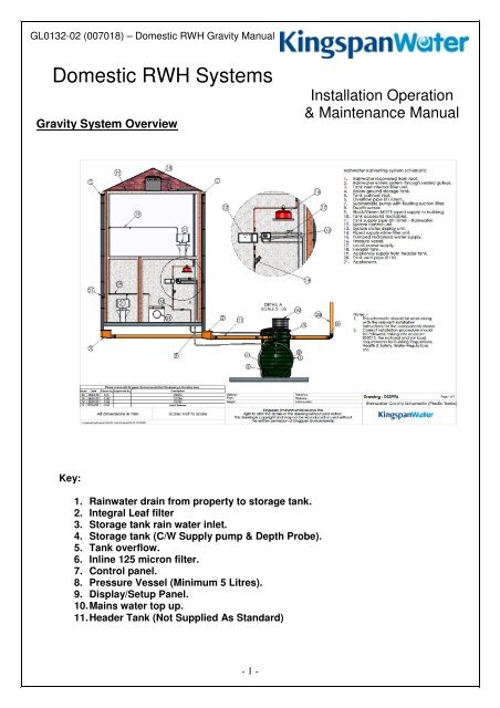
Gravity System Overview<br />
Installation Operation<br />
& Maintenance Manual<br />
Key:<br />
1. Rainwater drain from property to storage tank.<br />
2. Integral Leaf filter<br />
3. Storage tank rain water inlet.<br />
4. Storage tank (C/W Supply pump & Depth Probe).<br />
5. Tank overflow.<br />
6. Inline 125 micron filter.<br />
7. Control panel.<br />
8. Pressure Vessel (Minimum 5 Litres).<br />
9. Display/Setup Panel.<br />
10. Mains water top up.<br />
11. Header Tank (Not Supplied As Standard)<br />
- 1 -
GL0132-02 (007018) – <strong>Domestic</strong> <strong>RWH</strong> Gravity Manual<br />
Have You Considered<br />
Pressure Vessel<br />
These are a system requirement and it is essential these are<br />
sized to suit your specific application.<br />
Header Tank<br />
As you are installing a Gravity system a Header Tank is an<br />
essential part of the system.<br />
Please ensure this is sized to suit your particular application.<br />
Internal/External Pipe and Fittings<br />
Your delivery will NOT included any internal/external pipe and<br />
fittings that you will require to complete your installation.<br />
Please ensure all fittings are securely fitted to avoid any<br />
system issues.<br />
Tank & Control Kit Installation.<br />
Step 1 (Delivery):<br />
Firstly you must ensure you have received all components<br />
ordered.<br />
Please check your order against the delivery ticket which will<br />
list all delivered parts.<br />
Standard delivery will consist of a storage tank (size and style<br />
will vary from picture) and a boxed kit of parts.<br />
If there are any shortages or damaged components please<br />
contact us immediately.<br />
Step 2 (Excavation):<br />
Excavate a sufficient hole to suit storage tank (check sales<br />
drawings for dimensions). Ensure depth allows for a<br />
suitable concrete base (min 300mm). and there is sufficient<br />
room around tank for relevant backfill. If excavation walls<br />
are unstable use trench sheeting to shore up walls. A<br />
dewatering pump maybe required to remove excess water.<br />
- 2 -
GL0132-02 (007018) – <strong>Domestic</strong> <strong>RWH</strong> Gravity Manual<br />
Step 3 (Positioning):<br />
Lay the concrete base (min 300mm). Once cement is cured,<br />
lower the tank into the excavation, ensure you use correct<br />
lifting equipment, lift with webbing slings do not use chains.<br />
Ensure tank is level and all connections line up with site<br />
pipe work (if you are using an external filter you need to<br />
allow for these levels).<br />
Ensure access shafts are covered to avoid any debris falling<br />
into the tank during backfilling.<br />
Step 4 (Backfill):<br />
If necessary locate a dewatering pump in the base of the<br />
excavation to remove excess water (wet sites only).<br />
Fill the tank with water to approximately 300mm from base<br />
DO NOT OVERFILL. Backfill around tank with suitably<br />
selected material (concrete or pea shingle) DRY SITES<br />
ONLY, until level with the water line inside the tank. Fill<br />
tank and backfill in 300mm stages until you reach pipe<br />
connection levels.<br />
NB: Picture shows concrete backfill<br />
Step 5 (Pipe Connections):<br />
Connect rainwater drain to the inlet pipe on the storage tank<br />
Connect the overflow pipes to the relevant soak away/water<br />
course/sewer etc.<br />
Connect Ø25mm rainwater supply pipe to fitting in neck &<br />
run back to property.<br />
Connect mains top up supply pipe, this is clearly labelled on<br />
tank, and run pipe back to property.<br />
Run suitably sized electrical ducting, with draw wire, from<br />
neck to property.<br />
Step 6 (Pump/Probe Fitting):<br />
Assemble the pump fittings, Connect the hose to the pump<br />
outlet and secure with hose clips, connect opposite end to hose<br />
connector and secure with hose clip. Ensure rope is securely<br />
attached to pump.<br />
Lower the pump assembly into the tank shaft and locate upright<br />
on the base of the tank and connect to MDPE outlet in neck.<br />
Lower the depth probe into the tank and rest it on the base.<br />
Run pump & probe cable back to the property with draw wire.<br />
Finish by tying the pump rope to the U bolt in neck.<br />
- 3 -
GL0132-02 (007018) – <strong>Domestic</strong> <strong>RWH</strong> Gravity Manual<br />
Step 7 (Component Connections):<br />
Connect the rain water MDPE pipe to suitable internal pipe work<br />
via a stop cock then to the components in the following order:<br />
1. Inline leaf filter.<br />
2. Control panel plumbing box (fixed to wall).<br />
3. Suitably sized pressure vessel (supplied by others).<br />
4. Fix set up/display panel to the wall.<br />
Step 8 (Header Tank Connection):<br />
Run the pipe work form the pressure vessel to the header<br />
tank normally located in the roof space (NB please ensure<br />
your header tank is sized to suit your particular<br />
application).<br />
Run the mains pipe to the header tank and connect to the<br />
top pipe connection.<br />
Run pipe work form header tank and connect to relevant<br />
appliances in property.<br />
Step 9 (Finishing):<br />
Continue to backfill the tank up to ground level.<br />
When ground level is achieved trim the Ø600mm extension<br />
necks to suit.<br />
Fit man hole cover.<br />
NB: Pedestrian duty man hole cover supplied as standard,<br />
this is not suitable for traffic loading.<br />
Your Tank Installation Is Complete.<br />
Before continuing to Control & Display panel Connection check:<br />
1. System layout and install is as per the System Schematic Drawing supplied.<br />
2. Any debris, soil, dust etc that has accumulated during install is removed from the tank (to<br />
avoid blocking filter and supplying dirty water to system).<br />
3. Pump is standing upright and filter is also vertical.<br />
4. Pump, hose and fitting joints are sealed (if not suitably sealed it will cause system issues).<br />
5. Leaf Filter mesh is present in the housing.<br />
- 4 -
GL0132-02 (007018) – <strong>Domestic</strong> <strong>RWH</strong> Gravity Manual<br />
Control Panel & Display Panel Connection Detail.<br />
Step 1:<br />
The display panel should already be mounted in suitable<br />
location inside the property.<br />
Wire the display unit back to the control unit (up to 300m). This<br />
cable should be four cores at 1 amp per core rating (7/0.2 mm<br />
each core). The cable should be connected between the<br />
“REMOTE” terminal block on the DISPLAY unit to the remove<br />
terminal block on the CONTROL unit.<br />
Step 2:<br />
Locate the solenoid valve and install a local Switched Fused Spur<br />
(3 amp). Wire in the Solenoid Valve connector. Remove the screw<br />
on the back of the connector to release, then cable in to the spur<br />
using suitable 3 core cable. Feed the spur to the terminals in the<br />
controller marked DIRECT. Use the earth connection provided.<br />
Step 3:<br />
There are several sensors you can connect to the<br />
rainwater panel. Check the dip switches settings located<br />
in the middle of the printed circuit board to see what<br />
sensor is used in your system (standard is 4-20mA<br />
vented).<br />
Step 4:<br />
The sensor cable 2 cores should be connected in to the<br />
sensor terminal block (4-20Ma Level).<br />
The wires should be connected to the “+” and “-“ pins, . If<br />
there is a cable screen it should be connected to the “GND”<br />
pin.<br />
Step 5:<br />
The electrical supply should come from the Distribution Board,<br />
fused or with MCB Type C rated 16 amps, with a separate<br />
Residual Current Detector (RCD) to an isolate switch local to<br />
the control unit, or from a 16 amp switched fused spur with<br />
integral RCD. The mains supply terminal block is marked<br />
“POWER” connect accordingly to L brown core, N blue core<br />
and E green/yellow core.<br />
Your<br />
-<br />
Control<br />
5 -<br />
& Display Panels Are Now Connected.
GL0132-02 (007018) – <strong>Domestic</strong> <strong>RWH</strong> Gravity Manual<br />
Set Up & Commissioning.<br />
Step 1:<br />
Apply power to the system and observe the display unit.<br />
The system identifies that this is the first install and enters the<br />
setup wizard.<br />
Step 2:<br />
The wizard prompts the user to “Drop the sensor into the<br />
tank”, which should already have been done.<br />
Step 3:<br />
The system now asks is the tank full. If the tank is full enter Yes using<br />
the “UP”, “DOWN” and “ENTER/MENU” keys. This automatically saves<br />
the height of water in the tank.<br />
If the tank is not full enter No. In this case manually enter the height of<br />
the tank in centimetres. Press ENTER to continue (tank heights can be<br />
obtained from tank manufacturer documentation)<br />
Step 4:<br />
The controller now enters learning mode. The system will learn the<br />
maximum system operating pressure. The display will show an hour<br />
glass timer prompting the installer to wait until the system has fully<br />
pressurised. This will take a minimum of 4 minutes and, depending<br />
on the type of system, may take considerably longer.<br />
When max pressure has been learned the hour glass will disappear<br />
and the main screen will revert to normal mode.<br />
Step 5:<br />
To check that the system is pressurised go to “MAIN MENU”, go to<br />
“SETUP”, select “PRESSURE TEST” The pressure in indicated both by a<br />
readout expressing the system in PSI as well an arrow indicating the<br />
inclination of the pressure at that given moment. Ideally the system will<br />
show a steady pressure indicating that system has no leaks. If the<br />
system pressure is falling then there is an output open or there is a<br />
pressure leak.<br />
You have now completed set-up and commissioning. Test all appliances and check to ensure that the<br />
STATUS indicator light (ORANGE), which may have illuminated during set-up, has now extinguished. If<br />
the STATUS indicator light fails to extinguish within five minutes, switch off the system and go to the<br />
“Troubleshooting” section in Full manual.<br />
UK:<br />
Service Tel: +44 (0) 845 355 0555<br />
Service Fax: +44 (0) 1264 325245<br />
Ireland:<br />
Service Tel: +44 (0) 28 302 54077<br />
Service Fax: +44 (0) 28 302 60046<br />
- 6 -<br />
www.kingspanenv.com
GL0132-02 (007018) – <strong>Domestic</strong> <strong>RWH</strong> Gravity Manual<br />
<strong>Domestic</strong> <strong>Systems</strong> Wiring Diagram<br />
- 7 -