f - NASA Jet Propulsion Laboratory Technical Reports Server
f - NASA Jet Propulsion Laboratory Technical Reports Server
f - NASA Jet Propulsion Laboratory Technical Reports Server

You also want an ePaper? Increase the reach of your titles
YUMPU automatically turns print PDFs into web optimized ePapers that Google loves.
VIGILANTE - System Description and First Experiment Approach and Results<br />
Steven Suddarth', Michael Brewer', Suraphol Udomkesmalee', Carl Christian Liebe', Curtis Padgett',<br />
Hung Vo' and Larry Avril'<br />
'<strong>Jet</strong> <strong>Propulsion</strong> <strong>Laboratory</strong>, 4800 Oak Grove Dr, Pasadena CA 91 109-8099<br />
'Ballistic Missile Defense Organization, Washington, DC 20301<br />
ABSTRACT<br />
The VIGILANTE project is a planned vision system capable of tracking and recognizing targets in real time, on a small<br />
airborne platform. The project consists of two parts, 1) the Viewing ImagedGimballed Instrumentation <strong>Laboratory</strong><br />
(VIGIL), which is an infrared and visible sensor platform with appropriate optics and 2) the Analog Neural Three-<br />
dimensional processing Experiment (ANTE), a massive parallel, neural based, high-speed processor.<br />
The VIGIL sensors are mounted on a helicopter. VIGIL consists of an Optical Bench containing a visible camera, a Long<br />
Wave Infrared (LWIR) camera and a two axes gyro stabilized gimbaled mirror. The helicopter is also equipped with<br />
Global Position System (GPS) and an Inertial Measurement Unit (IMU) for attitude and position determination and two<br />
video links for ground based image collection. Finally, a jet powered, radio controlled VIGILANTE Target Vehicle<br />
(VTV) has been manufactured and equipped with GPS. In the first stages of the project, the VIGIL system is mounted in a<br />
Hughes 500 helicopter and is used to acquire image sequences of the VTV for training and testing of the ANTE image<br />
recognition processor. Based on GPS and IMU input, the gimbal is pointed toward the VTV and acquires images.<br />
This paper describes the VIGIL system in detail. It discusses the overall approach for the first flight experiment, the results<br />
of the experiment and the follow-on experiments that demonstrate real-time target recognition and tracking.<br />
Keywords: VIGILANTE, Airborne sensor, Attitude determining System, Field experiments.<br />
1. INTRODUCTION<br />
Small air and space borne systems capable of autonomous acquisition and identification of hostile targets (e.g., cruise<br />
missiles, missile launchers etc.) will become an essential component of the Ballistic Missile Defense Organization's<br />
(BMDO) planned defensive mechanisms. Such Automatic Target Recognition (ATR) capability could greatly increase the<br />
capabilities of interceptors (for cruise and ballistic missiles), surveillance platforms (for missile launchers), and ground-<br />
based fire control.<br />
The VIGILANTE project at <strong>Jet</strong> <strong>Propulsion</strong> <strong>Laboratory</strong> (JPL) [l] provides a low-cost airborne platform that combines new<br />
sensors with advanced neural network processing algorithms for detection, recognition and tracking of missile threats. The<br />
project consists of two parts, the airborne VIGIL platform and the ANTE ATR processor.<br />
VIGIL Wiewing Jmager/Qimballed Instrumentation <strong>Laboratory</strong>) is a helicopter-based gimballed camera platform<br />
providing data acquisition for target traininghecognition experiments as well as testing of novel active and passive focal<br />
plane sensors.<br />
' Further author information -<br />
s.s.: E-mail: steven.suddarth@,bmdo.osd.mil, M.B: E-mail: michael.p.brennerO,ipl.nasa.aov, S.U.: E-mail:<br />
suraphol.udomkesmaleeO,ipl.nasa.nov, C.C.L.:E-mail: carl.c.liebe@ipl.nasa.Pov, C.P.: E-mail:<br />
cpadPett@,pleides.ip,I.nasa.gov, H.V.: E-mail: hungvo@,rolans.jpl.nasa.gov, L.A.: E-mail: larrv.aVril@,iPl.nasa.aOV
The sensors are the Quantum Well Infrared Photodetector (QWIP), the Active Pixel Sensor (APS), and the Delta Dopped<br />
ultraviolet charged-coupled device (UV CCD). These three sensors cover the wavelength ranges 7.8 to 9, 0.4 to 1.0 and<br />
0.3 to 0.4 pm, respectively. VIGILANTE sensors can be queued to assist in the ATR functions of detection, classification,<br />
and precision tracking. For example, in a ballistic missile application, UV wavelengths (0.3 to 0.4 pm) could provide<br />
plume detection, IR (7.8 to 9pm) is suitable for cold body sensing / classification, and the visible wavelengths (0.4 to 1.0<br />
pm) can provide aim-point selection in the final approach / intercept. Eventually the VIGILANTE sensors may be used for<br />
simultaneous fusion of the data from multiple wavelengths. VIGIL provides realistic image conditions for airborne targets<br />
seen from above. To point the sensors toward the target (before the ANTE ATR becomes operational), both the helicopter<br />
and VTV are equipped with GPS receivers, to provide the pointing information<br />
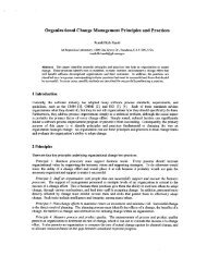
ANTE malog Neural Three-dimensional processing<br />
- Experiment) is a prototype image-processinghargetrecognition<br />
computer architecture based upon 3D circuit<br />
technology. The 3D circuit, known as the 3DANN-M can<br />
perform 64 simultaneous image convolutions with 64x64kernel<br />
size faster than video frame rates [2] - [6]. This<br />
technology can rapidly classify objects by both shape and<br />
spectral characteristics, and it provides a basic architecture<br />
I P6 Motherboard 1<br />
that can be easily miniaturized.<br />
described further in this paper.<br />
ANTE will not be<br />
VIGILANTE'S real-time target recognition will be<br />
demonstrated through a series of airborne experiments using<br />
real target images. The airborne experiments are critical for<br />
two major reasons: to acquire images under a wide variety<br />
of conditions to build the library set for algorithm<br />
development, and to integrate the system in the field under<br />
real conditions of flight operations. It is very important for<br />
algorithm development to acquire in flight imagery of<br />
targets rather than lab simulated.<br />
64 inner<br />
producrs<br />
Figure 1: The ANTE processing architecture that<br />
orchestrates the dataflow from sensor through neural<br />
processor also serves as the basis for developing<br />
methodologies for ATR applications. The 3DANN-M<br />
circuit is shown in the photo<br />
This paper describes VIGIL system in detail. It outlines the<br />
approach in bringing the system together and it outlines the<br />
results of the experiment. It also describes the plan for future experiments to demonstrate the complete system.<br />
2. DESCRIPTION OF THE VIGIL SYSTEM AND FLIGHT OPERATIONS<br />
VIGIL consists of an airborne helicopter equipped with the gimbal sensor platform, an attitude/telemetry system and a<br />
jet-powered target called the VTV. VIGIL sensor subsystems are shown in figure 2 and figure 3.
(a) (b)<br />
Figure 2. a) The VIGIL helicopter. b) Close up of the cargo bay in the helicopter with the camera platform.<br />
Helicopter<br />
n Ground Station<br />
Figure 3. Block diagram of the VIGIL sensor system.<br />
The VTV: is a re-useable, remote controlled target vehicle that supports testing of VIGILANTE, providing realistic<br />
scenarios to train and evaluate the ANTE system and its associated ATR algorithms. The VTV resembles a cruise missile,<br />
but is flown as a remote-controlled aircraft. An infrared signature is obtained from a Turbomin turbine engine producing 22<br />
pounds of thrust for a flight time of about 15 minutes with a signature of approximately 700 degrees C. The VTV is<br />
depicted in figure 4 a-c. It is 2.42 meters long, has a 1.18 meter wingspan and a mass of 25 kilograms. The VIGILANTE<br />
project team designed, assembled and flight tested the VTV with the help of professional model RC designers and pilots.<br />
The re-usable flight test vehicle is convenient for conducting low cost experiments, algorithm development, and image<br />
collection.<br />
(a) (b)<br />
Figure 4. - a) VTV fabrication. b) VTV Assembly. c) VTV completed.<br />
VIGILANTE Ultrasport 496: The Ultrasport 496 is a two-place helicopter built by Advanced Technologies Incorporated<br />
(ATI) in Newport News VA. VIGILANTE selected this platform to provide continuous, inexpensive airborne data<br />
collection. The aircraft was modified for the VIGIL sensors. The passenger seat was made flat to accommodate the<br />
optical bench and the vibration isolation system and a larger cavity was incorporated on the passenger side to house<br />
c<br />
VTV
electronic sub-assemblies like the gimbal electronics, telemetry electronics and the instrument batteries. The company<br />
fabricated, assembled and flight-tested it prior to integration. They also initiated the FAA registration as an experimental<br />
research and development vehicle and provided a trailer to transport the helicopter. The trailer also serves as a test station.<br />
The helicopter main structure is all composite construction and the helicopter engine is a 120 hp Hirth F-3014~ 2 cycle<br />
engine. The Ultrasport 496 is depicted in figure 5 a-c. Complete cost, Operation and maintenance of the aircraft is<br />
reasonable and one of the main reasons it was chosen as the VIGILANTE platform. A similar aircraft is also on its way to<br />
becoming an Unmanned Aria1 Vehicle (UAV) and our current telemetry system may provide a basis for future Unmanned<br />
operation. It should be noted that the size of the Ultrasport forced the design of the sub-assemblies to be small and low<br />
power. This design constraint may prove useful if current tests ultimately lead to operational airborne or space borne<br />
systems.<br />
(a) (b)<br />
Figure 5. a) Ultrasport Fabrication. b) System Integration. c) Flight Testing.<br />
The Ultrasport 496 is in test phase right now to determine its maximum flight envelope at National Test Pilot School<br />
(NTPS) in Mojave. The VIGILANTE instrumentation has temporarily been installed into a Hughes 500 in order to<br />
optimize schedules for Experiment #l. The Ultrasport 496 should be ready for the next series of experiments and it should<br />
greatly reduce operational costs.<br />
QUANTUM WELL INFRARED PHOTO DETECTOR (OWIP): is a 256x256-pixe1, real-time (30 to 120 Hz) IR sensor<br />
array mounted in an Inframetrics cooler and camera. QWIP is a low-cost, spatially uniform alternative to HgCdTe sensors.<br />
The sensor has an 8 to 9 pm central wavelength detection capability with a 1 pm full width at half maximum, and the<br />
design uses a random reflector on each pixel to maximize light trapping. The QWIP sensors are based on GaAs. The IR<br />
camera is equipped for a 200mm lens with a 2.5 degree field of view.<br />
VISIBLE CAMERA: A color Cohu CCD 768 x 494 pixel camera was used for experiment 1. The camera is mounted with<br />
a Fujinon 300-mm zoom lens. In near future, the CCD camera will be replaced with an active pixel sensor camera.<br />
ULTRAVIOLET CHARGED-COUPLED DEVICE (W CCD) CAMERA: The UV camera is a 1024x1024 pixel, real-time<br />
(30 - 120 Hz) Lumogen coated CCD. The W camera is equipped with 500 mm all reflective optics and various filters for<br />
specified UV and visible wavelengths. The camera has a two-channel digital RS-422 data output (half the sensor is read<br />
out per channel). The UV camera will be mounted on the Optical bench for the next VIGILANTE field experiment.<br />
VIBRATION ISOLATION SYSTEM: The Mechanical Engineering Departments of Catholic University and the University<br />
of Maryland has built an active/passive two stage vibration isolation system. The system operates on passive air mounts<br />
arranged in series with another stage of active electromagnetic actuators. The active stage isolates the base excitation from<br />
the intermediate platform whose vibration is isolated in turn from the primary system by the passive stage. The vibration<br />
isolation box is made of a composite material and contains the actuators, passive isolation, accelerometers and rate triad.<br />
The vibration box is controlled by a computer that logs the data and controls the I/O. The system can operated in two<br />
modes. Continuous operation mode isolates the optical bench with S/W controlled gain parameters, which have been<br />
optimized for a specific camera configuration. In data acquisition mode, the computer logs the output of the accelerometer<br />
and rate triads under various control gain conditions. Normally, this system reduces vibration-related acceleration by a<br />
factor of ten, and it was easily re-tuned during the transition form the Ultrasport 496 to the Hughes 500, where the
fundamental frequency changed from 16 Hz to about 11 Hz. After a series of flight tests under data logging conditions a<br />
frequency response was developed and suitable gain states and passive adjustment was implemented for the Visible and IR<br />
camera configuration. The vibration isolation system is depicted in Figure 6.<br />
Figure 6. Vibration Isolation System<br />
Active Actuators<br />
Jassive Isolation<br />
Composite Struct~ Ire<br />
TWO-AXIS GYRO-STABILIZED GIMBALED MIRROR: VIGIL'S Fraser-Volpe gimbal system consists of the gimbal<br />
electromechanical device itself and support electronics. The gimbal has an inner (horizontal) and outer (vertical) axis. The<br />
inner axis moves from -20 to +52 degrees and the outer axis moves +/- 45 degrees. The gimbal has two modes of<br />
operation: in position mode the mirror moves to the commanded position, in the rate mode the mirror slews at the<br />
command rate. In the rate mode, the gimbal also reduces vibration up to approximately 40Hz. The gimbal has RS 232<br />
control and interfaces to the telemetry system for command and data. The gimbal position is read out and transmitted to the<br />
ground station at 20 Hz.<br />
TELEMETRY SYSTEM: The VIGILANTE Telemetry system consists of three subsystems, as shown in figure 7:<br />
The Ground Station receives all the data from the helicopter and the VTV and provides a human interface to the<br />
system. It consists of several computers and rack-mounted communications equipment in the VIGIL trailer. All<br />
communication and navigation information is sent through a hub computer referred to as the Ground Control Unit<br />
(GCU). The GCU calculates the differential corrections and sends that information to the VTV and the helicopter. The<br />
ground station receives all the data from the aircraft and the VTV and sends it to VIGIL computer. The GCU has two<br />
57.6 Kbaud freewave modems and antennas, one for the VTV and the other for the aircraft command and data. Refer<br />
to Figure 7 below for specific hardware components.<br />
The helicopter telemetry system consists of two video down link channels,, command a communications router, an<br />
attitude GPS system, and an IMU. The video transmitters send images from the camera platform at 2.35-2.45 GHz<br />
down for ground-based recording and processing. The Communication Router (CR) distributes the commands from the<br />
ground to the airborne instrumentation and returns the GPS, Inertial Measurement Unit (IMU) and Gimbal data to the<br />
ground station. Finally, the Attitude GPS and the IMU provide aircraft position, attitude, velocities, accelerations and<br />
roll rates to the ground station. The CR is a Motorola-based processor that receives commands from the ground and<br />
sends the data back at 57.6 Kbaud. The CR contains a 900 MHz Freewave modem that sends and receives the data.<br />
The Attitude GPS system consists of a Pentium computer and 4 GPS receivers. The Attitude GPS system collects the<br />
GPS data from the 4 antennas, applies the received differential correction from the ground station and calculates a 4-
antenna attitude solution (note the GPS antennas on figure 2). It then transforms the attitude solution from the GPS<br />
antenna reference frame to the aircraft reference frame. The attitude system then sends the attitude (pitch, yaw and<br />
roll), position of the aircraft (north, east, and altitude), velocities (north, east and down) and the GPS time to the<br />
ground control station. The Inertial Measurement Unit (IMU) is located on the optical bench so it is vibration isolated.<br />
The IMU transmits the accelerations and the roll rates in three axes through the CR at 50Hz.<br />
Attitu e GPS Electronics<br />
f<br />
Communication Router Ground Conk01 Unit Inertial Measurement Unit<br />
Figure 7. Hardware Components for Telemetry System<br />
3. The VTV hardware consists of a GPS antenndreceiver and a freewave modem/antenna to receive the differential<br />
corrections and to send the position and velocity data to the ground station. The VTV calculates the latitude, longitude<br />
and altitude as well as the velocities east, north and down and transmits them to the ground station at 1OHz. The<br />
ground station calculates the relative VTV position with respect to the ground station.<br />
VIGILANTE POWER SYSTEM: The VIGILANTE Power System consists of the Pilot Control Electronics, Breaker Box<br />
and system batteries. The system batteries provide 24 volts to the sub-systems and will last approximately 1.5 hours under<br />
normal operation. The pilot control electronics provide the pilot independent power control, power on indication, voltage<br />
and current measurements of each sub-assembly. By utilizing power FET technology the voltage and currents supplied to<br />
the control electronics need only be minimal, which simplifies cable requirements, weight, and simplifies any hture<br />
requirements to remotely control system power distribution. The power system is relatively small and allows for easy<br />
integration into any air platform. The VIGILANTE Power System is depicted in Figure 8.<br />
(a)<br />
Figure 8. a) Pilot Control Electronics b) Breaker Box
FIELD SUPPORT EQUIPMENT: The VIGILANTE Ultrasport 496, VTV, Ground support racks and all the VIGILANTE<br />
sub-systems are transported to the test facility in the VIGILANTE trailer. The VIGILANTE trailer provides complete<br />
operation out on military ranges complete with AC generator to mobile phone. Hopefully mobile network link for data<br />
transfer and code updating capabilities will exist for the next experiment. The trailer is equipped currently with two<br />
ground support equipment racks that contain the VIGIL PC, Ground Control Unit and the video recorders and monitors.<br />
The ANTE PC will be added for the next experiment and it will contain the parallel processing system that will be<br />
performing real time target recognition. The mobility of the system is important for system integration testing as in GPS<br />
testing at the JPL parking lot to mobile operation in military installations due to the nature of the target vehicle. Support<br />
equipment depicted in Figure 9.<br />
(a)<br />
Figure 9. a) VIGILANTE Trailer. b) Ground Support Equipment.<br />
NATIONAL TEST PILOT SCHOOL: The National Test Pilot School and Flight research Inc. are commercial flight test<br />
and training operations that maintain and instrument experimental R&D aircraft, including both fixed and rotary wing.<br />
The staff at NTPS each have a minimum of 20 years experience as test pilots, flight test engineers, data analysts,<br />
mechanics etc. and are well versed in flight test plan writing, technical and safety review boards and formal reporting.<br />
NTPS has a joint use agreement with the US Air Force at Edwards AFB and the US Navy at China Lake to use restricted<br />
range areas, and can make these ranges available for VIGILANTE field tests with the VTV and helicopter. NTPS has at<br />
their disposal three runways, modem control tower, fire station and medivac making them a self contained flight operations<br />
center.<br />
3. VIGILANTE FIELD EXPERIMENTS OVERVIEW<br />
The VIGILANTE overall test objectives are;<br />
- DemonstrateNalidate next generation sensors (QWIP, APS and UV-CCD) technologies for BMDO applications<br />
- DemonstrateNalidate neural network processor technologies for BMDO applications.<br />
- Demonstrate a uniquely flexible, portable, low-cost test-bed for BMDO autonomous target recognition (ATR)<br />
technologies.<br />
- Collect test data for algorithm development and refinement.<br />
- Perform real-time detection, recognition and tracking of targets for BMDO applications.
Lab simulations: VIGILANTE integration and algorithm development began with lab simulation. System architecture,<br />
simulation speed and system performance and noise were analyzed, and image libraries were developed with hundreds of<br />
images of planes, missiles, helicopters, etc. over different scales and orientations and later used in simulations. The<br />
simulations yielded specifications and hnctionally tested hardware in the loop. Once the hardware is in place it is critical<br />
to get it out in the field under real target and background conditions. Experiments 0 and 1 have addressed this need.<br />
Experiment 0 checked out the sensor suite and attempted to collect imagery of operational cruise missiles at China Lake.<br />
This was critical for two reasons. Experiment 0 bridged the gap between laboratory simulated targets and real target and<br />
background data. Secondly it was important to get the sensors out in the field to develop an understanding on specific gain<br />
and offset values and calibration parameters. Experiment 0 was only partially successful, because the cruise missile target<br />
was self-destructed due to range-related issues. This is the VIGLANTE project has procured its own target vehicle (the<br />
VTV).<br />
Experiment 1 contains both the airborne platform and the VTV. As mentioned the airborne platform is the Hughes 500.<br />
This experiment demonstrated a GPS based tracking system and establish the ability to provide stable visible and IR<br />
images for ground based processing.<br />
Experiment 2 is scheduled for summer 1998. In this experiment, the ANTE PC containing the SHARC parallel processors<br />
will be used for target recognition and image based tracking. Experiment 3 and 4 are scheduled for 99 and will test the<br />
Neural Network and use the airborne platforms to simulate a mock-up intercept.<br />
4. SYSTEM INTEGRATION TESTING FOR EXPERIMENT 1<br />
The first test conducted with GPS based tracking system was performed at JPL in what is referred to as roof-top testing.<br />
The optical bench containing the gimbal and the visible camera were mounted on a roof that allowed for a down looking<br />
view of a temporary surrogate for the VTV (an RC helicopter equipped with the VTV electronics). The VTV was flown<br />
from a field about 500m from the sensor platform. At this point the interface specification between the GCU and the<br />
VIGIL PC was established. The data from the ATTGPS, IMU, GCU and VTV was incorporated in a S/W loop so that the<br />
VIGIL PC had the most recent data without asking for it. The VTV hovered, flew circular patterns, and figure-8's while<br />
the tracking algorithm tracked it via the gimbal. The algorithm used GPS data form the VTV and the attitude and the<br />
position of the optical bench. The attitude GPS antennas were mounted on a fixture to simulate the aircraft under similar<br />
baseline distances. Refer to the hardware configuration list below.<br />
HARDWARE CONFIGURATION OF ROOF-TOP TESTING:<br />
VTV Position data: Data at 10 Hz used for tracking<br />
IMU data: Not used, hardware not available yet.<br />
ATTGPS data (aircraft position and attitude): Data at 10 Hz used for tracking.<br />
Air platform:<br />
NIA<br />
Gimbal Position data: Data provided upon command.<br />
Main algorithm Tracking loop: Operating at 8 Hz.<br />
IMU/Attitude tracking solution: Not implemented yet.<br />
The next step was to integrate the system into the Ultrasport and to start a series of flight tests. The flight test were broken<br />
up into three phases, which are as follows:<br />
Phase 2: The helicopter in flight hovering approximate 10 feet off of the ground and the VTV static out in the range. This<br />
is to verify that the tracking algorithm is taking into account deviations in the aircraft's attitude and is pointing the gimbal<br />
accordingly.
Phase 3: This is the final phase using the RC helicopter and at the completion of this test the system should be ready for<br />
the real VTV traveling at speeds of 70 MPH. During this series of tests the aircraft and the VTV are both in the air. The<br />
VTV is performing a circular pattern out in the range and the aircraft is hovering at an altitude between 200-400 feet.<br />
Phase 1 started in November 1997 at NTPS, Mojave, CA. VIGIL was integrated into the Ultrasport. Testing proved the<br />
attitude-GPS to be too inconsistent and affected by multi-path or change of satellite constellations. During these tests the<br />
tracking algorithm utilized the VTV position data and the aircraft attitude and position data for tracking the RC helicopter.<br />
Preliminary tests of an IMU based tracking was performed, and an IMU algorithm as begun to eliminate the vagaries of the<br />
GPS-based attitude solution.<br />
HARDWARE CONFIGURATION OF PHASE 1 TESTING:<br />
VTV Position data: Data at 10 Hz used for tracking<br />
IMU data: Data at 1 OOHz used for preliminary tracking tests<br />
ATTGPS data (aircraft position and attitude): Data at 10 Hz used for tracking.<br />
Air platform:<br />
VIGILANTE Ultrasport 496<br />
Gimbal Position data: Data provided upon command.<br />
Main Algorithm Tracking loop: Operating at 3 Hz.<br />
IMU/Attitude tracking solution: Not implemented yet.<br />
Between November 97 and January 98 system upgrades were implemented to insure the system accuracy and stability. For<br />
example the upper GPS antennas on the aircraft were moved further away from the main rotor hub. Status bits were<br />
incorporated into all the GPS data to provide better visibility into the state of the hardware. The IMU was characterized<br />
over long periods of time to establish an understanding all the drift rates.<br />
Experiment 1 resumed at NTPS this February continuing on Phase 1 and proceeding to phases 2 and 3. During these tests<br />
the IMU data was integrated into the tracking loop and used with the attitude data of the aircraft. The air platform was<br />
temporarily changed from the Ultrasport 496 to a Hughes 500 pending flight envelope tests on the Ultrasport. The<br />
hardware configuration for the final phase 1-3 is listed below along with Figure 10 and 11 showing digitized images of<br />
tracking video for phase 2 and 3 respectively. Both phase 2 and 3 the VTV was approximately 830 m away and in phase 3<br />
the Hughes 500 was approximately hovering at 30 m.
Figure 10. Phase 1 - Selected images from a tracking video of the VTV. The images shown are very preliminary,<br />
and a radio-controlled helicopter on 1 m was used as VTV. The distance was approximately 830 m. The helicopter is<br />
the black spot in the center of the images. The field of view of the camera was approximately 3 degrees.<br />
HARDWARE CONFIGURATION OF PHASE 2 & 3 TESTING:<br />
VTV Position data: Data at 10 Hz used for tracking<br />
IMU data: Data at 50 Hz used for tracking tests<br />
ATTGPS data (aircraft position and attitude): Data at 10 Hz used for tracking.<br />
Air platform:<br />
Hughes 500.<br />
Gimbal Position data: Inner and Outer position provided at 20 Hz.<br />
Main Algorithm Tracking loop: Operating at 18 Hz.<br />
IMU/Attitude tracking solution: IMU and attitude tracking solution implemented.
Figure 11. Phase 3 - Selected images from a tracking video of the VTV. The images shown are very preliminary,<br />
and a radio-controlled helicopter on 1 m was used as VTV. The distance was approximately 830 m. The helicopter is<br />
the black spot in the center of the images. The field of view of the camera was approximately 3 degrees.<br />
6. SUMMARY<br />
VIGILANTE is a state-of -the-art processing / sensor system. This paper described VIGIL in detail and its subassemblies;<br />
two axis gyro stabilized gimbal mirror, Vibration Isolation system, LWIR and visible cameras and an attitude determining<br />
system. VIGIL will allow algorithm designers to have ready access to a complete airborne imagery system at very low<br />
cost and short turnaround times. VIGIL is a target tracking system based upon GPS information. The vibration isolation<br />
system, gimballed mirror and sensors have been integrated to provide very stable images for ground based processing and<br />
algorithm development.<br />
The VIGILANTE project has scheduled four experiments in the course of two years. Experiment 0 demonstrated a GPS<br />
based tracking system providing images of a surrogate cruise missile. The VIGILANTE system has been demonstrated as<br />
a flexible system that can be integrated into any aircraft. National Test Pilot School is a world class facility allowing for<br />
low cost operation and complete field test support. The VIGILANTE Target Vehicle will allow for the ease and flexibility<br />
for conducting multiple tests and image collection Possibilities. Experiment two is scheduled for the summer of 98 and<br />
will demonstrate the use of a parallel processing system for real-time target recognition and tracking. The last two<br />
experiments will contain the complete VIGIANTE system. This will include the ANTE processing system and on-board<br />
target recognition and tracking.
7. ACKNOWLEDGMENT<br />
The research described in this paper was carried out by the <strong>Jet</strong> <strong>Propulsion</strong> <strong>Laboratory</strong>, California Institute of Technology,<br />
and was sponsored by the Ballistic Missile Defense Organization through an agreement with the National Aeronautics and<br />
Space Administration.<br />
References herein to any specific commercial product, process, or service by tradename, trademark, manufacturer, or<br />
otherwise, does not constitute or imply its endorsement by the United States Government or the <strong>Jet</strong> <strong>Propulsion</strong> <strong>Laboratory</strong>,<br />
California Institute of Technology.<br />
8. REFERENCES<br />
S. Udomkesmalee et al: VIGILANTE: An Advanced SensingRrocessing Testbed for ATR Applications, SPIE Vol.<br />
3069, p. 82-93.<br />
Suraphol Udomkesmalee, Steven C. Suddarth: VIGILANTE: Ultrafast smart sensor for target recognition and<br />
precision tracking in a simulated CMD scenario. A IMMDO Technology Readiness Conference, San Diego, August<br />
18-22, 1997.<br />
Nelson Alhambra, Steven C. Suddarth, Suraphol Udomkesmalee: VIGILANTE Data Handling System: ASIM for<br />
Automatic Target Recognition. GOMAC’98 Micro-Systems and Their Applications, Arlington, Virginia, March 16-19,<br />
1998.<br />
A. Howard, C. Padgett, and C. C. Liebe: A multi-stage Neural Network for Automatic Target Detection, to appear in<br />
international Joint Conference on Neural Networks (IJCNN), May 1998.<br />
Curtis Padgett and Gail Woodward: A Hierarchical, Automated Target Recognition for a Parallel Analog Processor.<br />
The 1997 IEEE International Symposium on Computational Intelligence in Robotics and Automation, Monterey, July<br />
10-1 1, 1997.<br />
Curtis Padgett, M.Zhu, and S. Suddarth: Detection and orientation classifier for the VIGILANTE image processing<br />
system, SPIE international symposium on AerospaceDefense Sensing and Dual-use photonics.<br />
C.C. Liebe et all: VIGIL - A GPS Based Target Tracking System, SPIE Vol. xxxx, Orlando, April 1998.


![Ana]ysis of Reaction Products and Conversion Time in the Pyrolysis ...](https://img.yumpu.com/11715548/1/190x242/anaysis-of-reaction-products-and-conversion-time-in-the-pyrolysis-.jpg?quality=85)