f - NASA Jet Propulsion Laboratory Technical Reports Server
f - NASA Jet Propulsion Laboratory Technical Reports Server
f - NASA Jet Propulsion Laboratory Technical Reports Server

You also want an ePaper? Increase the reach of your titles
YUMPU automatically turns print PDFs into web optimized ePapers that Google loves.
fundamental frequency changed from 16 Hz to about 11 Hz. After a series of flight tests under data logging conditions a<br />
frequency response was developed and suitable gain states and passive adjustment was implemented for the Visible and IR<br />
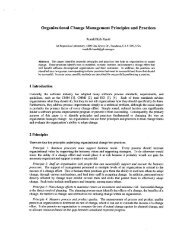
camera configuration. The vibration isolation system is depicted in Figure 6.<br />
Figure 6. Vibration Isolation System<br />
Active Actuators<br />
Jassive Isolation<br />
Composite Struct~ Ire<br />
TWO-AXIS GYRO-STABILIZED GIMBALED MIRROR: VIGIL'S Fraser-Volpe gimbal system consists of the gimbal<br />
electromechanical device itself and support electronics. The gimbal has an inner (horizontal) and outer (vertical) axis. The<br />
inner axis moves from -20 to +52 degrees and the outer axis moves +/- 45 degrees. The gimbal has two modes of<br />
operation: in position mode the mirror moves to the commanded position, in the rate mode the mirror slews at the<br />
command rate. In the rate mode, the gimbal also reduces vibration up to approximately 40Hz. The gimbal has RS 232<br />
control and interfaces to the telemetry system for command and data. The gimbal position is read out and transmitted to the<br />
ground station at 20 Hz.<br />
TELEMETRY SYSTEM: The VIGILANTE Telemetry system consists of three subsystems, as shown in figure 7:<br />
The Ground Station receives all the data from the helicopter and the VTV and provides a human interface to the<br />
system. It consists of several computers and rack-mounted communications equipment in the VIGIL trailer. All<br />
communication and navigation information is sent through a hub computer referred to as the Ground Control Unit<br />
(GCU). The GCU calculates the differential corrections and sends that information to the VTV and the helicopter. The<br />
ground station receives all the data from the aircraft and the VTV and sends it to VIGIL computer. The GCU has two<br />
57.6 Kbaud freewave modems and antennas, one for the VTV and the other for the aircraft command and data. Refer<br />
to Figure 7 below for specific hardware components.<br />
The helicopter telemetry system consists of two video down link channels,, command a communications router, an<br />
attitude GPS system, and an IMU. The video transmitters send images from the camera platform at 2.35-2.45 GHz<br />
down for ground-based recording and processing. The Communication Router (CR) distributes the commands from the<br />
ground to the airborne instrumentation and returns the GPS, Inertial Measurement Unit (IMU) and Gimbal data to the<br />
ground station. Finally, the Attitude GPS and the IMU provide aircraft position, attitude, velocities, accelerations and<br />
roll rates to the ground station. The CR is a Motorola-based processor that receives commands from the ground and<br />
sends the data back at 57.6 Kbaud. The CR contains a 900 MHz Freewave modem that sends and receives the data.<br />
The Attitude GPS system consists of a Pentium computer and 4 GPS receivers. The Attitude GPS system collects the<br />
GPS data from the 4 antennas, applies the received differential correction from the ground station and calculates a 4-


![Ana]ysis of Reaction Products and Conversion Time in the Pyrolysis ...](https://img.yumpu.com/11715548/1/190x242/anaysis-of-reaction-products-and-conversion-time-in-the-pyrolysis-.jpg?quality=85)