LAUREATE SERIES 2 DIGITAL PANEL METER ... - Laurel Electronics
LAUREATE SERIES 2 DIGITAL PANEL METER ... - Laurel Electronics
LAUREATE SERIES 2 DIGITAL PANEL METER ... - Laurel Electronics

Create successful ePaper yourself
Turn your PDF publications into a flip-book with our unique Google optimized e-Paper software.
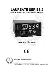
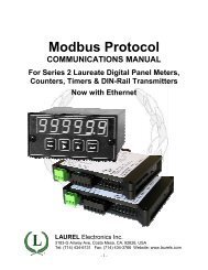
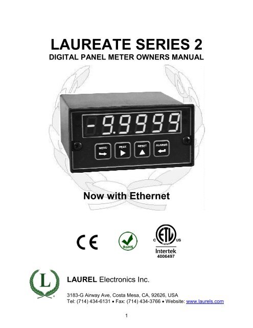
<strong>LAUREATE</strong> <strong>SERIES</strong> 2<br />
<strong>DIGITAL</strong> <strong>PANEL</strong> <strong>METER</strong> OWNERS MANUAL<br />
Now with Ethernet<br />
LAUREL <strong>Electronics</strong> Inc.<br />
3183-G Airway Ave, Costa Mesa, CA, 92626, USA<br />
Tel: (714) 434-6131 • Fax: (714) 434-3766 • Website: www.laurels.com<br />
1
1. ORDERING GUIDE<br />
Configure a model number in this format: L20201DCV1, CBL01<br />
L.Digital panel meter with<br />
screw terminal connectors.<br />
Display Color<br />
1 ............... DPM with green LED<br />
2 ...................DPM with red LED<br />
3 ..... Extended DPM, green LED<br />
4 ........ Extended DPM, red LED<br />
Note: Extended adds rate of<br />
change & linearization of nonlinear<br />
inputs. Not applicable to<br />
thermocouple or RTD inputs.<br />
Power<br />
0 ............................. 85-264 Vac<br />
1 .......... 10-48 Vdc or 12-32 Vac<br />
Setpoint Output<br />
0 ....................................... None<br />
1 ............. Two 8A contact relays<br />
2 .............. Two solid state relays<br />
3 ............ Four 8A contact relays<br />
4 ............. Four solid state relays<br />
Analog Output<br />
0 ....................................... None<br />
1 ...... 4-20 mA, 0-10V, -10/+10V<br />
Digital Interface<br />
0 ....................................... None<br />
1 ..................................... RS232<br />
2 ..................................... RS485<br />
4 ....................... RS485-Modbus<br />
5 ........................................ USB<br />
6 .........USB-to-RS485 converter<br />
7 .................................. Ethernet<br />
8 .. Ethernet-to-RS485 converter<br />
Input Type<br />
DC Volts<br />
DCV1 ...................... 200.00 mV<br />
DCV2 ......................... 2.0000 V<br />
DCV3 ......................... 20.000 V<br />
DCV4 ......................... 200.00 V<br />
DCV5* .......................... 600.0 V<br />
DCV6 ........................... 300.0 V<br />
DC Amperes<br />
DCA1 .................... 2.0000 mA<br />
DCA2 .................... 20.000 mA<br />
DCA3 .................... 200.00 mA<br />
DCA4 ......................... 5.000 A<br />
RTDs<br />
P385C ... Pt100, -202 to 850°C<br />
P385F .. Pt100, -331 to 1562°F<br />
P392C. .. Pt100, -202 to 850°C<br />
P392F .. Pt100, -331 to 1562°F<br />
N672C. .... Ni120, -80 to 260°C<br />
N672F .... Ni120, -112 to 500°F<br />
C427C. ... Cu10, -202 to 850°C<br />
C427F ... Cu10, -331 to 1562°F<br />
Thermocouples<br />
JC ..................... -210 to 760°C<br />
JF .................... -347 to 1400°F<br />
KC ................... -244 to 1372°C<br />
KF ................... -408 to 2501°F<br />
TC ..................... -257 to 400°C<br />
TF ..................... -430 to 752°F<br />
EC ................... -240 to 1000°C<br />
EF ................... -400 to 1830°F<br />
NC ................... -245 to 1300°C<br />
NF ................... -410 to 2370°F<br />
SC ..................... -46 to 1768°C<br />
SF ..................... -51 to 3214°F<br />
RC ..................... -45 to 1768°C<br />
RF ..................... -49 to 3213°F<br />
Resistance / Ohms<br />
R1 ................... 0-20.000 ohms<br />
R2 ................... 0-200.00 ohms<br />
R3 ................. 0-2.0000 kohms<br />
R4 ................. 0-20.000 kohms<br />
R5 ................. 0-200.00 kohms<br />
R6 .... 0-2 Mohms (fixed range)<br />
Process Signals<br />
(4-20 mA, 0-10V, etc.)<br />
P ............. 4-20 mA = 0-100.00<br />
P1.Custom Scaling<br />
Specify min signal & reading,<br />
max signal & reading.<br />
* Range not ETL approved.<br />
Strain Gauge, Potentiometer<br />
(4-wire ratio)<br />
SG ......... 0-200 mV = 0-100.00<br />
SG1 ................ Custom Scaling<br />
Specify min signal & reading,<br />
max signal & reading. Fullscale<br />
ranges 200 mV to 20V.<br />
RMS Volts<br />
RMV1 .................... 200.00 mV<br />
RMV2 ....................... 2.0000 V<br />
RMV3 ....................... 20.000 V<br />
RMV4 ....................... 200.00 V<br />
RMV5* ........................ 600.0 V<br />
RMV6 ......................... 300.0 V<br />
RMS Amperes<br />
RMA1 .................... 2.0000 mA<br />
RMA2 .................... 20.000 mA<br />
RMA3 .................... 200.00 mA<br />
RMA4 ......................... 5.000 A<br />
Load Cells (6-wire ratio)<br />
WM1...-99,999 to +99,999<br />
Specify min input signal & displayed<br />
reading, and max input<br />
signal & displayed reading.<br />
Full-scale inputs 20 mV to 500<br />
mV. 10 Vdc excitation.<br />
Options & Accessories<br />
BL ......... Blank lens, no button<br />
pads.<br />
CBL01 ... RJ11-to-DB9 RS232<br />
cable. Connects meter<br />
to PC com port.<br />
CBL02 ... USB-to-DB9 adapter.<br />
For use with CBL01.<br />
CBL05 ... USB-cable. Type A<br />
male to Type B male.<br />
IPC ........ NEMA-4 panel cover.<br />
BOX1 .... NEMA4 wall mount<br />
enclosure.<br />
BOX2 .... BOX1 plus IPC.<br />
2
2. TABLE OF CONTENTS<br />
1. ORDERING GUIDE ..................................................................................................... 2<br />
2. TABLE OF CONTENTS ............................................................................................... 3<br />
3. PRODUCT INTRODUCTION ....................................................................................... 4<br />
4. RECEIVING & UNPACKING ....................................................................................... 5<br />
5. SAFETY CONSIDERATIONS ...................................................................................... 5<br />
6. CONNECTOR WIRING INFORMATION ..................................................................... 6<br />
7. MECHANICAL ASSEMBLY ......................................................................................... 8<br />
8. FRONT <strong>PANEL</strong> SETUP KEYS .................................................................................... 10<br />
9. ENABLING & LOCKING OUT MENU ITEMS .............................................................. 12<br />
10. READING COORDINATES OF 2 POINTS SCALING METHOD ................................. 13<br />
11. DC VOLTS, AMPS, PROCESS, STRAIN INPUT ......................................................... 14<br />
12. LOAD CELL & MICROVOLT INPUT ............................................................................ 20<br />
13. AC RMS VOLTS & AMPS INPUT ................................................................................ 25<br />
14. THERMOCOUPLE INPUT ........................................................................................... 31<br />
15. RTD & RESISTANCE INPUT....................................................................................... 34<br />
16. DUAL & QUAD RELAY OUTPUT OPTIONS .............................................................. 39<br />
17. ANALOG OUTPUT OPTION ....................................................................................... 42<br />
18. SERIAL COMMUNICATION OPTIONS ....................................................................... 43<br />
19. EXCITATION OUTPUT & POWER SUPPLY ............................................................... 48<br />
20. INSTRUMENT SETUP VIA PC .................................................................................... 49<br />
21. CUSTOM CURVE LINEARIZATION ............................................................................ 52<br />
22. <strong>METER</strong> CALIBRATION ............................................................................................... 54<br />
23. SPECIFICATIONS ....................................................................................................... 55<br />
24. GLOSSARY OF TERMS .............................................................................................. 59<br />
25. WARRANTY ................................................................................................................ 64<br />
3
3. PRODUCT INTRODUCTION<br />
Our digital panel meters are versatile, cost effective solutions to a wide variety of monitoring<br />
and control applications. Depending on the choice of signal conditioner, they are easily set up<br />
for an accurate display of temperature, pressure, flow, weight, voltage or current, all in<br />
appropriate engineering units and with zero and span adjustment when needed. Setup can be<br />
via front panel pushbuttons or the meter’s serial interface. Selective security lockout of the<br />
front panel keys protects against accidental changes to meter setup.<br />
High read rates up to 60 per second (50 for 50 Hz operation) are made possible by<br />
Concurrent Slope Conversion (Pat 5,262,780), which integrates the signal over an AC power<br />
line cycle for maximum noise rejection. High read rates provide accurate peak and valley<br />
capture, and quick response for control applications. An adaptive digital filter supplies a time<br />
constant for the encountered signal noise level, yet responds rapidly to changes that exceed a<br />
selected threshold. Self-calibration occurs automatically after every 17th reading.<br />
The standard power supply is a high-efficiency switching unit that operates from AC or DC,<br />
and allows the meters to be powered from worldwide AC without changes. A low-voltage<br />
supply is optional for power from 10-48V batteries or from 12-30 Vac. Both supplies provide an<br />
isolated 5, 10 or 24Vdc transducer excitation output.<br />
The meter case conforms to the 1/8 DIN size standard. It is made of high impact, 94V-0 ULrated<br />
plastic and is watertight to NEMA-4 (IP65) when panel mounted. Mounting is from the<br />
front of the panel and requires less than 110 mm behind the panel. Power and signal wiring is<br />
via removable plugs conforming to UL61010C safety standards. All output options are isolated<br />
from meter and power ground to 250 Vac.<br />
Extended meter versions can linearize nonlinear inputs. Up to 180 data points may be<br />
linearized by a computer program that stores setup parameters in nonvolatile memory.<br />
Extended meters can also display rate of change, for example to display flow rate based on<br />
changing tank level.<br />
Alarm or setpoint control is provided by an optional relay board with two or four Form C 8A<br />
mechanical relays or two or four Form A 120 mA solid state relays. The setpoints may be<br />
latching or non-latching, be energized above or below the setpoint, or operate in a fail-safe<br />
mode. The relays can operate from the filtered signal to reduce relay chatter or from the<br />
unfiltered signal for fastest response. Snubber circuits and a programmable relay switching<br />
time delay extend relay contact life.<br />
An isolated analog output of 4-20 mA, 0-20 mA, 0-10V or -10 to +10V can be provided by an<br />
optional analog output board. The output is linearized to the display and can operate from the<br />
filtered or unfiltered signal input. It can be scaled via front panel pushbuttons or the meter’s<br />
serial interface.<br />
Ethernet USB, RS232, or RS485 (2-wire half-duplex or 4-wire full-duplex) serial communications<br />
options are available with the Modbus protocol or a simpler custom ASCII protocol.<br />
Modbus operation includes RTU or ASCII modes, up to 247 digital addresses, and up to 32<br />
devices per RS485 line without a repeater. Ethernet-to-RS485 and USB-to-RS485 converter<br />
boards allow a meter to be interfaced to a PC and to multiple meters on an RS485 network.<br />
Meter programming can be via the meter’s front panel or a PC running Windows based<br />
Instrument Setup Software (serial interface option required).<br />
4
4. RECEIVING & UNPACKING<br />
Your meter was carefully tested and inspected prior to shipment. Should the meter be<br />
damaged in shipment, notify the freight carrier immediately. In the event the meter is not<br />
configured as ordered or the unit is inoperable, return it to the place of purchase for repair or<br />
replacement. Please include a detailed description of the problem.<br />
5. SAFETY CONSIDERATIONS<br />
Warning: Use of this equipment in a manner other than specified may impair the protection<br />
of the device and subject the user to a hazard. Visually inspect the unit for signs of<br />
damage. If the unit is damaged, do not attempt to operate.<br />
Caution:<br />
• The unit must be connected to a Disconnect switch or a branch-circuit breaker, which must<br />
be in a suitable location<br />
• This unit must be powered by 85-264 Vac with the high voltage power supply option, or<br />
10-48 Vdc (12-32 Vac) with the low voltage power supply option. Verify that the proper<br />
power option is installed for the power to be used. This meter has no On/Off switch. It will<br />
be in operation as soon as power is connected.<br />
• The 85-264 Vac power connector (P1 Pins 1-3) is colored Green to differentiate it from<br />
other input and output connectors. The 12-32 Vac (10-48 Vdc) power connector is colored<br />
Black.<br />
• Do not make signal wiring changes or connections when power is applied to the instrument.<br />
Make signal connections before power is applied. If reconnection is required, disconnect<br />
power before such wiring is attempted.<br />
• To prevent electrical or fire hazard, do not expose the instrument to excessive moisture.<br />
• Do not operate the instrument in the presence of flammable gases or fumes; such an<br />
environment constitutes a definite safety hazard. This meter is designed to be mounted in a<br />
metal panel or a bench or wall mount style case. The spacing around the meter and the<br />
ventilation must be sufficient to maintain the ambient temperature at less than 55°C.<br />
• Verify the panel cutout dimensions, and mount according to instructions.<br />
Symbols used<br />
Caution (refer to accompanying documents)<br />
Caution, risk of electric shock.<br />
Equipment protected throughout by double<br />
insulation or reinforced insulation.<br />
Earth (ground) terminal.<br />
Both direct and alternating current.<br />
Operating environment:<br />
The meter is Class II (double insulated) equipment designed for use in Pollution degree 2.<br />
5
6. CONNECTOR WIRING INFORMATION<br />
CONNECTORS<br />
Connectors for signal and power are UL-rated<br />
screw-clamp terminal blocks that plug into<br />
mating jacks on the printed circuit board.<br />
Communication connectors are a single RJ11<br />
plug for RS232, dual RJ11 plugs for RS485,<br />
dual RJ45 plugs for RS485 Modbus, or USB.<br />
Note: Control inputs 1 & 2 of P1 are menu<br />
selectable.<br />
Warning: Hazardous voltages may be present<br />
on pins 4, 5 & 6 of P1 since digital ground is tied<br />
to pin 3 of P5 (-Signal Input). Keep pin 3 close to<br />
earth ground to minimize common mode voltage<br />
or shock hazard at pins 4, 5 & 6 of P1.<br />
6
P3 - SERIAL COMMUNICATIONS<br />
P4 - ANALOG OUTPUT<br />
RS232 INTERFACE<br />
Computer<br />
N/C<br />
ISO GND<br />
RX<br />
TX<br />
RTS<br />
N/C<br />
6<br />
5<br />
4<br />
3<br />
2<br />
1<br />
GND<br />
TX<br />
RX<br />
RTS<br />
RS485 INTERFACE - FULL DUPLEX<br />
RS485 INTERFACE - HALF DUPLEX<br />
ISO GND<br />
BRX<br />
ARX<br />
ATX<br />
BTX<br />
ISO GND<br />
6<br />
5<br />
4<br />
3<br />
2<br />
1<br />
GND<br />
BTX<br />
ATX<br />
ARX<br />
BRX<br />
GND<br />
ISO GND<br />
ATX / ARX<br />
BTX / BRX<br />
ISO GND<br />
6<br />
5<br />
4<br />
3<br />
2<br />
1<br />
GND<br />
ATX / ARX<br />
BTX / BRX<br />
GND<br />
RS485-MODBUS - FULL DUPLEX<br />
RS485-MODBUS - HALF DUPLEX<br />
(A') RXD0 -<br />
(B') RXD1 +<br />
(B) TXD1 *<br />
(A) TXD0 -<br />
ISO GND<br />
1<br />
2<br />
3<br />
4<br />
5<br />
6<br />
7<br />
8<br />
TXD0<br />
TXD1<br />
RXD1<br />
RXD0<br />
GND<br />
(B) TX / RXD1<br />
(A) TX / RXD0<br />
ISO GND<br />
1<br />
2<br />
3<br />
4<br />
5<br />
6<br />
7<br />
8<br />
(B) TX/RXD1<br />
(A) TX/RXD0<br />
GND<br />
7
7. MECHANICAL ASSEMBLY<br />
REMOVING THE REAR <strong>PANEL</strong><br />
First remove any connectors. Use one hand to press in the two sides of the rear of the<br />
case, and the other hand to press down the two protruding tab releases at the top of the<br />
rear panel (see figure below). This will unhook the rear panel from the case.<br />
Retaining tab<br />
with tab release<br />
Retaining tab<br />
with tab release<br />
Retaining tab<br />
Retaining tab<br />
REMOVING THE ELECTRONICS<br />
Rear Panel<br />
With the rear panel removed, grasp the power supply board to the left and signal conditioner<br />
board to the right, and carefully slide the electronic assembly out through the rear of<br />
the case. (see figure below).<br />
INSTALLING NEW 0PTION BOARDS<br />
Options boards plug into the main board at the front of the meter. These are plug-and-play<br />
and may be installed in the field. They will be recognized by the software, which will<br />
provide access to the menu items associated with that board. If necessary, remove rear<br />
panel knockouts for new boards. Boards plug into connectors as follows:<br />
Option Board Main Board Plug Rear Panel Jack<br />
Power supply<br />
Relay board<br />
Serial interface board<br />
Analog output board<br />
Signal conditioner board<br />
P11<br />
P12<br />
P13<br />
P14<br />
P15<br />
J1<br />
J2<br />
J3<br />
J4<br />
J5<br />
8
Note: Corresponding main board and option board connectors have the same number of<br />
electrical lines. When an option board is correctly installed, the top and bottom edges of the<br />
main board and option board are aligned.<br />
REASSEMBLING YOUR <strong>METER</strong><br />
Slide the electronics assembly into the case until the display board is seated flush against<br />
the front overlay. Insert the bottom tabs of the rear panel into the case, and then carefully<br />
align the board connectors with the openings in the rear panel. If necessary, remove any<br />
rear panel knockouts for new option boards that may have been installed. Ensure that all<br />
option boards are properly aligned with the molded board retaining pins on the inside of the<br />
rear panel. Once the rear panel is in place, reinstall the input/output screw clamp terminal<br />
plugs.<br />
<strong>PANEL</strong> MOUNTING<br />
Ensure that the panel mounted gasket is in place against the back of the bezel. Turn the two<br />
mounting screws counterclockwise until the space between the mounting pawl and the rear<br />
of the gasket is greater than the panel thickness. Insert the meter in the panel cutout. Turn<br />
the mounting screws clockwise until the meter is securely mounted in the panel. Do not<br />
overtighten.<br />
Dimensioned case drawings<br />
9
8. FRONT <strong>PANEL</strong> SETUP KEYS<br />
Meter Front Panel<br />
There are four front panel keys, which change function for the Run Mode and Menu Mode,<br />
effectively becoming eight keys. The keys are labeled with alphanumeric captions (MENU,<br />
PEAK, RESET, ALARMS) for the Run Mode and with symbols ( right arrow,<br />
right triangle, up triangle, left arrow) for the Menu Mode.<br />
FRONT <strong>PANEL</strong> LOCKOUT<br />
The Menu Mode will not work with most meters as received from the factory, since all menu<br />
items have been disabled in software and a lockout jumper is in place. That jumper needs to<br />
be removed for the Menu Mode to work, and menu items under Loc 1, Loc 2 and Loc 3 then<br />
need to be set to "0" via the front panel for these menu items to be unlocked See Section 9.<br />
The paragraphs below assume that all menu items have been unlocked.<br />
MENU MODE KEY ACTION<br />
In the Menu Mode, pressing a key momentarily advances to the next menu item. Holding<br />
down a key automatically advances through multiple menu items for fast menu navigation.<br />
KEYS IN RUN MODE<br />
MENU Key. Pressing MENU from the Run Mode enters the Menu Mode. Pressing<br />
MENU repeatedly will step the meter through the various menu items (if these have not<br />
been locked out) and then back to the Run Mode.<br />
PEAK Key. Pressing PEAK normally causes the peak value of the input signal to be<br />
displayed. The peak display then blinks to differentiate it from the normal present value<br />
display. Pressing PEAK again returns the display to the present value. The PEAK key<br />
can also be programmed to display Valley, alternating Peak or Valley, or to Tare the<br />
reading to zero. When Peak or Valley is selected, periodic horizontals bars at the top of<br />
the display indicate Peak, and periodic horizontals bars at the bottom indicate Valley.<br />
RESET Key. Pressing RESET with PEAK resets peak and valley values. Pressing<br />
RESET with ALARMS resets latched alarms. Pressing RESET with MENU performs a<br />
meter reset (same as power on). Meter reset can also be applied via a rear panel<br />
connect or a serial ASCII command.<br />
ALARMS Key. Pressing ALARMS once displays the setpoint for Alarm 1. Pressing it<br />
again displays the setpoint for Alarm 2. Pressing it again returns to the present value.<br />
10
KEYS IN MENU MODE<br />
Right Arrow Key (MENU). Pressing steps the meter through all menu items that<br />
have been enabled and then back to the Run Mode. With the DC signal conditioner<br />
board and no option boards, available menu items are _InPut, SEtuP, ConFG, _FiLtr,<br />
dEc.Pt, SCALE, OFFst, Loc 1, Loc 2, Loc 3. If a change has been made to a menu<br />
item, that change is saved to non-volatile memory when the key is pressed next,<br />
and StoreE is displayed briefly.<br />
Right Triangle Key (Digit Select).<br />
• Pressing from the InPut menu brings up all meter functions available with the<br />
meter's signal conditioner. For the DC signal conditioner, these are _dC U, _dC A<br />
and _rAtio.<br />
• Pressing from the SEtuP, ConfFG, FiLtr, SCALE, OFFSt, Loc 1, Loc 2 or Loc 3<br />
menus items sequentially selects digit positions 1 - 5, as indicated by a flashing digit:<br />
00000, 00000, 00000, 00000, 00000.<br />
• Pressing from the dEC.Pt menu item sequentially selects decimal point positions,<br />
which will flash: d.dddd dd.ddd ddd.dd dddd.d ddddd. .ddddd.<br />
Up Triangle Key (Value Select). Pressing for a flashing item (digit position or<br />
decimal point position) will increment that item. Pressing MENU will save any changes.<br />
Left Arrow Key (Reverse Menu). Pressing has the same effect as the MENU key,<br />
except that menu items are brought up in reverse order.<br />
11
9. ENABLING & LOCKING OUT MENU ITEMS<br />
For security reasons and ease of meter operation, any and all<br />
menu items may be disabled or "locked out" so that they are no<br />
longer directly accessible from the front panel. Each function to<br />
be disabled is set to "1" in menu items Loc 1, Loc 2 or Loc 3, and<br />
each function to be enabled is set to "0." The top menu items<br />
Loc 1, Loc 2 and Loc 3 can in turn be locked out by installing an<br />
internal hardware jumper. With the jumper installed, the operator<br />
only has access only to enabled menu items. With the jumper<br />
removed, the operator also has access to menu items Loc 1, Loc<br />
2 and Loc 3.<br />
SETTING HARDWARE LOCKOUT JUMPER<br />
To access the lockout jumper, remove the rear panel per Section<br />
9 and locate jumper “a” in the lower portion of the power supply<br />
board next to the input connectors (see figure at right).<br />
SETTING SOFTWARE LOCKOUTS<br />
When setting up the meter, it may be necessary to<br />
enable specific menu items by setting the corresponding<br />
lockout digit to 0. Be sure to reset the lockout<br />
digit to "1" if you do not want the menu item to be<br />
changed by an operator.<br />
Loc 1 Loc 2 Loc 3<br />
Press the MENU key until Loc 1, Loc 2 or Loc 3<br />
is displayed, as desired. Note: the hardware lockout<br />
jumper must be removed (see above).<br />
11111<br />
Press to display the lockout status, consisting of<br />
1’s and 0’s. The left digit will flash. Press again to<br />
step to the next digit, which will flash.<br />
00000<br />
12345<br />
Press to set the flashing digit to "0" to enable the<br />
menu item or to "1" to disable. Press MENU to enter.<br />
See the table to the right for list of menu items that<br />
can be enabled or disabled.<br />
Enabled or Disabled<br />
Menu Items<br />
Loc 1<br />
1 - Input type selection.<br />
2 - Meter setup, configuration<br />
& decimal pt.<br />
3 - Filter selection.<br />
4 - Scale or Lo, Hi input.<br />
5 - Offset or Lo, Hi reading<br />
Loc 2<br />
2 - Alarm setup.<br />
3 - Alarm setpoint value<br />
programming.<br />
4 - Analog output scaling.<br />
5 - Serial interface setup.<br />
Loc 3<br />
2 - View peak value<br />
3 - View alarm setpoints<br />
4 - Reset (peak & latched alarms)<br />
5 - Reset (meter reset)<br />
12
10. READING COORDINATES OF 2 POINTS SCALING METHOD<br />
When the reading coordinates of 2 points scaling method has been selected under SEtuP,<br />
the four menu items below will appear ahead of all other menu items when the MENU or<br />
key is first pressed from the run mode.<br />
This scaling method applies a straight line fit between two points, which are determined<br />
from actual transducer signals and the desired corresponding meter readings. A low signal,<br />
such as the output of a pressure transducer at zero pressure, and high signal, such as the<br />
output of the same transducer at a known high pressure, are applied to the meter. The<br />
desired corresponding low and high readings are then entered from the front panel. The<br />
meter then applies straight line fit between the high and low calibration points. This scaling<br />
method has the advantage of calibrating the transducer and meter as a system. The actual<br />
voltage or current at either point does not need to be known. This method is ideal for<br />
process and load cell meters, which require zero and span adjustment. It is also available<br />
for DC or AC meters. It is not available with thermocouple or RTD meters.<br />
The programming example below is for a process meter used with a 4-20 mA pressure<br />
transducer for 0 to 100 psi. Decimal points are set separately using the dEC.Pt menu.<br />
Press Menu Select<br />
Key<br />
Lo In Apply low signal input<br />
(e.g., transducer output for 0<br />
psi).<br />
Hi In Apply high signal input<br />
(e.g., transducer output for<br />
known 100.00 psi source).<br />
Lo rd<br />
Mode to enter desired low<br />
reading (e.g., 0.00).<br />
Hi rd<br />
Mode to enter desired high<br />
reading (e.g., 100.00).<br />
Press Digit Select<br />
Key<br />
_40.21 Press to display<br />
reading at low signal input<br />
(e.g., 4.021 mA).<br />
200.94 Press to display<br />
reading at high signal input<br />
(e.g., 20.094 mA).<br />
000.00 000.00 000.00<br />
000.00 000.00 Select digit<br />
to flash.<br />
000.00 000.00 000.00<br />
000.00 000.00 Select digit<br />
to flash.<br />
Press Value Select<br />
Key<br />
_40.21 Press<br />
reading.<br />
to store low<br />
200.94 Press to store high<br />
reading.<br />
100.00 Select -9 thru 9 for<br />
flashing first digit, 0 thru 9 for<br />
other flashing digits.<br />
100.00 Select -9 thru 9 for<br />
flashing first digit, 0 thru 9 for<br />
other flashing digits.<br />
13
11. DC VOLTS, AMPS, PROCESS, STRAIN INPUT<br />
The DC Volts, Amps, Process and Strain meters utilize the DC signal conditioner board, which<br />
needs to be configured via jumpers for the desired voltage or current range. All signal ranges<br />
are factory calibrated with calibration factors stored in EEPROM. The meter software<br />
recognizes the board and will bring up the appropriate menu items for it; however, it does not<br />
recognize the jumper settings. Please see further manual sections for setup of the following:<br />
relay output (16), analog output (17), communications (18), and excitation output (19).<br />
Board Revision N<br />
Voltage Ranges<br />
Jumpers<br />
FS Input E1 E2 E3<br />
±200.00 mV<br />
±2.0000 V<br />
±20.000 V<br />
±200.00 V<br />
±300V (UL)<br />
±600V (not UL)<br />
A<br />
A<br />
B<br />
B<br />
B<br />
B<br />
f<br />
f<br />
h<br />
h<br />
g<br />
g<br />
b<br />
a<br />
b<br />
a<br />
a<br />
a<br />
Current Ranges<br />
Jumpers<br />
FS Input E1 E2 E3<br />
±2.0000 mA<br />
±20.000 mA<br />
±200.00 mA<br />
±5.000 A<br />
A<br />
A<br />
A<br />
A<br />
e, g<br />
d, g<br />
c, g<br />
a, b, g<br />
b<br />
b<br />
b<br />
b<br />
Board Revision P (shipped between 15 Jan 2012 and 1 May 2012)<br />
Voltage Ranges Jumpers<br />
FS Input E1 E2<br />
±200.00 mV<br />
±2.0000 V<br />
±20.000 V<br />
±200.00 V<br />
±300V (UL)<br />
±600V (not UL)<br />
A<br />
B<br />
B<br />
B<br />
B<br />
B<br />
f<br />
k<br />
j<br />
h<br />
g<br />
g<br />
Current Ranges<br />
Jumpers<br />
FS Input E1 E2<br />
±2.0000 mA<br />
±20.000 mA<br />
±200.00 mA<br />
±5.000 A<br />
A<br />
A<br />
A<br />
A<br />
e, g<br />
d, g<br />
c, g<br />
a, b, g<br />
14
Board Revisions Q and R<br />
Voltage Ranges<br />
Jumpers<br />
FS Input E1 E2 E3<br />
±200.00 mV<br />
±2.0000 V<br />
±20.000 V<br />
±200.00 V<br />
±300V (UL)<br />
±600V (not UL)<br />
Current Ranges<br />
A<br />
A<br />
B<br />
B<br />
B<br />
B<br />
f<br />
f<br />
h<br />
h<br />
g<br />
g<br />
Jumpers<br />
b<br />
a<br />
b<br />
a<br />
a<br />
a<br />
FS Input E1 E2 E3<br />
±2.0000 mA<br />
±20.000 mA<br />
±200.00 mA<br />
±5.000 A<br />
A<br />
A<br />
A<br />
A<br />
e, g<br />
d, g<br />
c, g<br />
a, b, g<br />
b<br />
b<br />
b<br />
b<br />
E3<br />
b<br />
a<br />
E2<br />
E1<br />
h<br />
g<br />
f<br />
e<br />
B<br />
A<br />
a<br />
b<br />
c<br />
d<br />
1. Letters indicate jumper position. Jumpers are installed on pins adjacent to letters.<br />
2. Use 5 mm (0.2") jumpers for locations designated by a capital letter.<br />
3. Use 2.5 mm (0.1") jumpers for locations designated by a lower case letter.<br />
4. Store spare jumpers on an unused jumper post not associated a capital letter.<br />
SCALE & OFFSET SETUP<br />
For DC voltmeters & ammeters, a scale factor of 1 and an offset of 0 are used for direct<br />
readings in (milli)volts or (milli)amperes. Decimal point selection does not affect the displayed<br />
digits. For example, 0-20V or 0-20 mA signals can both be displayed as 0-20000. A full scale<br />
of 20000 may be displayed as 20.000 mA or 20000 µA. Use with a current shunt will require a<br />
scale factor to be set. For example, for a 500-100 (500A, 100 mV) shunt, divide 5000 (the<br />
desired full scale display with 0.1A resolution) by 10000 (displayed value with 100 mV when<br />
the scale factor is 1.0) for a scale factor of 0.5.<br />
For process & strain meters, scaling is normally set up from the front panel using the and<br />
keys, but can also be set up via RS232/485 using special PC-compatible setup software<br />
(available at no charge). The meter allows three scaling methods to be selected: 1) Scale and<br />
offset, 2) Coordinates of 2 points, and 3) Reading coordinates of 2 points. Only menu items<br />
applicable to the selected method will be presented.<br />
15
KEYSTROKES FOR SETUP<br />
If the MENU key does not work, see Section 9 “Enabling & Locking Out Menu Items.”<br />
Press Menu<br />
Select Key<br />
_InPut<br />
Selection of signal<br />
input type & range<br />
SEtuP<br />
Meter Setup<br />
_dC U<br />
DC Volts<br />
_dC A<br />
DC Amps<br />
Press Digit<br />
Select Key<br />
_rAtio<br />
Strain gauge & ratio<br />
00_00<br />
Display selection with<br />
scale factor of 1.<br />
00 _00<br />
Power line frequency<br />
00_ 00<br />
Scaling method<br />
00_00<br />
Control inputs 1 & 2:<br />
True = logic 1 (0V or<br />
tied to digital ground)<br />
False = logic 0 (5V or<br />
open)<br />
Press Value Select<br />
Key<br />
__0.2U __2.0U _20.0U 200.0U 600.0U<br />
0.2, 2, 20, 200, 660V FS<br />
__2.0a _20.0a _200.0a _5.0a<br />
0.2, 20, 200 mA, 5A FS<br />
__0.2U __2.0U _20.0U<br />
0.2, 2, 20V FS.<br />
0 4-1/2 digits (±20,000)<br />
1 Remote display (±99,999)<br />
2 4-1/2 digits, counts by 10 (±20,000)<br />
3 3-1/2 digits (±2,000)<br />
0 Noise minimized for 60 Hz<br />
1 Noise minimized for 50 Hz<br />
0 Scale and offset method<br />
1 Coordinates of 2 points method<br />
2 Reading coordinates of 2 points method<br />
0 1 = Reset, 2 = Meter Hold<br />
1 1 = Function Reset, 2 = Peak or Valley<br />
2 1 = Hold, 2 = Peak or Valley Display<br />
3 1 = Hold, 2 = Tare<br />
4 1 = Peak or Valley Display, 2 = Tare<br />
5 1 = Tare, 2 = Reset<br />
6 1 = 1, 2 = 1, decimal point = XXXXX<br />
1 = 0, 2 = 1, decimal point = XXXX.X<br />
1 = 1, 2 = 0, decimal point = XXX.XX<br />
1 = 0, 2 = 0, decimal point = XX.XXX<br />
7 1 = 1, 2 = 1, decimal point = XXXX.X<br />
1 = 0, 2 = 1, decimal point = XXX.XX<br />
1 = 1, 2 = 0, decimal point = XX.XXX<br />
1 = 0, 2 = 0, decimal point = X.XXXX<br />
8 1 = Function Reset, 2 = Display Blank<br />
9 1 = Hold, 2 = Display Blank<br />
A 1 = Peak or Valley, 2 = Display Blank<br />
B 1 = Tare, 2 = Display Blank<br />
C 1 = Valley Display, 2 = Peak Display<br />
D 1 = Tare, 2 = Reset Tare to Zero<br />
Both inputs 1 and 2 set to logic 1 for selections<br />
2, 4, A, C = Function Reset<br />
Both inputs 1 and 2 set to logic 1 for selections<br />
0, 1, 3, 5, 8, 9, B, D = Meter Reset<br />
16
Press Menu<br />
Select Key<br />
ConFG<br />
Meter Configuration<br />
FiLtr<br />
Filtering<br />
dEc.Pt<br />
Dec. point selection<br />
Press Digit<br />
Select Key<br />
000_0<br />
Operation as a rate of<br />
change meter.<br />
Extended meter only.<br />
000_0<br />
Operation of front<br />
panel PEAK button<br />
and rear connector for<br />
Peak or Valley Display<br />
000_0<br />
Auto-tare<br />
000_ 0<br />
Nonlinear input scaling<br />
Extended meter only.<br />
00000<br />
Alarm filtering<br />
00000<br />
Peak & Valley filtering<br />
00000<br />
Display filtering<br />
00000 Adaptive filter<br />
threshold<br />
00000<br />
Input signal filtering.<br />
Can be applied to display,<br />
setpoint, analog<br />
output, data output.<br />
d.dddd<br />
Decimal point flashes.<br />
Press Value Select<br />
Key<br />
0 Not rate of change<br />
1 Rate x 0.1 2 Rate x 1<br />
3 Rate x 10 4 Rate x 100<br />
5 Rate x 1000 6 Rate x 10000<br />
0 Peak Display. Also selects “Peak” in<br />
“Peak or Valley” at connector above.<br />
1 Valley Display. Also selects “Valley” in<br />
“Peak or Valley” at connector above.<br />
2 Peak (1st push), Valley (2nd push)<br />
3 Front panel Tare<br />
0 Meter comes up in normal run mode.<br />
1 Meter comes up in auto-tare mode<br />
0 Linear input<br />
1 Custom curve linearization<br />
0 Unfiltered output<br />
1 Filtered output<br />
0 Unfiltered Peak & Valley<br />
1 Filtered Peak & Valley<br />
0 Display batch average every 16 readings<br />
1 Display filtered signal<br />
0 Low adaptive filter threshold level<br />
1 High adaptive filter threshold level<br />
0 Autofilter<br />
1 Batch average, 16 readings<br />
2 Moving average, 0.08 sec.<br />
3 Moving average, 0.15 sec.<br />
4 Moving average, 0.3 sec.<br />
5 Moving average, 0.6 sec.<br />
6 Moving average, 1.2 sec.<br />
7 Moving average, 2.4 sec.<br />
8 Moving average, 4.8 sec.<br />
9 Moving average, 9.6 sec.<br />
A Unfiltered<br />
d.dddd dd.ddd ddd.dd dddd.d ddddd.<br />
.ddddd Press to shift the decimal point.<br />
17
Press Menu<br />
Select Key<br />
Press Digit<br />
Select Key<br />
Press Value Select<br />
Key<br />
Scaling method “Scale and Offset” if selected under SEtuP<br />
SCALE<br />
Scale factor<br />
OFFst<br />
Offset value<br />
0.0000 0.0000 0.0000<br />
0.0000 0.0000 0.0000<br />
Select digit to flash.<br />
0.0000 0.0000 0.0000<br />
0.0000 0.0000<br />
Select digit to flash.<br />
Scaling method “Coordinates of 2 points” if selected under SEtuP<br />
Lo In.<br />
Low signal input.<br />
Lo rd<br />
Desired reading at<br />
Lo In.<br />
Hi In.<br />
High signal input.<br />
Hi rd.<br />
Desired reading at<br />
Hi In.<br />
0.0000 0.0000 0.0000<br />
0.0000 0.0000<br />
Select digit to flash.<br />
0.0000 0.0000 0.0000<br />
0.0000 0.0000<br />
Select digit to flash.<br />
0.0000 0.0000 0.0000<br />
0.0000 0.0000<br />
Select digit to flash.<br />
0.0000 0.0000 0.0000<br />
0.0000 0.0000<br />
Select digit to flash.<br />
Select -9 thru 9 for flashing first digit, 0 thru 9<br />
for other flashing digits. Select decimal point<br />
location when decimal point is flashing.<br />
Select -9 thru 9 for flashing first digit, 0 thru 9<br />
for other flashing digits. Decimal point<br />
location is selected by dEC.Pt.<br />
Select -9 thru 9 for flashing first digit, 0 thru 9<br />
for other flashing digits. Decimal point is set<br />
by input range chosen.<br />
Select -9 thru 9 for flashing first digit, 0 thru 9<br />
for other flashing digits. Decimal point is set<br />
by dEC.Pt.<br />
Select -9 thru 9 for flashing first digit, 0 thru 9<br />
for other flashing digits. Decimal point is set<br />
by input range chosen.<br />
Select -9 thru 9 for flashing first digit, 0 thru 9<br />
for other flashing digits. Decimal point is set<br />
by dEC.Pt.<br />
Scaling method “Reading coordinates of 2 points” if selected under SEtuP<br />
Lo In.<br />
Low signal input.<br />
Hi In.<br />
High signal input.<br />
Lo rd<br />
Desired reading at<br />
Lo In.<br />
Hi rd.<br />
Desired reading at<br />
Hi In.<br />
_0.021<br />
Apply a low reference<br />
signal to the meter.<br />
_20.094<br />
Apply a high reference<br />
signal to the meter.<br />
0.0000 0.0000 0.0000<br />
0.0000 0.0000<br />
Select digit to flash.<br />
0.0000 0.0000 0.0000<br />
0.0000 0.0000<br />
Select digit to flash.<br />
_0.021<br />
Press<br />
meter.<br />
_0.021<br />
Press<br />
meter.<br />
to store the low signal input in the<br />
to store the high signal input in the<br />
0.0000<br />
Select -9 thru 9 for flashing first digit, 0 thru 9<br />
for other flashing digits. Decimal point is set<br />
by dEC.Pt.<br />
6.7500<br />
Select -9 thru 9 for flashing first digit, 0 thru 9<br />
for other flashing digits. Decimal point is set<br />
by dEC.Pt.<br />
18
Option board dependent menu items<br />
ALSEt. ALS34 dEU1H dEU2H dEU1b dEU2b dEU3H DEU4H DEU3b DEU4b<br />
Menu items related to alarm setup These will only appear if a relay board is detected. If so,<br />
please see Section16.<br />
AnSEt. An Lo. An Hi..<br />
Menu items related to analog output setup. These will only appear if an analog output<br />
board is detected. If so, see Section 17.<br />
SEr 1. SEr 2. SEr 3. SEr 4. _Addr<br />
Menu items related to serial communications. These will only appear if an RS232, RS485<br />
or USB I/O board is detected. If so, see Section 18.<br />
Menu lockout items<br />
Loc 1. Loc 2. Loc 3.<br />
Menu items used to enable or lock out (hide) other menu items. Loc menu items may in turn<br />
be locked out by a hardware jumper. Please see Section 9.<br />
* Scaling method 2, “Reading Coordinates of 2 Points Scaling Method,” will appear before all<br />
other Menu items, including _InPut. Decimal point is set by dEC.Pt.<br />
19
12. LOAD CELL & MICROVOLT INPUT<br />
The Load Cell and Microvolt meters utilize the load cell signal conditioner board, which offers<br />
sensitivity to ±20 mV full scale and 4 or 6-wire load cell connection. This board needs to be<br />
configured via jumpers for the desired voltage range. All signal ranges are factory calibrated<br />
with calibration factors stored in EEPROM. The meter software recognizes the board and will<br />
bring up the appropriate menu items for it; however, it does not recognize the jumper settings.<br />
Please see further manual sections for setup of the following features: relay output (16),<br />
analog output (17), communications (18), and transducer excitation output (19).<br />
RANGE SELECTION VIA JUMPERS<br />
Ranges & Display with<br />
Scale Factor = 1<br />
Input<br />
±20 mV<br />
±50 mV<br />
±100 mV<br />
±250 mV<br />
±500 mV<br />
Jumpers<br />
e<br />
a<br />
b<br />
c<br />
d<br />
Full scale<br />
display<br />
±20000<br />
±50000<br />
±10000<br />
±25000<br />
±50000<br />
Notes<br />
1. See Section 19 to select 10V excitation.<br />
2. Jumpers are 2.5 mm (0.1 in).<br />
SCALE & OFFSET SETUP<br />
For DC microvolt meters, a scale factor of 1 and an offset of 0 are used for direct readings in<br />
microvolts or millivolts. Decimal point selection does not affect the displayed digits. For<br />
example, 20 mV can be displayed as 20.000 mV or 20000 µV. The decimal point is set<br />
separately.<br />
For load cell applications, scaling is normally set up from the front panel using the and<br />
keys, but can also be set up via RS232/485 using special PC-compatible setup software<br />
(available at no charge). The meter allows three scaling methods to be selected: 1). Manual<br />
scale and offset, 2) Coordinates of 2 points, and 3) Reading coordinates of 2 points. Please<br />
see the Glossary for an explanation of each method.<br />
20
KEYSTROKES FOR SETUP<br />
If the MENU key does not work, see Section 9 “Enabling & Locking Out Menu Items.”<br />
Press Menu<br />
Select Key<br />
_InPut<br />
Selection of signal<br />
input type & range<br />
SEtuP<br />
Meter Setup<br />
Press Digit<br />
Select Key<br />
_Strn<br />
Strain or ratiometric<br />
_dC u U<br />
DC millivolts<br />
00_00<br />
Display type<br />
00 _00<br />
Power line frequency<br />
00_ 00<br />
Scaling method<br />
00_00<br />
Rear connector control<br />
inputs 1 & 2.<br />
True = logic 1 (0V or<br />
tied to digital ground)<br />
False = logic 0 (5V or<br />
open)<br />
Press Value Select<br />
Key<br />
_20.0____50.0_ _100.0 _250.0 _500.0<br />
20, 50, 100, 250, 500 mV FS voltage<br />
_20.0____50.0_ _100.0 _250.0 _500.0<br />
20, 50, 100, 250, 500 mV FS voltage<br />
0 4-1/2 digit meter, counts by 1<br />
1 5-digit remote display (±99,999)<br />
2 4-1/2 digit meter, counts by 10<br />
3 3-1/2 digit meter<br />
0 Noise minimized for 60 Hz<br />
1 Noise minimized for 50 Hz<br />
0 Scale and offset method<br />
1 Coordinates of 2 points method<br />
2 Reading coordinates of 2 points method<br />
0 1 = Reset, 2 = Meter Hold<br />
1 1 = Function Reset 2 = Pk or Valley Disp.<br />
2 1 = Meter Hold 2 = Pk or Valley Disp.<br />
3 1 = Meter Hold 2 = Tare<br />
4 1 = Peak or Valley 2 = Tare<br />
5 1 = Tare 2 = Reset<br />
6 1 = 0, 2 = 0, decimal point 1= XXXXX<br />
1 = 1, 2 = 0, decimal point 1 = XXXX.X<br />
1 = 0, 2 = 1, decimal point 1 = XXX.XX<br />
1 = 1, 2 = 1, decimal point 1 = XX.XXX<br />
7 1 = 0, 2 = 0, decimal point 2 = XXXX.X<br />
1 = 1, 2 = 0, decimal point 2 = XXX.XX<br />
1 = 0, 2 = 1, decimal point 2 = XX.XXX<br />
1 = 1, 2 = 1, decimal point 2 = X.XXXX<br />
8 1 = Function Reset 2 = Display Blank<br />
9 1 = Hold 2 = Display Blank<br />
A 1 = Peak or Valley 2 = Display Blank<br />
B 1 = Tare<br />
2 = Display Blank<br />
C 1 = Valley Display 2 = Peak Display<br />
D 1 = Tare<br />
2 = Tare Reset<br />
Both control inputs 1 & 2 set to 1 for selections<br />
2, 4, A, C = Function Reset.<br />
Both control inputs 1 & 2 set to 1 for selections<br />
0, 1, 3, 5, 8, 9, B, D = Meter Reset.<br />
21
Press Menu<br />
Select Key<br />
ConFG<br />
Meter Configuration<br />
FiLtr<br />
Filtering<br />
dEc.Pt<br />
Dec. point selection<br />
Press Digit<br />
Select Key<br />
000_0<br />
Operation as a rate of<br />
change meter.<br />
Extended meter only.<br />
000_0<br />
Operation of front<br />
panel PEAK button<br />
and rear connector for<br />
Peak or Valley Display<br />
000_0<br />
Auto-tare<br />
000_ 0<br />
Nonlinear input scaling<br />
Extended meter only.<br />
00000<br />
Alarm filtering<br />
00000<br />
Peak & Valley filtering<br />
00000<br />
Display filtering<br />
00000 Adaptive filter<br />
threshold<br />
00000<br />
Input signal filtering.<br />
Can be applied to display,<br />
setpoint, analog<br />
output, data output.<br />
d.dddd<br />
Decimal point flashes.<br />
Press Value Select<br />
Key<br />
0 Not rate of change<br />
1 Rate x 0.1<br />
2 Rate x 1<br />
3 Rate x 10<br />
4 Rate x 100<br />
5 Rate x 1000<br />
6 Rate x 10000<br />
0 Peak Display. Also selects “Peak” in<br />
“Peak or Valley” at connector above.<br />
1 Valley Display. Also selects “Valley” in<br />
“Peak or Valley” at connector above.<br />
2 Peak (1st push), Valley (2nd push)<br />
3 Front panel Tare<br />
0 Meter comes up in normal run mode.<br />
1 Meter comes up in auto-tare mode<br />
0 Linear input<br />
1 Custom curve linearization<br />
0 Unfiltered output<br />
1 Filtered output<br />
0 Unfiltered Peak & Valley<br />
1 Filtered Peak & Valley<br />
0 Display batch average every 16 readings<br />
1 Display filtered signal<br />
0 Low adaptive filter threshold level*<br />
1 High adaptive filter threshold level<br />
0 Autofilter<br />
1 Batch average, 16 readings<br />
2 Moving average, 0.08 sec.<br />
3 Moving average, 0.15 sec.<br />
4 Moving average, 0.3 sec.<br />
5 Moving average, 0.6 sec.<br />
6 Moving average, 1.2 sec.<br />
7 Moving average, 2.4 sec.<br />
8 Moving average, 4.8 sec.<br />
9 Moving average, 9.6 sec.<br />
A Unfiltered<br />
d.dddd dd.ddd ddd.dd dddd.d ddddd.<br />
.ddddd<br />
22
Press Menu<br />
Select Key<br />
Press Digit<br />
Select Key<br />
Press Value Select<br />
Key<br />
Scaling method “Scale and Offset” if selected under SEtuP<br />
SCALE<br />
Scale factor<br />
OFFst<br />
Offset value<br />
0.0000 0.0000 0.0000<br />
0.0000 0.0000 0.0000<br />
Select digit to flash.<br />
0.0000 0.0000 0.0000<br />
0.0000 0.0000<br />
Select digit to flash.<br />
Scaling method “Coordinates of 2 points” if selected under SEtuP<br />
Lo In.<br />
Low signal input.<br />
Lo rd<br />
Desired reading at<br />
Lo In.<br />
Hi In.<br />
High signal input.<br />
Hi rd.<br />
Desired reading at<br />
Hi In.<br />
0.0000 0.0000 0.0000<br />
0.0000 0.0000<br />
Select digit to flash.<br />
0.0000 0.0000 0.0000<br />
0.0000 0.0000<br />
Select digit to flash.<br />
0.0000 0.0000 0.0000<br />
0.0000 0.0000<br />
Select digit to flash.<br />
0.0000 0.0000 0.0000<br />
0.0000 0.0000<br />
Select digit to flash.<br />
Select -9 thru 9 for flashing first digit, 0 thru 9<br />
for other flashing digits. Select decimal point<br />
location when decimal point is flashing.<br />
Select -9 thru 9 for flashing first digit, 0 thru 9<br />
for other flashing digits. Decimal point<br />
location is selected by dEC.Pt.<br />
Select -9 thru 9 for flashing first digit, 0 thru 9<br />
for other flashing digits. Decimal point is set<br />
by input range chosen.<br />
Select -9 thru 9 for flashing first digit, 0 thru 9<br />
for other flashing digits. Decimal point is set<br />
by dEC.Pt.<br />
Select -9 thru 9 for flashing first digit, 0 thru 9<br />
for other flashing digits. Decimal point is set<br />
by input range chosen.<br />
Select -9 thru 9 for flashing first digit, 0 thru 9<br />
for other flashing digits. Decimal point is set<br />
by dEC.Pt.<br />
Scaling method “Reading coordinates of 2 points” if selected under SEtuP<br />
Lo In.<br />
Low signal input.<br />
Hi In.<br />
High signal input.<br />
Lo rd<br />
Desired reading at<br />
Lo In.<br />
Hi rd.<br />
Desired reading at<br />
Hi In.<br />
_0.021<br />
Apply a low reference<br />
signal to the meter.<br />
_20.094<br />
Apply a high reference<br />
signal to the meter.<br />
0.0000 0.0000 0.0000<br />
0.0000 0.0000<br />
Select digit to flash.<br />
0.0000 0.0000 0.0000<br />
0.0000 0.0000<br />
Select digit to flash.<br />
_0.021<br />
Press<br />
meter.<br />
to store the low signal input in the<br />
_20.094<br />
Press to store the high signal input in the<br />
meter.<br />
0.0000<br />
Select -9 thru 9 for flashing first digit, 0 thru 9<br />
for other flashing digits. Decimal point is set<br />
by dEC.Pt.<br />
6.7500<br />
Select -9 thru 9 for flashing first digit, 0 thru 9<br />
for other flashing digits. Decimal point is set<br />
by dEC.Pt.<br />
23
Option board dependent menu items<br />
ALSEt. ALS34 dEU1H dEU2H dEU1b dEU2b dEU3H DEU4H DEU3b DEU4b<br />
Menu items related to alarm setup These will only appear if a relay board is detected. If so,<br />
please see Section16.<br />
AnSEt. An Lo. An Hi..<br />
Menu items related to analog output setup. These will only appear if an analog output<br />
board is detected. If so, see Section 17.<br />
SEr 1. SEr 2. SEr 3. SEr 4. _Addr<br />
Menu items related to serial communications. These will only appear if an RS232, RS485<br />
or USB I/O board is detected. If so, see Section 18.<br />
Menu lockout items<br />
Loc 1. Loc 2. Loc 3.<br />
Menu items used to enable or lock out (hide) other menu items. Loc menu items may in turn<br />
be locked out by a hardware jumper. Please see Section 9.<br />
24
13. AC TRUE RMS VOLTS & AMPS INPUT<br />
AC voltage or current measurement utilizes the True<br />
RMS signal conditioner board which uses precision<br />
circuitry to compute the root-mean-square of complex<br />
waveforms from 10 Hz to 10 kHz. Accurate measurements<br />
are obtained with spikes up to 3 times the<br />
maximum of each range. The input can be AC<br />
coupled to read only the AC component, such as<br />
ripple on a power supply, or DC coupled to read AC<br />
plus DC. The board needs to be configured via<br />
jumpers for the desired voltage or current range, and<br />
for AC or DC coupling. All signal ranges are factory<br />
calibrated with calibration factors stored in EEPROM.<br />
The meter software recognizes the board and will bring up the appropriate menu items for it;<br />
however, it does not recognize the jumper settings. These need to be set manually. Please<br />
see further manual sections for setup of the following features: relay output (16), analog output<br />
(17), and communications (18).<br />
Voltage Ranges<br />
Full Scale Input Counts Jumpers<br />
200 mV<br />
2V<br />
20V<br />
200V<br />
300V (UL)<br />
600V (not UL)<br />
Current Ranges<br />
20000<br />
20000<br />
20000<br />
20000<br />
3000<br />
6000<br />
j<br />
c, g, h<br />
c, i<br />
c, k<br />
c, m<br />
c, m<br />
Full Scale Input Counts Jumpers<br />
2 mA<br />
20 mA<br />
200 mA<br />
5A<br />
20000<br />
20000<br />
20000<br />
5000<br />
l, k<br />
b, m<br />
a, m<br />
c, d, e, m<br />
AC or DC Coupling<br />
Coupling Type<br />
DC coupling for AC + DC<br />
AC coupling for AC only<br />
Jumpers<br />
f<br />
none<br />
RANGE SELECTION VIA JUMPERS<br />
1. Letters indicate jumper position. Jumpers<br />
are installed on pins adjacent to letters.<br />
2. Use 2.5 mm (0.1") jumpers.<br />
3. Store spare jumpers on unused jumper post.<br />
<strong>METER</strong> SCALING<br />
Refer to the above tables for the full scale counts (or displayed digits) produced by the<br />
available full scale input ranges with a scale factor of 1 and an offset of 0. The decimal point<br />
25
can be set for direct readout in (milli)volts or (milli)amperes. Decimal point selection does not<br />
affect the counts. For example, a 20V input may be displayed as 20.000V or 20000 mV.<br />
The 5A range, designed for use with a 5A current transformer (CT), is scaled to produce 5000<br />
counts with a scale factor of 1 and an offset of 0. Use with a specific CT will require the scale<br />
factor to be set. For example, for an 800A input, 5A output CT, set a scale factor of 1.6. This is<br />
the desired 8000 count display at 5A divided by the default 5000 count display at 5A. Then set<br />
the decimal point to display to 800.0 at 5A.<br />
All scaling methods applicable to DC, process, strain and load cell meters are available with<br />
AC RMS meters.<br />
INTERNAL SHIELD<br />
To reduce noise pickup inside the meter or transmitter, the<br />
RMS board is fitted with a flexible plug-on shield. If necessary,<br />
This shield may be removed for jumper setting, but must be<br />
reinstalled before closing the instrument.<br />
SIGNAL SHIELDING<br />
Signal Source<br />
Shield around twisted pair<br />
Shielding for noise reduction<br />
Sig High<br />
Sig Low<br />
Earth Ground<br />
RMS<br />
Board<br />
AC RMS measurements are susceptible to signal noise. This is especially true when the instrument<br />
has a wide bandwidth. To minimize noise pickup, the input signal wiring should utilize a<br />
shielded twisted pair, and the shield should be connected to signal low at the meter, as<br />
illustrated. If signal low is close to earth ground, such as within 2V, signal low can further be<br />
connected to earth ground at the meter, as illustrated.<br />
26
KEYSTROKES FOR SETUP<br />
If the MENU key does not work, see Section 9 “Enabling & Locking Out Menu Items.”<br />
Press Menu<br />
Select Key<br />
_InPut<br />
Selection of signal<br />
input type & range<br />
SEtuP<br />
Meter Setup<br />
_AC U<br />
AC Volts<br />
_AC A U<br />
AC Amps<br />
Press Digit<br />
Select Key<br />
00_00<br />
Display selection with<br />
scale factor of 1<br />
00 _00<br />
Power line frequency<br />
00_ 00<br />
Scaling method<br />
00_00<br />
Rear connector inputs<br />
1 & 2<br />
True = logic 1 (0V or<br />
tied to digital ground)<br />
False = logic 0 (5V or<br />
open)<br />
Press Value Select<br />
Key<br />
__0.2U __2.0U _20.0U 200.0U 600.0U<br />
0.2, 2, 20, 200, 660V FS<br />
__2.0a _20.0a _200.0a _5.0A<br />
2, 20, 200 mA, 5A FS<br />
0 4-1/2 digits (±20,000)<br />
1 Remote display (±99,999)<br />
2 4-1/2 digits, counts by 10 (±20,000)<br />
3 3-1/2 digits (±2,000)<br />
0 Noise minimized for 60 Hz<br />
1 Noise minimized for 50 Hz<br />
0 Scale and offset method<br />
1 Coordinates of 2 points method<br />
2 Reading coordinates of 2 points method<br />
0 1 = Reset, 2 = Meter Hold<br />
1 1 = Function Reset 2 = Pk or Valley Disp.<br />
2 1 = Meter Hold 2 = Pk or Valley Disp.<br />
3 1 = Meter Hold 2 = Tare<br />
4 1 = Peak or Valley 2 = Tare<br />
5 1 = Tare 2 = Reset<br />
6 1 = 0, 2 = 0, decimal point 1= XXXXX<br />
1 = 1, 2 = 0, decimal point 1 = XXXX.X<br />
1 = 0, 2 = 1, decimal point 1 = XXX.XX<br />
1 = 1, 2 = 1, decimal point 1 = XX.XXX<br />
7 1 = 0, 2 = 0, decimal point 2 = XXXX.X<br />
1 = 1, 2 = 0, decimal point 2 = XXX.XX<br />
1 = 0, 2 = 1, decimal point 2 = XX.XXX<br />
1 = 1, 2 = 1, decimal point 2 = X.XXXX<br />
8 1 = Function Reset 2 = Display Blank<br />
9 1 = Hold 2 = Display Blank<br />
A 1 = Peak or Valley 2 = Display Blank<br />
B 1 = Tare<br />
2 = Display Blank<br />
C 1 = Valley Display 2 = Peak Display<br />
D 1 = Tare<br />
2 = Tare Reset<br />
Both control inputs 1 & 2 set to 1 for selections<br />
2, 4, A, C = Function Reset.<br />
Both control inputs 1 & 2 set to 1 for selections<br />
0, 1, 3, 5, 8, 9, B, D = Meter Reset.<br />
27
Press Menu<br />
Select Key<br />
ConFG<br />
Meter Configuration<br />
FiLtr<br />
Filtering<br />
dEc.Pt<br />
Dec. point selection<br />
Press Digit<br />
Select Key<br />
000_0<br />
Operation as a rate of<br />
change meter.<br />
Extended meter only.<br />
00 _ _0<br />
Operation of front<br />
panel PEAK button<br />
and rear connector for<br />
Peak or Valley Display<br />
000 _0<br />
Auto-tare<br />
000_ 0<br />
Nonlinear input scaling<br />
Extended meter only.<br />
00000<br />
Alarm filtering<br />
00000<br />
Peak & Valley filtering<br />
00000<br />
Display filtering<br />
00000 Filtering for AC<br />
signal<br />
00000<br />
Input signal filtering.<br />
Can be applied to display,<br />
setpoint, analog<br />
output, data output.<br />
d.dddd<br />
Decimal point flashes.<br />
Press Value Select<br />
Key<br />
0 Not rate of change<br />
1 Rate x 0.1<br />
2 Rate x 1<br />
3 Rate x 10<br />
4 Rate x 100<br />
5 Rate x 1000<br />
6 Rate x 10000<br />
0 Peak Display. Also selects “Peak” in<br />
“Peak or Valley” at connector above.<br />
1 Valley Display. Also selects “Valley” in<br />
“Peak or Valley” at connector above.<br />
2 Peak (1st push), Valley (2nd push)<br />
3 Front panel Tare<br />
0 Meter comes up in normal run mode.<br />
1 Meter comes up in auto-tare mode<br />
0 Linear input<br />
1 Custom curve linearization<br />
0 Unfiltered output<br />
1 Filtered output<br />
0 Unfiltered Peak & Valley<br />
1 Filtered Peak & Valley<br />
0 Display batch average every readings<br />
1 Display filtered signal<br />
0 Non-adaptive moving average filter<br />
1 High-threshold adaptive moving avg filter<br />
0 Autofilter<br />
1 Batch average, 16 readings<br />
2 Moving average, 0.08 sec.<br />
3 Moving average, 0.15 sec.<br />
4 Moving average, 0.3 sec.<br />
5 Moving average, 0.6 sec.<br />
6 Moving average, 1.2 sec.<br />
7 Moving average, 2.4 sec.<br />
8 Moving average, 4.8 sec.<br />
9 Moving average, 9.6 sec.<br />
A Unfiltered<br />
d.dddd dd.ddd ddd.dd dddd.d ddddd.<br />
.ddddd<br />
28
Press Menu<br />
Select Key<br />
Press Digit<br />
Select Key<br />
Press Value Select<br />
Key<br />
Scaling method “Scale and Offset” if selected under SEtuP<br />
SCALE<br />
Scale factor<br />
OFFst<br />
Offset value<br />
0.0000 0.0000 0.0000<br />
0.0000 0.0000 0.0000<br />
Select digit to flash.<br />
0.0000 0.0000 0.0000<br />
0.0000 0.0000<br />
Select digit to flash.<br />
Scaling method “Coordinates of 2 points” if selected under SEtuP<br />
Lo In.<br />
Low signal input.<br />
Lo rd<br />
Desired reading at<br />
Lo In.<br />
Hi In.<br />
High signal input.<br />
Hi rd.<br />
Desired reading at<br />
Hi In.<br />
0.0000 0.0000 0.0000<br />
0.0000 0.0000<br />
Select digit to flash.<br />
0.0000 0.0000 0.0000<br />
0.0000 0.0000<br />
Select digit to flash.<br />
0.0000 0.0000 0.0000<br />
0.0000 0.0000<br />
Select digit to flash.<br />
0.0000 0.0000 0.0000<br />
0.0000 0.0000<br />
Select digit to flash.<br />
Select -9 thru 9 for flashing first digit, 0 thru 9<br />
for other flashing digits. Select decimal point<br />
location when decimal point is flashing.<br />
Select -9 thru 9 for flashing first digit, 0 thru 9<br />
for other flashing digits. Decimal point<br />
location is selected by dEC.Pt.<br />
Select -9 thru 9 for flashing first digit, 0 thru 9<br />
for other flashing digits. Decimal point is set<br />
by input range chosen.<br />
Select -9 thru 9 for flashing first digit, 0 thru 9<br />
for other flashing digits. Decimal point is set<br />
by dEC.Pt.<br />
Select -9 thru 9 for flashing first digit, 0 thru 9<br />
for other flashing digits. Decimal point is set<br />
by input range chosen.<br />
Select -9 thru 9 for flashing first digit, 0 thru 9<br />
for other flashing digits. Decimal point is set<br />
by dEC.Pt.<br />
Scaling method “Reading coordinates of 2 points” if selected under SEtuP<br />
Lo In.<br />
Low signal input.<br />
Hi In.<br />
High signal input.<br />
Lo rd<br />
Desired reading at<br />
Lo In.<br />
Hi rd.<br />
Desired reading at<br />
Hi In.<br />
_0.021<br />
Apply a low reference<br />
signal to the meter.<br />
_20.094<br />
Apply a high reference<br />
signal to the meter.<br />
0.0000 0.0000 0.0000<br />
0.0000 0.0000<br />
Select digit to flash.<br />
0.0000 0.0000 0.0000<br />
0.0000 0.0000<br />
Select digit to flash.<br />
_0.021<br />
Press<br />
meter.<br />
_0.021<br />
Press<br />
meter.<br />
to store the low signal input in the<br />
to store the high signal input in the<br />
0.0000<br />
Select -9 thru 9 for flashing first digit, 0 thru 9<br />
for other flashing digits. Decimal point is set<br />
by dEC.Pt.<br />
6.7500<br />
Select -9 thru 9 for flashing first digit, 0 thru 9<br />
for other flashing digits. Decimal point is set<br />
by dEC.Pt.<br />
29
Option board dependent menu items<br />
ALSEt. ALS34 dEU1H dEU2H dEU1b dEU2b dEU3H DEU4H DEU3b DEU4b<br />
Menu items related to alarm setup These will only appear if a relay board is detected. If so,<br />
please see Section16.<br />
AnSEt. An Lo. An Hi..<br />
Menu items related to analog output setup. These will only appear if an analog output<br />
board is detected. If so, see Section 17.<br />
SEr 1. SEr 2. SEr 3. SEr 4. _Addr<br />
Menu items related to serial communications. These will only appear if an RS232, RS485<br />
or USB I/O board is detected. If so, see Section 18.<br />
Menu lockout items<br />
Loc 1. Loc 2. Loc 3.<br />
Menu items used to enable or lock out (hide) other menu items. Loc menu items may in turn<br />
be locked out by a hardware jumper. Please see Section 9.<br />
* Scaling method 2, “Reading Coordinates of 2 Points Scaling Method,” will appear before all<br />
other Menu items, including _InPut. Decimal point is set by dEC.Pt.<br />
30
14. THERMOCOUPLE INPUT<br />
The thermocouple signal conditioner board used for temperature measurement can be configured<br />
via jumpers for 7 thermocouple types, each in a single range: J, K, T, E, N, S, R. The<br />
meter software recognizes the board and will bring up the appropriate menu items for it;<br />
however, it does not recognize the jumper settings. Display in °C or °F and resolution of 1°,<br />
0.1° or 0.01° are user programmable. High resolution should only be used for relative readings,<br />
not absolute readings. Although available, 0.01° resolution is not recommended for thermocouples.<br />
Offset adjustment is available for thermocouples and is normally set to 0000.0. If °C is<br />
selected, entering an offset of 0273.2 will change the display to Kelvin. If °F is selected,<br />
entering an offset of 0459.7 will change the display to Rankin.<br />
The addition of a relay output board turns the thermocouple meter from a temperature indicator<br />
into an on/off temperature controller. Please see further manual sections for setup of the<br />
following features: relay output (Section 16), analog output (17), and communications (18).<br />
SIGNAL CONDITIONER BOARD SETUP VIA<br />
JUMPERS<br />
Type<br />
J, K, E, N<br />
T, R, S<br />
Open Indication<br />
Upscale<br />
Downscale<br />
E4 Jumper<br />
none<br />
j<br />
E3 Jumper<br />
h<br />
i<br />
E3<br />
h<br />
i<br />
j<br />
J5-X<br />
J5-Y<br />
E4<br />
1<br />
2<br />
3<br />
4<br />
PNP transistor<br />
c + b<br />
e<br />
- Sig<br />
+ Sig<br />
1. Letters indicate jumper position.<br />
2. Jumpers are installed on pins adjacent to letters.<br />
3. Use 2.5 mm (0.1") jumpers.<br />
4. Store spare jumpers on an unused jumper post.<br />
31
KEYSTROKES FOR SETUP<br />
If the MENU key does not work, see Section 9 “Enabling & Locking Out Menu Items.”<br />
Press Menu<br />
Select Key<br />
_InPut<br />
Selection of signal<br />
input type & range<br />
SEtuP<br />
Meter Setup<br />
Press Digit<br />
Select Key<br />
__tC_<br />
Thermocouple<br />
00_00<br />
Display selection.<br />
00 _00<br />
Power line frequency<br />
00_ 00<br />
Scaling method<br />
00_00<br />
ontrol inputs 1 & 2:<br />
True = logic 1 (0V or<br />
tied to digital ground)<br />
False = logic 0 (5V or<br />
open)<br />
Press Value Select<br />
Key<br />
--.J °F_ _.J °C_ Type J, °F or °C<br />
...K °F_ _K-°C_ Type K, °F or °C<br />
...n °F_ _-n °C_ Type N, °F or °C<br />
_.E °F_ ...Ek°C- Type E, °F or °C<br />
__t °F._ _.t °C_ Type T, °F or °C<br />
_.S °F_ _.S °C_ Type S, °F or °C<br />
_.r °F_ _.r °C._ Type R, °F or °C<br />
0 0.1 degree resolution<br />
1 Remote display (±99,999)<br />
2 0.01 degree resolution<br />
3 1 degree resolution<br />
0 Noise minimized for 60 Hz<br />
1 Noise minimized for 50 Hz<br />
0 Offset only for thermocouple input.<br />
0 1 = Reset, 2 = Meter Hold<br />
1 1 = Function Reset, 2 = Peak or Valley<br />
2 1 = Hold, 2 = Peak or Valley Display<br />
3 1 = Hold, 2 = Tare<br />
4 1 = Peak or Valley Display, 2 = Tare<br />
5 1 = Tare, 2 = Reset<br />
6 1 = 0, 2 = 0, decimal point 1= XXXXX<br />
1 = 1, 2 = 0, decimal point 1 = XXXX.X<br />
1 = 0, 2 = 1, decimal point 1 = XXX.XX<br />
1 = 1, 2 = 1, decimal point 1 = XX.XXX<br />
7 1 = 0, 2 = 0, decimal point 2 = XXXX.X<br />
1 = 1, 2 = 0, decimal point 2 = XXX.XX<br />
1 = 0, 2 = 1, decimal point 2 = XX.XXX<br />
1 = 1, 2 = 1, decimal point 2 = X.XXXX<br />
8 1 = Function Reset 2 = Display Blank<br />
9 1 = Hold 2 = Display Blank<br />
A 1 = Peak or Valley 2 = Display Blank<br />
B 1 = Tare<br />
2 = Display Blank<br />
C 1 = Valley Display 2 = Peak Display<br />
D 1 = Tare<br />
2 = Tare Reset<br />
Both control inputs 1 & 2 set to 1 for selections<br />
2, 4, A, C = Function Reset.<br />
Both control inputs 1 & 2 set to 1 for selections<br />
0, 1, 3, 5, 8, 9, B, D = Meter Reset.<br />
32
Press Menu<br />
Select Key<br />
ConFG<br />
Meter Configuration<br />
FiLtr<br />
Filtering<br />
OFFst<br />
Offset value<br />
Press Digit<br />
Select Key<br />
000_0 0 No used.<br />
00 _ _0<br />
Operation of front<br />
panel PEAK button<br />
and rear connector for<br />
Peak or Valley Display<br />
00000<br />
Alarm filtering<br />
00000<br />
Peak & Valley filtering<br />
00000<br />
Display filtering<br />
00000 Adaptive filter<br />
threshold<br />
00000<br />
Input signal filtering.<br />
Can be applied to display,<br />
setpoint, analog<br />
output, data output.<br />
0.0000 0.0000 0.0000<br />
0.0000 0.0000<br />
Select digit to flash.<br />
Option board dependent menu items<br />
33<br />
Press Value Select<br />
Key<br />
0 Peak Display. Also selects “Peak” in<br />
“Peak or Valley” at rear connector.<br />
1 Valley Display. Also selects “Valley” in<br />
“Peak or Valley” at rear connector.<br />
2 Peak (1st push), Valley (2nd push)<br />
3 Front panel Tare<br />
0 Unfiltered output<br />
1 Filtered output<br />
0 Unfiltered Peak & Valley<br />
1 Filtered Peak & Valley<br />
0 Display batch average every 16 readings<br />
1 Display filtered signal<br />
0 Low adaptive filter threshold level<br />
1 High adaptive filter threshold level<br />
0 Autofilter<br />
1 Batch average, 16 readings<br />
2 Moving average, 0.08 sec.<br />
3 Moving average, 0.15 sec.<br />
4 Moving average, 0.3 sec.<br />
5 Moving average, 0.6 sec.<br />
6 Moving average, 1.2 sec.<br />
7 Moving average, 2.4 sec.<br />
8 Moving average, 4.8 sec.<br />
9 Moving average, 9.6 sec. A Unfiltered<br />
Select -9 thru 9 for flashing first digit, 0 thru 9<br />
for other flashing digits. Use offset for display<br />
in Rankine or Kelvin.<br />
ALSEt. ALS34 dEU1H dEU2H dEU1b dEU2b dEU3H DEU4H DEU3b DEU4b<br />
Menu items related to alarm setup if a relay board is detected. Please see Section16.<br />
AnSEt. An Lo. An Hi..<br />
Menu items related to analog output if detected. Please see Section 17.<br />
SEr 1. SEr 2. SEr 3. SEr 4. _Addr<br />
Menu items related to serial communications if detected. Please see Section 18.<br />
Menu lockout items<br />
Loc 1. Loc 2. Loc 3.<br />
Menu items used to enable or lock out (hide) menu items. Please see Section 9.
15. RTD & RESISTANCE INPUT<br />
The standard RTD and resistance signal conditioner board can be configured via jumpers for<br />
four RTD types (DIN 100Ω platinum, ANSI 100Ω platinum, 120Ω nickel, 10Ω copper) or five<br />
resistance ranges (from 20.000Ω to 200.00 kΩ). A fixed 2 MΩ resistance range (R6 ordering<br />
option) is provided by a factory modified signal conditioner board with component changes.<br />
All ranges are factory calibrated with calibration factors stored in EEPROM on the signal<br />
conditioner board. The meter software recognizes the board and will bring up the appropriate<br />
menu items for it; however, it does not recognize the jumper settings. With RTDs, display in °C<br />
or °F and resolution of 1°, 0.1° or 0.01° are user programmable.<br />
SIGNAL CONDITIONER BOARD SETUP VIA JUMPERS<br />
Standard Board<br />
Pt100, Ni120<br />
Cu10, 20.000Ω<br />
0 - 200.00Ω<br />
0 - 2.0000 kΩ<br />
0 - 20.000 kΩ<br />
0 - 200.00 kΩ<br />
Connection<br />
2 or 4 wire<br />
3 wire<br />
Modified Board E1 Jumper<br />
N/A<br />
N/A<br />
N/A<br />
N/A<br />
N/A<br />
0 - 2.0000 MΩ<br />
a<br />
b<br />
c<br />
d<br />
e<br />
f<br />
E2 Jumper<br />
none<br />
g<br />
1. Program decimal point selection under dEc.Pt menu item.<br />
2. Letters indicate jumper position. Jumpers are installed on pins adjacent to letters.<br />
3. Store spare jumpers on an unused jumper post.<br />
SCALE & OFFSET SETUP<br />
Scale is normally set to 1.0000. Scale can be used as an RTD correction when actual<br />
resistance is other than nominal, as stated on the RTD calibration sheet. For a Pt100 RTD,<br />
divide 100 by the stated resistance at 0°C. For example, for a 99.04 ohm RTD, scale should be<br />
set to 100 / 99.04 = 1.0097.<br />
SIGNAL SHIELDING<br />
Shielding for noise reduction<br />
200 kΩ ranges and above measurements are susceptible to signal noise. To minimize noise<br />
pickup, the input signal wiring should utilize a shielded twisted pair and the shield should be<br />
connected to signal low and earth ground at the meter, as illustrated. Use 2-wire hookup.<br />
34
RTD & RESISTANCE CONNECTION<br />
With the appropriate jumper settings, RTD<br />
and resistance measurements allow 2, 3 or 4-<br />
wire RTD hookup to the J5 connector, as<br />
illustrated. The meter applies a fixed excitation<br />
current.<br />
In 4-wire hookup, lead resistance is not a<br />
factor, since different pairs of wires are used<br />
for excitation and sensing.<br />
In 3-wire hookup, the meter automatically<br />
compensates for lead resistance by measuring<br />
the voltage drop in one current-carrying<br />
lead and assuming that the voltage drop in<br />
the other current-carrying lead is the same.<br />
In 2-wire hookup, the meter senses the<br />
voltage drop across the load and both lead<br />
wires. The effect of the lead wires can be<br />
measured and subtracted by shorting out the<br />
load during meter setup. The short should be<br />
as close as possible to the load. Ambient<br />
temperature changes will still cause some<br />
error in the readings -- the higher the lead<br />
resistance, the greater the error.<br />
To eliminate lead wire resistance, follow this procedure:<br />
1. Set the InPut menu item and jumpers for the desired range<br />
2. Set COnFG to 00011.<br />
3. Short the two leads at the sensor end.<br />
4. When the display has settled, push the key. The meter will then store a value proportional<br />
to lead resistance, automatically change COnFG to 00010, and then reset. The same<br />
result is obtained by grounding a Control Input that has been selected for Peak or Valley<br />
(SEtuP 00_0Y, where Y = 1, 2, 4, A, C ).<br />
5. Remove the short and connect the sensor. The meter now processes the sensor resistance<br />
only.<br />
If the range and associated jumpers are subsequently changed, the above procedure must be<br />
repeated. This procedure is also available through Instrument Setup software, Revision 2.7.0<br />
or later.<br />
35
KEYSTROKES FOR SETUP<br />
If the MENU key does not work, see Section 9 “Enabling & Locking Out Menu Items.”<br />
Press Menu<br />
Select Key<br />
_InPut<br />
Selection of signal<br />
input type & range<br />
SEtuP<br />
Meter Setup<br />
_-rtd_<br />
RTD<br />
OHnnS<br />
Ohmmeter<br />
Press Digit<br />
Select Key<br />
Set decimal point<br />
under dEc.Pt<br />
00_00<br />
Display selection with<br />
scale factor of 1.<br />
00 _00<br />
Power line frequency<br />
00_ 00<br />
Scaling method<br />
00_00<br />
Control inputs 1 & 2:<br />
True = logic 1 (0V or<br />
tied to digital ground)<br />
False = logic 0 (5V or<br />
open)<br />
Press Value Select<br />
Key<br />
.. d °F- Pt100 RTD, DIN alpha .00385, °F<br />
.. d °C. Pt100 RTD, DIN alpha .00385, °C<br />
.. A °F- Pt100 RTD, ANSI alpha .003902, °F<br />
.. A °C- Pt100 RTD, ANSI alpha .003902, °C<br />
. ni °F - Ni120 RTD, alpha .00672, °F<br />
..ni °C- Ni120 RTD, alpha .00672, °C<br />
.Cu °F- Cu10 RTD, alpha .00427, °F<br />
.Cu °C- Cu10 RTD, alpha .00427, °C<br />
.. 20- 0 to 20.000 ohms<br />
.. 200. 0 to 200.00 ohms<br />
..2000- 0 to 2000.0 ohms<br />
.20000 0 to 20000 ohms<br />
200.00 0 to 200.00 kohm<br />
0 0.1° RTD or 4-1/2 digits for ohms<br />
1 5-digit remote display (±99,999)<br />
2 0.01° RTD, 4-1/2 digit ohms count by 10<br />
3 1° RTD or 3-1/2 digits for ohms<br />
0 Noise minimized for 60 Hz<br />
1 Noise minimized for 50 Hz<br />
0 Scale and offset method (RTD & ohms)<br />
1 Coordinates of 2 points (ohms)<br />
2 Reading coordinates of 2 points (ohms)<br />
0 1 = Reset, 2 = Meter Hold<br />
1 1 = Function Reset, 2 = Peak or Valley<br />
2 1 = Hold, 2 = Peak or Valley Display<br />
3 1 = Hold, 2 = Tare<br />
4 1 = Peak or Valley Display, 2 = Tare<br />
5 1 = Tare, 2 = Reset<br />
6 1 = 0, 2 = 0, decimal point 1= XXXXX<br />
1 = 1, 2 = 0, decimal point 1 = XXXX.X<br />
1 = 0, 2 = 1, decimal point 1 = XXX.XX<br />
1 = 1, 2 = 1, decimal point 1 = XX.XXX<br />
7 1 = 0, 2 = 0, decimal point 2 = XXXX.X<br />
1 = 1, 2 = 0, decimal point 2 = XXX.XX<br />
1 = 0, 2 = 1, decimal point 2 = XX.XXX<br />
1 = 1, 2 = 1, decimal point 2 = X.XXXX<br />
36
Press Menu<br />
Select Key<br />
SEtuP<br />
Meter Setup<br />
(continued)<br />
ConFG<br />
Meter Configuration<br />
FiLtr<br />
Filtering<br />
Press Digit<br />
Select Key<br />
00_00<br />
Control inputs 1 & 2<br />
(continued)<br />
00000 Operation as a<br />
rate of change meter.<br />
Extended meter only.<br />
00000<br />
Operation of front<br />
panel PEAK button<br />
and rear connector for<br />
Peak or Valley Display<br />
00000<br />
Auto-tare selection<br />
00000<br />
RTD or Ohms wiring<br />
00000<br />
Alarm filtering<br />
00000<br />
Peak & Valley filtering<br />
00000<br />
Display filtering<br />
00000 Adaptive filter<br />
threshold<br />
Press Value Select<br />
Key<br />
8 1 = Function Reset 2 = Display Blank<br />
9 1 = Hold 2 = Display Blank<br />
A 1 = Peak or Valley 2 = Display Blank<br />
B 1 = Tare<br />
2 = Display Blank<br />
C 1 = Valley Display 2 = Peak Display<br />
D 1 = Tare<br />
2 = Tare Reset<br />
Both control inputs 1 & 2 set to 1 for selections<br />
2, 4, A, C = Function Reset.<br />
Both control inputs 1 & 2 set to 1 for selections<br />
0, 1, 3, 5, 8, 9, B, D = Meter Reset.<br />
0 Not rate of change 3 Rate x 10<br />
1 Rate x 0.1 5 Rate x 1000<br />
2 Rate x 1 6 Rate x 10000<br />
0 Peak Display. Also selects “Peak” in<br />
“Peak or Valley” at connector above.<br />
1 Valley Display. Also selects “Valley” in<br />
“Peak or Valley” at connector above.<br />
2 Peak (1st push), Valley (2nd push)<br />
3 Front panel Tare<br />
0 No auto-tare<br />
1 Auto-tare<br />
RTD<br />
Ohms<br />
00 3 or 4 wire 3 or 4 wire<br />
01 Not allowed Custom curve<br />
10 2-wire read 2-wire read<br />
11 2-wire short 2-wire short<br />
0 Unfiltered output<br />
1 Filtered output<br />
0 Unfiltered Peak & Valley<br />
1 Filtered Peak & Valley<br />
0 Display batch average every 16 readings<br />
1 Display filtered signal<br />
0 Low adaptive filter threshold level<br />
1 High adaptive filter threshold level<br />
37
FiLtr<br />
Filtering<br />
(continued)<br />
Press Menu<br />
Select Key<br />
dEc.Pt<br />
Decimal point<br />
selection<br />
SCALE<br />
Scale factor<br />
OFFst<br />
Offset value<br />
Press Digit<br />
Select Key<br />
00000<br />
Input signal filtering.<br />
Can be applied to display,<br />
setpoint, analog<br />
output, data output.<br />
d.dddd<br />
Decimal point flashes<br />
if ohms are selected<br />
under _InPut<br />
0.0000 0.0000 0.0000<br />
0.0000 0.0000 0.0000<br />
Select digit to flash.<br />
0.0000 0.0000 0.0000<br />
0.0000 0.0000<br />
Select digit to flash.<br />
Press Value Select<br />
Key<br />
0 Autofilter<br />
1 Batch average, 16 readings<br />
2 Moving average, 0.08 sec.<br />
3 Moving average, 0.15 sec.<br />
4 Moving average, 0.3 sec.<br />
5 Moving average, 0.6 sec.<br />
6 Moving average, 1.2 sec.<br />
7 Moving average, 2.4 sec.<br />
8 Moving average, 4.8 sec.<br />
9 Moving average, 9.6 sec.<br />
A Unfiltered<br />
d.dddd dd.ddd ddd.dd dddd.d ddddd.<br />
.ddddd<br />
Select -9 thru 9 for flashing first digit, 0 thru 9<br />
for other flashing digits. Select decimal point<br />
location when decimal point is flashing.<br />
Select -9 thru 9 for flashing first digit, 0 thru 9<br />
for other flashing digits. Use offset for display<br />
in Rankine or Kelvin. Decimal point location<br />
is selected by dEC.Pt.<br />
Option board dependent menu items<br />
ALSEt. ALS34 dEU1H dEU2H dEU1b dEU2b dEU3H DEU4H DEU3b DEU4b<br />
Menu items related to alarm setup These will only appear if a relay board is detected. If so,<br />
please see Section16.<br />
AnSEt. An Lo. An Hi..<br />
Menu items related to analog output setup. These will only appear if an analog output<br />
board is detected. If so, see Section 17.<br />
SEr 1. SEr 2. SEr 3. SEr 4. _Addr<br />
Menu items related to serial communications. These will only appear if an RS232, RS485,<br />
or USB I/O board is detected. If so, see Section 18.<br />
Menu lockout items<br />
Loc 1. Loc 2. Loc 3.<br />
Menu items used to enable or lock out (hide) other menu items. Loc menu items may in turn<br />
be locked out by a hardware jumper. Please see Section 9.<br />
38
16. DUAL OR QUAD RELAY OUTPUT OPTION<br />
An optional relay board may be installed in the<br />
meter main board at plug position P2, adjacent to<br />
the power supply board. Four board versions are<br />
available: 2 or 4 relays, mechanical or solid state.<br />
Once installed, the relay board is recognized by<br />
the meter software or PC-based Instrument Setup<br />
software, which will bring up the appropriate menu<br />
items for the type of board. These menu items will<br />
not be brought up if no relay board is detected.<br />
Menu selections for relays 3 and 4 will not be<br />
brought up if the dual relay board is detected. All<br />
relay boards offer a choice of operating modes: normally off or on, latched or non-latched,<br />
hysteresis band, deviation band, alarm based on the filtered or unfiltered signal, and selectable<br />
number of readings in alarm zone to cause an alarm.<br />
KEYSTROKES FOR VIEWING & CHANGING SETPOINTS<br />
The (Alarms) key can be used to step through and view setpoints while the meter continues<br />
to make conversions and performs setpoint control. If the (Peak) key is pressed while<br />
a setpoint is displayed, conversion stops and the setpoint can be changed. After pressing ,<br />
you have 30 seconds, or the meter reverts to the normal display. To view setpoints, menu item<br />
Loc3, digit 2, must have been set to 0. To change setpoints, menu item Loc2, digit 2, must<br />
have been set to 0.<br />
Press Alarms<br />
Key<br />
300.24<br />
Press (Alarms)<br />
to display Alarm 1<br />
setpoint.<br />
395.00<br />
Press (Alarms)<br />
to display Alarm 2<br />
setpoint.<br />
395.00<br />
Press (Alarms)<br />
to display Alarm 3<br />
setpoint.<br />
395.00<br />
Press (Alarms)<br />
to display Alarm 4<br />
setpoint.<br />
Press Digit<br />
Select Key<br />
_200.00<br />
Current setpoint 1 value blinks, and<br />
Alarm 1 LED indicator lights. Press<br />
to select a digit, which will blink.<br />
_395.00<br />
Current setpoint 2 value blinks, and<br />
Alarm 2 LED indicator lights. Press<br />
to select a digit, which will blink.<br />
_395.00<br />
Current setpoint 3 value blinks, and<br />
Alarm 3 LED indicator lights. Press<br />
to select a digit, which will blink.<br />
_395.00<br />
Current setpoint 4 value blinks, and<br />
Alarm 4 LED indicator lights. Press<br />
to select a digit, which will blink.<br />
Press Value Select<br />
Key<br />
_295.00<br />
To change setpoint 1 value,<br />
press to change selected<br />
blinking digits.<br />
_305.00<br />
To change setpoint 2 value,<br />
press to change selected<br />
blinking digits.<br />
_305.00<br />
To change setpoint 3 value,<br />
press to change selected<br />
blinking digits.<br />
_305.00<br />
To change setpoint 4 value,<br />
press to change selected<br />
blinking digits.<br />
300.24 Press (Alarms) again. Meter will reset and display current reading.<br />
39
KEYSTROKES FOR SETPOINT SETUP<br />
If the MENU key does not work, see Section 9 “Enabling & Locking Out Menu Items.”<br />
Press Menu<br />
Select Key<br />
ALSEt<br />
Alarm Setup for<br />
relays 1 & 2 if<br />
detected.<br />
Press until<br />
ALSEt is displayed.<br />
ALS34<br />
Alarm Setup for<br />
relays 3 & 4 if<br />
detected.<br />
Press Digit<br />
Select Key<br />
00000<br />
Relay alarm state<br />
when alarm is active.<br />
00000<br />
Alarm latching or nonlatching<br />
(auto reset).<br />
00000<br />
Alarm operates at and<br />
above setpoint (active<br />
high) or at and below<br />
setpoint (active low).<br />
00000<br />
Hysteresis mode or<br />
band deviation mode<br />
00000<br />
Number of consecutive<br />
readings in alarm zone<br />
to cause an alarm.<br />
00000<br />
Relay alarm state<br />
when alarm is active.<br />
00000<br />
Alarm latching or nonlatching<br />
(auto reset).<br />
Press Value Select<br />
Key<br />
0 Relay 1 active on Relay 2 active on<br />
1 Relay 1 active off Relay 2 active on<br />
2 Relay 1 active on Relay 2 active off<br />
3 Relay 1 active off Relay 2 active off<br />
0 AL1 non-latching AL2 non-latching<br />
1 AL1 latching AL2 non-latching<br />
2 AL1 non-latching AL2 latching<br />
3 AL1 latching AL2 latching<br />
0 AL1 active high AL2 active high<br />
1 AL1 active low AL2 active high<br />
2 AL1 disabled AL2 active high<br />
3 AL1 active high AL2 active low<br />
4 AL1 active low AL2 active low<br />
5 AL1 disabled AL2 active low<br />
6 AL1 active high AL2 disabled<br />
7 AL1 active low AL2 disabled<br />
8 AL1 disabled AL2 disabled<br />
0 AL1 band deviation AL2 band deviation<br />
1 AL1 split hysteresis AL2 band deviation<br />
2 AL1 band deviation AL2 split hysteresis<br />
3 AL1 split hysteresis AL2 split hysteresis<br />
4 No deviation or hysteresis in menu.<br />
5 AL1 span hysteresis AL2 band deviation<br />
6 AL1 span hysteresis AL2 split hysteresis<br />
7 AL1 span hysteresis AL2 span hysteresis<br />
0 After 1 reading 4 After 16 readings<br />
1 After 2 readings 5 After 32 readings<br />
2 After 4 readings 6 After 64 readings<br />
3 After 8 readings 7 After 128 reading<br />
0 Relay 3 active on Relay 4 active on<br />
1 Relay 3 active off Relay 4 active on<br />
2 Relay 3 active on Relay 4 active off<br />
3 Relay 3 active off Relay 4 active off<br />
0 AL3 non-latching AL4 non-latching<br />
1 AL3 latching AL4 non-latching<br />
2 AL3 non-latching AL4 latching<br />
3 AL3 latching AL4 latching<br />
40
Press Menu<br />
Select Key<br />
ALS34<br />
Alarm Setup for<br />
relays 3 & 4<br />
(continued)<br />
dEU1H<br />
Alarm 1<br />
hysteresis<br />
DEU2H<br />
Alarm 2<br />
hysteresis<br />
DEU1b<br />
Alarm 1 band<br />
deviation<br />
DEU2b<br />
Alarm 2 band<br />
deviation<br />
dEU3H<br />
Alarm 3<br />
hysteresis<br />
DEU4H<br />
Alarm 4<br />
hysteresis<br />
DEU3b<br />
Alarm 3 band<br />
deviation<br />
DEU4b<br />
Alarm 4 band<br />
deviation<br />
Press Digit<br />
Select Key<br />
00000<br />
Alarm operates at and<br />
above setpoint (active<br />
high) or at and below<br />
setpoint (active low).<br />
00000<br />
Hysteresis mode or<br />
band deviation mode<br />
(see Glossary)<br />
00000<br />
Number of consecutive<br />
readings in alarm zone<br />
to cause an alarm.<br />
0.0000 0.0000 0.0000<br />
0.0000 0.0000<br />
Select digit to flash.<br />
0.0000 0.0000 0.0000<br />
0.0000 0.0000<br />
Select digit to flash.<br />
0.0000 0.0000 0.0000<br />
0.0000 0.0000<br />
Select digit to flash.<br />
0.0000 0.0000 0.0000<br />
0.0000 0.0000<br />
Select digit to flash.<br />
41<br />
Press Value Select<br />
Key<br />
0 AL3 active high AL4 active high<br />
1 AL3 active low AL4 active high<br />
2 AL3 disabled AL4 active high<br />
3 AL3 active high AL4 active low<br />
4 AL3 active low AL4 active low<br />
5 AL3 disabled AL4 active low<br />
6 AL3 active high AL4 disabled<br />
7 AL3 active low AL4 disabled<br />
8 AL3 disabled AL4 disabled<br />
0 AL3 band deviation AL4 band deviation<br />
1 AL3 hysteresis AL4 band deviation<br />
2 AL3 band deviation AL4 split hysteresis<br />
3 AL3 hysteresis AL4 hysteresis<br />
0 After 1 reading 4 After 16 readings<br />
1 After 2 readings 5 After 32 readings<br />
2 After 4 readings 6 After 64 readings<br />
3 After 8 readings 7 After 128 reading<br />
Select -9 thru 9 for flashing first digit, 0 thru 9<br />
for other flashing digits. Alarms will activate<br />
above the setpoint by the value entered and<br />
deactivate below the setpoint by the value<br />
entered.<br />
Select -9 thru 9 for flashing first digit, 0 thru 9<br />
for other flashing digits. Alarms will activate<br />
above and below the setpoint by the value<br />
entered and will deactivate in the middle of<br />
the band.<br />
Select -9 thru 9 for flashing first digit, 0 thru 9<br />
for other flashing digits. Alarms will activate<br />
above the setpoint by the value entered and<br />
deactivate below the setpoint by the value<br />
entered.<br />
Select -9 thru 9 for flashing first digit, 0 thru 9<br />
for other flashing digits. Alarms will activate<br />
above and below the setpoint by the value<br />
entered and will deactivate in the middle of<br />
the band.
17. ANALOG OUTPUT OPTION<br />
An optional analog board may be installed in the meter at rear panel jack position J4, adjacent<br />
to the signal conditioner board. Once installed, this board is recognized by the meter, which<br />
will bring up the appropriate menu items for it. These will not be brought up if an analog output<br />
board is not installed.<br />
The analog output can be a 0-20 mA, 4-20 mA or 0-10V unipolar signal with respect to isolated<br />
ground, or a bipolar -10V to +10V voltage signal with respect to a reference return line.<br />
Unipolar or bipolar operation is selected by a jumper. A unipolar current or voltage output is<br />
selected at the connector. Unipolar 4-20 mA or 0-20 mA current is selected in software.<br />
Unipolar current of voltage: Jumper a<br />
Bipolar -10 to +10 voltage: Jumper b<br />
The low analog output (0 mA, 4 mA, 0V, or -10V) may be set to correspond to any low<br />
displayed reading An Lo. The high analog output (20 mA, 0V or 10V) may be set to correspond<br />
to any high displayed reading An Hi. The meter will then apply a straight line fit between<br />
these two end points to provide an analog output scaled to the meter reading.<br />
KEYSTROKES FOR SETUP<br />
If the MENU key does not work, see Section 9 “Enabling & Locking Out Menu Items.”<br />
Press Menu<br />
Select Key<br />
AnSEt<br />
Analog Output Setup.<br />
Press until AnSEt<br />
is displayed (requires<br />
analog output board).<br />
An Lo<br />
Low displayed value<br />
for 0 mA, 4 mA, 0V, or<br />
-10V output<br />
An Hi.<br />
High displayed value<br />
for 20 mA or 10V output<br />
Press Digit Select<br />
Key<br />
___00<br />
Analog output signal<br />
selection.<br />
___00<br />
Analog output filtering.<br />
0.0000 0.0000 0.0000<br />
0.0000 0.0000<br />
Select digit to flash.<br />
0.0000 0.0000 0.0000<br />
0.0000 0.0000<br />
Select digit to flash.<br />
42<br />
Press Value Select<br />
Key<br />
0 0-20 mA current output<br />
1 0-10V voltage output<br />
2 4-20 mA current output<br />
3 -10 to +10V voltage output<br />
0 Analog output unfiltered<br />
1 Analog output filtered<br />
Select -9 thru 9 for flashing first<br />
digit, 0 thru 9 for other flashing<br />
digits. Decimal point location is<br />
fixed by dEC.Pt selection.<br />
Select -9 thru 9 for flashing first<br />
digit, 0 thru 9 for other flashing<br />
digits. Decimal point location is<br />
fixed by dEC.Pt selection.
18. SERIAL COMMUNICATION OPTIONS<br />
A serial communications board may be connected to the meter main board at plug position<br />
P13 (middle position). Available boards are RS232, RS485 (with dual RJ11 connectors),<br />
RS485 Modbus (with dual RJ45 connectors), USB, USB-to-RS485 converter, Ethernet, and<br />
Ethernet-to-RS485 converter. The dual connectors of RS485 boards are wired in parallel to<br />
allow daisy chaining of addressable meters without use of a hub. Three serial communication<br />
protocols are selectable for all serial boards: Custom ASCII, Modbus RTU, and Modbus ASCII.<br />
A USB-to-RS485 converter board or an Ethernet-to-RS485 converter board allows a meter<br />
to be interfaced to a computer and be the device server for a network of up to 31 other meters<br />
on an RS485 bus, while itself retaining all capabilities of a meter. The remote meters need to<br />
be equipped with our RS485 digital interface board with dual 6-pin RJ11 jacks, not our RS485<br />
digital interface with dual 8-pin RJ45 jacks. The dual 6-pin RJ11 jacks on the RS485 board are<br />
wired in parallel to allow multiple meters to be daisy-chained using 6-wire data cables with no<br />
need for hand-wiring or an RS485 hub. The outer two wires are used for ground.<br />
Use 6-wire, straight-through data cables, not 4-wire telephone cables or crossover cables,<br />
all the way from the device server to the last device on the RS485 bus. Connect ATX to ATX,<br />
BTX to BTX, etc., with no crossover as you go from device to device.<br />
To connect a meter with a USB board to a Windows PC, use a USB cable with Type A and<br />
Type B connectors. Upon first connection, your computer may display “Found new Hardware”<br />
and automatically download and install the required USB driver from the Internet. If installation<br />
is not automatic, download the driver file (with a name like CDM v2.10.00 WHQL Certified.zip)<br />
from http://www.ftdichip.com/Drivers/VCP.htm. Unzip it into its own directory, and point to that<br />
directory as the location of the driver. You will need to use Device Manager (accessible from<br />
Control Panel) to determine the com port. Go down the device list and click on Ports (COM &<br />
LPT) and USB serial port (com #). Note the com port # for use with communications to your<br />
meter, then exit Control Panel. If you later need to change the Com port, right-click on USB<br />
serial port (com #), then on Properties, Port settings, and Advanced. Change port to the<br />
desired number, click OK, then exit Control Panel.<br />
To connect a meter with an Ethernet board to a computer, see our separate Ethernet<br />
Manual, which covers our Node Manager Software. This Windows-based application runs on a<br />
host computer and is used to configure our Ethernet Nodes. It automatically discovers all<br />
Nodes on a LAN or WAN, plus any devices connected to Server Nodes via an RS485 bus. It is<br />
used to configure each Node, such as setting communication parameters, naming the Node<br />
and associated devices, entering email addresses for alarm notification and data requests,<br />
selecting the Node's time zone for time-stamping of emails and streaming data, and upgrading<br />
firmware. Once configuration data has been stored in flash memory of all Nodes, Node<br />
Manager Software can be closed. Node resident web server software is also provided.<br />
BOARD SETUP VIA JUMPERS<br />
USB Board<br />
No jumpers required.<br />
43
Basic Ethernet Board<br />
No jumpers needed.<br />
RS232 Board<br />
e - Normal operation.<br />
f - Slave display to RS232 from another meter.<br />
g - Pull-up resistor on RTS line.<br />
Note: Board is shipped with jumpers e and g installed<br />
RS485 Board, Full Duplex Operation<br />
b & d - Installed on last meter in long cable run.<br />
RS485 Board, Half Duplex Operation<br />
a & c - Installed for half duplex operation.<br />
d - Installed on last meter in line with long cable runs.<br />
Note: Board is shipped with no jumpers installed.<br />
RS485-Modbus Board, Full Duplex Operation<br />
b & e - Bias jumpers should be installed on 1 board.<br />
a & d - Installed on last meter in long cable run.<br />
RS485-Modbus Board, Half Duplex Operation<br />
a<br />
d<br />
c<br />
b<br />
e<br />
f<br />
RJ45<br />
b & e - bias jumpers installed on 1 board.<br />
c & f - installed for half duplex operation.<br />
a - installed on last meter in line with long cable runs.<br />
Modbus<br />
RJ45<br />
Note: Board is shipped with no jumpers installed.<br />
Ethernet-to-RS485 Converter Board<br />
& USB-to-RS485 Converter Board<br />
Full Duplex Operation<br />
No jumpers for short cable runs.<br />
Add b & d for long cable runs.<br />
Half Duplex Operation<br />
a & c - Installed for half duplex operation.<br />
d - Installed on last meter in line with long cable runs.<br />
44
SERIAL CONNECTION EXAMPLES<br />
45
KEYSTROKES FOR SETUP<br />
If the MENU key does not work, see Section 9 “Enabling & Locking Out Menu Items.”<br />
Press Menu<br />
Select Key<br />
.SEr 1.<br />
Fixed Parameters:<br />
No parity<br />
8 data bits<br />
1 stop bit<br />
Press Digit Select<br />
Key<br />
__000<br />
Output filtering<br />
__000U<br />
Baud rate<br />
__000U<br />
Output update rate<br />
46<br />
Press Value Select<br />
Key<br />
0 Send unfiltered signal<br />
1 Send filtered signal<br />
0 300 baud<br />
1 600 baud<br />
2 1200 baud<br />
3 2400 baud<br />
4 4800 baud<br />
5 9600 baud<br />
6 19200 baud<br />
60 Hz 50 Hz<br />
0 Line frequency Line frequency<br />
1 0.28 sec 0.34 sec<br />
2 0.57 sec 0.68 sec<br />
3 1.1 sec 1.4 sec<br />
4 2.3 sec 2.7 sec<br />
5 4.5 sec 5.4 sec<br />
6 9.1 sec 10.9 sec<br />
7 18.1 sec 21.8 sec<br />
8 36.6 sec 43.5 sec<br />
9 72.5 sec 97 sec
Press Menu<br />
Select Key<br />
.SEr 2.<br />
Serial Setup 2<br />
.SEr 3.<br />
Serial Setup 3<br />
.SEr 3.<br />
Serial Setup 3<br />
(continued)<br />
SEr 4.<br />
Serial Setup 4.<br />
_Addr<br />
Modbus Address.<br />
Appears only if the<br />
Modbus protocol is<br />
selected.<br />
_0000U<br />
Line feed<br />
Press Digit Select<br />
Key<br />
_0000U<br />
Alarm data with readings<br />
_0000U<br />
Control of data output<br />
_0000U<br />
Meter address with Custom<br />
ASCII protocol<br />
00000U<br />
Half or full duplex<br />
00000U<br />
Special start & stop char.<br />
00000U<br />
RTS mode<br />
00000U<br />
Termination characters<br />
00000U<br />
Data sent in continuous<br />
mode<br />
__000U<br />
Modbus ASCII gap timeout<br />
__000U<br />
Serial protocol<br />
__000U<br />
Parity<br />
__000 __000 __000<br />
Select digit to flash.<br />
Press Value Select<br />
Key<br />
0 No line feed after carriage return<br />
1 Line feed after carriage return<br />
0 No alarm data<br />
1 Alarm data with reading<br />
0 Continuous data output<br />
1 Data output on ASCII command only<br />
Select 1 thru F for addresses 1 thru 15.<br />
Select 0. thru F. (with decimal point) for<br />
addresses 16 thru 31.<br />
0 Full duplex<br />
1 Half duplex<br />
0 Standard continuous mode<br />
1 Special start & stop characters<br />
0 Normal RTS<br />
1 Single transmission<br />
0 Only at end of all items<br />
1 At end of each item<br />
0 Reading<br />
1 Peak<br />
2 Valley<br />
3 Reading + peak<br />
4 Reading + valley<br />
5 Reading + peak + valley<br />
0 1 sec<br />
1 3 sec<br />
2 5 sec<br />
3 10 sec<br />
0 Custom ASCII<br />
1 Modbus RTU<br />
2 Modbus ASCII<br />
0 None, 2 or more stop bits<br />
1 Odd, 1 or more stop bits<br />
2 Even, 1 or more stop bits<br />
__247<br />
Select 0 through 9 for flashing digit.<br />
Address range is 1 to 247.<br />
47
19. EXCITATION OUTPUT & POWER SUPPLY<br />
Three isolated transducer excitation output levels are available from the power supply board.<br />
These are selectable via jumpers b, c, d, e, f in the upper right of the board, as illustrated.<br />
In addition, the board provides three jumper positions for special features. The same jumper<br />
locations apply to the universal power supply (85-264 Vac) and to the low voltage power<br />
supply (12-32 Vac or 10-48 Vdc).<br />
Excitation output<br />
Jumper locations<br />
5 Vdc ±5%, 100 mA max<br />
10 Vdc ±5%, 120 mA max<br />
24 Vdc ±5%, 50 mA max<br />
b, d, e<br />
b, d, f<br />
c<br />
SELECTION OF OTHER JUMPERS<br />
Jumper a - Front panel menu lockout, locked when installed. (See Section 9)<br />
Jumper g - Provides +5V power output at P1-4 when installed.<br />
Jumper h - Connects "Control Input 2" to P1-4 when installed.<br />
48
20. INSTRUMENT SETUP VIA PC<br />
Instrument Setup software is a PC program which is much easier to learn than front panel<br />
programming. It is of benefit whether or not the meter is connected to a PC. With the meter<br />
connected to a PC, it allows uploading, editing and downloading of setup data, execution of<br />
commands under computer control, listing, plotting and graphing of data, and computer<br />
prompted calibration. With the meter unconnected to a PC, it provides quick selection of<br />
jumper locations and a printable display of menu selections for front panel setup.<br />
SOFTWARE INSTALLATION<br />
Download IS2*.exe onto your PC from the web or the distribution CD. Double-click on the<br />
downloaded file to unzip it into a special directory, such as c:\temp. Within that directory,<br />
double-click on setup.exe, which will install the software on your PC.<br />
PREREQUISITES FOR CONNECTED USE<br />
1) PC with an available RS232 or USB port.<br />
2) Meter to be set up.<br />
3) RS232 or USB board in the meter. This board<br />
can be removed following meter setup.<br />
4) RJ11-to-DB9 cable from the meter to a PC<br />
RS232 com port, or a USB cable to a PC USB<br />
port (see Section 1, Ordering Guide).<br />
5) Instrument Setup software.<br />
ESTABLISHING COMMUNICATIONS<br />
Connect the meter and PC. Apply power to the meter. Be sure that the meter is in Run<br />
Mode, not Setup Mode. To start the software from Windows, click on Start => Programs =><br />
IS2 => IS2. Click on RS232 => Establish. The program will temporarily set the selected Com<br />
port to the required baud rate, parity, data bits and stop bit. Once communications have<br />
been established, click on Main Menu. The software will sense the type of meter and<br />
installed boards, but it cannot sense jumpers positions nor set jumpers for you. If the<br />
computer is not connected to a meter, select DPM and Series 2.<br />
49
SETUP OF CONNECTED <strong>METER</strong><br />
A setup file can be retrieved from the meter (DPM => Get Setup), be edited (View =><br />
Setup), be saved to disk (File => Save Setup), be retrieved from disk (File => Open Setup),<br />
and be downloaded into one or multiple meters (DPM => Put Setup). Downloading of setup<br />
files from a PC can be a major time saving when multiple meters have to be set up in the<br />
same way.<br />
You will find that Instrument Setup software is very user friendly, with separate tabselectable<br />
windows for Input+Display, Scaling, Filter, Relay Alarms, Communications,<br />
Analog Out, and Lockouts. If the required hardware, such as the analog output board, is not<br />
sensed, the corresponding tab will be grayed out.<br />
ADDITIONAL FEATURES<br />
• The Commands pull-down menu allows you to execute certain meter functions by using<br />
your computer mouse. You can reset individual meter functions, display current or peak<br />
readings, and enter numbers to be displayed remotely by the DPM. The first position of a<br />
transmitted number must be a blank, + sign or - sign. Five digits and a decimal point must<br />
be transmitted. Leading 0’s serve as blanks. The Commands pull-down menu will be grayed<br />
out unless a Get Setup has been executed.<br />
Plot<br />
50<br />
Graph
• The Readings pull-down menu provides three formats to display DPM data on the PC<br />
monitor. Use the Pause and Continue buttons to control the timing of data collection, then<br />
press Print for a hardcopy using your PC printer.<br />
- List presents the latest readings in a 20-row by 10-column table. Press Pause at any<br />
time to freeze the display. Press Print for a hardcopy. List can capture peak readings.<br />
- Plot generates a plot of readings vs. time in seconds. It effectively turns the DPM-PC<br />
combination into a printing digital oscilloscope.<br />
- Graph generates a histogram, where the horizontal axis is the reading and the vertical<br />
axis is the number of occurrences of readings. The display continually resizes itself as<br />
the number of readings increases.<br />
• The Jumpers pull-down menu provides<br />
jumper positions for the various meter boards,<br />
duplicating information in this manual.<br />
• The Calibration pull-down menu allows<br />
easy calibration of voltage and current ranges<br />
for the DC, load cell, and AC RMS signal<br />
conditioner boards. The PC first recognizes<br />
the type of board, then prompts you to apply<br />
specific jumpers and calibration signals. Press<br />
Ready to take a reading. Press Repeat to take<br />
more readings. When you have decided on<br />
which reading to accept, press on the number<br />
1 through 10 of that reading. Additional calibration<br />
software is available online.<br />
<strong>METER</strong> SETUP WITH AN UNCONNECTED PC<br />
Instrument Setup software is also of benefit when the<br />
PC is not connected to a meter. Upon launching the<br />
software, click on None for Communications, then on<br />
DPM and Series 2. Click on File => Default Setup to<br />
retrieve a default setup file from disk, or on File => Open<br />
Setup to retrieve a previously saved setup file from disk.<br />
To enter new setup information, click on View => Setup,<br />
then make your screen selections as if you were<br />
connected to a meter. Tabs will be grayed out if you<br />
have not selected the required hardware under the<br />
Input+Display tab. When done, press on Main Menu,<br />
then on View => Menu. The selections made under<br />
Setup will now be shown in the form of the required front<br />
panel programming sequence, where each row corresponds to a menu item selected by the<br />
key, and the seven data columns correspond to values entered via the and keys.<br />
Click on any step in the sequence to bring up a detailed help window.<br />
Click on Print for a hardcopy, which you can then use as an instruction sheet to program<br />
your meter via its front panel.<br />
Click on Main Menu => File => Save Setup As to save your setup to disk and have an<br />
electronic record.<br />
51
21. CUSTOM CURVE LINEARIZATION<br />
Curve.exe is a DOS-based, executable PC program used to set up an Extended meter so that<br />
the readings have a user-defined, non-linear relationship with the input signal. The calculated<br />
linearizing parameters are downloaded into non-volatile memory of the meter. For example, it<br />
allows a meter to correct for transducer nonlinearity or to display volume of an irregularly<br />
shaped tank based on liquid level. The curvefitting<br />
algorithm uses quadratic segments of<br />
varying length and curvature, and provides<br />
diagnostics to estimate curve fitting errors.<br />
The program is self-prompting, avoiding the<br />
need for a detailed printed manual. This<br />
manual section is only intended as an introduction<br />
and get-started guide.<br />
PREREQUISITES<br />
1) PC-compatible computer with an available RS232 or USB port.<br />
2) Extended meter.<br />
3) An RS232 or USB board in the meter. This board<br />
can be removed following meter setup.<br />
4) An RJ11-to-DB9 RS232 cable or a USB cable<br />
to connect the meter to the PC (see Section 1,<br />
Ordering Guide).<br />
5) Curve.exe software (downloadable from the web<br />
at no charge).<br />
GETTING STARTED<br />
Download curve.exe into the same directory that will contain your data files, such as<br />
c:\curves. Set the meter baud rate to 9600. To do so, press the key to get to SEr 1, then<br />
set the entry to __050. Set the meter address to 1. To do so, press the key to get to SEr<br />
2, then set the entry to _0011. To execute the program from Windows, simply double-click<br />
on curve.exe, which is an executable file. Follow the steps on computer screens, which will<br />
prompt you and provide extensive information. Pressing R (Enter) returns to the main menu.<br />
You will be given the choice to enter your data in one of four modes:<br />
1) Text file entry mode, with an X value in one column and a Y value in another. There<br />
can be additional columns, which are ignored. The file must have a DOS name of up to<br />
8 characters and the extension .RAW. There can be from 5 to 180 rows. X is the input<br />
value and should be in the unit of measure for which the meter was set up, such as mV,<br />
V, mA or A. Y is the desired corresponding reading and can range from -99999 to<br />
99999 with any decimal point.<br />
2) 2-coordinate keyboard entry mode, where an actual X input signal is applied, and the<br />
desired Y reading is entered from the keyboard.<br />
3) 2-coordinate file entry mode, where an actual X input signal is applied, and the<br />
desired Y reading is provided from a file.<br />
52
4) Equation entry mode, where the coefficients of a polynomial Y = K1X^P1 + K2X^P2 +<br />
K3*X^P3 + are entered. Up to 20 terms are allowed. An offset can be built into X.<br />
You will be asked if your DPM has a revision of DPM4L or later. You will normally select 2<br />
(yes), since revision DPM4L started to ship in August 2000.<br />
You will be asked to supply the following:<br />
LOW X-COORDINATE VALUE ><br />
LOW INPUT MEASUREMENT VALUE ><br />
HIGH X-COORDINATE VALUE ><br />
HIGH INPUT MEASUREMENT VALUE ><br />
This informs the computer of your signal conditioner jumper settings. Enter 0 and 0 for<br />
the two LOW values. For HIGH X, enter your signal conditioner jumper range in the<br />
same units of measure that you will be using in your *.RAW data input file. Enter 20 for<br />
20 mV or 20V. Enter 200 for 200 mV or 200V. Enter 5 for 5A AC or DC. For HIGH<br />
INPUT MEASUREMENT VALUE, enter 20000, except for 5A DC, where you should<br />
enter 5000.<br />
Position of the decimal point from 6=X.XXXXX, 5= XX.XXX, 4=XXX.XXX, 3=XXXX.XX,<br />
2=XXXXX.X, 1=XXXXXX (for DPMs, the leading X is a blank). Specify the same position<br />
that you specified in the dEc.Pt decimal point menu selection.<br />
Follow the steps on the screens to finish generating the custom curve. When prompted to<br />
download the file to the meter, select Y. When prompted to set the meter to custom curve<br />
mode, also select Y.<br />
KEYPAD CONTROL<br />
You can take a meter in and out of custom curve linearization using the meter keypad.<br />
From the Menu mode, press the key to get to ConFG, then set the fifth digit to either 0<br />
(normal linear operation) or to 1 (custom curve operation). This fifth digit will only be<br />
displayed with an Extended meter.<br />
FILES USED OR CREATED BY CURVE.EXE<br />
1) *.RAW is the raw input file generated by all four data entry methods.<br />
2) *.DVD adds three columns from which the smoothness of the input data and obvious<br />
input errors can be judged. The more data points and the smoother the data, the better<br />
the curve fit.<br />
3) *.NUM lists Y readings prior to custom curve linearization and addition of the decimal<br />
point.<br />
4) *.CCF is an internal file used by the software.<br />
5) *.SIM lists simulated linearized meter readings and calculated corresponding errors.<br />
6) *.PRM contains the final hex data that is downloaded into the meter.<br />
53
22. <strong>METER</strong> CALIBRATION<br />
All analog input and analog output ranges of the meter have been digitally calibrated at the<br />
factory prior to shipment using calibration equipment certified to NIST standards. Calibration<br />
constants are stored digitally in non-volatile memory in EEPROM on the signal conditioner<br />
board and analog output board. This allows the boards to be changed without requiring meter<br />
recalibration. Digital calibration also eliminates much of circuitry that would be associated with<br />
analog calibration, providing superior long term accuracy and stability.<br />
If periodic recalibration is required, the meter may be returned to the factory or to any<br />
authorized distributor. A modest fee will apply, which also covers a Calibration Certificate.<br />
DC, load cell, AC RMS, and thermocouple signal conditioner boards can be calibrated<br />
using Instrument Setup Software running on a host PC (Section 20). An RS232, RS485, USB<br />
or Ethernet interface board must be installed in the meter for communication to the PC. This<br />
board may be removed following calibration. A certified, calibrated signal source is also<br />
required. The Calibration screen of Instrument Setup Software is accessed by clicking on<br />
Calibration at the top of the DPM Main Menu screen. The PC first recognizes the type of<br />
board, then prompts you to apply specific jumpers and specific known signals for each range.<br />
Press Repeat to take more readings. When you have decided on which reading to accept,<br />
press on the number 1 through 10 of that reading.<br />
The RTD/Ohms signal conditioner board cannot be calibrated using the Calibration screen<br />
of Instrument Setup Software. Instead, use the Scaling tab under Setup. Here you can enter<br />
values for Scale and Offset for a specific range. These corrections apply to resistance, not to<br />
RTD temperature. To calibrate RTD temperature, refer to the published resistance table for<br />
your RTD type, and calibrate resistance. For example, if your measured resistances are 0.1%<br />
low, apply a scale factor of 1.01.<br />
54
23. SPECIFICATIONS<br />
Meter Display<br />
Type .................................... 5 LED, 7-segment, 14.2mm (.56") high digits & 3 LED indicators<br />
Color .................................................................................................................... Red or green<br />
Range .................................................................... -99999 to +99999 and -99990 to +99990<br />
A to D Conversion<br />
Technique (Pat.5,262,780) ........................................................................ Concurrent Slope TM<br />
Read Rate ............................................................... 60/s for 60 Hz NMR, 50/s for 50 Hz NMR<br />
Output Update Rate .....................................................................56/s at 60 Hz, 47/s at 50 Hz<br />
Display Update Rate .................................................................... 3.5/s at 60 Hz, 3/s at 50 Hz<br />
Noise Rejection<br />
CMV from DC to 60 Hz ................................................................................ Withstand 250Vac<br />
Dielectric strength ....................................................... 3.5 kV ac for 5 sec, 2.3 kV ac for 1 min<br />
CMR from DC to 60 Hz ................................................................................................ 130 dB<br />
NMR at 50/60 Hz ............................................................... 90 dB with minimum digital filtering<br />
Control Inputs (CMOS/TTL levels, logic 0 = tied to digital ground, logic 1 = open)<br />
/ Hold input .......................................................................... Logic 0 holds display and outputs<br />
/ Peak or Valley input ......................................................... Logic 0 displays peak/valley value<br />
/ Tare input ......................................................................... Logic 0 offsets input value to zero<br />
/ Tare Reset.......................................................................... Logic 0 resets Tare value to zero<br />
/ Reset input ........................................................................ Logic 0 resets all meter functions<br />
/ Function Reset input ................................................. Logic 0 resets peak values and alarms<br />
/ Decimal Point input ..................... Overrides internal DP selections and controls DP position<br />
/ Display Blank input .....................................................................Logic 0 shuts off the display<br />
Power Requirements<br />
Input Voltage rating (standard) ......... 85-264 Vac or 90-300 Vdc (DC range not UL approved)<br />
Input Voltage rating (low voltage option) ............................................ 12-32 Vac or 10-48 Vdc<br />
Power Line Frequency ................................................................................. DC and 47-63 Hz<br />
Power Consumption, Max ........................................................................................... 5 Watts<br />
Excitation Outputs<br />
Voltage & Current Levels (jumper selectable) .................................. 5 Vdc ±5%, 100 mA max<br />
....................................................................................................... 10 Vdc ±5%, 120 mA max<br />
........................................................................................................ 24 Vdc ± 5%, 40 mA max<br />
Excitation Output Ripple ..................................................................................... 100 mVp max<br />
Isolation from power and outputs ............................................................................... 250 Vac<br />
Insulation dielectric strength to power and outputs ..... 3.5 kV ac for 5 sec, 2.3 kV ac for 1 min<br />
Isolation to signal common ........................................................................................... 50 Vdc<br />
Input Types, Ranges, Resolution, Error at 25°C<br />
55
DC Volts<br />
Range Resol. Resist. Error<br />
200.00 mV<br />
2.0000 V<br />
20.000 V<br />
200.00 V<br />
300.0 V<br />
DC Amps<br />
10 µV<br />
100 µV<br />
1 mV<br />
10 mV<br />
100 mV<br />
1 GΩ<br />
1 GΩ<br />
10 MΩ<br />
10 MΩ<br />
10 MΩ<br />
0.01%<br />
of FS<br />
±2 cts<br />
Range Resol. Resist. Error<br />
2.0000 mA<br />
20.000 mA<br />
200.00 mA<br />
0.1 µA<br />
1 µA<br />
10 µA<br />
100 Ω<br />
10 Ω<br />
1 Ω<br />
5.000 A 1 mA 0.01 Ω<br />
0.01%<br />
of FS<br />
±2 cts<br />
0.1%<br />
of FS<br />
±5 cts<br />
True RMS Volts (0% to 100% of Full Scale,<br />
0 Hz and 10 Hz to 10 kHz, crest factor 3.0)<br />
Range Resol. Resist. Error<br />
200.00 mV<br />
2.0000 V<br />
20.000 V<br />
200.00 V<br />
10 µV<br />
100 µV<br />
1 mV<br />
10 mV<br />
22 MΩ<br />
22 MΩ<br />
1 MΩ<br />
1 MΩ<br />
0.1%<br />
of FS<br />
±2 cts<br />
600.0 V 100 mV 1 MΩ 2V<br />
True RMS Amps (0% to 100% of Full Scale,<br />
0 Hz and 10 Hz to 10 kHz, crest factor 3.0)<br />
Range Resol. Resist. Error<br />
2.0000 mA<br />
20.000 mA<br />
200.00 mA<br />
0.1 µA<br />
1 µA<br />
10 µA<br />
100 Ω<br />
10 Ω<br />
1 Ω<br />
0.1%<br />
of FS<br />
±2 cts<br />
5.000 A 1 mA 0.01 Ω 20 mA<br />
Resistance Measurement<br />
Range Resolution Error<br />
0-20.000Ω<br />
0-200.00Ω<br />
0-2000.0Ω<br />
0-20000 Ω<br />
0-200.00 kΩ<br />
1 mΩ<br />
10 mΩ<br />
100 mΩ<br />
1 Ω<br />
10 Ω<br />
0.01%<br />
of FS<br />
±2 cts<br />
Thermocouple (0.1°, 1° resolution)<br />
Type Range Error<br />
J<br />
K<br />
T<br />
E<br />
N<br />
S<br />
R<br />
-210 to 760°C<br />
-347to 1400°F<br />
-244 to 1372°C<br />
-408to 2501°F<br />
0 to 400°C<br />
-257 to 0°C<br />
32 to 752°F<br />
-430 to 32°F<br />
-240 to 1000°C<br />
-400 to 1830°F<br />
-245 to 1300°C<br />
-410 to 2370°F<br />
-46 to +1768°C<br />
-51 to +3213°F<br />
-45 to 1768°C<br />
-49 to 3214°F<br />
RTD (0.01°, 0.1°, 1° resolution)<br />
.01% FS ±0.09°C<br />
.01% FS ±0.16°F<br />
.01% FS ±0.10°C<br />
.01% FS ±0.17°F<br />
.01% FS ±0.03°C<br />
.01% FS ±0.20°C<br />
.01% FS ±0.05°F<br />
.01% FS ±0.36°F<br />
.01% FS ±0.18°C<br />
.01% FS ±0.32°F<br />
.01% FS ±0.10°C<br />
.01% FS ±0.17°F<br />
.01% FS ±0.12°C<br />
.01% FS ±0.22°F<br />
.01% FS ±0.17°C<br />
.01% FS ±0.31°F<br />
Type Range Error<br />
Pt 100Ω<br />
.00385<br />
Pt 100Ω<br />
.003925<br />
Ni 120Ω<br />
.00672<br />
Cu 10Ω<br />
.00427<br />
-202 to 850°C<br />
-331 to 1562°F<br />
-202 to 631°C<br />
-331 to 1168°F<br />
-80 to 260°C<br />
-112 to 500°F<br />
-97 to 260°C<br />
-143 to 500°F<br />
.01% FS ±0.03°C<br />
.01% FS ±0.05°F<br />
.01% FS ±0.04°C<br />
.01% FS ±0.07°F<br />
.01% FS ±0.05°C<br />
.01% FS ±0.09°F<br />
.01% FS ±0.05°C<br />
.01% FS ±0.09°F<br />
Ratio, Potentiometer Follower, Strain<br />
Range Resol. Resistance Error<br />
200.00 mV<br />
2.0000 V<br />
20.000 V<br />
10 µV<br />
100 µV<br />
1 mV<br />
1 GΩ<br />
1 GΩ<br />
1 MΩ<br />
0.01%<br />
of FS<br />
±2 cts<br />
56
Load Cell Input<br />
Range Resolution Resistance Zero Range Span Range Error<br />
20.000 mV<br />
50.000 mV<br />
100.00 mV<br />
250.00 mV<br />
500.00 mV<br />
1 µV<br />
2.5 µV<br />
5 µV<br />
12.5 µV<br />
25 µV<br />
1 GΩ<br />
-99999 to<br />
99999<br />
0 to ±99,999<br />
0.01% of FS<br />
±2 cts<br />
Thermocouple Accuracy<br />
Span Tempco ......................................................................................... 0.003% of reading/°C<br />
............................................................................... 0.0015% of reading/°C for load cell meter<br />
Zero Tempco ............................................................................................................ 0.2 µV/°C<br />
Reference Junction Accuracy ..................................................................... 1°C, 10°C to 40°C<br />
Dual & Quad Relay Options<br />
Power to Relay Option ................................................................................ Powered by meter<br />
Setpoint Setup ....................................................... Via front panel pushbuttons or RS232/485<br />
Update Rate .................................................................................56/s at 60 Hz, 47/s at 50 Hz<br />
Response to input signal (min) .................................................................. Display update rate<br />
Input Signal (selectable) ........................................................ Filtered or unfiltered input signal<br />
Actuation Modes (selectable) ...... Above or below setpoint, latching or non-latching, disabled<br />
Output Time Delay (selectable) .................................................................... 1 to 128 readings<br />
Front Panel Enable / Lockout Modes (selectable) ................ 1) Display and change setpoints<br />
................................................................................... 2) Display but do not change setpoints<br />
.................................................................................. 3) Neither display nor change setpoints<br />
Alarm Status Indication .......................................................................... 2 or 4 red LED lamps<br />
Status Indication Setup (selectable) ....................... Lit when output is ON or OFF, or disabled<br />
Form C, SPDT Relay Output:<br />
AC Rating ......................................................................................................... 8A @ 240 Vac<br />
DC Rating ........................................................................................................... 8A @ 24 Vdc<br />
Isolation rating between signal common and contacts ............................................... 250 Vac<br />
Insulation dielectric strength between signal common and contacts ........................................<br />
................................................................................... 3.5 kV ac for 5 sec, 2.3 kV ac for 1 min<br />
Form A, SPST Solid State Relay Output:<br />
AC Rating .................................................................................................. 120 mA @ 140 Vac<br />
DC Rating .................................................................................................. 120 mA @ 180 Vdc<br />
Isolation rating between signal common and contacts ............................................... 250V ac<br />
Insulation dielectric strength between signal common and contacts ........................................<br />
................................................................................... 3.5 kV ac for 5 sec, 2.3 kV ac for 1 min<br />
Analog Output Option<br />
Power to Analog Output Option ................................................................... Powered by meter<br />
Output Levels ..............................................................0-20 mA, 4-20 mA, 0-10V, -10 to +10V<br />
Voltage Compliance, 0-20 mA Output .................................................. 12V (0-600 Ohm load)<br />
Current Compliance, 0-10V, -10 to +10V Output ....................... 2 mA (5 kOhm or higher load)<br />
57
Accuracy .......................................... Meter input accuracy ±0.02% of full scale analog output<br />
Resolution ........................................................................................... 16 bit (1 part in 65,536)<br />
Response Time ....................................................................................... 50/60Hz update rate<br />
Scaling of Reading for Zero Output ............................................................-99,999 to +99,999<br />
Scaling of Reading for Full Scale Output ................................................... -99,999 to +99,999<br />
Isolation rating between signal common and analog output ....................................... 250V ac<br />
Insulation dielectric strength between signal common and analog output ................................<br />
................................................................................... 3.5 kV ac for 5 sec, 2.3 kV ac for 1 min<br />
Serial Interface Option (USB, RS232, RS485, RS485-Modbus boards)<br />
Output Types ................................................................ RS232, RS485, RS485-Modbus, USB<br />
.......................................... USB-to-RS485 converter, Ethernet, Ethernet-to-RS485 converter<br />
Power to Interface Option ............................................................................ Powered by meter<br />
RS485 Wiring ............................................................................................... Half or full duplex<br />
Baud Rates ............................................................ 300, 600, 1200, 2400, 4800, 9600, 19200<br />
Serial Protocols ............................. Custom ASCII, Modbus RTU, Modbus ASCII (selectable)<br />
Signal Levels ................................................. Meet RS232, RS485, USB, Ethernet standards<br />
Isolation rating between signal common and serial I/O .............................................. 250V ac<br />
Insulation dielectric strength between signal common and serial I/O .......................................<br />
................................................................................... 3.5 kV ac for 5 sec, 2.3 kV ac for 1 min<br />
Option Board Connectors:<br />
RS232 ..................................................................................................... Single RJ11 jack<br />
RS485 ................................... Two RJ11 jacks (for daisy chaining with 6-wire data cables)<br />
RS485 Modbus ...................... Two RJ45 jacks (for daisy chaining with 8-wire data cables)<br />
USB .......................................................................................................... USB type B plug<br />
USB-to-RS485 converter ............................USB type B plug plus RJ11 jack to RS485 bus<br />
Ethernet ......................................................................................... Single RJ45 to Ethernet<br />
Ethernet-to-RS485 converter.............. RJ45 jack to Ethernet plus RJ11 jack to RS485 bus<br />
Environmental<br />
Operating Temperature ......................................................................................... 0°C to 55°C<br />
Storage Temperature ........................................................................................ -40°C to 85°C<br />
Relative Humidity ...................................................... 95% from 0°C to 40°C, non-condensing<br />
Case ............................ NEMA-4X (IP65) from front when panel mounted (not verified for UL)<br />
Shock ........................................................................... 10 G at 1 kHz, applied in X, Y, Z axes<br />
Vibration ............................................. 15 Hz to 150 Hz, 1 mm to 2 mm amplitude, 20 G max.<br />
- 58 -
24. GLOSSARY OF TERMS<br />
Adaptive Filter Threshold<br />
A threshold which causes an adaptive moving average filter to be reset to the<br />
latest reading when the accumulated difference between individual readings<br />
and the filtered reading exceeds that threshold. Adaptive moving average<br />
filtering allows a meter to respond rapidly to actual changes in signal while<br />
filtering out normal noise. The accumulated difference is also reset to zero<br />
when the latest reading has a different polarity than the filtered reading. A low<br />
adaptive filter threshold is normally selected. A high filter threshold should be<br />
selected if the signal has large transients.<br />
Alarm, Latched<br />
An alarm which stays actuated until reset.<br />
Latched alarms can shut down machinery or<br />
a process when an operating limit has been<br />
exceeded, or maintain an alarm condition<br />
until acknowledged by an operator.<br />
Alarm, Non-latched<br />
An alarm which changes state automatically<br />
when the reading rises above a specified limit<br />
and changes back automatically when the<br />
reading falls below a limit.<br />
Autofilter<br />
Auto-tare<br />
A selectable digital filter mode which automatically<br />
selects an appropriate moving average<br />
filter time constant from 0.08 sec to 9.6<br />
sec for the encountered noise condition.<br />
A selectable meter operating mode, where<br />
the first reading following power-on or meter<br />
reset is used to zero the display. Further<br />
readings are then relative to this new zero.<br />
Batch Average Filter<br />
A digital filter mode which averages 16 readings and then displays the average.<br />
Readings are taken at 60/sec with 60 Hz power and 50/sec with 50 Hz power.<br />
Counts<br />
The reading displayed on the panel meter ignoring the decimal point.<br />
Custom ASCII Protocol<br />
A simplified, short protocol for use with these<br />
panel meters. It allows 31 digital addresses.<br />
Not an industry-standard protocol, like the<br />
more complex Modbus protocol, which is also<br />
offered with the meters.<br />
Deviation Band<br />
A band in counts which controls relay action<br />
symmetrically around a setpoint. The relay<br />
actuates when the reading falls within the<br />
- 59 -
deviation band, and de-actuates when the reading falls outside. A limit (e.g., 50<br />
counts) is set up around both sides of the setpoint to create a deviation band<br />
(e.g., 100 counts). Setting up a passband around a setpoint is often used for<br />
component testing. Deviation limits are programmed by entering menu item<br />
dEU1b for Alarm 1 and dEU2b for Alarm 2. The deviation band equals two<br />
limits.<br />
Display Blank<br />
A rear panel input which blanks the display when the input is tied to logic<br />
ground by a switch or when 0V is applied (logic level true). The meter display<br />
will light when the input is open or is held at +5V (logic level false).<br />
Extended Meter<br />
A digital panel meter with an enhanced firmware that provides added<br />
capabilities, namely linearization of nonlinear inputs and display of rate of<br />
change from successive readings.<br />
Full Scale<br />
The maximum input signal range for which the meter has been configured. For<br />
example, the most sensitive full scale for the load cell meter is ±20 mV (signal<br />
range from -20 mV to +20 mV).<br />
Function Reset<br />
A rear panel control input which resets Peak, Valley and any latched alarms<br />
when the input is tied to logic ground by a switch or 0V is applied (logic level<br />
true). To reset the value again, the input must be open or 5V applied (logic<br />
level false) and then set low.<br />
Ground Loop A closed conductive path in external ground wiring that allows stray currents to<br />
flow in ground wiring, creating ground noise. The meters in this manual<br />
minimize ground loop problems by mutually isolating the grounds associated<br />
with meter power, signal input, and all output and communication options.<br />
Jumper<br />
A push-on component which provides a short between two adjacent posts on a<br />
circuit board. Jumpers are used to configure signal conditioner boards for<br />
specific signal types and full scale ranges, and to configure power supply and<br />
communications boards for various modes of operation. Unused jumpers are<br />
stored by pushing one side over an unused post.<br />
Hysteresis, Split<br />
Relay operation is specified symmetrically<br />
around a setpoint. The relay closes (or<br />
opens) when the reading rises above the<br />
setpoint plus one hysteresis limit, and opens<br />
(or closes) when the reading falls below the<br />
setpoint less one hysteresis limit. A narrow<br />
hysteresis band can be used to minimize<br />
relay chatter. A wide hysteresis band can be<br />
used for control.<br />
- 60 -
Hysteresis, Span<br />
Same relay operation as for split hysteresis,<br />
but specified differently. Here the setpoint is<br />
the upper control limit, and the lower control<br />
limit is the setpoint less the hysteresis band.<br />
Menu Mode<br />
Meter Hold<br />
Modbus<br />
The meter programming mode used for input<br />
and range selection, meter setup, and meter<br />
configuration. Entered into from the Run<br />
mode by pressing the MENU key. The Menu<br />
mode can be locked out completely by a<br />
jumper.<br />
A rear panel input which freezes the meter display and all meter outputs while<br />
that input is tied to logic ground by a switch or is held at 0V (resume operation<br />
when the input is allowed to float or is held at +5V (logic level false).<br />
An industry-standard serial communications protocol which allows devices by<br />
different manufacturers to be digitally addressed by a PC on the same communication<br />
line, with up to 247 digital addresses. More complex than the Custom<br />
ASCII protocol, which is also supported by these meters.<br />
Moving Average Filter<br />
A digital filter mode which displays a weighting moving average of readings.<br />
Readings are taken at 60/sec with 60 Hz power and 50/sec with 50 Hz power.<br />
Display update rates remain 3.5/sec with 60 Hz power and 3.0/sec with 50 Hz<br />
power. There are eight moving average modes:<br />
Offset<br />
Old average x 1/2 + new reading x 1/2 (equivalent to 0.08 sec RC time constant).<br />
Old average x 3/4 + new reading x 1/4 (equivalent to 0.15 sec RC time constant).<br />
Old average x 7/8 + new reading x 1/8 (equivalent to 0.3 sec RC time constant).<br />
Old average x 15/16 + new reading x 1/16 (equivalent to 0.6 sec RC time constant).<br />
Old average x 31/32 + new reading x 1/32 (equivalent to 1.2 sec RC time constant).<br />
Old average x 63/64 + new reading x 1/64 (equivalent to 2.4 sec RC time constant).<br />
Old avg. x 127/128 + new reading x 1/128 (equivalent to 4.8 sec RC time constant).<br />
Old avg. x 255/256 + new reading x 1/256 (equivalent to 9.6 sec RC time constant).<br />
A constant adder used for the displayed reading. This is the term b in the<br />
straight line formula y = mx + b, where y is the displayed reading in counts, m<br />
is the scale factor, x is the measured reading in counts, and b is the offset. For<br />
direct readout in (milli)volts or (milli)amps, offset is 0.<br />
Peak Display The maximum (or most positive) reading since that maximum was last reset.<br />
Reset can be via the meter front panel, an external input, or a software<br />
command. The displayed value can reflect the filtered or unfiltered readings.<br />
Process Signal A signal whose display requires setup of scale and offset settings for display<br />
in engineering units. A classical process signal is 4-20 mA, where the 4 mA and<br />
20 mA end points can each correspond to a desired meter reading.<br />
Rate of Change Meter<br />
A configuration mode of the Extended meter which allows the display of rate<br />
based on successive readings. The conversion to engineering units is achieved<br />
with the combination of a multiplier from 0.1 to 10,000 and a scale factor.<br />
- 61 -
Reading<br />
The value displayed by the meter. “Taking a reading” is the action of the meter<br />
to make an analog-to-digital conversion. Readings are taken at 60/sec with 60<br />
Hz power or 50/sec with 50 Hz power, and are displayed with an update rate of<br />
3.5/sec with 60 Hz power or 3.0/sec with 50 Hz power.<br />
Remote Display<br />
A display mode which allows the meter to serve as a remote display to another<br />
meter when connected to it by a 4-wire phone cord. Also allows the meter to<br />
transmit raw measurement data to a computer and then display processed data<br />
from the computer. A serial communications option board is required in the<br />
meter. If such a board is not installed or no serial data is received, the meter<br />
displays rESEt.<br />
Reset<br />
There are three types of Reset:<br />
Peak and Valley Reset. Achieved by simultaneously pressing the RESET<br />
and PEAK keys.<br />
Latched Alarm Reset. Achieved by simultaneously pressing the RESET and<br />
ALARMS keys.<br />
Meter Reset. Causes the meter to reinitialize and take a tare reading when<br />
set up for auto-tare. Achieved powering up the meter, by pressing the<br />
RESET and MENU keys simultaneously, stepping through all top-level<br />
menu choices, grounding a rear panel connector, or supplying an ASCII<br />
command. rESEt is displayed briefly.<br />
RS485 Half Duplex<br />
Serial communications implemented with two wires, allowing data transmission<br />
in both directions, but not simultaneously.<br />
RS485 Full Duplex<br />
Serial communications implemented with four wires, allowing data transmission<br />
in two directions simultaneously.<br />
Run Mode<br />
Scale<br />
Scaling<br />
The normal operating mode of the meter, where readings are taken, as<br />
opposed to the menu mode.<br />
A constant multiplier used to go from A/D<br />
converter counts to displayed counts. This is<br />
the slope term m in the straight line formula y<br />
= mx + b, where y is the displayed reading in<br />
counts, m is the scale factor, x is the<br />
measured reading in counts, and b is the<br />
offset. For direct readout in (milli)volts or<br />
(milli)amps, scale is 1.<br />
The process of setting scale and offset so<br />
that the meter reads properly in engineering<br />
units (such as psi).<br />
Scaling, Coordinates of 2 Points Method<br />
A scaling method where four numbers are entered manually: low input, desired<br />
reading at low input; high input, and desired reading at high input. The meter<br />
then applies a straight line fit. The decimal point is set by the separate dEC.Pt<br />
menu item.<br />
- 62 -
Scaling, Scale and Offset Method<br />
A scaling method where scale and offset are entered manually.<br />
Scaling, Reading Coordinates of 2 Points Method<br />
A scaling method, where the low and high input values are determined from<br />
actual signals. A known low signal is first applied to the meter. That signal is<br />
captured as the low input value, and the desired low reading is entered. A<br />
known high signal is then applied. That signal is captured as the high input<br />
value, and the desired high reading is entered. The meter then applies straight<br />
line fit. This scaling method has the advantage of calibrating the transducer and<br />
meter as a system. The actual voltage or current at either point does not need<br />
to be known. The decimal point is set by the separate dEC.Pt menu item.<br />
Setpoint<br />
Span<br />
Tare<br />
A value compared to the reading to determine the state of a relay. Term often<br />
used interchangeably with “alarm setpoint.” The relay action can by latching or<br />
non-latching, utilize a hysteresis band, or utilize a deviation band. Hysteresis<br />
bands and deviation bands are specified by two symmetrical limits around the<br />
setpoint.<br />
The number of counts corresponding to a given signal range.<br />
A rear panel input which causes the display to be set to zero when the input is<br />
momentarily tied to logic ground by a switch or is held at 0V (logic level true).<br />
When the input is allowed to float or is held at +5V (logic level false), the meter<br />
displays readings relative to this new zero. A common application is in<br />
weighing, where an external Tare button is pressed to read the weight of an<br />
empty scale (tare), and tare is then automatically subtracted as a constant from<br />
gross weight for display of net weight. Tare can also be used for other applications<br />
where a reading relative to starting point is desired.<br />
Valley Display<br />
The minimum (or most negative) reading since that minimum was last reset.<br />
Reset can be via the meter front panel, an external input, or a software<br />
command. The displayed value can reflect the filtered or unfiltered readings.<br />
Zero<br />
When used with process meters, zero is an adjustment so that a given low<br />
transducer output reads zero on the meter. Zero is adjusted by programming<br />
offset.<br />
- 63 -
25. WARRANTY<br />
<strong>Laurel</strong> <strong>Electronics</strong> Inc. warrants its products against defects in materials or workmanship for a<br />
period of one year from the date of purchase.<br />
In the event of a defect during the warranty period, the unit should be returned, freight prepaid<br />
(and all duties and taxes) by the Buyer, to the authorized <strong>Laurel</strong> distributor where the unit was<br />
purchased. The distributor, at its option, will repair or replace the defective unit. The unit will be<br />
returned to the buyer with freight charges prepaid by the distributor.<br />
LIMITATION OF WARRANTY<br />
The foregoing warranty shall not apply to defects resulting from:<br />
1. Improper or inadequate maintenance by Buyer.<br />
2. Unauthorized modification or misuse.<br />
3. Operation outside the environmental specifications of the product.<br />
4. Mishandling or abuse.<br />
The warranty set forth above is exclusive and no other warranty, whether written or oral, is<br />
expressed or implied. <strong>Laurel</strong> specifically disclaims the implied warranties of merchantability<br />
and fitness for a particular purpose.<br />
EXCLUSIVE REMEDIES<br />
The remedies provided herein are Buyer’s sole and exclusive remedies. In no event shall<br />
<strong>Laurel</strong> be liable for direct, indirect, incidental or consequential damages (including loss of<br />
profits) whether based on contract, tort, or any other legal theory.<br />
Copyright 1993-2014 <strong>Laurel</strong> <strong>Electronics</strong>, Inc. Rev 27 October 2014<br />
- 64 -