Brochure - Ampmech.com
Brochure - Ampmech.com
Brochure - Ampmech.com

You also want an ePaper? Increase the reach of your titles
YUMPU automatically turns print PDFs into web optimized ePapers that Google loves.
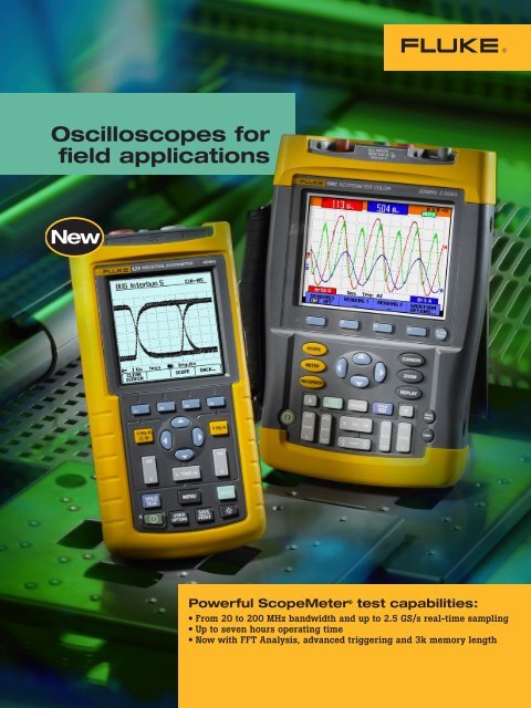
Oscilloscopes for<br />
field applications<br />
Powerful ScopeMeter ® test capabilities:<br />
• From 20 to 200 MHz bandwidth and up to 2.5 GS/s real-time sampling<br />
• Up to seven hours operating time<br />
• Now with FFT Analysis, advanced triggering and 3k memory length
All this power in your hand<br />
ScopeMeter ® 190C and 190B Series:<br />
Speed, performance and analysis power<br />
For the more demanding applications, the ScopeMeter 190 Series highperformance<br />
oscilloscopes offer specifications usually found on top-end bench<br />
instruments. With up to 200 MHz bandwidth, 2.5 GS/s real-time sampling and<br />
a deep memory of 27,500 points per input, they’re ideal for engineers who<br />
need the full capabilities of a high-performance oscilloscope in a handheld,<br />
battery powered instrument.<br />
• Dual-input – 200, 100 or 60 MHz<br />
bandwidth<br />
• Up to 2.5 GS/s real-time sampling<br />
per input<br />
• Choice between a high-resolution<br />
color display (190C Series) or blackand-white<br />
display (190B Series)<br />
• Connect-and-View automatic triggering<br />
and a full range of manual<br />
trigger modes<br />
• Digital Persistence mode for analyzing<br />
<strong>com</strong>plex dynamic waveforms<br />
like on an analog scope<br />
• Fast display update rate for seeing<br />
dynamic behavior instantaneously<br />
• Automatic capture and replay of<br />
100 screens<br />
• 27,500 points per input record<br />
length using ScopeRecord mode<br />
• TrendPlot paperless chart recorder<br />
for trend analysis up to 22 days<br />
• Waveform reference for visual<br />
<strong>com</strong>parisons and automatic pass/fail<br />
testing of waveforms<br />
• V pwm function for motor drive and<br />
frequency inverter applications<br />
• Up to 1000 V independently<br />
floating isolated inputs for<br />
1000 V CAT II and 600 V CAT III<br />
safety certification<br />
• Four hours rechargeable NiMH<br />
battery pack<br />
See an on-line demonstration,<br />
go to www.fluke.<strong>com</strong>/scopemeter<br />
High sampling rates give you the required<br />
resolution for detailed signal analysis.<br />
See what’s really happening<br />
With a maximum real-time sampling<br />
rate of 2.5 GS/s per input, you can<br />
see what really happens, with 400 ps<br />
resolution. Both inputs have their own<br />
digitizer, so you can simultaneously<br />
acquire two waveforms and analyze<br />
them with the highest resolution<br />
and detail. If an anomaly flashes<br />
by on the screen, just press the Replay<br />
button to see it again. And thanks to<br />
the wider screen, you will always see a<br />
12 divisions time window giving a far<br />
better overview of what’s happening<br />
both before and after the trigger event!<br />
Thanks to the deeper memory, very small parts<br />
of the waveform can be studied in full detail<br />
using “zoom”.<br />
Deeper waveform<br />
acquisition memory<br />
The waveform memory of all oscilloscopes<br />
in both the 190B and 190C<br />
Series has been enlarged to allow as<br />
many as 3000 samples per channel to<br />
be acquired. You can use the ZOOM<br />
function to find tiny details in a long<br />
waveform, for example, the color burst<br />
in a video signal or a single impulse in<br />
a <strong>com</strong>plex data-stream. All models also<br />
allow the high-resolution waveforms to<br />
be transferred to a PC for later detailed<br />
analysis using FlukeView ® ScopeMeter<br />
software.<br />
Easier identification of<br />
traces, everywhere<br />
The full-color display makes identification<br />
of individual waveforms easier,<br />
particularly when displaying large<br />
amplitude or multiple overlapping waveforms<br />
on screen. On-screen color labels,<br />
measurements and warnings are clearly<br />
linked to specific waveforms.<br />
See dynamic signal behavior<br />
instantaneously<br />
The Digital Persistence mode (Fluke<br />
190C) helps to find anomalies and to<br />
analyze <strong>com</strong>plex dynamic signals by<br />
showing the waveforms amplitude<br />
distribution over time. Digital Persistence<br />
uses multiple intensity levels and<br />
user selectable decay time—it’s as<br />
if you’re looking at the display of an<br />
analog, real-time oscilloscope! The<br />
fast display update rate that’s standard<br />
on all models reveals signal changes<br />
instantaneously, useful for instance<br />
when making adjustments to a system<br />
under test.<br />
Frequency Spectrum shows an overview of<br />
frequencies contained in a signal.<br />
Frequency spectrum analysis<br />
All 190C color ScopeMeter models now<br />
include Frequency Spectrum Analysis<br />
functionality based on Fast Fourier<br />
Transformation (FFT) analysis as a<br />
standard feature. This enables you<br />
to identify the individual frequency<br />
<strong>com</strong>ponents contained in a signal.<br />
The spectrum analysis function is<br />
also handy for revealing the effects<br />
of vibration, signal interference or<br />
crosstalk. An automatic window<br />
function assures optimal windowing,<br />
although you may manually<br />
select your preferred time window.<br />
Dual-slope triggering used to capture the<br />
eye-pattern on a digital datastream.<br />
Advanced trigger modes<br />
The ScopeMeter 190 Series simplifies<br />
triggering with Connect-and-View<br />
automatic triggering. Two new modes<br />
—“n-cycle triggering” and “dual-slope<br />
triggering”—have been added to the<br />
Fluke 190C Series to help you isolate<br />
the phenomena of interest. N-cycle<br />
triggering ensures you get a stable<br />
live image of a signal, for example,<br />
in-frequency dividers and clocked<br />
(synchronous) digital systems, or<br />
to synchronize on bursts of pulses.<br />
Dual-slope triggering enables the oscilloscopes<br />
to trigger on both rising and<br />
falling edges alike. This means that any<br />
edge in the signal will act as a trigger<br />
event and initiate a new waveform<br />
acquisition, a most useful capability<br />
when making eye-patterns from<br />
digital data-streams, or in conjunction<br />
with single-shot phenomena. Manual<br />
modes include edge, delay, video and<br />
pulse width triggering. A fully isolated<br />
external trigger input is included for<br />
troubleshooting time relationships<br />
between two input signals synchronized<br />
to a third signal.<br />
<br />
Digital Persistence mode gives analog scopelike<br />
display of <strong>com</strong>plex and modulated signals.
ScopeMeter ® 190 Series<br />
ScopeMeter ® 120 and 190 Series <strong>com</strong>mon functions<br />
Software and special value kits.<br />
<br />
The inrush current is measured on the part of<br />
the waveform enclosed by the cursors.<br />
Cursor-limited<br />
automatic measurement<br />
ScopeMeter 190C and 190B features<br />
30 automatic measurements, cursors,<br />
zoom and real-time clock. Now automatic<br />
power and Vrms-measurements<br />
can be performed on a specific, user<br />
identified portion of the waveform<br />
using the cursors of the Fluke 190C<br />
to define the time-window of interest.<br />
In this way, the ScopeMeter 190C<br />
measures the power within a specified<br />
time span, or the rms-value of a voltage<br />
during a dedicated period of time.<br />
Pass/Fail testing of actual signal against a<br />
reference template<br />
Waveform Pass/Fail Testing<br />
“Waveform reference” allows an acquired<br />
trace to be stored and designated “reference<br />
trace” for visual <strong>com</strong>parisons, or it<br />
can be used as the reference for automatic<br />
“Pass/Fail” testing (190C). Up to<br />
100 individually matching (“Pass”) or<br />
non-matching (“Fail”) waveforms can be<br />
stored in the replay memory, allowing<br />
you to monitor your system‘s behavior<br />
over a long period of time, without<br />
having to be present!<br />
Automatic capture and replay<br />
of 100 screens<br />
Scope users know how frustrating it is to<br />
see a one-time anomaly flash. Not with<br />
the ScopeMeter 190 Series! Now you can<br />
look back in time with a touch of the<br />
replay button. In normal use, the instrument<br />
continuously memorizes the last<br />
100 screens. Each time a new screen is<br />
acquired, the oldest is discarded. At any<br />
moment, you can “freeze” the last 100<br />
screens and scroll through picture-bypicture<br />
or replay as a “live” animation.<br />
Cursors can be used for further analysis.<br />
Use the advanced trigger capabilities<br />
to capture up to 100 specific events.<br />
Two sets of 100 captured screens with<br />
individual time stamps can be stored for<br />
later recall or download to a PC.<br />
Measure from mV to kV—<br />
fully isolated and safely!<br />
The ScopeMeter 190C and 190B series<br />
have three independently floating<br />
isolated inputs. While conventional<br />
oscilloscopes can only make measurements<br />
referenced to the line power<br />
ground, measurements on each of the<br />
Fluke ScopeMeter 190 series inputs<br />
can be referenced to a different “low”<br />
level. This enables measurements in<br />
mixed circuits having different ground<br />
references, and also eliminates the risk<br />
of accidental ground short circuits. All<br />
inputs are safety certified for measurements<br />
in 1000 V CAT II and 600 V<br />
CAT III environments. And the standard<br />
probes cover a wide application range<br />
from mV to kV, making the 190C and<br />
190B ScopeMeter ideal for micro electronics<br />
to electrical applications.<br />
Vpwm measures effective voltage on motor drive<br />
and frequency inverter outputs.<br />
Use the 27,500 points memory of ScopeRecord<br />
and zoom in for maximum detail.<br />
Deep memory for high-resolution<br />
ScopeRecord<br />
The ScopeRecord memory stores 27,500<br />
points per input or more, for highresolution<br />
recording of events up to 48<br />
hours, and captures fast intermittents<br />
and glitches as short as 50 ns. This<br />
continuous roll mode stores events like<br />
motion profiles, UPS, power supply and<br />
motor start-ups. All models also have<br />
a “Stop-on-Trigger” in the ScopeRecord<br />
mode, allowing the ScopeMeter to store<br />
waveform data until the instrument<br />
is triggered or until a repetitive trigger<br />
signal is interrupted. This way,<br />
the instrument will automatically<br />
recognize a power failure and store the<br />
waveform data preceding it. With<br />
100 x zoom, you can look at the smallest<br />
details, like individual power cycles.<br />
Two of these 27,500 point recordings<br />
can be stored for later analysis.<br />
Cursors and zoom featured by the 190 Series<br />
help you to analyze the captured TrendPlot.<br />
Use TrendPlot to help<br />
find intermittents, fast<br />
The toughest faults to find are those<br />
that happen only once in a while<br />
—intermittents. They can be caused by<br />
bad connections, dust, dirt, corrosion<br />
or simply broken wiring or connectors.<br />
Other factors, like line outages and sags<br />
or the starting and stopping of a motor,<br />
can also cause a machine to stop. You<br />
may not be around to see it your Fluke<br />
ScopeMeter will. In this “paperless<br />
recorder” mode, you can plot the minimum<br />
and maximum peak values and<br />
average over time up to 16 days. The<br />
two inputs can plot any <strong>com</strong>bination<br />
of volts, amps, temperature, frequency<br />
and phase – with time and date stamp<br />
—to help lead you to the cause of those<br />
faults quickly.<br />
ScopeMeter special value kit<br />
FlukeView Software and the optically isolated<br />
interface cable <strong>com</strong>e as separate items, or as part of<br />
the special value SCC-Kit. This kit contains:<br />
• FlukeView Software (SW90W)<br />
• Optically Isolated Interface Cable (for USB)<br />
• Protective Hard-Shell Carrying Case (C190 or C120)<br />
The SCC-kit can be ordered separately, or<br />
with the main instrument by adding an “S”<br />
to the main instrument type number, e.g.,<br />
Fluke 199C/S (see Ordering Information<br />
on back cover for more detailed information).<br />
Connect-and-View captures even<br />
the most <strong>com</strong>plex motor drive signals.<br />
Connect-and-View<br />
triggering for an<br />
instant, stable display<br />
Scope users know how difficult triggering<br />
can be. Incorrect settings show<br />
unstable and sometimes incorrect<br />
results. The unique Connect-and-View<br />
function recognizes signal patterns and<br />
automatically sets up correct triggering.<br />
It provides a stable, reliable and repeatable<br />
display of virtually any signal,<br />
including motor drive and control<br />
signals, without touching a button.<br />
Signal changes are instantly recognized<br />
and settings adjusted for a stable<br />
display. Benefit from the speed and<br />
convenience when measuring a number<br />
of test-points in quick succession.<br />
SCC190 Kit<br />
SCC120 Kit<br />
FlukeView ®<br />
Software for<br />
documenting,<br />
archiving and<br />
analysis<br />
FlukeView for Windows ®<br />
helps you get more out of<br />
your ScopeMeter by:<br />
• Documenting – transfer waveforms,<br />
screens and measurement data from<br />
the ScopeMeter to a PC. Print or<br />
import the data into your report.<br />
• Adding user text to individual<br />
ScopeMeter settings – providing<br />
guidance to the operator when<br />
recalling a set-up.<br />
• Archiving – create a library of<br />
waveforms with your <strong>com</strong>ments<br />
for easy reference and <strong>com</strong>parison.<br />
Store <strong>com</strong>plete Replay cycles for<br />
analysis of waveform changes.<br />
Store <strong>com</strong>plete memory content of<br />
the ScopeMeter on your PC for<br />
back-up purposes.<br />
• Waveform <strong>com</strong>pare – store reference<br />
waveforms, add operator<br />
instructions, and send both to the<br />
ScopeMeter for waveform <strong>com</strong>parison<br />
and “Pass/Fail” testing.<br />
• Analysis – use cursors, perform<br />
spectrum analysis or export data to<br />
other analysis programs.<br />
• Connection to a PC via an optically<br />
isolated interface cable –<br />
Software and cable <strong>com</strong>e as separate<br />
items or as part of a special value<br />
kit. This kit also includes a protective<br />
hard shell carrying case for safe and<br />
convenient storage of instrument and<br />
accessories.
New! Fluke 125<br />
Industrial ScopeMeter ®<br />
ScopeMeter ® 120 Series:<br />
As simple as one-two-three<br />
The <strong>com</strong>pact ScopeMeter 120 Series is the rugged solution for industrial troubleshooting<br />
and installation applications. It’s a truly integrated test tool, with<br />
oscilloscope, multimeter and “paperless” recorder in one affordable, easy-touse<br />
instrument. Find answers fast to problems in machinery, instrumentation,<br />
control and power systems.<br />
• Dual-input 40 MHz or 20 MHz<br />
digital oscilloscope<br />
• Two 5,000-count true-rms digital<br />
multimeters<br />
• Automatic measurements<br />
• A dual-input TrendPlot recorder<br />
• Connect-and-View trigger<br />
simplicity for hands-off operation<br />
• Shielded test leads for oscilloscope,<br />
resistance and continuity<br />
measurements<br />
• 10:1 Voltage Probe included with<br />
Fluke 124 and 125 for reduced<br />
circuit loading<br />
• Up to seven hours battery operation<br />
• 600 V CAT III safety certified<br />
• Optically isolated interface<br />
• Rugged <strong>com</strong>pact case<br />
• New Fluke 125 gives bus health and<br />
power measurements<br />
In today’s <strong>com</strong>plex systems, a meter<br />
measurement just doesn’t give enough<br />
detail to determine the cause of a fault.<br />
Signal anomalies, dropouts and glitches<br />
that might cause a machine to go down<br />
are best captured with an oscilloscope.<br />
The ScopeMeter 120 Series meets<br />
today’s need of simultaneously measuring<br />
and checking waveforms. The<br />
unique Connect-and-View triggering<br />
automatically displays stable waveforms<br />
of virtually any signal. It really<br />
is as easy as one-two-three!<br />
Dual-input measurement shows both meter<br />
reading and waveform at the same time.<br />
Scope mode<br />
With bandwidth of 20 MHz (Fluke 123)<br />
or 40 MHz (Fluke 124, 125) the<br />
Fluke 120 Series will capture and<br />
display almost any waveform found<br />
in today’s state-of-the-art industrial<br />
electronic or electro-mechanical<br />
applications. Even <strong>com</strong>plex signals<br />
like variable frequency motor drives.<br />
With Connect-and-View, it is as<br />
simple as connecting to the test point<br />
and letting the scope do the rest.<br />
Meter mode<br />
You don’t need to reach for another<br />
test tool to make a simple resistance<br />
measurement. The ScopeMeter 120<br />
Series includes a multimeter on each<br />
input. Measure volts (ac or dc), resistance,<br />
capacitance, current via external<br />
clamp or shunt, temperature using<br />
an adapter or <strong>com</strong>mon time related<br />
measurements like frequency, duty<br />
cycle and more.<br />
Working under time pressure and in<br />
cramped or difficult-to-reach locations<br />
means you want to focus on the job at<br />
hand, not on the test tool in your hand.<br />
That’s why the ScopeMeter 120 Series<br />
has Connect-and-View automatic triggering.<br />
You don’t have to worry about<br />
triggering and instrument settings and<br />
you have all the information on screen<br />
to do the job right.<br />
Battery powered mobility<br />
Up to seven hours of battery operation<br />
frees you from mains outlets for true<br />
on-the-move working. The handheld<br />
format and the weight of just 1.2 kg<br />
(2.64 lbs) make the instrument easy<br />
to carry and to fit <strong>com</strong>fortably in your<br />
hand. The rugged and drip proof case<br />
assures long life and reliable operation<br />
in the harshest industrial environments.<br />
(See technical specifications for<br />
details on battery life.)<br />
Floating measurements,<br />
safety certified<br />
While conventional oscilloscopes can<br />
only make measurements referenced to<br />
power line ground, the Fluke 120 Series<br />
makes floating measurements so there’s<br />
no risk of an accidental ground short<br />
circuit when making a connection.<br />
The Fluke ScopeMeter 120 Series<br />
test tools and the included shielded test<br />
leads are safety certified for measurements<br />
on 600 V CAT III industrial<br />
power systems. Using the VPS40 probe,<br />
measurements up to 1000 V CAT II are<br />
fully supported. Via the optically isolated<br />
interface, the ScopeMeter 120 can be<br />
safely connected to a printer for direct<br />
print-out or to a PC for later analysis<br />
and documentation using FlukeView ®<br />
Software (for additional details about<br />
FlukeView software see page 5).<br />
Built to stand up to<br />
harsh environments<br />
The 120 Series Scopemeter is built to<br />
hold up to every day use in the harshest<br />
of industrial environments. The<br />
case has been designed to withstand<br />
extreme shock of vibration levels<br />
tested to MIL-T-28800E Standards. The<br />
ScopeMeter is also rated IP51, dust and<br />
drip proof according to IEC 529.<br />
Fluke 125 is the ScopeMeter of<br />
choice for the maintenance engineer<br />
who deals with industrial machinery<br />
and the industrial network connecting<br />
his plant processing equipment<br />
and machinery.<br />
The Fluke 125 has all the functionality<br />
of the 124, plus it <strong>com</strong>es with the<br />
following extensions:<br />
• Bus Health mode gives a clear<br />
“Good” / “Bad” indication for the<br />
electrical signals on industrial buses<br />
and networks, such as Foundation<br />
Fieldbus CAN-bus, Profibus, Ethernet,<br />
RS-232 and many more. The<br />
Fluke 125 validates the quality of<br />
the electrical signals on a network<br />
segment. It checks the signal levels<br />
and speed, transition times and<br />
distortion, and <strong>com</strong>pares these to<br />
the appropriate standards to help<br />
you find errors like improper cable<br />
connections and terminators. It helps<br />
you find the source of error in case<br />
<strong>com</strong>munication <strong>com</strong>es to a halt.<br />
All the <strong>com</strong>monly found industrial<br />
network types are supported!<br />
Bus Health mode<br />
allows for an<br />
analysis of the<br />
signal quality<br />
on industrial<br />
network,<br />
<strong>com</strong>paring<br />
measured<br />
signals to the<br />
standards’<br />
signal<br />
requirements.<br />
• Power measurements for single<br />
phase and balanced three-phase<br />
systems. The Fluke 125 can display<br />
the Total Power (Watts), Apparent<br />
Power (VA), Reactive Power (VAR)<br />
and the Power Factor (PF), over a<br />
wide range of applied frequencies,<br />
including those seen with motor<br />
drives and inverters. As a result, you<br />
are able to easily see the effects on<br />
the various power measurements<br />
during start-up or under changing<br />
operational conditions. A current<br />
clamp is included as a standard.<br />
• Harmonics mode graphically<br />
displays harmonics up to the 33rd<br />
harmonic to assist in fault-finding,<br />
e.g. with large non-linear loads.<br />
See the technical datasheet at http://<br />
us.fluke.<strong>com</strong>/usen/products/Fluke+120.<br />
htm for more details on the Fluke 125.
Selection Table<br />
120 and 190 Series ScopeMeter ® Test Tools<br />
Bandwidth<br />
Max. real time sample rate<br />
Equivalent time sample rate<br />
Max. record length (per input)<br />
Number of inputs<br />
Input sensitivity<br />
Independently floating<br />
isolated inputs<br />
Display and Display Modes<br />
Display<br />
Persistence<br />
Envelop Mode<br />
Waveform <strong>com</strong>pare<br />
FFT<br />
Pass/Fail testing<br />
Triggering<br />
Connect-and-View Triggering<br />
Edge, single, free run<br />
Video<br />
Video line select<br />
Pulse width<br />
External<br />
Advanced Functions<br />
Cursors<br />
Zoom<br />
Dual Input TrendPlot<br />
ScopeRecord Mode<br />
Automatic capture and replay<br />
of last 100 screens<br />
Bus Health test mode<br />
Advanced Power<br />
Measurements<br />
Waveform mathematics<br />
Save set-ups and screens<br />
True-rms multimeter<br />
Safety, Power and Warranty<br />
Safety (EN61010-1)<br />
Battery<br />
Line power<br />
PC and printer interface<br />
Warranty<br />
190C ScopeMeter Series 190B ScopeMeter Series 120 Series<br />
Fluke 199C Fluke 196C Fluke 199B Fluke 196B Fluke 192B Fluke 125 Fluke 124 Fluke 123<br />
200 MHz 100 MHz 200 MHz 100 MHz 60 MHz 40 MHz 40 MHz 20 MHz<br />
2.5 GS/s 1.0 GS/s 2.5 GS/s 1.0 GS/s 500 MS/s 25 MS/s 25 MS/s 25 MS/s<br />
(covered by real time sample rate) 2.5 GS/s 2.5 GS/s 1.25 GS/s<br />
3000 points 512 points (min/max pairs)<br />
2 scope inputs, 1 DMM input (all fully isolated from each other) 2 scope or DMM inputs<br />
2 mV/div. to 100 V/div. 5 mV/div. to 100 V/div. 5 mV/div. to 50 V/div.<br />
• •<br />
–<br />
Color Monochrome Monochrome<br />
Digital persistence with<br />
On/Off –<br />
variable decay<br />
• • •<br />
visual + automatic visual only –<br />
•<br />
–<br />
harmonics<br />
mode<br />
–<br />
• – –<br />
• • •<br />
•<br />
–<br />
• •<br />
Using optional ITP120<br />
• • –<br />
•<br />
–<br />
• • –<br />
• •<br />
–<br />
– – • –<br />
• • •<br />
– –<br />
• • –<br />
10 10 20 20 10<br />
5000 counts, measures volts – amps – ohms – continuity – diode – temperature<br />
1000 V CAT II / 600 V CAT III certified 600 V CAT III certified (1)<br />
4 hours, NiMH 7 hours, NiMH<br />
Adapter/battery charger included<br />
Using optional Optically Isolated interface cable (either RS-232 or USB) or PAC91 printer adapter cable<br />
Three years on instrument / One year on standard accessories<br />
(1)<br />
Maximum input voltage 1000 V CAT II with VPS40, 40 MHz, 10:1 Voltage Probe (standard included with Fluke 125 and Fluke 124)<br />
Detailed technical specifications and optional accessories can be found in the technical datasheet and on the Fluke web site.<br />
Ordering information<br />
Fluke 199C Color ScopeMeter (200 MHz / 2.5 GS/s)<br />
Fluke 199C/S Color ScopeMeter (200 MHz / 2.5 GS/s) + SCC190<br />
Fluke 196C Color ScopeMeter (100 MHz / 1 GS/s)<br />
Fluke 196C/S Color ScopeMeter (100 MHz / 1 GS/s) + SCC190<br />
Fluke 199B ScopeMeter (200 MHz / 2.5 GS/s)<br />
Fluke 199B/S ScopeMeter (200 MHz / 2.5 GS/s) + SCC190<br />
Fluke 196B ScopeMeter (100 MHz / 1 GS/s)<br />
Fluke 196B/S ScopeMeter (100 MHz / 1 GS/s) + SCC190<br />
Fluke 192B ScopeMeter (60 MHz / 500 MS/s)<br />
Fluke 192B/S ScopeMeter (60 MHz / 500 MS/s) + SCC190<br />
Fluke 125<br />
Industrial ScopeMeter (40 MHz, with Bus Health)<br />
Fluke 125/S Industrial ScopeMeter (40 MHz, Bus Health) + SCC120 kit)<br />
Fluke 124<br />
Industrial ScopeMeter (40 MHz)<br />
Fluke 124/S Industrial ScopeMeter (40 MHz) + SCC120 kit<br />
Fluke 123<br />
Industrial ScopeMeter (20 MHz)<br />
Fluke 123/S Industrial ScopeMeter (20 MHz) + SCC120 kit<br />
SCC190<br />
FlukeView ® Software + Cable + Case (190 Series)<br />
SCC120<br />
FlukeView ® Software + Cable + Case (120 Series)<br />
OC4USB<br />
Optically-isolated USB-interface cable<br />
PM9080<br />
Optically-isolated RS-232 adapter/cable<br />
SW90W FlukeView ® ScopeMeter Software for Windows ®<br />
• ScopeMeter test tools <strong>com</strong>e standard with a <strong>com</strong>plete accessory package including line<br />
voltage adapter and battery pack (installed). ScopeMeter 190B and 190C Series <strong>com</strong>e<br />
with probes, probe accessories and multimeter test leads.<br />
• Optional accessories ordering information can be found in the technical datasheet or<br />
on the Fluke web site.<br />
Fluke. Keeping your world up and running.<br />
Authorised Distributor:<br />
46, Jalan SS 22/21, Damansara Jaya,<br />
47400 Petaling Jaya, Selangor Darul Ehsan, Malaysia.<br />
Email: info@ampmech.<strong>com</strong><br />
Web access: http://www.ampmech.<strong>com</strong>