Electronic Relays, Relay, HMI, Control, PLCs ... - Moeller Electric Parts
Electronic Relays, Relay, HMI, Control, PLCs ... - Moeller Electric Parts
Electronic Relays, Relay, HMI, Control, PLCs ... - Moeller Electric Parts

Create successful ePaper yourself
Turn your PDF publications into a flip-book with our unique Google optimized e-Paper software.
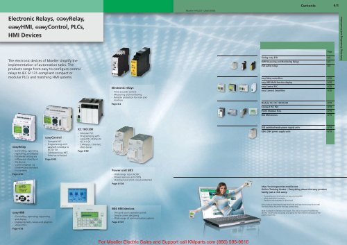
<strong>Electronic</strong> <strong><strong>Relay</strong>s</strong>, <strong>Relay</strong>,<br />
<strong>HMI</strong>, <strong>Control</strong>, <strong>PLCs</strong>,<br />
<strong>HMI</strong> Devices<br />
The electronic devices of <strong>Moeller</strong> simplify the<br />
implementation of automation tasks. The<br />
products range from easy to confi gure control<br />
relays to IEC 61131-compliant compact or<br />
modular <strong>PLCs</strong> and matching <strong>HMI</strong> systems.<br />
<strong>Relay</strong><br />
- <strong>Control</strong>ling, operating,<br />
regulating, and display<br />
- Parameter setting via<br />
software or directly on<br />
the device<br />
- Communication via<br />
Ethernet and standard<br />
bus systems<br />
Page 4/30<br />
<strong>HMI</strong><br />
- <strong>Control</strong>ling, operating, regulating<br />
and display<br />
- Displaying texts, values and graphics<br />
- Value entry<br />
Page 4/36<br />
<strong>Control</strong><br />
- Compact PLC<br />
- Programming with<br />
easySoft-CoDeSys to<br />
IEC 61131<br />
- CANopen/easy-NET,<br />
Ethernet on board<br />
Page 4/40<br />
XC 100/200<br />
- Modular PLC<br />
- Programming with<br />
easySoft-CoDeSys to<br />
IEC 61131<br />
- CANopen, Ethernet,<br />
Web-Server<br />
Page 4/80<br />
<strong>Electronic</strong> relays<br />
- Time accurate control<br />
- Measuring and monitoring<br />
- Reliable protection for man and<br />
machine<br />
Page 4/2<br />
Power unit SN3<br />
- Wide range input AC/DC<br />
- Power reserves up to 50%<br />
- Overload and short-circuit protected<br />
Page 4/106<br />
MI4 <strong>HMI</strong> devices<br />
- Text and touch operator panels<br />
- Simple screen designing<br />
- Wide range of communication options<br />
Page 4/101<br />
<strong>Moeller</strong> HPL0211-2007/2008<br />
For <strong>Moeller</strong> <strong>Electric</strong> Sales and Support call KMparts.com (866) 595-9616<br />
Contents 4/1<br />
Timing relay ETR 4/2<br />
EMR Measuring and Monitoring <strong><strong>Relay</strong>s</strong> 4/2<br />
ESR safety relays 4/2<br />
http://trainingscenter.moeller.net<br />
Online Training Center – Everything about the easy product<br />
family just a click away:<br />
- Comprehensive information on easy and easy<strong>HMI</strong><br />
- Many application examples<br />
- Ready-to-use programs for download<br />
Visit us also at: http://www.easy-forum.net and http://www.easy-forum.net/<br />
The fi rst offi cial forum for the easy control relay.<br />
Note: Available in German and English. This link is not part of moeller.net<br />
<strong>Moeller</strong> GmbH does not accept any liability for the content and layout of the<br />
pages linked here.<br />
Page<br />
easy <strong>Relay</strong> controllers 4/28<br />
easy <strong>HMI</strong> Multi-function display 4/28<br />
easy <strong>Control</strong> PLC 4/28<br />
easy Connect SmartWire 4/28<br />
Modular PLC XC 100/XC200 4/79<br />
Compact PLC PS4 4/79<br />
PS416 Modular <strong>PLCs</strong> 4/79<br />
MI4 <strong>HMI</strong> devices 4/79<br />
SN3 switched-mode power supply units 4/79<br />
GD4, GW4 power supply units 4/79<br />
Switching, <strong>Control</strong>ling and Visualisation
<strong>Electronic</strong> relays<br />
4/2<br />
Contents<br />
<strong>Moeller</strong> HPL0211-2007/2008<br />
http://catalog.moeller.net<br />
Page<br />
<strong>Electronic</strong> relays 4/3<br />
Ordering 4/3<br />
Timing relays 4/3<br />
Description 4/6<br />
Safety relays 4/6<br />
Ordering 4/7<br />
Safety relay 4/7<br />
Measuring and Monitoring <strong><strong>Relay</strong>s</strong> 4/8<br />
Engineering 4/11<br />
Tripping characteristics 4/11<br />
Flow Diagrams 4/12<br />
Technical data 4/14<br />
Timing relay 4/14<br />
Safety relay 4/16<br />
Current monitoring relays 4/20<br />
Phase sequence monitoring relays 4/21<br />
Phase monitoring relays 4/22<br />
Phase imbalance monitors 4/24<br />
Liquid level monitoring relays 4/25<br />
Insulation monitoring relays 4/26<br />
Dimensions 4/27<br />
For <strong>Moeller</strong> <strong>Electric</strong> Sales and Support call KMparts.com (866) 595-9616
http://catalog.moeller.net <strong>Moeller</strong> HPL0211-2007/2008<br />
Rated operational<br />
current AC-11<br />
220 V<br />
230 V<br />
240 V<br />
380 V<br />
400 V<br />
440 V<br />
Conventional<br />
thermal current<br />
Ith<br />
Ie Ie A<br />
A A<br />
Time range Part no.<br />
Article no.<br />
Timing relays, On-delayed<br />
3 3 6 1.5 – 30 s DILET11-30-A<br />
048878<br />
3 3 6 1.5 – 30 s DILET11-30-W<br />
048904<br />
3 3 6 0.05 – 1 s DILET11-M-A<br />
0.15 – 3 s 048886<br />
3 3 6 0.5 – 10 s<br />
3 – 60 s<br />
0.15 – 3 min<br />
0.5 – 10 min<br />
3 – 60 min<br />
0.15 – 3 h<br />
0.5 – 10 h<br />
3 – 60 h<br />
DILET11-M-W<br />
048891<br />
Multi-function relay with connection for remote potentiometer<br />
Notes<br />
3 3 6 0.05 – 1s DILET70-A<br />
0.15 – 3 s 048893<br />
3 3 6 0.5 – 10 s<br />
3 – 60 s<br />
0,15 – 3 min<br />
0.5 – 10 min<br />
3 – 60 min<br />
0.15 – 3 h<br />
0.5 – 10 h<br />
3 – 60 h<br />
DILET70-W<br />
048899<br />
Price<br />
see price<br />
list<br />
Ordering<br />
Timing relays<br />
Std. pack Function<br />
Terminal marking according to EN 50042<br />
1 off fixed<br />
11, On-delayed<br />
fixed<br />
11, On-delayed<br />
Part no. suffix Actuating voltage<br />
V DC V AC<br />
-A 24 – 240 24 – 240, 50/60 Hz<br />
-W – 400, 50/60 Hz<br />
Permissible cable length Connection to<br />
Cable unscreened, with cable cross-section 0.5 – 1.5 mm Y1/Y2, Z1/Z2<br />
Two-core cable 250 m<br />
Two-core cable in the same cable duct with mains cable, 50/60 Hz 50 m<br />
Accessories Page<br />
Time functions a Engineering<br />
Sealable shroud a 5/6<br />
Potentiometer a 2/19<br />
Screw adapter a 4/10<br />
Blade terminals a 2/39<br />
A1<br />
A2<br />
A1<br />
A2<br />
1 off Adjustable<br />
11, On-delayed<br />
1 off 21, Fleeting contact on energization<br />
42, Flashing<br />
81, Pulse generating<br />
ON-OFF<br />
Z1<br />
Z2<br />
A1<br />
A2<br />
15<br />
16 18<br />
15<br />
16 18<br />
15<br />
16 18<br />
Adjustable<br />
12, Off-delayed<br />
16, On- and Off-delayed<br />
22, Fleeting contact on de-energization<br />
82, Pulse shaping<br />
ON-OFF<br />
Z1<br />
Y1<br />
Y2<br />
DILET...<br />
For <strong>Moeller</strong> <strong>Electric</strong> Sales and Support call KMparts.com (866) 595-9616<br />
Z2<br />
A1<br />
A2<br />
15<br />
16 18<br />
4/3<br />
<strong>Electronic</strong> relays
<strong>Electronic</strong> relays<br />
4/4<br />
Ordering Ordering<br />
Timing relays Timing relays<br />
ETR4..., ETR2... <strong>Moeller</strong> HPL0211-2007/2008<br />
http://catalog.moeller.net http://catalog.moeller.net<br />
<strong>Moeller</strong> HPL0211-2007/2008<br />
ETR4..., ETR2...<br />
Rated operational<br />
current AC-15<br />
230 V 400 V Ith<br />
Ie Ie A<br />
A A<br />
Conventional<br />
thermal current<br />
24 – 240 V AC, 50/60 Hz,<br />
24 – 240 V DC<br />
Time range Part no. Price<br />
Article no. see price<br />
list<br />
ETR4 electronic timing relays, 22.5 mm wide<br />
Star-delta timing relays 3 3 6 3 – 60 s ETR4-51-A<br />
031884<br />
On-delayed 3 3 6 0.05 – 1 s<br />
0.15 – 3 s<br />
0.5 – 10 s<br />
1.5 – 30 s<br />
5 – 100 s<br />
ETR4-11-A<br />
031882<br />
Multi-function relay 3 3 6 15 – 300 s<br />
1.5 – 30 min<br />
15 – 300 min<br />
1.5 – 30 h<br />
5 – 100 h<br />
ETR4-69-A<br />
031891<br />
Multi-function relay<br />
with two changeover<br />
contacts and<br />
connection for<br />
potentiometer. Can be<br />
converted to two timed<br />
contacts or one nondelayed<br />
contact and<br />
one timed contact.<br />
3 3 6 ETR4-70-A<br />
031888<br />
ETR2 electronic timing relays, 17.5 mm wide<br />
On-delay 3 6 0.05 – 1 s ETR2-11<br />
1.5 – 30 s<br />
5 – 100 s<br />
1.5 – 30 min<br />
262684<br />
Off-delay 3 6<br />
5 – 100 min<br />
0.5 – 10 h<br />
5 – 100 h<br />
ETR2-12<br />
262686<br />
Fleeting contact on<br />
energization<br />
Flashing, pulse<br />
generating<br />
flashing, 2 times<br />
(ON/OFF-time variable)<br />
3 6 ETR2-21<br />
262687<br />
3 6 ETR2-42<br />
262688<br />
3 6 ETR2-44<br />
262730<br />
Multi-function relay 3 6 ETR2-69<br />
262689<br />
400 V AC, 50/60 Hz<br />
Part no.<br />
Article no.<br />
ETR4-51-W<br />
031885<br />
ETR4-11-W<br />
031883<br />
ETR4-69-W<br />
031887<br />
Price<br />
see price<br />
list<br />
Std. pack Function Terminal marking<br />
according to EN 50042<br />
1 off Fixed<br />
51, star-delta<br />
Fixed<br />
11, On-delayed<br />
Adjustable<br />
11, on-delayed<br />
21, Fleeting contact on<br />
energization<br />
42, Flashing, pulse<br />
generating<br />
81, Pulse generating<br />
ON-OFF<br />
A2/X1 linked<br />
11, on-delayed<br />
21, Fleeting contact on<br />
energization<br />
42, Flashing, pulse<br />
generating<br />
81, Pulse generating<br />
ON-OFF<br />
A2/X1 not linked<br />
11, on-delayed<br />
21, Fleeting contact on<br />
energization<br />
42, Flashing, pulse<br />
generating<br />
81, Pulse generating<br />
ON-OFF<br />
1 off Fixed<br />
11, on-delayed<br />
Fixed<br />
12, Off-delayed<br />
Fixed<br />
21, Fleeting contact on<br />
energization<br />
fixed<br />
42, Flashing, pulse<br />
generating<br />
fixed<br />
44, Flashing, 2 speeds<br />
can be set to either pulse or<br />
pause starting<br />
Adjustable<br />
11, On-delayed<br />
12, Off-delayed<br />
21, Fleeting contact on<br />
energization<br />
42, Flashing, pulse<br />
generating<br />
Z1<br />
X1<br />
A1<br />
A2 18<br />
A1 15<br />
A2<br />
A1<br />
A2 16<br />
Z2<br />
A1<br />
A2<br />
Z1 Z2<br />
A1<br />
X1<br />
A1<br />
A2<br />
A1<br />
A2<br />
17<br />
16 18<br />
15<br />
15<br />
18<br />
16 18<br />
15<br />
16 18<br />
15<br />
16 18<br />
A2 16 18<br />
A1 15<br />
For <strong>Moeller</strong> <strong>Electric</strong> Sales and Support call KMparts.com (866) 595-9616<br />
A2 16<br />
A1<br />
A2 16<br />
15<br />
15<br />
18<br />
18<br />
28<br />
25<br />
26 28<br />
21<br />
22 24<br />
Function Terminal marking<br />
according to EN 50042<br />
Adjustable<br />
12, Off-delayed<br />
16, On- and Off-delayed<br />
22, Fleeting contact on deenergization<br />
82, Pulse shaping<br />
ON-OFF<br />
A2/X1 linked<br />
12, Off-delayed<br />
16, On- and Off-delayed<br />
22, Fleeting contact on deenergization<br />
82, Pulse shaping<br />
ON-OFF<br />
A2/X1 not linked<br />
12, Off-delayed<br />
16, On- and Off-delayed<br />
22, Fleeting contact on deenergization<br />
82, Pulse shaping<br />
ON-OFF<br />
Adjustable<br />
22, Fleeting contact on deenergization<br />
82, Pulse shaping<br />
82, Pulse shaping<br />
Z1<br />
B1<br />
X1<br />
B1 A1 15<br />
A2<br />
Z2<br />
A1<br />
A2<br />
Z1 Z2<br />
B1 A1<br />
X1<br />
A2<br />
16 18<br />
15<br />
16 18<br />
15<br />
16 18<br />
B1 A1 15<br />
A2<br />
16 18<br />
B1 A1 15<br />
A2<br />
16 18<br />
B1 A1 15<br />
A2<br />
16 18<br />
25<br />
26 28<br />
21<br />
22 24<br />
Notes<br />
Permissible cable Connection to<br />
length<br />
Cable unscreened, with<br />
cable cross-section 0.5<br />
– 1.5 mm2 B1, Z1/Z2<br />
Two-core cable 250 m<br />
Two-core cable in the 50 m<br />
same cable duct with<br />
mains cable, 50/60 Hz<br />
Accessories Page<br />
Time functions a Engineering<br />
Sealable shroud a 5/6<br />
Potentiometer a 2/19<br />
Screw adapter a 4/10<br />
Time functions a Engineering<br />
4/5<br />
<strong>Electronic</strong> relays
<strong>Electronic</strong> relays<br />
4/6<br />
Applications<br />
Description<br />
Safety relay<br />
<strong>Electronic</strong> safety relays are used for monitoring safety-related control systems. The<br />
requirements for the electrical equipment of machines are specified in IEC/EN<br />
60204. The machine operator must assess the risk on his machine according to EN<br />
954-1 and then manufacture the controls accordingly for the corresponding safety<br />
category 1, 2, 3 or 4.<br />
Construction<br />
ESR4…<br />
The electronic safety relay consists of a supply unit, the electronics and 2 redundant<br />
relays with position operating contacts for the enabling and message circuits.<br />
Product range overview<br />
The range includes relays for:<br />
Emergency-Stop circuits<br />
Protective guard monitoring<br />
Monitoring of two-hand controls<br />
Contact expansion modules with and without delay are also available.<br />
<strong>Moeller</strong> HPL0211-2007/2008<br />
Category according to EN 954-1<br />
http://catalog.moeller.net<br />
The electronic safety relays are approved by employer´s liability insurance association<br />
or Technical Monitoring Service (TUV) and their internal assembly corresponds to<br />
the requirements for category 4 according to EN 954-1. Combined with external wiring,<br />
which is the responsibility of the machine operator, the safety relay can be used<br />
for categories 2 to 4.<br />
The electronic safety relays are single-fault proof, i. e. one fault in the safety circuit<br />
(e.g. a short-circuit in the emergency-stop circuit)does not cause hazardous conditions.<br />
EN 954-1 excludes the possibility of two independent faults occurring at the same<br />
time.<br />
Stop category<br />
IEC/EN 60204-1 defines two relevant stop categories for stopping in the event of an<br />
emergency:<br />
• Stop category 0: shut-down by means of immediate removal of the power supply<br />
to the machine actuators.<br />
• Stop category 1: controlled stopping with power available to the machine actuators<br />
to achieve the stop. Power is not removed until the stop is achieved.<br />
Basic devices and expansion modules are available for both categories.<br />
Function<br />
In fault-free operation, following the starting command, the safety circuits are monitored<br />
by the electronics, and the enabling paths are activated via the relays. Following<br />
the switch OFF command, and also in the event of a fault (earth fault, faulty<br />
insulation, wire breakage, etc.), the enabling paths are blocked immediately (Stop<br />
category 0) or with a time delay (Stop category 1) and the motor is disconnected<br />
from the power supply. Since a short circuit in a redundant safety circuit does not<br />
cause a hazardous condition, the fault is not detected until the system is reset, when<br />
switching on is prevented.<br />
Single/dual channel construction<br />
Safety relays for stopping in the event of an emergency and for monitoring of protective<br />
guards are available for single-channel and dual-channel applications. The<br />
single-channel construction enables earth fault monitoring to be implemented for<br />
the safety circuit. The dual-channel application provides a redundant Emergency-<br />
Stop or protective guard monitoring circuit. This allows monitoring for short circuits<br />
and cable insulation faults to be implemented as well. The device can also be used<br />
with or without reset monitoring. Here, the device is not started and enabling paths<br />
switched until the falling edge of the reset pushbutton has been detected. An application<br />
for the device without reset monitoring is for example, for monitoring of<br />
protective doors for an automatic restart.<br />
For <strong>Moeller</strong> <strong>Electric</strong> Sales and Support call KMparts.com (866) 595-9616
http://catalog.moeller.net <strong>Moeller</strong> HPL0211-2007/2008<br />
Actuating<br />
voltage<br />
Approval Category to<br />
EN 954-1<br />
Number of<br />
enabling paths to<br />
IEC/EN 60204<br />
Stop category<br />
Uc 0 1<br />
Safety relays for Emergency-Stop and protective door monitoring<br />
Can be used up to:<br />
prEN ISO 13849-1<br />
PL e (PL =<br />
Performancy level)<br />
EN 61508 SIL 3 (SIL<br />
= Safety integrity<br />
level) EN 62061<br />
SILCL 3 (SILCL =<br />
Safety integrity<br />
level claim limit)<br />
Safety relay<br />
Two-hand relay<br />
24 V DC,<br />
24 V AC,<br />
50/60 Hz<br />
115 V AC,<br />
50/60 Hz<br />
230 V AC,<br />
50/60 Hz<br />
24 V DC,<br />
24 V AC,<br />
50/60 Hz<br />
115 V AC,<br />
50/60 Hz<br />
230 V AC,<br />
50/60 Hz<br />
24 V DC,<br />
24 V AC,<br />
50/60 Hz<br />
24V DC Dual-channel,<br />
Off-delayed,<br />
0.15 – 3 s<br />
24V DC Dual-channel,<br />
Off-delayed,<br />
1.5 – 30 s<br />
24 V DC,<br />
24 V AC,<br />
50/60 Hz<br />
230 V AC,<br />
50/60 Hz<br />
24 V DC,<br />
24 V AC,<br />
50/60 Hz<br />
230 V AC,<br />
50/60 Hz<br />
24 V DC,<br />
24 V AC<br />
50/60 Hz<br />
Contact expansion modules<br />
24 V DC,<br />
24 V AC<br />
50/60 Hz<br />
Notes<br />
Signalling<br />
contacts<br />
Ordering<br />
Safety relay<br />
Part no.<br />
Article no.<br />
Dual-channel 4 3 – – ESR4-NO-30-24VAC-DC<br />
279368<br />
Dual-channel 4 3 – – ESR4-NO-30-115VAC<br />
279410<br />
Dual-channel 4 3 – – ESR4-NO-30-230VAC<br />
279369<br />
Single-channel 2 3 – 1 ESR4-NO-31<br />
214612<br />
Single-channel 2 3 – 1 ESR4-NO-31-115VAC<br />
279367<br />
Single-channel 2 3 – 1 ESR4-NO-31-230VAC<br />
279365<br />
Dual-channel 4 2 – 1 ESR4-NO-21<br />
214613<br />
4 (nondelayed)<br />
3 (delayed)<br />
4 (nondelayed)<br />
3 (delayed)<br />
2 1 – ESR4-NV3-30<br />
214616<br />
2 1 – ESR4-NV30-30 1)<br />
214617<br />
Dual-channel 4 3 – 1 ESR4-NOE-31-24VAC-DC 2)<br />
106843<br />
Dual-channel 4 3 – 1 ESR4-NOE-31-230VAC 2)<br />
106844<br />
Dual-channel 4 4 – – ESR4-NOE-40-24VAC-DC 2)<br />
106845<br />
Dual-channel 4 4 – – ESR4-NOE-40-230VAC 2)<br />
106846<br />
Dual-channel 4 2 – 1 ESR4-NZ-21 3)<br />
214620<br />
Non-delayed 4 4 – 2 ESR4-NE-42 4)<br />
214614<br />
24V DC Off-delayed, tA<br />
= 3 s<br />
4 – 4 2 ESR4-VE3-42 4)<br />
214618<br />
1) Suitable for LS-S-…MT-ZBZ safety position switch with interlocking option.<br />
2) Approved for lifts according to EN 81-1 and furnaces according to EN 50156-1 (Safety-level step 3).<br />
3) Safety category to EN 954-1: The base unit determines the maximum safety category.<br />
4) Stop category to EN 60204: The base unit determines the maximum safety category.<br />
ESR4...<br />
Price<br />
see price<br />
list<br />
For <strong>Moeller</strong> <strong>Electric</strong> Sales and Support call KMparts.com (866) 595-9616<br />
4/7<br />
<strong>Electronic</strong> relays
<strong>Electronic</strong> relays<br />
4/8<br />
Ordering<br />
Measuring and monitoring relays<br />
EMR4...<br />
Description Current<br />
measuring<br />
range<br />
Ih/I=<br />
A<br />
EMR4-I...current monitoring relays, single-phase<br />
• Switching hysteresis adjustable<br />
from 3 – 30 %<br />
• Response delay 0.1 – 30 s<br />
• Monitoring of one upper or lower<br />
limit<br />
• Extension of the measurement<br />
range possible with current<br />
transformers<br />
3 – 30 mA<br />
10 – 100 mA<br />
0.1 – 1 A<br />
0.3 – 1.5 A<br />
1 – 5 A<br />
3 – 15 A<br />
0.3 – 1.5 A<br />
1 – 5 A<br />
3 – 15 A<br />
Description Monitoring<br />
voltage<br />
EMR4-F... phase sequence relays<br />
• Monitors three-phase systems for<br />
phase sequence and phase failure<br />
(< 0.6 x Ue)<br />
• Supply voltage = voltage being<br />
monitored<br />
EMR4-A... phase imbalance monitoring relays<br />
• Monitors three-phase systems for<br />
phase imbalance<br />
• Detects phase failure even at 95%<br />
regeneration of the failed phase<br />
• Response delay: 0.5 s<br />
• Switching threshold adjustable<br />
from 5 – 15 % imbalance<br />
• Phase sequence detection<br />
• Supply voltage = voltage being<br />
monitored<br />
<strong>Moeller</strong> HPL0211-2007/2008<br />
Contact sequence Supply voltage Part no.<br />
Article no.<br />
C<br />
B1 B2 B3<br />
15 25<br />
A1 A2 16 18 26 28<br />
24 – 240 V AC/DC EMR4-I1-1-A<br />
106942<br />
24 – 240 V AC/DC EMR4-I15-1-A<br />
106943<br />
220 – 240 V AC EMR4-I15-1-B<br />
106944<br />
Contact sequence Supply voltage Part no.<br />
Article no.<br />
200 – 500 V AC L1 L2 L3 1115<br />
2125<br />
200 – 500 V AC EMR4-F500-2<br />
221784<br />
380 – 415 V<br />
50 Hz<br />
160 – 300 V<br />
50 Hz<br />
300 – 500 V<br />
50 Hz<br />
Description Response<br />
sensitivity range<br />
O<br />
EMR4-N... liquid level monitoring relays<br />
• Monitors the level of conductive<br />
liquids<br />
• Monitors the ratio of mixtures of<br />
conductive liquids<br />
• Dual-voltage protection against<br />
running dry or overflow<br />
• Monitors the level of conductive<br />
liquids<br />
• Monitors the ratio of mixtures of<br />
conductive liquids<br />
• Selectable On-delay or Off-delay<br />
between 0.5 – 10 s<br />
1216 1418 2226 2428<br />
L1 L2 L3 15<br />
L1 L2 L3<br />
16 18<br />
15 25<br />
16 18 26 28<br />
380 – 415 V<br />
50 Hz<br />
160 – 300 V<br />
50 Hz<br />
300 – 500 V<br />
50 Hz<br />
EMR4-A400-1<br />
221788<br />
EMR4-A300-1-C<br />
290180<br />
EMR4-A500-1-D<br />
290181<br />
Contact sequence Supply voltage Part no.<br />
Article no.<br />
5 kO – 100 kO C MAX MIN 15 220 – 240 V AC EMR4-N100-1-B<br />
221789<br />
250 O – 500<br />
kO<br />
250 O – 500<br />
kO<br />
A1 A2 16<br />
C MAX MIN<br />
18<br />
15 25<br />
A1 A2 16 18 26 28<br />
220 – 240 V AC EMR4-N500-2-B<br />
221790<br />
24 – 240 V AC/DC EMR4-N500-2-A<br />
221791<br />
http://catalog.moeller.net<br />
Price<br />
see price<br />
list<br />
Price<br />
see price<br />
list<br />
Price<br />
see price<br />
list<br />
Std. pack<br />
1 off<br />
1 off<br />
1 off<br />
Std. pack<br />
1 off<br />
1 off<br />
Std. pack<br />
For <strong>Moeller</strong> <strong>Electric</strong> Sales and Support call KMparts.com (866) 595-9616<br />
1 off
http://catalog.moeller.net <strong>Moeller</strong> HPL0211-2007/2008<br />
Monitoring<br />
voltage<br />
Phase monitoring relay EMR4-(A)... RMQ-Titan<br />
Single function • Three-phase<br />
monitoring<br />
– Phase<br />
sequence<br />
– Phase failure<br />
– Overvoltage<br />
– Undervoltage<br />
– Asymmetry<br />
2…15 %<br />
• ON-delay or<br />
OFF-delay<br />
0.1 – 10 s<br />
multifunctional<br />
• Three-phase<br />
monitoring<br />
– Phase<br />
sequence<br />
– Phase failure<br />
– Overvoltage<br />
– Undervoltage<br />
– Asymmetry<br />
2…15 %<br />
• ON-delay or<br />
OFF-delay<br />
0.1 – 10 s<br />
• Power supply<br />
from the<br />
measuring<br />
circuit<br />
• EMR4-AWN...<br />
with neutral<br />
monitoring<br />
300 – 500 V<br />
50/60 Hz<br />
160 – 300 V<br />
50/60 Hz<br />
300 – 500 V<br />
50/60 Hz<br />
380V<br />
50/60Hz<br />
400V<br />
50/60Hz<br />
160 – 300 V<br />
50/60 Hz<br />
300 – 500 V<br />
50/60 Hz<br />
90 – 170 V<br />
50/60 Hz<br />
180 – 280 V<br />
50/60 Hz<br />
Threshold value Contact sequence Supply<br />
voltage<br />
Umin 350 – 430 V AC<br />
Umax 500 – 580 V AC<br />
Umin 160 – 220 V AC<br />
Umax 220 – 300 V AC<br />
Umin 300 – 380 V AC<br />
Umax 420 – 500 V AC<br />
Umin 342 V AC, fixed<br />
Umax 418 V AC, fixed<br />
Umin 360 V AC, fixed<br />
Umax 440 V AC, fixed<br />
Umin 160 – 220 V AC<br />
Umax 220 – 300 V AC<br />
Umin 300 – 380 V AC<br />
Umax 420 – 500 V AC<br />
Umin 90 – 120 V AC<br />
Umax 120 – 170 V AC<br />
Umin 180 – 220 V AC<br />
Umax 240 – 280 V AC<br />
L1 L2 L3<br />
Ordering<br />
Measuring and monitoring relays<br />
15 25<br />
A1 A2 16 18 26 28<br />
L1 L2 L3<br />
L1 L2 L3<br />
L1 L2 L3<br />
15 25<br />
16 18 26 28<br />
15 25<br />
16 18 26 28<br />
15 25<br />
N 16 18 26 28<br />
300 – 500 V<br />
AC<br />
160 – 300 V<br />
50/60 Hz<br />
300 – 500 V<br />
50/60 Hz<br />
380V<br />
50/60Hz<br />
400V<br />
50/60Hz<br />
160 – 300 V<br />
50/60 Hz<br />
300 – 500 V<br />
50/60 Hz<br />
90 – 170 V<br />
50/60 Hz<br />
180 – 280 V<br />
50/60 Hz<br />
Part no.<br />
Article no.<br />
EMR4-W580-2-D<br />
221787<br />
EMR4-W300-1-C<br />
290182<br />
EMR4-W500-1-D<br />
290183<br />
EMR4-W380-1<br />
290184<br />
EMR4-W400-1<br />
290185<br />
EMR4-AW300-1-C<br />
290243<br />
EMR4-AW500-1-D<br />
290244<br />
EMR4...<br />
EMR4-AWN170-1-E<br />
290245<br />
EMR4-AWN280-1-F<br />
290246<br />
Price<br />
see price<br />
list<br />
Std. pack<br />
For <strong>Moeller</strong> <strong>Electric</strong> Sales and Support call KMparts.com (866) 595-9616<br />
1 off<br />
1 off<br />
4/9<br />
<strong>Electronic</strong> relays
<strong>Electronic</strong> relays<br />
4/10<br />
Ordering<br />
measuring and monitoring relay, accessories<br />
Description Insulation<br />
resistance<br />
range<br />
O<br />
EMR-4R... insulation monitoring relays<br />
• Monitors the insulation resistance in nonearthed<br />
DC suppy systems<br />
• Selector switch between open-circuit or<br />
closed-circuit principle<br />
• With test and reset facilities<br />
• Status indication via LEDs<br />
EMR4-PH... sealable shroud<br />
Remote potentiometer, IP66<br />
10 kO; 0.5 W max.<br />
Screw adapter<br />
For screw fixing<br />
EMR4...<br />
• Monitors the insulation resistance<br />
between non-earthed AC suppy systems<br />
and protective conductor/earth<br />
• Tripping function memory<br />
• Insulation monitoring in 1- and 3-phase<br />
AC supply systems<br />
• Test via local test button or remote test/<br />
operation<br />
• Status indication via LEDs to VDE 0413 /<br />
Part 2<br />
<strong>Moeller</strong> HPL0211-2007/2008<br />
Contact sequence Supply<br />
voltage<br />
10 – 110 kO L+ L– 15 24 – 240 V<br />
AC/DC<br />
R <<br />
A1 A2<br />
1 – 110 kO L<br />
R <<br />
15 24 – 240 V<br />
AC/DC<br />
A1 A2<br />
16<br />
16<br />
18<br />
18<br />
Part no.<br />
Article no.<br />
EMR4-RDC-1-A<br />
221792<br />
EMR4-RAC-1-A<br />
221793<br />
Mounting width Part no.<br />
Article no.<br />
mm<br />
22.5 EMR4-PH22<br />
221795<br />
45 EMR4-PH45<br />
221794<br />
For use with Part no.<br />
Article no.<br />
DILET...ETR4-70 M22-R10K<br />
229491<br />
DILET...ETR4-70 M22S-R10K<br />
232233<br />
EWDILETS4-VS3ETR4 CS-TE<br />
095853<br />
http://catalog.moeller.net<br />
Price<br />
see price<br />
list<br />
Price<br />
see price<br />
list<br />
Price<br />
see price<br />
list<br />
Std. pack<br />
1 off<br />
Std. pack<br />
1 off<br />
Std. pack<br />
For <strong>Moeller</strong> <strong>Electric</strong> Sales and Support call KMparts.com (866) 595-9616<br />
1 off<br />
1 off<br />
10 off
http://catalog.moeller.net <strong>Moeller</strong> HPL0211-2007/2008<br />
Load limit curves, 22.5 mm range<br />
AC load (resistive) DC load (resistive)<br />
U<br />
[V]<br />
300<br />
200<br />
100<br />
80<br />
60<br />
50<br />
40<br />
30<br />
20<br />
10<br />
0.1 0.2 0.5 1 2 4 6 10<br />
Derating factor with inductive AC load Contact life<br />
F<br />
1.0<br />
0.9<br />
0.8<br />
0.7<br />
0.6<br />
0.5<br />
Derating factor F with<br />
inductive load<br />
Load limit curves, 45 mm range<br />
AC load (resistive) DC load (resistive)<br />
U<br />
[V]<br />
Derating factor with inductive AC load Contact life<br />
F<br />
400<br />
300<br />
200<br />
100<br />
80<br />
60<br />
I [A]<br />
0.1 0.2 0.3 0.4 0.5 0.6 0.7 0.8 0.9 1.0<br />
40<br />
30<br />
20<br />
cos v<br />
10<br />
0.1 0.2 0.5 1 2 4 6 10<br />
1.0<br />
0.9<br />
0.8<br />
0.7<br />
0.6<br />
0.5<br />
0.1 0.2 0.3 0.4 0.5 0.6 0.7 0.8 0.9 1.0<br />
I [A]<br />
Derating factor F with<br />
inductive load<br />
Overload capacity of EMR4-I… DILET (AC-11)<br />
Current measuring<br />
ranges<br />
EMR4-I1... 3...30 mA<br />
10...100 mA<br />
0.1...1 A<br />
EMR4-I15... 0.3...1.5 A<br />
1...5 A<br />
3...15 A<br />
Input resistance<br />
Ri<br />
3.3 O<br />
1 O<br />
0.1 O<br />
0.05 O<br />
0.01 O<br />
0.0025 O<br />
cos v<br />
Terminal configuration,<br />
measuring<br />
input<br />
B1-C<br />
B2-C<br />
B3-C<br />
B1-C<br />
B2-C<br />
B3-C<br />
1) keep a side clearance of min. 10 mm when mounting<br />
Long-term<br />
overload<br />
50 mA<br />
150 mA<br />
1.5 A<br />
2A<br />
7 A<br />
17 A1) U<br />
[V]<br />
S<br />
U<br />
[V]<br />
S<br />
300<br />
200<br />
100<br />
80<br />
60<br />
40<br />
30<br />
20<br />
Engineering<br />
Characteristic curves<br />
10<br />
0.1 0.2 0.5 1 2 4 6 10<br />
10<br />
8<br />
6<br />
6<br />
4<br />
3<br />
2<br />
10 5<br />
400<br />
300<br />
200<br />
100<br />
80<br />
60<br />
40<br />
30<br />
20<br />
1 2 3 4 5 6 7 8<br />
I [A]<br />
I [A]<br />
10<br />
0.1 0.2 0.5 1 2 4 6 10<br />
10<br />
8<br />
6<br />
6<br />
4<br />
3<br />
2<br />
10 5<br />
Overload for t <<br />
1 s<br />
500 mA<br />
1 A<br />
10 A<br />
15 A<br />
50 A<br />
100 A<br />
1 2 3 4 5 6 7 8<br />
I [A]<br />
Component lifespan (operations)<br />
Ie = Rated operational current<br />
x 10 6<br />
EMR4, DILET<br />
I [A]<br />
20<br />
10<br />
5<br />
2<br />
1<br />
0.5<br />
AC-11<br />
0.2 240 V<br />
0.1<br />
0.01 0.02 0.05 0.1 0.2 0.5 1 2 5 10 A<br />
I e<br />
Contact life<br />
Operations S<br />
220 V 50 Hz AC-1<br />
360 operations/h<br />
Contact life<br />
Operations S<br />
220 V 50 Hz AC-1<br />
360 operations/h<br />
For <strong>Moeller</strong> <strong>Electric</strong> Sales and Support call KMparts.com (866) 595-9616<br />
4/11<br />
<strong>Electronic</strong> relays
<strong>Electronic</strong> relays<br />
4/12<br />
Engineering Engineering<br />
Flow Diagrams Flow Diagrams<br />
DILET, ETR <strong>Moeller</strong> HPL0211-2007/2008<br />
http://catalog.moeller.net http://catalog.moeller.net<br />
<strong>Moeller</strong> HPL0211-2007/2008<br />
DILET, ETR<br />
<strong>Electronic</strong> timing relays Flow diagram<br />
DILET 11 On-delayed 12 Off-delayed 16 On- and Off-delayed 21 Fleeting contact on energization 22 Fleeting contact on de-energization 42 Flashing, pulse initiating 81 Pulse generating<br />
82 Pulse shaping On-Off function<br />
ETR2..., ETR4... 11 On-delayed 12 Off-delayed 16 On and off delayed 21 Fleeting contact on energization 22 Fleeting contact on de-energization 42 Flashing, pulse initiating 43 Flashing, pause initiating<br />
ETR4-70...<br />
A2/X1 linked<br />
ETR4-70...<br />
A2/X1 not linked<br />
t<br />
t<br />
t<br />
A1-A2<br />
15-18<br />
44 Flashing, 2 speeds 81 Pulse generating 82 Pulse shaping 51 Star-delta On-Off function<br />
t1t2t1t2t 1 t 2<br />
t1 t 2 t 1 t 2 t 1 t 2<br />
11 On-delayed 12 Off-delayed 16 On- and Off-delayed 21 Fleeting contact on energization 22 Fleeting contact on de-energization 42 Flashing 81 Pulse generating<br />
t<br />
82 Pulse shaping On-Off function<br />
11 On-delayed 12 Off-delayed 16 On- and Off-delayed 21 Fleeting contact on energization 22 Fleeting contact on de-energization 42 Flashing 81 Pulse generating<br />
t<br />
t<br />
82 Pulse shaping On-Off function<br />
t<br />
LED<br />
A1-A2<br />
Y1-Y2<br />
15-18<br />
LED<br />
A1-A2<br />
15-18<br />
Power LED<br />
Rel LED<br />
A1-A2<br />
A1-B1<br />
Rel LED<br />
A1-B1<br />
A1-A2<br />
15-18<br />
15-18<br />
Rel LED<br />
15-18<br />
(25-28)<br />
Power LED<br />
Rel 1,2 LED<br />
A1-A2<br />
B1<br />
15-18<br />
(25-28)<br />
Power LED<br />
Rel 1,2 LED<br />
A1-A2<br />
15-18<br />
21-24<br />
Power LED<br />
Rel 1 LED<br />
Rel 2 LED<br />
A1-A2<br />
B1<br />
15-18<br />
21-24<br />
Power LED<br />
Rel 1 LED<br />
Rel 2 LED<br />
OFF<br />
OFF<br />
OFF<br />
ON<br />
t<br />
ON<br />
ON<br />
OFF<br />
OFF<br />
OFF<br />
0.5 s<br />
t<br />
t<br />
t<br />
t<br />
A1-A2<br />
15-18<br />
A1-A2<br />
Y1-Y2<br />
15-18<br />
LED<br />
A1-A2<br />
15-18<br />
LED<br />
A1-A2<br />
B1<br />
15-18<br />
Power LED<br />
Rel LED<br />
Power LED<br />
Rel LED<br />
A1-A2<br />
B1<br />
15-18<br />
(25-28)<br />
Power LED<br />
Rel 1,2 LED<br />
A1-A2<br />
15-18<br />
(25-28)<br />
Power LED<br />
Rel 1,2 LED<br />
A1-A2<br />
B1<br />
15-18<br />
21-24<br />
Power LED<br />
Rel 1 LED<br />
Rel 2 LED<br />
A1-A2<br />
15-18<br />
(25-28)<br />
Power LED<br />
Rel 1,2 LED<br />
t<br />
t<br />
t<br />
t<br />
t<br />
t<br />
t<br />
t<br />
t<br />
A1-A2<br />
Y1-Y2<br />
15-18<br />
LED<br />
A1-A2<br />
B1<br />
15-18<br />
Power LED<br />
Rel LED<br />
A1-A2<br />
B1<br />
15-18<br />
Power LED<br />
Rel LED<br />
A1-A2<br />
B1<br />
15-18<br />
(25-28)<br />
Power LED<br />
Rel 1,2 LED<br />
A1-A2<br />
B1<br />
15-18<br />
21-24<br />
Power LED<br />
Rel 1 LED<br />
Rel 2 LED<br />
t<br />
t<br />
t<br />
t t u<br />
A1-A2<br />
15-18<br />
LED<br />
A1-A2<br />
15-18<br />
Power LED<br />
Rel LED<br />
A1-A2<br />
17-18<br />
17-28<br />
Power LED<br />
LED<br />
LED<br />
A1-A2<br />
15-18<br />
(25-28)<br />
Power LED<br />
Rel 1,2 LED<br />
Circuitry and contact sequence diagrams for EMR4 and ESR a Installation<br />
instructions (AWA) under www.moeller.net/support.<br />
Search term<br />
“EMR4” for Measuring and Monitoring <strong><strong>Relay</strong>s</strong><br />
“ESR4” for Safety relays<br />
For <strong>Moeller</strong> <strong>Electric</strong> Sales and Support call KMparts.com (866) 595-9616<br />
t<br />
A1-A2<br />
15-18<br />
21-24<br />
Power LED<br />
Rel 1 LED<br />
Rel 2 LED<br />
OFF<br />
ON<br />
OFF<br />
t<br />
t<br />
t<br />
t<br />
A1-A2<br />
Y1-Y2<br />
15-18<br />
LED<br />
A1-A2<br />
B1<br />
15-18<br />
Power LED<br />
Rel LED<br />
A1-A2<br />
15-18<br />
Power LED<br />
Rel LED<br />
A1-A2<br />
B1<br />
15-18<br />
(25-28)<br />
Power LED<br />
Rel 1,2 LED<br />
A1-A2<br />
B1<br />
15-18<br />
21-24<br />
Power LED<br />
Rel 1 LED<br />
Rel 2 LED<br />
t t t t<br />
t t t t<br />
t t t t<br />
t t t t<br />
A1-A2<br />
15-18<br />
Flow diagrams, explanations<br />
LED display<br />
Time not running,<br />
Contact 15-18 closed<br />
LED<br />
A1-A2<br />
15-18<br />
LED<br />
A1-A2<br />
15-18<br />
(25-28)<br />
Power LED<br />
Rel 1,2 LED<br />
A1-A2<br />
15-18<br />
21-24<br />
Power LED<br />
Rel 1 LED<br />
Rel 2 LED<br />
Time running,<br />
Contact 15-18 closed<br />
Time running,<br />
Contact 15-18 not closed<br />
t<br />
t<br />
t<br />
t<br />
0.5 s<br />
t t t t<br />
0,5 s<br />
0.5 s<br />
A1-A2<br />
15-18<br />
LED<br />
A1-A2<br />
15-18<br />
LED<br />
A1-A2<br />
15-18<br />
(25-28)<br />
Power LED<br />
Rel 1,2 LED<br />
A1-A2<br />
15-18<br />
21-24<br />
Power LED<br />
Rel 1 LED<br />
Rel 2 LED<br />
4/13<br />
<strong>Electronic</strong> relays
<strong>Electronic</strong> relays<br />
4/14<br />
Technical Data<br />
Timing relays<br />
General<br />
Standards IEC/EN 60947, VDE 0660, UL, CSA<br />
IEC/EN 60255, VDE 0435<br />
<strong>Moeller</strong> HPL0211-2007/2008<br />
http://catalog.moeller.net<br />
DILET-A DILET-W ETR4-A ETR4-W ETR2<br />
Lifespan, mechanical<br />
AC operated Operations x 10 6 30 30 30 30 30<br />
DC operated Operations x 10 6 30 30 30 30 30<br />
IEC/EN 61812,<br />
VDE 0435<br />
Climatic proofing Damp heat, constant, to IEC 60068-2-78; Damp heat, cyclical, to IEC 60068-2-30<br />
Ambient temperature<br />
Storage °C – – 45…60 45…60 40…85<br />
Open °C –20…60 –20…60 –25…60 –25…60 –20…60<br />
Enclosed °C –20…45 –20…45 –25…45 –25…45 –20…60<br />
Mounting position As required As required As required As required As required<br />
Mechanical shock resistance (IEC/EN 60068-2-27)<br />
Half-sinusoidal shock, 20 ms<br />
Make contact g 4 4 4 4 4<br />
Degree of protection<br />
Terminals IP 20 IP 20 IP 20 IP 20 IP 20<br />
Weight kg 0.09 0.09 0.1 0.1 0.05<br />
Terminal capacities<br />
Solid mm2 1 x (0.75 – 2.5)<br />
2 x (0.75 – 2.5)<br />
Flexible with ferrule mm2 1 x (0.75 – 1.5)<br />
2 x (0.75 – 1.5)<br />
1 x (0.75 – 2.5)<br />
2 x (0.75 – 2.5)<br />
1 x (0.75 – 1.5)<br />
2 x (0.75 – 1.5)<br />
1 x (0.75 – 2.5)<br />
2 x (0.75 – 1.5)<br />
1 x (0.75 – 2.5)<br />
2 x (0.75 – 1.5)<br />
1 x (0.75 – 2.5)<br />
2 x (0.75 – 1.5)<br />
1 x (0.75 – 2.5)<br />
2 x (0.75 – 1.5)<br />
1 x (0.75 – 2.5)<br />
2 x (0.75 – 1.5)<br />
1 x (0.75 – 2.5)<br />
2 x (0.75 – 1.5)<br />
Solid or stranded AWG 1 x (18 – 14) 1 x (18 – 14) 1 x (20 – 14) 1 x (20 – 14) 1 x (20 – 14)<br />
Contacts<br />
Rated impulse withstand voltage Uimp V AC 6000 6000 6000 6000 4000<br />
Overvoltage category/pollution degree III/2 III/2 III/3 III/3 III/3<br />
Rated insulation voltage Ui V AC 600 600 600 600 300<br />
Rated operational voltage Ue V AC 440 440 440 440 250<br />
Safe isolation to VDE 0106 Part 101 and Part 101/A1<br />
between coil and auxiliary contacts V AC 250 250 250 250 –<br />
between the auxiliary contacts V AC 250 250 250 250 –<br />
Making capacity<br />
AC-14 c = 0.3 440 V A 48 48 48 48 –<br />
AC-15 c = 0.3 220 V A 50 50 50 50 30<br />
DC-11 L/R – 40 ms<br />
Breaking capacity<br />
x Ie 1.1 1.1 1.1 1.1 –<br />
AC-14 c = 0.3 440 V A 3 3 3 3 –<br />
AC-15 c = 0.3 220 V A 3 3 3 3 –<br />
DC-11 L/R – 40 ms<br />
Rated operational current<br />
x Ie 1.1 1.1 1.1 1.1 1.1<br />
AC–-14 440 V Ie A 3 3 3 3 –<br />
AC-15 220 V Ie A 3 3 3 3 3<br />
AC12 AC-12 at 230 V Ie A – – – – 4<br />
DC12 Ie A – – – – 6<br />
DC-13 24 V Ie A – – – – 2<br />
DC–111) L/R max. 15 ms<br />
24 V Ie A 1.5 1.5 1.5 1.5 –<br />
L/R max. 50 ms A 1.2 1.2 1.2 1.2 –<br />
Conv. thermal current<br />
Short-circuit rating without welding<br />
Ith A 6 6 6 6 6<br />
2)<br />
Max. fuse, make contacts A gG/<br />
gL<br />
6 6 6 6 10<br />
Max. fuse, break contacts A gG/<br />
gL<br />
6 6 6 6 6<br />
max. overcurrent protective device, 220/<br />
230 V<br />
Type – – FAZ-B4/1-HI FAZ-B4/1-HI –<br />
Notes<br />
DILET…, ETR…<br />
1) Making and breaking conditions to DC-13, time constant as stated<br />
2) When supplied directly from mains or transformer > 1000 VA<br />
For <strong>Moeller</strong> <strong>Electric</strong> Sales and Support call KMparts.com (866) 595-9616
http://catalog.moeller.net <strong>Moeller</strong> HPL0211-2007/2008<br />
Technical Data<br />
Timing relays<br />
DILET-A DILET-W ETR4-A ETR4-W ETR2<br />
Magnet systems<br />
Voltage tolerance<br />
Pick-up voltage<br />
AC operated Pick-up x U 0.85…1.1 0.85…1.1 0.85…1.1 0.85…1.1 0.85…1.1<br />
DC operated Pick-up x Uc 0.7…1.1 – 0.7…1.1 – 0.85…1.1<br />
Power consumption<br />
Pick-up AC VA 2 0.5 2 0.5 –<br />
Sealing AC VA 2 0.5 2 0.5 –<br />
Pick-up DC W 1.8 – 1.8 – –<br />
Sealing DC W 1.8 – 1.8 – –<br />
Duty factor % DF 100 100 100 100 100<br />
Maximum operating frequency<br />
Max. operating frequency Ops/h 4000 4000 4000 4000 360: 8 A/250 V<br />
7200: 120 mA/12 V<br />
<strong>Electric</strong>al Operations/h – – – – –<br />
Operations/h – – – – –<br />
Minimum command time<br />
AC ms 50 50 50 50 20<br />
DC ms 30 – 30 – 20<br />
Repetition accuracy (deviation) % F 0.5 F 0.5 F 0.5 F 0.5 F 0.5<br />
Recovery time (after 100% time delay) ms 70 70 70 70 50<br />
Contact changeover time tu ms – – 4 4 10<br />
Notes<br />
1) Not DILET...-W<br />
2) ETR4-51: 50 ms<br />
DILET..., ETR...<br />
For <strong>Moeller</strong> <strong>Electric</strong> Sales and Support call KMparts.com (866) 595-9616<br />
4/15<br />
<strong>Electronic</strong> relays
<strong>Electronic</strong> relays<br />
4/16<br />
Technical Data<br />
Safety relay<br />
<strong>Moeller</strong> HPL0211-2007/2008<br />
http://catalog.moeller.net<br />
ESR4-NO-30 ESR4-NO-31 ESR4-NO-21 ESR4-NV3(30)-30 ESR4-NZ-21 ESR4-NE-42 ESR4-VE3-42<br />
General<br />
Standards IEC/EN 60947, VDE 0660, IEC/EN 60255, UL, CSA, EN 954-1<br />
Lifespan, mechanical Opera<br />
tions<br />
x 106 1 10 10 10 10 10 10<br />
Maximum operating<br />
frequency<br />
Max. operating frequency Ops/h 3600 3600 3600 3600 3600 3600 3600<br />
Climatic proofing Cold to: EN 60068-2-1, dry heat to: EN 60068-2-2, temperature change to: EN 60068-2-14, Damp heat to: EN 60068-<br />
2-30<br />
Ambient temperature °C –25…55 –25…55 –25…55 –25…55 –25…55 –25…55 –25…55<br />
Ambient temperature,<br />
storage<br />
°C –25…75 –25…75 –25…75 –25…75 –25…75 –25…75 –25…75<br />
Mounting position As required As required As required As required As required As required As required<br />
Vibration resistance<br />
Degree of protection<br />
g 5, to IEC/EN 60068-2-6; frequency: 10 – 55 Hz, amplitude: 0.35 mm<br />
Enclosures IP40 IP40 IP40 IP40 IP40 IP40 IP40<br />
Terminals IP 20 IP 20 IP 20 IP 20 IP 20 IP 20 IP 20<br />
Protection against direct contact when actuated<br />
from front (IEC 536)<br />
Finger- and back-of-hand proof<br />
Weight kg 0.2 0.2 0.2 0.2 0.2 0.2 0.2<br />
Terminal capacities<br />
Solid core or stranded mm 2 1 x (0.14 – 2.5)<br />
2 x (0.14 – 0.75)<br />
Flexible with ferrule mm 2 1 x (0.25 – 2.5)<br />
2 x (0.25 – 0.5)<br />
Solid or stranded AWG 18…16 18…16 18…16 18…16 18…16 18…16 18…16<br />
Terminal screw<br />
Pozidriv screwdriver Size 2 2 2 2 2 2 2<br />
Standard screwdriver mm 0.6 x 3.5 0.6 x 3.5 0.6 x 3.5 0.6 x 3.5 0.6 x 3.5 0.6 x 3.5 0.6 x 3.5<br />
Max. tightening torque Nm 0.6 0.6 0.6 0.6 0.6 0.6 0.6<br />
Main conducting paths<br />
Rated impulse withstand<br />
voltage<br />
Uimp V AC 4000 4000 4000 4000 4000 4000 4000<br />
Overvoltage category/pollution degree<br />
outside III/3 III/3 III/3 III/3 III/3 III/3 III/3<br />
inside III/2 III/2 III/2 III/2 III/2 III/2 III/2<br />
Rated insulation voltage Ui V AC 300 300 300 300 300 300 300<br />
Rated operational voltage Ue V AC 230 230 230 230 230 230 230<br />
Rated operational current<br />
AC–15<br />
230 V (360<br />
ops./h)<br />
ESR4...<br />
230 V (3600<br />
ops./h)<br />
Ie A 4 4 4 – 4 – –<br />
Ie A 3 3 3 4 3 6 6<br />
DC-13<br />
24 V (360<br />
Ops./h)<br />
Ie A 4 4 4 5 4 6 6<br />
24 V (3600<br />
Ops./h)<br />
Ie A 2.5 2.5 2.5 – 2.5 3 3<br />
Max. summation current of all poles<br />
24 V AC/DC devices A 12 12 12 12 12 12 12<br />
115 … 120 V AC devices A – 8 – – – – –<br />
230 V AC devices<br />
Short-circuit protection<br />
A 8 – – – – – –<br />
max. fuse A gG/gL 6 6 6 6 6 6 6<br />
For <strong>Moeller</strong> <strong>Electric</strong> Sales and Support call KMparts.com (866) 595-9616
http://catalog.moeller.net <strong>Moeller</strong> HPL0211-2007/2008<br />
Magnet systems<br />
Actuating voltage 50/60 Hz V AC 24<br />
115<br />
230<br />
Technical Data<br />
Safety relay<br />
ESR4-NO-30 ESR4-NO-31 ESR4-NO-21 ESR4-NV3(30)-30 ESR4-NZ-21 ESR4-NE-42 ESR4-VE3-42<br />
24<br />
115<br />
230<br />
24 24 24 24 –<br />
Actuating voltage Us V DC 24 24 24 24 24 24 24<br />
Voltage tolerance, Pick-up x Ue 0.85…1.1 0.85…1.1 0.85…1.1 0.85…1.1 0.85…1.1 0.85…1.1 0.85…1.1<br />
Power consumption<br />
AC operated 50/60 Hz 24<br />
V/230 V<br />
VA 4.4/4.4/4.4 3.2/2.3/2.3 4.4 3.1 2.7 2.7<br />
AC operated 50/60 Hz 24<br />
V/230 V<br />
W 2.4/2.4 1.8/2.0/2.0 2.4 1.9 1.5 1.5<br />
DC operated W 2.0 1.3 2.0 2.6 2.4 1 1<br />
<strong>Control</strong> circuit<br />
Rated output voltage V DC F24 F24 F24 F24 F24 – –<br />
No-load voltage V DC F40 – – – – – –<br />
Rated current mA 40 40 50 50 60 – –<br />
Max. resistive load of the<br />
cable<br />
R O 70 70 70 70 70 – –<br />
Short-circuit current A 1 1.4 2.2 2.2 1 – –<br />
Fuse W Short-circuit 24 V: PTC PTC resistor PTC resistor PTC resistor<br />
protected resistance<br />
230 V: shortcircuit<br />
proof<br />
transformer<br />
Inputs<br />
Rated current mA S12, 31, 32,<br />
33: 40, S34,<br />
35: 5<br />
Response time with reset<br />
monitoring<br />
Response time without<br />
reset monitoring<br />
Y2: 90, Y3:<br />
1500<br />
tA1 ms 20 – 40 40 (DC)<br />
180 (AC)<br />
S12: S22<br />
S31: 40<br />
S34, S35: 5<br />
S12, S22, S31: 25;<br />
S34, S35: 40<br />
Y2: 60; Y11,<br />
Y21: 60<br />
65 65<br />
20 – 40 30 – – –<br />
tA2 ms 200 – 600 40 200 – 500 700 40 20 20<br />
Reset time tR/tR1 ms < 2 > 60 < 25 25/adjustable < 50 40 500, 1000,<br />
2000, 3000<br />
Minimum contact closing<br />
time<br />
tM ms > 80 > 60 > 50 200 – – 75<br />
Recovery time tW ms f 100 < 200 f 40 500 F 250 – –<br />
Synchronous monitoring<br />
time<br />
tS ms 200 – 200 > 100, < 500 F 500 – –<br />
Electromagnetic compatibility (EMC)<br />
Emitted interference to EN 50081-1 and EN 50081-2<br />
Interference immunity EN 50082-2<br />
ESR4...<br />
For <strong>Moeller</strong> <strong>Electric</strong> Sales and Support call KMparts.com (866) 595-9616<br />
4/17<br />
<strong>Electronic</strong> relays
<strong>Electronic</strong> relays<br />
4/18<br />
Technical Data<br />
Safety relay<br />
ESR4…<br />
<strong>Moeller</strong> HPL0211-2007/2008<br />
ESR4-NOE-31 ESR4-NOE-40<br />
http://catalog.moeller.net<br />
General<br />
Standards IEC/EN 60947, VDE 0660, IEC/EN 60255, UL, CSA, EN 81-1<br />
EN 954-1: category 4<br />
prEN ISO 13849-1: PL e<br />
IEC/EN 62061: SILCL 3<br />
IEC/EN 61508: SIL 3<br />
EN 50156-1: Safety level 3<br />
Lifespan, mechanical Operations x 10 6 10 10<br />
Maximum operating frequency<br />
Max. operating frequency Ops/h 3600 3600<br />
Climatic proofing Cold to: EN 60068-2-1, dry heat to: EN 60068-2-2, temperature change to: EN 60068-<br />
2-14, Damp heat to: EN 60068-2-30<br />
Ambient temperature °C –25…65 –25…65<br />
Ambient temperature, storage °C –25…70 –25…70<br />
Mounting position As required As required<br />
Vibrations (IEC/EN 60068-2-6) 5 … 9 Hz: 1 g<br />
9 … 150 Hz: 10<br />
5 … 9 Hz: 1 g<br />
9 … 150 Hz: 10<br />
Mechanical shock resistance (IEC 60068-2-27)<br />
Degree of protection<br />
15 g, 11 ms 15 g, 11 ms<br />
Enclosures IP40 IP40<br />
Terminals IP 20 IP 20<br />
Protection against direct contact when actuated from<br />
front (IEC 536)<br />
Finger- and back-of-hand proof Finger- and back-of-hand proof<br />
Weight<br />
Terminal capacities<br />
kg DC-device: 0.21<br />
AC-device: 0.25<br />
Solid core or stranded mm2 1 x (0.14 – 2.5)<br />
2 x (0.14 – 0.75)<br />
Flexible with ferrule mm2 1 x (0.25 – 2.5)<br />
2 x (0.25 – 0.5)<br />
DC-device: 0.21<br />
AC-device: 0.25<br />
1 x (0.14 – 2.5)<br />
2 x (0.14 – 0.75)<br />
1 x (0.25 – 2.5)<br />
2 x (0.25 – 0.5)<br />
Solid or stranded AWG 18…16 18…16<br />
Terminal screw<br />
Pozidriv screwdriver Size 2 2<br />
Standard screwdriver mm 0.6 x 3.5 0.6 x 3.5<br />
Max. tightening torque Nm 0.6 0.6<br />
Main conducting paths<br />
Rated impulse withstand voltage Uimp V AC 4000 4000<br />
Overvoltage category/pollution degree<br />
outside III/3 III/3<br />
inside III/2 III/2<br />
Rated insulation voltage Ui V AC 300 300<br />
Rated operational voltage Ue V AC 230 230<br />
Rated operational current<br />
AC–15<br />
230 V (3600 ops./h) Ie A 5 5<br />
DC-13<br />
24 V (3600 Ops./h) Ie A 5 5<br />
Max. summation current of all poles<br />
24 V AC/DC devices A 12 12<br />
230 V AC devices A 8 8<br />
Short-circuit protection<br />
max. fuse A gG/gL 8 8<br />
For <strong>Moeller</strong> <strong>Electric</strong> Sales and Support call KMparts.com (866) 595-9616
http://catalog.moeller.net <strong>Moeller</strong> HPL0211-2007/2008<br />
Power supply circuit<br />
Actuating voltage 50/60 Hz V AC 24<br />
230<br />
Technical Data<br />
Safety relay<br />
ESR4-NOE-31 ESR4-NOE-40<br />
Actuating voltage Us V DC 24 24<br />
Voltage tolerance, Pick-up x Ue 0.85…1.1 0.85…1.1<br />
Power consumption<br />
AC operated 50/60 Hz 24 V/230 V VA 2.9/2.4 2.9/2.4<br />
AC operated 50/60 Hz 24 V/230 V W 1.6/2.1 1.6/2.1<br />
DC operated W 1.6/- 1.6/-<br />
<strong>Control</strong> circuit<br />
Rated output voltage V DC F24 F24<br />
No-load voltage V DC F40 F40<br />
Rated current mA S12, S52, S22: 25 S34: 5 S12, S52, S22: 25S34: 5<br />
Peak current mA S12, S52, S22, S34: 100 S12, S52, S22, S34: 100<br />
Max. resistive load of the cable R O F25 F25<br />
Short-circuit current A 1 1<br />
Fuse<br />
24 V <strong>Electronic</strong> fuse <strong>Electronic</strong> fuse<br />
115 V/230 V Transformer Transformer<br />
Synchronous monitoring time tS ms<br />
Response time ms 350 350<br />
Recovery time ms<br />
Response time with reset monitoring tA1 ms 150…350 150…350<br />
Response time without reset monitoring tA2 ms 50…100 50…100<br />
Reset time tR/tR1 ms<br />
Minimum contact closing time tM ms
<strong>Electronic</strong> relays<br />
4/20<br />
Technical Data<br />
Current monitoring relays<br />
EMR4-I...<br />
<strong>Moeller</strong> HPL0211-2007/2008<br />
http://catalog.moeller.net<br />
EMR4-I1-1-A EMR4-I15-1-A EMR4-I15-1-B<br />
General<br />
Standards IEC/EN 60255-6, UL, CSA, GL<br />
Lifespan, mechanical Operations x 10 6 30 30 30<br />
Climatic proofing Damp heat, cyclical to IEC 60068-2-30: 24 h cycle, 55° C, 93% relative humidity, 96 h<br />
Ambient temperature<br />
Open °C –20…60 –20…60 –20…60<br />
Storage °C –20…85 –20…85 –20…85<br />
Mounting position As required As required As required<br />
Shock resistance 10 g<br />
Degree of protection IP 20 IP 20 IP 20<br />
Weight kg 0.3 0.3 0.3<br />
Terminal capacities<br />
Solid mm 2 2 x 2.5 2 x 2.5 2 x 2.5<br />
Flexible with ferrule mm 2 2 x 2.5/2 x AWG14 2 x 2.5/2 x AWG14 2 x 2.5/2 x AWG14<br />
Standard screwdriver mm 5.5 x 0.8 5.5 x 0.8 5.5 x 0.8<br />
Tightening torque Nm 0.8 0.8 0.8<br />
Fixing Snap fixing, top-hat rail IEC/EN 60715<br />
Contacts<br />
Rated impulse withstand voltage V AC 2500/2000 2500/2000 2500/2000<br />
Overvoltage category/pollution degree III/3 III/3 III/3<br />
Rated insulation voltage Ui V AC 600/250 600/250 600/250<br />
Power supply<br />
Supply voltage AC/DC V AC/DC 24240 24240 220…240<br />
Voltage tolerance x Uc 0.85 – 1.1 0.85 – 1.1 0.85 – 1.1<br />
Power consumption VA 2.6 2.6 2.6<br />
Rated frequency Hz 50 – 60 50 – 60 50 – 60<br />
Duty factor % DF 100 100 100<br />
Timing cycle<br />
Response delay time s Adjustable from 0.1 – 30 Adjustable from 0.1 – 30 Adjustable from 0.1 – 30<br />
Time error within supply voltage % F0.5 F0.5 F0.5<br />
Time error within temperature range %/°C F0.06 F0.06 F0.06<br />
Measuring circuits<br />
Inputs<br />
B1-C A 0.003 – 0.03 0.3 – 1.5 0.3 – 1.5<br />
B2-C A 0.01 – 0.1 1 – 5 1 – 5<br />
B3-C A 0.1 – 1 3 – 15 3 – 15<br />
Hysteresis % 3…30 3…30 3…30<br />
Measuring cycle ms 80 80 80<br />
Temperature error %/°C 0.06 0.06 0.06<br />
Error within supply voltage % 0.5 0.5 0.5<br />
Status indication<br />
Supply voltage LED, green LED, green LED, green<br />
Output relay energized LED, yellow LED, yellow LED, yellow<br />
Measured value LED, red LED, red LED, red<br />
<strong>Relay</strong> output contacts<br />
Rated operational voltage Ue V AC 250 250 250<br />
Rated operational current<br />
AC-12 at 230 V Ie A 4 4 4<br />
AC-15 with 230 V Ie A 3 3 3<br />
DC-12 at 24 V Ie A 4 4 4<br />
DC-13 at 24 V Ie A 2 2 2<br />
Lifespan, electrical (AC-12/230 V/4 A) Operations x 10 6 0.1 0.1 0.1<br />
Short-circuit rating<br />
max. fuse Fast/gL A 10 10 10<br />
Load limit curves a Engineering a Engineering a Engineering<br />
Electromagnetic compatibility (EMC)<br />
Electromagnetic compatibility IEC/EN 60947-6-2 IEC/EN 60947-6-2 IEC/EN 60947-6-2<br />
ESD IEC/EN 61000-4-2 level 3 IEC/EN 61000-4-2 level 3 IEC/EN 61000-4-2 level 3<br />
HF-immunity to radiation IEC/EN 61000-4-3 level 3 IEC/EN 61000-4-3 level 3 IEC/EN 61000-4-3 level 3<br />
Burst IEC/EN 61000-4-4 level 3 IEC/EN 61000-4-4 level 3 IEC/EN 61000-4-4 level 3<br />
Surge IEC/EN 61000-4-9 Level 3 IEC/EN 61000-4-9 Level 3 IEC/EN 61000-4-9 Level 3<br />
HF-immunity to line-conducted interference IEC/EN 61000-4-6 level 3 IEC/EN 61000-4-6 level 3 IEC/EN 61000-4-6 level 3<br />
For <strong>Moeller</strong> <strong>Electric</strong> Sales and Support call KMparts.com (866) 595-9616
http://catalog.moeller.net <strong>Moeller</strong> HPL0211-2007/2008<br />
EMR4-F500-2<br />
Technical data<br />
Phase sequence relays<br />
General<br />
Standards IEC/EN 60255-6, EN 61 557, UL, CSA, GL<br />
Lifespan, mechanical Operations x 10 6 30<br />
Climatic proofing Damp heat, cyclical to IEC 60068-2-30: 24 h cycle, 55° C, 93% relative<br />
humidity, 96 h<br />
Ambient temperature Open °C –20…60<br />
Storage °C –40…80<br />
Mounting position As required<br />
Mechanical shock resistance g 10<br />
Degree of protection Terminals IP 20<br />
Weight kg 0.15<br />
Terminal capacities Solid mm 2 2 x 2.5<br />
Flexible with ferrule mm 2 2 x 2.5/2 x AWG14<br />
Standard screwdriver mm 5.5 x 0.8<br />
Tightening torque Nm 0.5 – 0.8<br />
Fixing Snap fixing, top-hat rail IEC/EN 60715<br />
Contacts<br />
Rated impulse withstand voltage Uimp V AC 4000<br />
Overvoltage category/pollution degree III/3<br />
Rated insulation voltage Ui V AC 400<br />
Power supply<br />
Supply voltage AC V AC 200…500<br />
Voltage tolerance x Uc 0.85 – 1.1<br />
Power consumption VA 15<br />
Rated frequency Hz 50 – 60<br />
Duty factor % DF 100<br />
Measuring circuits<br />
Monitoring voltage Un V AC 200 – 500<br />
Frequency Hz 50 – 60<br />
Measuring cycle ms 500<br />
Temperature error %/°C 0.06<br />
Error within supply voltage % 0.5<br />
Status indication<br />
Output relay energized LED, yellow<br />
<strong>Relay</strong> output contacts<br />
Rated operational voltage Ue V AC 500<br />
Rated operational current AC-12 at 230 V Ie A 4<br />
AC-15 with 230 V Ie A 3<br />
DC-12 at 24 V Ie A 4<br />
DC-13 at 24 V Ie A 2<br />
Lifespan, electrical (AC-12/230 V/4 A) Operations x 10 6 0.3<br />
Short-circuit rating<br />
max. fuse Fast/gL A 10<br />
Load limit curves a Engineering<br />
Electromagnetic compatibility (EMC)<br />
Electromagnetic compatibility IEC/EN 60947-6-2<br />
ESD IEC/EN 61000-4-2 level 3<br />
HF-immunity to radiation IEC/EN 61000-4-3 level 3<br />
Burst IEC/EN 61000-4-4 level 3<br />
Surge IEC/EN 61000-4-5 Level 4<br />
HF-immunity to line-conducted interference IEC/EN 61000-4-6 level 3<br />
EMR4-F<br />
For <strong>Moeller</strong> <strong>Electric</strong> Sales and Support call KMparts.com (866) 595-9616<br />
4/21<br />
<strong>Electronic</strong> relays
<strong>Electronic</strong> relays<br />
4/22<br />
Technical Data<br />
Phase monitoring relays<br />
EMR4-W...<br />
EMR4-W300-1-C<br />
EMR-W380-1<br />
EMR4-W400-1<br />
General<br />
Standards IEC/EN 60255-6, IEC255-<br />
6, UL, CE<br />
Lifespan, mechanical Operations<br />
Climatic proofing Damp heat, cyclical to<br />
IEC 60068-2-30: 24 h<br />
cycle, 55° C, 93%<br />
relative humidity, 96 h<br />
<strong>Moeller</strong> HPL0211-2007/2008<br />
http://catalog.moeller.net<br />
EMR4-W500-1-D EMR-W580-2-D EMR-AW(N)…<br />
IEC/EN 60255-6, IEC255-<br />
6, UL, CE<br />
IEC/EN 60255-6, EN<br />
61557, UL, CSA, GL<br />
x 10 6 30 30 30 30<br />
Damp heat, cyclical to<br />
IEC 60068-2-30: 24 h<br />
cycle, 55° C, 93%<br />
relative humidity, 96 h<br />
Damp heat, cyclical to<br />
IEC 60068-2-30: 24 h<br />
cycle, 55° C, 93%<br />
relative humidity, 96 h<br />
IEC/EN 60255-6, IEC255-<br />
6, UL, CE<br />
Damp heat, cyclical to<br />
IEC 60068-2-30: 24 h<br />
cycle, 55° C, 93%<br />
relative humidity, 96 h<br />
Ambient temperature<br />
Open °C –20…60 –20…60 –25…65 –20…60<br />
Storage °C –20…60 –20…60 –40…85 –20…60<br />
Mounting position As required As required As required As required<br />
Shock resistance 10 g 10 g 10 g IEC/EN 60255-21-12,<br />
Class 2<br />
Degree of protection<br />
Terminals IP 20 IP 20 IP 20 IP 20<br />
Enclosures IP 50 IP 50 IP 50 IP 50<br />
Weight kg 0.13 0.13 0.3 0.14<br />
Terminal capacities<br />
Solid mm 2 2 x 2.5 2 x 2.5 2 x 2.5 2 x 2.5<br />
Flexible with ferrule mm 2 2 x 2.5/2 x AWG14 2 x 2.5/2 x AWG14 2 x 2.5 2 x 2.5/2 x AWG14<br />
Standard screwdriver mm 5.5 x 0.8 5.5 x 0.8 5.5 x 0.8 5.5 x 0.8<br />
Tightening torque Nm 0.5 – 0.8 0.5 – 0.8 0.5 – 0.8 0.5 – 0.8<br />
Fixing Snap fixing, top-hat rail<br />
IEC/EN 60715<br />
Snap fixing, top-hat rail<br />
IEC/EN 60715<br />
Snap fixing, top-hat rail<br />
IEC/EN 60715<br />
Contacts<br />
Rated impulse withstand voltage Uimp V AC 4000 4000 4000 4000<br />
Overvoltage category/pollution<br />
degree<br />
III/3 III/3 III/3 III/3<br />
Rated insulation voltage Ui V AC 600 600 400 600<br />
Snap fixing, top-hat rail<br />
IEC/EN 60715<br />
Power supply<br />
Supply voltage V AC 160 … 300380400 300 … 500 300 … 500 160 … 300300 … 500<br />
90 … 170180 … 280<br />
Voltage tolerance x Uc 0.85 – 1.1 0.85 – 1.1 0.85 – 1.1 0.85 – 1.1<br />
Power consumption VA 3 3 3 20<br />
Rated frequency Hz 50 – 60 50 – 60 50 – 60 50 – 60<br />
Duty factor % DF 100 100 100 100<br />
Timing cycle<br />
Response delay time s Adjustable 0.1 – 10 Adjustable 0.1 – 10 Adjustable 0.1 – 10 Adjustable 0.1 – 10<br />
Reset delay/Off-delay time s Adjustable 0.1 – 10 Adjustable 0.1 – 10 Adjustable 0.1 – 10 Adjustable 0.1 – 10<br />
Time error within supply voltage % 0.5 0.5 0.5 0.5<br />
Time error within temperature<br />
range<br />
Measuring circuits<br />
Response range for undervoltage Umin V AC 160…220<br />
342<br />
360<br />
Response range for overvoltage Umax V AC 220…300<br />
418<br />
440<br />
%/°C 0.06 0.06 0.06 0.06<br />
300…380 350…430 160…220<br />
300…380 90…120<br />
180…220<br />
420…500 500…580 220…300<br />
420…500<br />
120…170 240…280<br />
Hysteresis % 0…5 0…5 0…5 0…5<br />
Frequency Hz 50/60 g 10 % 50/60 g 10 % 50/60 g 10 % 50/60 g 10 %<br />
Phase imbalance level adjustable % 2 – 15, from mean value<br />
of the phase voltage<br />
Measuring cycle ms 50 50 50 50<br />
Temperature error %/°C 0.06 0.06 0.06 0.06<br />
Error within supply voltage % 0.5 0.5 0.5 0.5<br />
For <strong>Moeller</strong> <strong>Electric</strong> Sales and Support call KMparts.com (866) 595-9616
http://catalog.moeller.net <strong>Moeller</strong> HPL0211-2007/2008<br />
EMR4-W300-1-C<br />
EMR-W380-1<br />
EMR4-W400-1<br />
Technical Data<br />
Phase monitoring relays<br />
EMR4-W500-1-D EMR-W580-2-D EMR-AW(N)…<br />
Status indication<br />
Supply voltage LED green: R on LED green: R on LED, green LED green: R on<br />
Output relay energized LED green: R flashes LED green: R flashes LED, yellow LED green: R flashes<br />
Overvoltage LED red: F1 on LED red: F1 on LED >U, red LED red: F1 on<br />
Undervoltage LED red: F2 on LED red: F2 on LED
<strong>Electronic</strong> relays<br />
4/24<br />
Technical Data<br />
Phase imbalance monitor<br />
General<br />
Standards IEC/EN 60255-6,<br />
EN 61557, UL,<br />
CSA, GL<br />
Lifespan,<br />
mechanical<br />
Operatio<br />
ns<br />
EMR4-A400-1 EMR-A300-1-C,<br />
EMR4-A500-1-D<br />
x 10 6 30 30<br />
IEC/EN 60255-6,<br />
IEC255-6, UL, CE<br />
Climatic proofing Damp heat, cyclical to IEC 60068-2-30:<br />
24 h cycle, 55° C, 93% relative<br />
humidity, 96 h<br />
Ambient temperature<br />
Open °C –20…60 –20…60<br />
Storage °C –40…80 –20…60<br />
Mounting position As required As required<br />
Shock resistance 10 g IEC/EN 60255-21-<br />
12, Class 12<br />
Degree of protection<br />
Terminals IP 20 IP 20<br />
Enclosures IP 50 IP 50<br />
Weight kg 0.3 0.13<br />
Terminal capacities<br />
Solid mm 2 2 x 2.5<br />
Flexible with<br />
ferrule<br />
Standard<br />
screwdriver<br />
mm 2 2 x 2.5 2 x 2.5/2 x<br />
AWG14<br />
mm 5.5 x 0.8 5.5 x 0.8<br />
Tightening torque Nm 0.5 – 0.8 0.5 – 0.8<br />
Fixing Snap fixing, top-hat rail IEC/EN 60715<br />
Contacts<br />
Rated impulse<br />
withstand voltage<br />
Uimp V AC 4000 4000<br />
Overvoltage category/pollution<br />
degree<br />
III/3 III/3<br />
Rated insulation<br />
voltage<br />
Power supply<br />
Ui V AC 600 600<br />
Supply voltage AC V AC 380…415 160…300…500<br />
Voltage tolerance x Uc 0.8 – 1.2 0.8 – 1.2<br />
Power consumption VA 15 20<br />
Rated frequency f Hz 50 50<br />
Duty factor % DF 100 100<br />
Timing cycle<br />
EMR4-A<br />
Response delay time<br />
Time error within supply<br />
voltage<br />
s 0.5 indication of<br />
phase balance<br />
Time error within temperature<br />
range<br />
% 0.5 0.5<br />
%/°C 0.06 0.06<br />
Adjustable from<br />
0.1 – 10 s<br />
<strong>Moeller</strong> HPL0211-2007/2008<br />
Measuring circuits<br />
Monitoring voltage Un V AC 380 – 415<br />
http://catalog.moeller.net<br />
EMR4-A400-1 EMR-A300-1-C,<br />
EMR4-A500-1-D<br />
Frequency Hz 50 50/60 g 10 %<br />
Phase imbalance level<br />
adjustable<br />
% 5 – 15 2 – 15, from<br />
mean value of<br />
phase voltage<br />
Switching hysteresis % 20 20<br />
Temperature error %/°C 0.06 0.06<br />
Error within supply<br />
voltage<br />
% 0.5 0.5<br />
Status indication<br />
Output relay energized LED, yellow LED green: R<br />
flashes<br />
Supply voltage LED green: R on<br />
Phase failure LED red: F1 on, F2<br />
flashes<br />
Phase sequence error LED red: F1, F2<br />
flashes<br />
<strong>Relay</strong> output contacts<br />
Rated operational<br />
voltage<br />
Ue V AC 500 500<br />
Rated operational current<br />
AC-12 at 230 V Ie A 4 4<br />
AC-15 with 230 V Ie A 3 3<br />
DC-12 at 24 V Ie A 4 4<br />
DC-13 at 24 V Ie A 2 2<br />
Lifespan, electrical<br />
(AC-12/230 V/4 A)<br />
Operati<br />
ons<br />
x 10 6 0.3 0.1<br />
Short-circuit rating<br />
max. fuse Fast/gL A 10 10<br />
Load limit curves a Engineering<br />
Electromagnetic compatibility (EMC)<br />
Electromagnetic<br />
compatibility<br />
IEC/EN 60947-6-2<br />
ESD IEC/EN 61000-4-2 level 3<br />
HF-immunity to<br />
radiation<br />
IEC/EN 61000-4-3 level 3<br />
Burst IEC/EN 61000-4-4 level 3<br />
Surge IEC/EN 61000-4-5 Level 4<br />
HF-immunity to lineconducted<br />
interference<br />
IEC/EN 61000-4-6 level 3<br />
For <strong>Moeller</strong> <strong>Electric</strong> Sales and Support call KMparts.com (866) 595-9616
http://catalog.moeller.net <strong>Moeller</strong> HPL0211-2007/2008<br />
Technical Data<br />
Liquid level monitoring relay<br />
EMR4-N...<br />
EMR4-N100-1-B EMR4-N500-2-B EMR4-N500-2-A<br />
General<br />
Standards IEC/EN 60255-6, EN 61557, UL, CSA, GL<br />
Lifespan, mechanical Operations x 10 6 30 30 30<br />
Climatic proofing Damp heat, cyclical to IEC 60068-2-30: 24 h cycle, 55° C, 93% relative<br />
humidity, 96 h<br />
Ambient temperature Open °C –20…60 –25…65 –25…65<br />
Storage °C –20…80 –20…85 –20…85<br />
Mounting position As required As required As required<br />
Mechanical shock resistance g 10 10 10<br />
Degree of protection Terminals IP 20 IP 20 IP 20<br />
Weight kg 0.15 0.3 0.3<br />
Terminal capacities Solid mm 2 2 x 2.5 2 x 2.5 2 x 2.5<br />
Flexible with ferrule mm 2 2 x 2.5/2 x AWG14 2 x 2.5/2 x AWG14 2 x 2.5/2 x AWG14<br />
Standard screwdriver mm 5.5 x 0.8 5.5 x 0.8 5.5 x 0.8<br />
Tightening torque Nm 0.5 – 0.8 0.5 – 0.8 0.5 – 0.8<br />
Fixing Snap fixing, top-hat rail IEC/EN 60715<br />
Contacts<br />
Rated impulse withstand voltage Uimp V AC 4000 4000 4000<br />
Overvoltage category/pollution degree III/3 III/3 III/3<br />
Rated insulation voltage Ui V AC 400 400 400<br />
Power supply<br />
Supply voltage AC/DC V AC/DC 24240<br />
Supply voltage AC V AC 220…240 220…240<br />
Voltage tolerance x Uc 0.85 – 1.1 0.85 – 1.1 0.85 – 1.1<br />
Power consumption VA 2.5 3 2<br />
Rated frequency Hz 50 – 60 50 – 60 50 – 60<br />
Duty factor<br />
Timing cycle<br />
% DF 100 100 100<br />
Response delay time s Adjustable, 0.1 – 10<br />
Reset delay/Off-delay time<br />
Measuring circuits<br />
s Adjustable, 0.1 – 10<br />
Sensor inputs B1 Earth reference sensor<br />
B2 Maximum level<br />
B3 Minimum level<br />
Response range kO 5 – 100 5 – 100 5 – 100<br />
Sensor voltage V AC 30 20 20<br />
Reset range kO 1.32.3<br />
Sensor current mA 1<br />
Cable capacity nF 10<br />
Cable length m 100<br />
Response delay/On-delay<br />
Status indication<br />
ms 250<br />
Supply voltage LED, green LED, green LED, green<br />
Output relay energized<br />
<strong>Relay</strong> output contacts<br />
LED, yellow LED, yellow LED, yellow<br />
Rated operational voltage Ue V AC 250 400 400<br />
Rated operational current AC-12 at 230 V Ie A 4 5 5<br />
AC-15 with 230 V Ie A 3 3 3<br />
DC-12 at 24 V Ie A 4 5 5<br />
DC-13 at 24 V Ie A 2 2.5 2.5<br />
Lifespan, electrical (AC-12/230 V/5 A) Operations x 106 Short-circuit rating<br />
0.3 0.1 0.1<br />
max. fuse Fast/gL A 10 5 5<br />
Load limit curves<br />
Electromagnetic compatibility (EMC)<br />
a Engineering<br />
Electromagnetic compatibility IEC/EN 60947-6-2<br />
ESD IEC/EN 61000-4-2 level 3<br />
HF-immunity to radiation IEC/EN 61000-4-3 level 3<br />
Burst IEC/EN 61000-4-4 level 3<br />
Surge IEC/EN 61000-4-5 Level 4<br />
HF-immunity to line-conducted interference IEC/EN 61000-4-6 level 3<br />
For <strong>Moeller</strong> <strong>Electric</strong> Sales and Support call KMparts.com (866) 595-9616<br />
4/25<br />
<strong>Electronic</strong> relays
<strong>Electronic</strong> relays<br />
4/26<br />
Technical Data<br />
Insulation monitoring relay<br />
EMR4-R...<br />
<strong>Moeller</strong> HPL0211-2007/2008<br />
EMR4-RDC-1-A EMR4-RAC-1-A<br />
http://catalog.moeller.net<br />
General<br />
Standards IEC/EN 60255-6, EN 61557, UL, CSA, GL<br />
Lifespan, mechanical Operations x 10 6 30 30<br />
Climatic proofing Damp heat, cyclical to IEC 60068-2-30: 24 h cycle, 55° C, 93%<br />
relative humidity, 96 h<br />
Ambient temperature Open °C –25…65 –25…65<br />
Storage °C –20…85 –20…85<br />
Mounting position As required As required<br />
Mechanical shock resistance g 10 10<br />
Degree of protection Terminals IP 20 IP 20<br />
Weight kg 0.3 0.3<br />
Terminal capacities Solid mm 2 2 x 2.5 2 x 2.5<br />
Flexible with ferrule mm 2 2 x 2.5/2 x AWG14 2 x 2.5/2 x AWG14<br />
Standard screwdriver mm 5.5 x 0.8 5.5 x 0.8<br />
Tightening torque Nm 0.5 – 0.8 0.5 – 0.8<br />
Fixing Snap fixing, top-hat rail IEC/EN 60715<br />
Contacts<br />
Rated impulse withstand voltage Uimp V AC 4000 4000<br />
Overvoltage category/pollution degree III/3 III/3<br />
Rated insulation voltage Ui V AC 400 400<br />
Power supply<br />
Supply voltage AC/DC V AC/DC 24240 24240<br />
Voltage tolerance x Uc 0.85 – 1.1 0.85 – 1.1<br />
Power consumption VA 5.5 4.5<br />
Rated frequency Hz 50 – 60 50 – 60<br />
Duty factor<br />
Timing cycle<br />
% DF 100 100<br />
Time delay/Delay time At Risolation s 1 1<br />
Measuring circuits<br />
x response value s 0.9 0.9<br />
Input L+, L-, PE L, PE<br />
Response range kO 10 – 110 1 – 11<br />
Min. internal resistance of alternating current kO 100<br />
Min. internal resistance of direct current kO 100<br />
Minimum internal resistance kO 57<br />
Test resistance kO 0.82<br />
Insulation voltage AC V AC 415<br />
DC V DC 300<br />
Voltage being monitored/test voltage V 24 – 240 F 30<br />
Cable length for cancellation- and test button<br />
Status indication<br />
m 10 10<br />
Supply voltage LED, green LED, green<br />
Error LED, yellow LED, red<br />
Fault at L+ LED, red LED, red<br />
Fault at L-<br />
<strong>Relay</strong> output contacts<br />
LED, red LED, red<br />
Rated operational voltage Ue V AC 400 320<br />
Rated operational current AC-12 at 230 V Ie A 5 5<br />
AC-15 with 230 V Ie A 3 3<br />
DC-12 at 24 V Ie A 5 3<br />
DC-13 at 24 V Ie A 2.5 2.5<br />
Lifespan, electrical (AC-12/230 V/5 A) Operations x 106 0.1 0.1<br />
Short-circuit rating max. fuse Fast/gL A 5 5<br />
Load limit curves a Engineering<br />
Electromagnetic compatibility (EMC)<br />
Electromagnetic compatibility IEC/EN 60947-6-2<br />
ESD IEC/EN 61000-4-2 level 3<br />
HF-immunity to radiation IEC/EN 61000-4-3 level 3<br />
Burst IEC/EN 61000-4-4 level 3<br />
Surge IEC/EN 61000-4-5 Level 4<br />
HF-immunity to line-conducted interference IEC/EN 61000-4-6 level 3<br />
For <strong>Moeller</strong> <strong>Electric</strong> Sales and Support call KMparts.com (866) 595-9616
http://catalog.moeller.net <strong>Moeller</strong> HPL0211-2007/2008<br />
<strong>Electronic</strong> timing relays<br />
DILET... DILET... + HDILE<br />
58<br />
ETR4-... ETR2-...<br />
<strong>Electronic</strong> Safety <strong><strong>Relay</strong>s</strong><br />
ESR4-...<br />
22.5<br />
22.5<br />
45<br />
82.5<br />
48.3<br />
66.7<br />
78<br />
6.4<br />
103<br />
98<br />
75.3<br />
Measuring and monitoring relays<br />
EMR4-...<br />
a b<br />
22.5<br />
Potentiometer Sealable shrouds<br />
M22-R...K... EMR4-PH...<br />
29.7<br />
o 29.5<br />
93.6<br />
45<br />
114<br />
1 – 6<br />
32.9<br />
78<br />
5,5<br />
29.2<br />
52<br />
63<br />
58<br />
82.5<br />
93.3<br />
96.5<br />
45<br />
70<br />
43<br />
17.5 5 43.4<br />
109.5<br />
102<br />
65,3<br />
58<br />
45<br />
45<br />
5.5 1<br />
68.5<br />
100<br />
22.5 20<br />
50<br />
45<br />
M4<br />
35<br />
Dimensions<br />
DILET, ETR, ESR, EMR<br />
a b<br />
EMR4-F500-2 K<br />
EMR4-W...1... K<br />
EMR4-W...2... K<br />
EMR4-A...1... K<br />
EMR4-N100-1-B K<br />
EMR4-N500... K<br />
EMR4-R... K<br />
EMR4-AW... K<br />
For <strong>Moeller</strong> <strong>Electric</strong> Sales and Support call KMparts.com (866) 595-9616<br />
68.5<br />
20<br />
4/27<br />
<strong>Electronic</strong> relays
easy <strong>Relay</strong>, easy MFD, easy <strong>Control</strong><br />
4/28<br />
Contents<br />
Page<br />
easy <strong>Relay</strong><br />
Technical overview<br />
Functions overview 4/29<br />
System overview<br />
Ordering<br />
Base units<br />
4/30<br />
easy500 4/32<br />
easy700 4/33<br />
easy800 4/34<br />
Accessories<br />
Technical data<br />
Base units<br />
4/45<br />
easy… 4/49<br />
easy…-DA… 4/51<br />
easy…-AB… 4/52<br />
easy…-DC… 4/53<br />
easy…-AC… 4/55<br />
Bus modules 4/69<br />
<strong>Relay</strong> outputs 4/62<br />
Transistor outputs 4/64<br />
Ethernet gateway, upstream devices, SmartWire module 4/71<br />
Switched-mode power supply units 4/73<br />
Dimensions 4/75<br />
Page<br />
easy <strong>Control</strong><br />
System overview<br />
Programmable logic controllers<br />
Ordering<br />
4/40<br />
Base units<br />
Expansions, bus modules, Ethernet gateways<br />
4/42<br />
Accessories<br />
Technical data<br />
4/45<br />
Programmable logic controllers 4/66<br />
<strong>Relay</strong> outputs 4/62<br />
Transistor outputs 4/64<br />
Bus modules 4/69<br />
Ethernet gateway, upstream devices, SmartWire module 4/71<br />
Switched-mode power supply units 4/73<br />
Dimensions 4/76<br />
<strong>Moeller</strong> HPL0211-2007/2008<br />
http://catalog.moeller.net<br />
Page<br />
easy MFD<br />
Technical overview<br />
Functions overview 4/29<br />
System overview 4/36<br />
Ordering<br />
Expansions, bus modules, Ethernet gateways 4/35<br />
Display/operating unit, CPU 4/38<br />
I/O modules 4/39<br />
Accessories 4/45<br />
Technical data<br />
Display/operating units, CPU, communication modules 4/56<br />
CPU, communication modules 4/56<br />
I/O modules 4/59<br />
<strong>Relay</strong> outputs 4/62<br />
Transistor outputs 4/64<br />
Bus modules 4/69<br />
Ethernet gateway, upstream devices, SmartWire module 4/71<br />
Switched-mode power supply units 4/73<br />
Dimensions 4/76<br />
Page<br />
SmartWire<br />
System overview<br />
easy Connect SmartWire 4/43<br />
Ordering<br />
easy Connect SmartWire Gateway 4/44<br />
Technical data 4/71<br />
Dimensions 4/75<br />
For <strong>Moeller</strong> <strong>Electric</strong> Sales and Support call KMparts.com (866) 595-9616
http://catalog.moeller.net <strong>Moeller</strong> HPL0211-2007/2008<br />
Technical overview<br />
Functions overview<br />
Functions easy500/700 easy800 MFD-...CP8...<br />
Counter functions Counter relay<br />
(up, down counting)<br />
16 (0 … 32,000, max. 1 kHz) 32 ( g231) 32 ( g231) Frequency counter – 4 (max. 5 kHz) 4 (max. 3 kHz)<br />
High-speed counter – 4 (max. 5 kHz) 4 (max. 3 kHz)<br />
Incremental counter – 2 (max. 3 kHz) 2 (max. 3 kHz)<br />
Operating hours counter 4 (operating hours value is stored super-retentively (e.g also with program change)<br />
Timing functions Weekly timer (4 channels per timer,<br />
each channel offers one On/Off time)<br />
8 32 32<br />
Year time switch 8 32<br />
Set cycle time – 1 1<br />
Timing relay 16<br />
32 (0.005 s … 2³² min), On-delayed and/or off-delayed<br />
(0.01 s … 99 h 59 min) (optionally: random switching), single pulse, flashing<br />
Program sequencing functions<br />
MFD-…<br />
Jump 8 32 32<br />
Conditional jump – 32 32<br />
Master reset 3 32 32<br />
Maths functions Analog value comparator 16 32 32<br />
Arithmetic – 32 (ADD, SUB, MUL, DIV) 32 (ADD, SUB, MUL, DIV)<br />
PID controller – 32 32<br />
PT1 signal smoothing filter – 32 32<br />
Value scaling – 32 32<br />
Numerical converter – 32 32<br />
Pulse output – 2 –<br />
Pulse width modulation – 2 2<br />
Value limitation – 32 32<br />
Memory functions Block comparison – 32 32<br />
Block transfer – 32 32<br />
Boolean sequence – 32 (AND, OR, NOT) 32 (AND, OR, NOT)<br />
Comparators 16 32 32<br />
Data function block – 32 32<br />
Data multiplexer – 32 –<br />
Shift register – 32 32<br />
Table function – 32 32<br />
Communication functions Get value from NET – 32 32<br />
Put value on NET – 32 32<br />
Bit output via NET – 32 32<br />
Bit input via NET – 32 32<br />
Diagnostic alarm – 9 9<br />
Serial protocol – 32 –<br />
Synchronize clock via NET – 1 1<br />
Text functions Text display<br />
(can be edited via software)<br />
16 x (4 x 12 characters) 32 x (4 x 16 characters) Yes<br />
Static text Yes<br />
Message text Yes<br />
Screen menu Yes<br />
Running text Yes<br />
Rolling text Yes<br />
Value entry functions Date and time information Yes<br />
Year time switch entry Yes<br />
Latching button Yes<br />
Button field Yes<br />
Timing relay value entry Yes Yes Yes<br />
Value entry Yes<br />
7-day time switch entry Yes<br />
Enter counter value/reference value/<br />
OT<br />
Yes Yes Yes<br />
Value display functions Bit display Yes<br />
Message bitmap Yes<br />
Bar graph Yes<br />
Numerical value Yes<br />
Timing relay value display Yes<br />
Actual values Yes Yes Yes<br />
Date and time Yes Yes Yes<br />
For <strong>Moeller</strong> <strong>Electric</strong> Sales and Support call KMparts.com (866) 595-9616<br />
4/29<br />
easy <strong>Relay</strong>, easy MFD
easy <strong>Relay</strong><br />
4/30<br />
1<br />
System overview<br />
easy control relays<br />
4 5<br />
7 8 9<br />
8<br />
4<br />
2<br />
5<br />
POW<br />
BUS<br />
<strong>Moeller</strong> HPL0211-2007/2008<br />
3<br />
6<br />
POWER<br />
COM-ERR<br />
ADR<br />
ESC<br />
DEL<br />
ALT<br />
OK<br />
ERR<br />
http://catalog.moeller.net<br />
10 11 12 13<br />
For <strong>Moeller</strong> <strong>Electric</strong> Sales and Support call KMparts.com (866) 595-9616<br />
ESC<br />
MS<br />
NS<br />
2<br />
6
http://catalog.moeller.net <strong>Moeller</strong> HPL0211-2007/2008<br />
Detachable display<br />
MFD(-AC)-CP4-500 1<br />
24 V DC<br />
100/240 V AC<br />
Serial interface<br />
Spring-loaded terminals<br />
Text display for MFD-80-(B) for easy500/<br />
easy700<br />
Intgrated connection cable (5 m, can be<br />
cut to length)<br />
a page 4/45<br />
Basic devices<br />
MFD(-AC)-CP4-800 3<br />
24 V DC<br />
100/240 V AC<br />
Serial interface<br />
Spring-loaded terminals<br />
Text display MFD-80(-B) for easy800/<br />
MFD-…-CP8-…<br />
Intgrated connection cable (5 m, can be<br />
cut to length)<br />
a Page 4/35<br />
System overview<br />
easy control relay<br />
Ethernet gateway<br />
EASY209-SE 2<br />
24 V DC<br />
Serial interface<br />
Protocols: ARP, Auto-IP, DHCP, HTTP,<br />
ICMP, SNMP, TCP, Telnet, TFTP, UDP<br />
a Page 4/35<br />
easy500 4 easy700 5 easy800 6<br />
Stand alone Expandable: Inputs/outputs and bus systems<br />
12 V DC = EASY…-DA-…<br />
24 V DC = EASY…-DC-…<br />
24 V AC = EASY…-AB-…<br />
100/240 V AC = EASY…-AC…<br />
12 V DC = EASY…-DA-…<br />
24 V DC = EASY…-DC-…<br />
24 V AC = EASY…-AB-…<br />
100/240 V AC = EASY…-AC…<br />
Expandable:<br />
Inputs/outputs and Bus systems<br />
easy-NET on board<br />
12 V DC = EASY…-DA-…<br />
24 V DC = EASY…-DC-…<br />
24 V AC = EASY…-AB-…<br />
100/240 V AC = EASY…-AC…<br />
8 digital inputs 12 digital inputs 12 digital inputs<br />
2 usable as analog inputs (all AB, DA or<br />
DC versions)<br />
4 usable as analog inputs (all AB, DA or<br />
DC versions)<br />
4 usable as analog inputs (all DC versions)<br />
4 relay outputs (max. 10 A) or 6 relay outputs (max. 10 A) or 6 relay outputs (max. 10 A) or<br />
4 transistor outputs 8 transistor outputs 8 transistor outputs<br />
1 analog output, optional on DC versions<br />
LCD display, X versions without LCD LCD display, X versions without LCD LCD display, X versions without LCD<br />
Bolt-on and top-hat rail mounting Bolt-on and top-hat rail mounting Bolt-on and top-hat rail mounting<br />
Screw terminals Screw terminals Screw terminals<br />
Range of functions a page 4/29 Range of functions a page 4/29 Range of functions a page 4/29<br />
a page 4/32 a page 4/33 a page 4/34<br />
Output expansion<br />
EASY202-RE 7<br />
2 relay outputs (max. 10 A)<br />
Bolt-on and top-hat rail mounting<br />
Screw terminals<br />
a page 4/45<br />
Bus modules<br />
EASY204-DP 10<br />
PROFIBUS DP connection as slave<br />
a page 4/45<br />
EASY205-ASI 11<br />
AS-Interface connection as slave<br />
a page 4/45<br />
Input/output expansion<br />
easy6… 8<br />
24 V DC<br />
100/240 V AC, 50/60 Hz<br />
12 digital inputs<br />
6 relay outputs (max. 10 A) or<br />
8 transistor outputs<br />
Bolt-on and top-hat rail mounting<br />
Screw terminals<br />
a page 4/45<br />
EASY221-CO 12<br />
CANopen interface<br />
a page 4/45<br />
EASY222-DN 13<br />
DeviceNet interface<br />
a page 4/45<br />
Coupling unit<br />
EASY200-EASY 9<br />
For the remote connection of an easy6…<br />
I/O expansion module via 2-pole connection<br />
cable (max. 30 m), e.g. NYM 3 x 1.5<br />
mm²<br />
a page 4/45<br />
For <strong>Moeller</strong> <strong>Electric</strong> Sales and Support call KMparts.com (866) 595-9616<br />
4/31<br />
easy <strong>Relay</strong>
easy relay<br />
4/32<br />
Ordering<br />
Basic units<br />
<strong>Moeller</strong> HPL0211-2007/2008<br />
Inputs Outputs Additional features Supply voltage Part no.<br />
Article no.<br />
Digital of which<br />
can be<br />
used as<br />
analog<br />
EASY5…<br />
<strong>Relay</strong> 10 A (UL) Transistor Analog Display &<br />
keypad<br />
easy500<br />
Individual laser inscription possible with EASY-COMBINATION-* a page 4/48<br />
Real time<br />
clock<br />
8 2 4 ✔ ✔ 24 V AC EASY512-AB-RC<br />
274101<br />
8 2 4 ✔ 24 V AC EASY512-AB-RCX<br />
274102<br />
8 4 ✔ 100/240 V AC EASY512-AC-R<br />
274103<br />
8 4 ✔ ✔ 100/240 V AC EASY512-AC-RC<br />
274104<br />
8 4 ✔ 100/240 V AC EASY512-AC-RCX<br />
274105<br />
8 2 4 ✔ ✔ 12 V DC EASY512-DA-RC<br />
274106<br />
8 2 4 ✔ 12 V DC EASY512-DA-RCX<br />
274107<br />
8 2 4 ✔ 24 V DC EASY512-DC-R<br />
274108<br />
8 2 4 ✔ ✔ 24 V DC EASY512-DC-RC<br />
274109<br />
8 2 4 ✔ 24 V DC EASY512-DC-RCX<br />
274110<br />
8 2 4 ✔ ✔ 24 V DC EASY512-DC-TC<br />
274111<br />
8 2 4 ✔ 24 V DC EASY512-DC-TCX<br />
274112<br />
http://catalog.moeller.net<br />
Price<br />
see price list<br />
Notes Accessories Page<br />
1 Ethernet gateway a 4/35<br />
1 3<br />
2 Connection cable a 4/46<br />
4<br />
3 Power supply unit/communication a 4/35<br />
5<br />
module<br />
4 Display/keypad a 4/38<br />
2<br />
3<br />
5 Programming software<br />
6 PC programming cable<br />
a 4/45<br />
a 4/45<br />
7 Switched-mode power supply unit a 4/46<br />
6<br />
8 Memory card a 4/45<br />
7<br />
Power<br />
8<br />
easy 500<br />
2, 3, 6<br />
Std. pack<br />
For <strong>Moeller</strong> <strong>Electric</strong> Sales and Support call KMparts.com (866) 595-9616<br />
1 off
http://catalog.moeller.net <strong>Moeller</strong> HPL0211-2007/2008<br />
Inputs Outputs Additional features Supply voltage Part no.<br />
Article no.<br />
Digital of which<br />
can be<br />
used as<br />
analog<br />
<strong>Relay</strong> 10 A (UL) Transistor Analog Display &<br />
keypad<br />
Real time<br />
clock<br />
easy700<br />
Expandable: Inputs/outputs and bus systems Individual laser inscription possible with EASY-COMBINATION-*<br />
a page 4/48<br />
Ordering<br />
Basic units<br />
12 4 6 ✔ ✔ 24 V AC EASY719-AB-RC<br />
274113<br />
12 4 6 ✔ 24 V AC EASY719-AB-RCX<br />
274114<br />
12 6 ✔ ✔ 100/240 V AC EASY719-AC-RC<br />
274115<br />
12 6 ✔ 100/240 V AC EASY719-AC-RCX<br />
274116<br />
12 4 6 ✔ ✔ 12 V DC EASY719-DA-RC<br />
274117<br />
12 4 6 ✔ 12 V DC EASY719-DA-RCX<br />
274118<br />
12 4 6 ✔ ✔ 24 V DC EASY719-DC-RC<br />
274119<br />
12 4 6 ✔ 24 V DC EASY719-DC-RCX<br />
274120<br />
12 4 8 ✔ ✔ 24 V DC EASY721-DC-TC<br />
274121<br />
12 4 8 ✔ 24 V DC EASY721-DC-TCX<br />
274122<br />
Notes<br />
Power<br />
7<br />
DEL ALT<br />
ESC OK<br />
2<br />
8<br />
1<br />
easy 700<br />
4<br />
3<br />
3<br />
2, 3, 6<br />
10<br />
6<br />
9<br />
5<br />
EASY7…<br />
Price<br />
see price list<br />
Accessories Page<br />
1 Ethernet gateway a 4/35<br />
2 Connection cable a 4/46<br />
3 Power supply unit/communication module a 4/35<br />
4 Display/keypad a 4/38<br />
5 Programming software a 4/45<br />
6 PC programming cable a 4/45<br />
7 Switched-mode power supply unit a 4/46<br />
8 Memory card a 4/45<br />
9 I/O expansion a 4/35<br />
10 Output expansion, bus module, coupling module a 4/35<br />
Std. pack<br />
For <strong>Moeller</strong> <strong>Electric</strong> Sales and Support call KMparts.com (866) 595-9616<br />
1 off<br />
4/33<br />
easy relay
easy relay<br />
4/34<br />
Ordering<br />
Basic units<br />
<strong>Moeller</strong> HPL0211-2007/2008<br />
Inputs Outputs Additional features Supply voltage Part no.<br />
Article no.<br />
Digital of which<br />
can be<br />
used as<br />
analog<br />
<strong>Relay</strong> 10 A (UL) Transistor Analog Display &<br />
keypad<br />
Real time<br />
clock<br />
easy800<br />
Expandable: Inputs/outputs and bus systems Individual laser inscription possible with EASY-COMBINATION-*<br />
a page 4/48<br />
easy-NET on board<br />
12 6 ✔ ✔ 100/240 V AC EASY819-AC-RC<br />
256267<br />
12 6 ✔ 100/240 V AC EASY819-AC-RCX<br />
256268<br />
12 4 6 ✔ ✔ 24 V DC EASY819-DC-RC<br />
256269<br />
12 4 6 ✔ 24 V DC EASY819-DC-RCX<br />
256270<br />
12 4 6 1 ✔ ✔ 24 V DC EASY820-DC-RC<br />
256271<br />
12 4 6 1 ✔ 24 V DC EASY820-DC-RCX<br />
256272<br />
12 4 8 ✔ ✔ 24 V DC EASY821-DC-TC<br />
256273<br />
12 4 8 ✔ 24 V DC EASY821-DC-TCX<br />
256274<br />
12 4 8 1 ✔ ✔ 24 V DC EASY822-DC-TC<br />
256275<br />
12 4 8 1 ✔ 24 V DC EASY822-DC-TCX<br />
256276<br />
Notes<br />
8<br />
Power<br />
7<br />
2<br />
1<br />
easy 800<br />
EASY8…<br />
2, 3, 6<br />
10<br />
4<br />
3<br />
3<br />
9<br />
easy-NET<br />
8<br />
easy 800<br />
11<br />
2, 3, 6<br />
MFD Titan<br />
12<br />
6<br />
5<br />
http://catalog.moeller.net<br />
Price<br />
see price list<br />
Std. pack<br />
1 off<br />
Accessories Page<br />
1 Ethernet gateway a 4/35<br />
2 Connection cable a 4/46<br />
3 Power supply unit/communication module a 4/35<br />
4 Display/keypad a 4/38<br />
5 Programming software a 4/45<br />
6 PC programming cable a 4/105<br />
7 Switched-mode power supply unit a 4/46<br />
8 Memory card a 4/45<br />
9 I/O expansion a 4/35<br />
10 Output expansion, bus module, coupling<br />
module<br />
a 4/35<br />
11 easy-NET a 4/45<br />
12 MFD-Titan a 4/38<br />
For <strong>Moeller</strong> <strong>Electric</strong> Sales and Support call KMparts.com (866) 595-9616
http://catalog.moeller.net <strong>Moeller</strong> HPL0211-2007/2008<br />
I/O expansions<br />
Coupling module<br />
Ordering<br />
Expansions, bus modules, Ethernet gateways<br />
Description Inputs Outputs Supply<br />
voltage<br />
For the<br />
connection of<br />
remote I/O<br />
modules up to<br />
30 m.<br />
Digital <strong>Relay</strong> 10<br />
A (UL)<br />
Expansion units for networking<br />
AS-interface AS-Interface connection<br />
Slave<br />
4 inputs, 4 outputs, 4 parameter bits<br />
Addresses available: 0 to 31<br />
Ethernet gateway<br />
PROFIBUS-DP<br />
slave<br />
Fieldbus<br />
connection to<br />
CANopen<br />
Fieldbus<br />
connection to<br />
DeviceNet<br />
Protocols:ARP<br />
AutoIPDHCP<br />
HTTPICMP<br />
SNMPTCP<br />
TelnetTFTPUDP<br />
PROFIBUS DP slave<br />
Addresses available: 1 to 126<br />
CANopen interface<br />
Addresses available: 1 to 127<br />
DeviceNet interface<br />
Addresses available: 0 to 63<br />
Transis<br />
tor<br />
For use<br />
with<br />
Part no.<br />
Article no.<br />
12 6 100/240 V easy700 EASY618-AC-RE<br />
AC easy800 212314<br />
12 6 24 V DC EC4P<br />
MFD-CP8..<br />
EASY618-DC-RE<br />
232112<br />
12 8 24 V DC EASY620-DC-TE<br />
212313<br />
2 EASY202-RE1) 232186<br />
easy700<br />
easy800<br />
EC4P<br />
MFD-CP8..<br />
easy700<br />
easy800<br />
EC4P<br />
MFD-CP8..<br />
Serial interface easy to Ethernet easy500<br />
easy700<br />
easy800<br />
MFD-CP8..<br />
Power supply unit/communication modules<br />
24 V DC easy500<br />
easy700<br />
24 V DC easy800<br />
MFD-CP8..<br />
100/240 V AC easy500<br />
easy700<br />
100/240 V AC easy800<br />
MFD-CP8..<br />
Notes<br />
1) Not for use in combination with EASY719-DA-… basic device<br />
easy2… , easy6… , MFD-…<br />
EASY200-EASY<br />
212315<br />
EASY205-ASI<br />
221598<br />
EASY204-DP<br />
212316<br />
EASY221-CO<br />
233539<br />
EASY222-DN<br />
233540<br />
EASY209-SE<br />
101520<br />
MFD-CP4-500<br />
274094<br />
MFD-CP4-800<br />
274095<br />
MFD-AC-CP4-500<br />
286823<br />
MFD-AC-CP4-800<br />
286824<br />
Price<br />
see price<br />
list<br />
Std. pack<br />
For <strong>Moeller</strong> <strong>Electric</strong> Sales and Support call KMparts.com (866) 595-9616<br />
1 off<br />
1 off<br />
1 off<br />
1 off<br />
1 off<br />
4/35<br />
easy <strong>Control</strong>
easy MFD<br />
4/36<br />
5<br />
System overview<br />
Multi-function display<br />
MFD…<br />
6<br />
7<br />
6<br />
POW<br />
BUS<br />
8<br />
<strong>Moeller</strong> HPL0211-2007/2008<br />
2<br />
9<br />
POWER<br />
COM-ERR<br />
ADR<br />
ERR<br />
10<br />
http://catalog.moeller.net<br />
For <strong>Moeller</strong> <strong>Electric</strong> Sales and Support call KMparts.com (866) 595-9616<br />
3<br />
4<br />
MS<br />
NS<br />
11<br />
1
http://catalog.moeller.net <strong>Moeller</strong> HPL0211-2007/2008<br />
Ethernet gateway<br />
EASY209-SE 1<br />
24 V DC<br />
Serial interface<br />
Protocols: ARP, Auto-IP, DHCP, HTTP,<br />
ICMP, SNMP, TCP, Telnet, TFTP, UDP<br />
a Page 4/35<br />
MFD-Titan<br />
The MFD-Titan multi-function display can be run in the following combinations:<br />
Power supply unit/CPU<br />
Power supply unit/CPU + I/O modules<br />
Power supply unit/CPU + display and operating unit<br />
Power supply unit/CPU + display and operating unit + I/O modules<br />
Range of functions a page 4/29<br />
I/O modules 2 I/O module with temperature<br />
measuring<br />
24 V DC<br />
100/240 V AC<br />
24 V DC 24 V DC<br />
100/240 V AC<br />
System overview<br />
Multi-function display<br />
2 Power supply unit/CPU 3 Display/keypad 4<br />
Full graphic display<br />
132 x 64 Pixel<br />
LCD display, monochrome<br />
12 digital inputs 12 digital inputs easy-NET integrated, optional With or without keypad<br />
4 of which can be used as analog<br />
inputs (DC types)<br />
2 of which can be used as analog<br />
inputs<br />
Individual laser inscription possible<br />
2 Pt 100 or 2 Ni 1000 inputs<br />
4 relay outputs (max. 10 A) or IP 65, NEMA 4x<br />
4 transistor outputs 4 transistor outputs<br />
1 Analog output, optional<br />
1 analog output, optional<br />
(with DC types)<br />
a Page 4/39 a Page 4/39 a Page 4/38 a Page 4/38<br />
Output expansion<br />
EASY202-RE 5<br />
2 relay outputs (max. 10 A)<br />
Bolt-on and top-hat rail mounting<br />
Screw terminals<br />
a Page 4/35<br />
Bus modules<br />
EASY204-DP 8<br />
PROFIBUS DP connection as slave<br />
a Page 4/35<br />
EASY205-ASI 9<br />
AS-Interface connection as slave<br />
a Page 4/35<br />
Input/output expansion<br />
easy6… 6<br />
24 V DC<br />
100/240 V AC, 50/60 Hz<br />
12 digital inputs<br />
6 relay outputs (max. 10 A) or<br />
8 transistor outputs<br />
Bolt-on and top-hat rail mounting<br />
Screw terminals<br />
a Page 4/35<br />
EASY221-CO 10<br />
CANopen interface<br />
a Page 4/35<br />
EASY222-DN 11<br />
DeviceNet interface<br />
a Page 4/35<br />
Coupling unit<br />
EASY200-EASY 7<br />
For the remote connection of an easy6…<br />
I/O expansion module via 2-pole connection<br />
cable (max. 30 m), e.g. NYM 3 x 1.5<br />
mm²<br />
a Page 4/35<br />
For <strong>Moeller</strong> <strong>Electric</strong> Sales and Support call KMparts.com (866) 595-9616<br />
4/37<br />
easy MFD
easy MFD<br />
4/38<br />
Ordering<br />
Display/operating unit, CPU<br />
MFD-…<br />
<strong>Moeller</strong> HPL0211-2007/2008<br />
Description Part no.<br />
Article no.<br />
Display/operating unit<br />
Graphics display: 132 x 64 pixels with switchable backlight<br />
Customized laser inscription, MFD-Combination-* possible a page 4/48<br />
Switched Status-LED<br />
IP65, removable titanium front frame<br />
With keypad and <strong>Moeller</strong> logotype<br />
NEMA 4x in connection with MFD-XM-80 protective membrane a<br />
Accessories<br />
With keypad, without <strong>Moeller</strong> logotype<br />
NEMA 4x in connection with MFD-XM-80 protective membrane a<br />
Accessories<br />
Without keypad, with <strong>Moeller</strong> logotype<br />
NEMA 4x<br />
Without keypad, without <strong>Moeller</strong> logotype<br />
NEMA 4x<br />
MFD-80-B<br />
265251<br />
MFD-80-B-X<br />
284905<br />
MFD-80<br />
265250<br />
MFD-80-X<br />
284904<br />
Power supply unit/CPU module<br />
Expandable with MFD-80-.. and I/O module, easy expansions can be connected<br />
Serial interface<br />
IP20, springloaded terminals<br />
100/240 V AC without easy-NET MFD-AC-CP8-ME<br />
274091<br />
100/240 V AC with easy-Net MFD-AC-CP8-NT<br />
274092<br />
24 V DC without easy-NET MFD-CP8-ME<br />
267164<br />
24 V DC with easy-NET MFD-CP8-NT<br />
265253<br />
Power supply unit/communication modules<br />
Serial interface, detachachable display for easy/MFD<br />
Intgrated connection cable (5 m, can be cut to length)<br />
24 V DC easy500<br />
easy700<br />
24 V DC easy800<br />
MFD-CP8..<br />
100/240 V AC easy500<br />
easy700<br />
100/240 V AC easy800<br />
MFD-CP8..<br />
MFD-CP4-500<br />
274094<br />
MFD-CP4-800<br />
274095<br />
MFD-AC-CP4-500<br />
286823<br />
MFD-AC-CP4-800<br />
286824<br />
http://catalog.moeller.net<br />
Price<br />
see price list<br />
Std. pack<br />
For <strong>Moeller</strong> <strong>Electric</strong> Sales and Support call KMparts.com (866) 595-9616<br />
1 off<br />
1 off<br />
1 off
http://catalog.moeller.net <strong>Moeller</strong> HPL0211-2007/2008<br />
I/O modules<br />
IP20, cage clamp terminals<br />
Inputs Outputs Temperature<br />
range<br />
Digital of which<br />
can be<br />
used as<br />
analog<br />
Upper<br />
value of<br />
setting<br />
range<br />
<strong>Relay</strong> 10<br />
A (UL)<br />
Transistor Analog<br />
Ordering<br />
I/O modules<br />
Part no.<br />
Article no.<br />
24 V DC for MFD-CP8.. 12 4 4 MFD-R16<br />
265254<br />
12 4 4 MFD-T16<br />
265255<br />
12 4 4 1 MFD-RA17<br />
265364<br />
12 4 4 1 MFD-TA17<br />
265256<br />
100/240 V AC for MFD-<br />
AC-CP8…<br />
I/O modules with temperature measuring<br />
IP20, springloaded terminals<br />
24 V DC for MFD-<br />
CP8… (from device<br />
version 08),<br />
temperature range can<br />
be set.<br />
Notes<br />
5<br />
2<br />
1<br />
6<br />
MFD Titan<br />
7<br />
12 4 MFD-AC-R16<br />
274093<br />
6 2 2 4 -40…+90 °C<br />
0…+250 °C<br />
0…+400 °C<br />
6 2 2 4 -200…+200 °C<br />
0…+850 °C<br />
6 2 2 4 -40…+90 °C<br />
0…+250 °C<br />
6 2 2 4 1 -40…+90 °C<br />
0…+250 °C<br />
0…+400 °C<br />
6 2 2 4 1 -200…+200 °C<br />
0…+850 °C<br />
6 2 2 4 1 -40…+90 °C<br />
0…+250 °C<br />
9<br />
8<br />
10<br />
easy-NET<br />
10<br />
easy 800<br />
11<br />
2, 4<br />
4<br />
9 8<br />
3<br />
12<br />
Power<br />
MFD-TP12-PT-A<br />
106042<br />
MFD-…<br />
MFD-TP12-PT-B<br />
106043<br />
MFD-TP12-NI-A<br />
106044<br />
MFD-TAP13-PT-A<br />
106045<br />
MFD-TAP13-PT-B<br />
106046<br />
MFD-TAP13-NI-A<br />
106047<br />
Price<br />
see price<br />
list<br />
Std. pack<br />
1 off<br />
1 off<br />
Accessories Page<br />
1 Ethernet gateway a 4/35<br />
2 Connection cable a 4/46<br />
3 Programming software a 4/45<br />
4 PC programming cable a 4/45<br />
5 I/O expansion a 4/35<br />
6 Output expansion, bus module, coupling module a 4/35<br />
7 Display/keypad a 4/38<br />
8 Power supply unit/CPU a 4/38<br />
9 I/O module a 4/39<br />
10 Memory card a 4/45<br />
11 easy-NET a 4/45<br />
12 Switched-mode power supply unit a 4/46<br />
For <strong>Moeller</strong> <strong>Electric</strong> Sales and Support call KMparts.com (866) 595-9616<br />
4/39<br />
easy MFD
easy <strong>Control</strong><br />
4/40<br />
3<br />
1<br />
System overview<br />
Programmable logic controllers<br />
EC4P<br />
4<br />
2<br />
ESC<br />
DEL<br />
ALT ALT<br />
OK OK<br />
5<br />
2<br />
ESC<br />
4<br />
POW<br />
BUS<br />
6<br />
<strong>Moeller</strong> HPL0211-2007/2008<br />
7<br />
POWER<br />
COM-ERR<br />
ADR<br />
ERR<br />
8<br />
http://catalog.moeller.net<br />
For <strong>Moeller</strong> <strong>Electric</strong> Sales and Support call KMparts.com (866) 595-9616<br />
MS<br />
NS<br />
9
http://catalog.moeller.net <strong>Moeller</strong> HPL0211-2007/2008<br />
Detachable display<br />
MFD(-AC)-CP4-800 1<br />
24 V DC<br />
100/240 V AC<br />
Serial interface<br />
Spring-loaded terminals<br />
Text display MFD-80(-B) for EC4P<br />
Integrated connection cable (5 m, can be<br />
cut to length)<br />
a page 4/35<br />
Basic devices<br />
EC4P 2<br />
Expandable: inputs/outputs and Bus systems,<br />
easy-NET/CANopen on board,<br />
Ethernet optional<br />
24 V DC<br />
12 digital inputs<br />
4 of which can be used as analog inputs<br />
6 relay outputs (max. 10 A) or<br />
8 transistor outputs<br />
1 analog output, optional<br />
LCD display, optional<br />
Bolt-on and top-hat rail mounting<br />
Screw terminals<br />
a page 4/42<br />
Output expansion<br />
EASY202-RE 3<br />
2 relay outputs (max. 10 A)<br />
Bolt-on and top-hat rail mounting<br />
Screw terminals<br />
a page 4/35<br />
Bus modules<br />
EASY204-DP 6<br />
PROFIBUS DP connection as slave<br />
a page 4/35<br />
EASY205-ASI 7<br />
AS-Interface connection as slave<br />
a page 4/35<br />
Input/output expansion<br />
easy6… 4<br />
24 V DC<br />
100/240 V AC, 50/60 Hz<br />
12 digital inputs<br />
6 relay outputs (max. 10 A) or<br />
8 transistor outputs<br />
Bolt-on and top-hat rail mounting<br />
Screw terminals<br />
a page 4/35<br />
EASY221-CO 8<br />
CANopen interface<br />
a page 4/35<br />
EASY222-DN 9<br />
DeviceNet interface<br />
a page 4/35<br />
System overview<br />
Programmable logic controllers<br />
Coupling unit<br />
EASY200-EASY 5<br />
For the remote connection of an easy6…<br />
I/O expansion module via 2-pole connection<br />
cable (max. 30 m), e.g. NYM 3 x 1.5<br />
mm²<br />
a page 4/35<br />
For <strong>Moeller</strong> <strong>Electric</strong> Sales and Support call KMparts.com (866) 595-9616<br />
EC4P<br />
4/41<br />
easy <strong>Control</strong>
easy <strong>Control</strong><br />
4/42<br />
Ordering<br />
Basic units<br />
<strong>Moeller</strong> HPL0211-2007/2008<br />
Inputs Outputs Additional features Supply voltage Part no.<br />
Article no.<br />
Digital of which<br />
can be used<br />
as analog<br />
<strong>Relay</strong> 10 A (UL) Transistor Analog Display & keypad<br />
easy <strong>Control</strong><br />
Expandable: Inputs/outputs and bus systemsIndividual laser inscription possible with EC4-COMBINATION-*<br />
a page 4/48<br />
easy-NET/CANopen on board<br />
12 4 8 ✔ 24 V DC EC4P-221-MTXD1<br />
106391<br />
12 4 8 EC4P-221-MTXX1<br />
106392<br />
12 4 6 ✔ EC4P-221-MRXD1<br />
106393<br />
12 4 6 EC4P-221-MRXX1<br />
106394<br />
12 4 8 1 ✔ EC4P-221-MTAD1<br />
106395<br />
12 4 8 1 EC4P-221-MTAX1<br />
106396<br />
12 4 6 1 ✔ EC4P-221-MRAD1<br />
106397<br />
12 4 6 1 EC4P-221-MRAX1<br />
106398<br />
http://catalog.moeller.net<br />
Price<br />
see price list<br />
easy-NET/CANopen and Ethernet on board<br />
12 4 8 ✔ 24 V DC EC4P-222-MTXD1<br />
106399<br />
12 4 8 EC4P-222-MTXX1<br />
106400<br />
12 4 6 ✔ EC4P-222-MRXD1<br />
106401<br />
12 4 6 EC4P-222-MRXX1<br />
106402<br />
12 4 8 1 ✔ EC4P-222-MTAD1<br />
106403<br />
12 4 8 1 EC4P-222-MTAX1<br />
106404<br />
12 4 6 1 ✔ EC4P-222-MRAD1<br />
106405<br />
12<br />
Notes<br />
4 6 1 EC4P-222-MRAX1<br />
106406<br />
Accessories Page<br />
5<br />
6<br />
Power<br />
1<br />
2<br />
1<br />
EC4P<br />
1<br />
EC4P-…<br />
CANopen/easy-NET<br />
4<br />
8<br />
7<br />
EC4P<br />
4<br />
3<br />
Ethernet<br />
1 Power supply unit/communication module a 4/35<br />
2 Display/keypad a 4/38<br />
3 Programming software a 4/45<br />
4 PC programming cable a 4/45<br />
5 Switched-mode power supply unit a 10/96<br />
6 Memory card a 4/45<br />
7 I/O expansion a 4/35<br />
8 output expansion, bus module, coupling module a 4/35<br />
Std. pack<br />
For <strong>Moeller</strong> <strong>Electric</strong> Sales and Support call KMparts.com (866) 595-9616<br />
1 off<br />
1 off
http://catalog.moeller.net <strong>Moeller</strong> HPL0211-2007/2008<br />
Evolution in the switchboard<br />
Earlier every sensor and actuator must be wired to an input and output of the central<br />
PLC. The result was a high wiring complexity, larger switchboards and many possibilities<br />
to make errors.<br />
Today the sensors and actuators are wired to a decentral preprocessing point and<br />
from there to the central PLC via a field Bus. The result: Reduced wiring coplexity<br />
due to decentalised inputs/outputs (I/Os) and field bus technology. The controls are<br />
distributed over the machine in several small switchboards. The number of wired inputs<br />
and outputs remains however the same. The distances between switchboards<br />
is simply bridged using field buses.<br />
Today - with easy Connect SmartWire - for example motor starters can be directly<br />
connected to the PLC and save as intelligent wiring aids not only wiring complexity<br />
but also central and decentral I/Os. Wiring errors are impossible. The inputs and outputs<br />
are placed exactly where they are required - directly on the switchgear.<br />
What is easy Connect SmartWire?<br />
SmartWire means “connect instead of wiring" and allows the connection from the<br />
switchgear (e.g. motor starter) to a PLC without the conventional control wiring. The<br />
control wiring between the PLC and the switchgear is replaced by the plug-in Smart-<br />
Wire modules and a pre-manufactured connection cable. The wiring complexity is<br />
drastically reduced and wiring errors are impossible. There are further savings also<br />
with the engineering, the commissioning and the search for faults on the machine<br />
or system. SmartWire modules can be plugged onto standard motor starter combinations<br />
that transmit the state of the contactors and the motor protection to a connected<br />
PLC and that transmit the control commands from the PLC to the contactor<br />
coils.<br />
System overview<br />
easy Connect SmartWire<br />
Earlier Today Today with easy Connect SmartWire<br />
ins<br />
clear<br />
enter<br />
infoEthernet<br />
• PROFIBUS-DP-SmartWire a page 9/29<br />
• CANopen-SmartWire a page 4/44<br />
• easy-NET-SmartWire a page 4/44<br />
Further SmartWire components, accessories and descriptions can be found in Section<br />
“Motor starter, easy Connect SmartWire".<br />
easy Connect SmartWire gateway<br />
The gateway allows the communication between 16 SmartWire modules and easy-<br />
NET compatible or CANopen compatible <strong>PLCs</strong>. It has a pre-select switch to decide<br />
the type of operation, easy-NET or CANopen. The Gateway delivers the supply voltage<br />
for the electronic supply of the SmartWire module and for the power element<br />
of the switchgear, e.g. the contactor coil actuation. The voltage is supplied to the<br />
modules via the SmartWire connection cable.<br />
For <strong>Moeller</strong> <strong>Electric</strong> Sales and Support call KMparts.com (866) 595-9616<br />
4/43<br />
SmartWire
SmartWire<br />
4/44<br />
Ordering<br />
easy Connect SmartWire<br />
<strong>Moeller</strong> HPL0211-2007/2008<br />
Description Part no.<br />
Article no.<br />
easy Connect SmartWire Gateway<br />
Gateway for connecting up to 16 SmartWire modules to easy-NET or CANopen EASY223-SWIRE<br />
106950<br />
http://catalog.moeller.net<br />
Price<br />
see price list<br />
Std. pack<br />
Notes<br />
Mode of operation, easy-NET CANopen operating mode<br />
In easy-NET mode the gateway acts as a station on easy-NET and the SmartWire CANopen mode allows communication between SmartWire modules and con-<br />
master at the same time. Up to 8 stations on the easy-NET can be intelligently trollers with CANopen interface such as EC4-200 or XC100/200. In addition to<br />
connected with each other.<br />
standard fieldbus modules such as remote I/O systems or visualisation devices,<br />
this allows a number of switchgear devices to be networked directly with the<br />
PLC. Up to 126 stations can be connected to a CANopen network, depending on<br />
the performance level of the CANopen fieldbus master.<br />
EC4P<br />
a<br />
EASY223<br />
g<br />
b<br />
easy Connect<br />
Smart Wire<br />
easy-NET<br />
a Head-end controller (EASY8…, MFD-CP8-NT, EC4P…, XC201)<br />
b easy Connect SmartWire gateway a page 4/44<br />
c easy-NET a page 4/45<br />
d easy-NET station, e.g. easy800 a page 4/34<br />
e easy-NET station, e.g. MFD-CP8-NT a page 4/38<br />
f SmartWire module, e.g. for XStart a page 9/29<br />
g SmartWire connection cable a page 9/29<br />
c<br />
easy 800<br />
d<br />
1 2 3 4 5<br />
f<br />
MFD Titan<br />
e<br />
16<br />
a<br />
f<br />
easy Connect<br />
Smart Wire<br />
CANopen<br />
easy 800<br />
c<br />
1 2 3 4 5<br />
a CANopen PLC e.g. EC4P, XC100/XC200 a page 4/82<br />
b easy Connect SmartWire gateway a page 4/44<br />
c CANopen PLC e.g.: EC4P-200 a page 4/42<br />
d CANopen station, e.g. MI4 a page 4/103<br />
e SmartWire module, e.g.: for XStart a page 9/29<br />
f SmartWire connection cable a page 9/29<br />
For <strong>Moeller</strong> <strong>Electric</strong> Sales and Support call KMparts.com (866) 595-9616<br />
b<br />
e<br />
d<br />
1 off<br />
16
http://catalog.moeller.net <strong>Moeller</strong> HPL0211-2007/2008<br />
Description For use with Part no.<br />
Article no.<br />
Programming software<br />
Menu selection in 13 languages<br />
Operating systems: Windows 2000 SP4, Windows XP SP1<br />
Menu selection in 13 languages<br />
Operating systems: Windows 2000 SP4, Windows XP SP1<br />
Menu selection in 3 languages<br />
Operating systems: WIN NT 4.0 SP6, WIN 2000 SP3, WIN XP SP2<br />
Programming cable<br />
SUB-D 9-pole, serial, 2 m easy500<br />
easy700<br />
Memory cards<br />
Coupling piece<br />
SUB-D 9-pole, serial, 2 m easy800<br />
MFD-..-CP8<br />
Ordering<br />
Accessories<br />
easy400/500/600/700 EASY-SOFT-BASIC<br />
284545<br />
easy400/500/600/700/800/<br />
MFD-..-CP8<br />
EASY-SOFT-PRO<br />
266040<br />
EC4P ECP-SOFT<br />
106407<br />
EASY-PC-CAB<br />
202409<br />
EASY800-PC-CAB<br />
256277<br />
SUB-D 9-pole, serial, 2 m EC4P EU4A-RJ45-CAB1<br />
106726<br />
Ethernet cross, 2 m EC4P XT-CAT5-X-2<br />
256487<br />
Ethernet cross, 5 m EC4P XT-CAT5-X-5<br />
256488<br />
32-kB module easy500<br />
easy700<br />
256-kB module easy800<br />
MFD-..-CP8<br />
EASY-M-32K<br />
270884<br />
EASY-M-256K<br />
256279<br />
Adapter with at least 64 MByte memory card EC4P EU4A-MEM-CARD1<br />
106409<br />
Spare link between base unit and expansion units easy700/800/MFD-..-CP8/<br />
EC4P<br />
EASY-LINK-DS<br />
221607<br />
Network connection cable (remote coupling)<br />
Completely prepared for EASY8... NET<br />
Length: 0.3 m easy-NET EASY-NT-30<br />
256283<br />
Length: 0.8 m EASY-NT-80<br />
256284<br />
Length: 1.5 m EASY-NT-150<br />
256285<br />
Bus termination resistor<br />
8 pole, RJ45, 124 O<br />
Connection to PIN 1 and PIN 2<br />
Data cable<br />
4-core<br />
4 x 0.14 mmB, twisted pair, AWG 26<br />
easy-NET EASY-NT-R<br />
256281<br />
easy-NET EASY-NT-CAB<br />
256286<br />
Bus connector plug<br />
8 pole, RJ45 easy-NET EASY-NT-RJ45<br />
256280<br />
Crimping tool<br />
For RJ-45 plug EASY-NT-CAB<br />
EASY-NT-RJ45<br />
EASY-…, ECP-…, EU4A-…, XT-…<br />
EASY-RJ45-TOOL<br />
256282<br />
Price<br />
see price<br />
list<br />
Std. pack<br />
For <strong>Moeller</strong> <strong>Electric</strong> Sales and Support call KMparts.com (866) 595-9616<br />
1 off<br />
1 off<br />
1 off<br />
1 off<br />
1 off<br />
2 off<br />
1 off<br />
10 off<br />
1 off<br />
4/45<br />
easy relay, easy MFD, easy <strong>Control</strong>
easy relay, easy MFD, easy <strong>Control</strong><br />
4/46<br />
Ordering<br />
Accessories<br />
<strong>Moeller</strong> HPL0211-2007/2008<br />
Description For use with Part no.<br />
Article no.<br />
Point-to-point connection cable<br />
Serial interface for connecting MFD-..-CP8 to easy800 or<br />
MFD-..-CP8, can be configured as required with separate<br />
plug, 5 m can be cut as required<br />
PROFIBUS DP data cable<br />
PROFIBUS-DP bus connector plug<br />
Pins, 9-pin<br />
Cable entry, angled 90º<br />
Length: 100 m<br />
Twisted pair, without plug, 2-core, 2 x 0.64 mm 2<br />
100 m<br />
Metallised insulated housing<br />
Maximum transfer rate 12 MBit/s<br />
Integrated switch (accessible from the outside) for the bus<br />
terminating resistors<br />
Terminal block for two cable entries, with straight or 90°<br />
angled cable entry, as required<br />
Adapter for the connection between easy800 and MI4<br />
Connection of MI4 operator panel to easy800 or MFD-..-<br />
CP8 in conjunction with programming cable EASY800-PC-<br />
CAB<br />
easy800<br />
MFD-..-CP8<br />
MFD-800-CAB5<br />
266041<br />
EASY204-DP ZB4-900-KB1<br />
206983<br />
PROFIBUS-DP ZB4-209-DS2<br />
206982<br />
EASY204-DP ZB4-209-DS3<br />
217820<br />
easy800<br />
MFD-..-CP8<br />
EASY800-PC-CAB<br />
ZB4-03B-AD1<br />
257176<br />
Reserve power supply/communications module<br />
For MFD-80… separately mounted display (only ASCII characters) on easy500/700/800/EC4P/MFD-…-CP8, without<br />
connection cable, serial interface.<br />
24 V DC, IP20 MFD-80.. MFD-CP4<br />
280888<br />
100/240 V AC, IP20 MFD-80.. MFD-AC-CP4<br />
286822<br />
Spare connection cables<br />
For the connection of MFD-CP4-500 to easy500/easy700<br />
5 m, can be cut to length<br />
For the connection of MFD-CP4-800 to easy800/MFD-…-<br />
CP8<br />
5 m, can be cut to length<br />
Switched-mode power supply unit<br />
Primary-switched mode, stabilized<br />
Rated input voltage: 50/60 HZ: 100/240 V AC<br />
Rated output voltage (residual ripple): 24 V DC (g 3 %)<br />
Rated output current: 1.25 A<br />
Power<br />
MFD-…, ZB4-…, EASY…<br />
Rated input voltage: 50/60 Hz: 100/240 V<br />
Rated output voltage: 24 V/12 V DC<br />
Rated output current: 0.35 A/20 A<br />
easy500<br />
easy700<br />
easy800<br />
MFD-..-CP8<br />
easy500<br />
easy700<br />
easy800<br />
MFD-CP8<br />
EC4P<br />
easy500<br />
easy700<br />
easy800<br />
MFD-CP8<br />
EC4P<br />
Upstream device<br />
To increase the AC input current<br />
6 channels easy…-AC…<br />
MFD…-AC…<br />
MFD-CP4-500-CAB5<br />
280886<br />
MFD-CP4-800-CAB5<br />
280887<br />
EASY400-POW<br />
212319<br />
EASY200-POW<br />
229424<br />
EASY256-HCI<br />
231168<br />
http://catalog.moeller.net<br />
Price<br />
see price<br />
list<br />
For <strong>Moeller</strong> <strong>Electric</strong> Sales and Support call KMparts.com (866) 595-9616<br />
Std.<br />
pack<br />
1 off<br />
100 m<br />
1 off<br />
1 off<br />
1 off<br />
1 off<br />
1 off<br />
1 off<br />
1 off<br />
1 off<br />
1 off<br />
1 off
http://catalog.moeller.net <strong>Moeller</strong> HPL0211-2007/2008<br />
Mounting accessories<br />
Fixing bracket<br />
Ordering<br />
Accessories<br />
Description For use with Part no.<br />
Article no.<br />
For screw fixing to mounting plate easy200<br />
easy500<br />
easy700<br />
easy800<br />
MFD-CP8<br />
EC4P<br />
Telescopic clip<br />
With 35 mm top-hat rail to IEC/EN 60715 for compensation of the<br />
mounting depth of rear mounted devices in CI-K... enclosures and<br />
cabinets.<br />
Stepless adjustment via scale from 75 – 115 mm.<br />
Screw and snap fixing (also suitable for PKZM0, FAZ, FIP, ETR, EMR4<br />
etc.)<br />
Top-hat rail adapter for hinged inspection window<br />
12 mm x 66 mm x 82 mm<br />
Installation on hinged inspection window, for front fitting of devices.<br />
Complete set, consisting of 2 brackets and 4 screws<br />
Hinged inspection window<br />
Mounting rail to IEC/EN 60715<br />
Protective cover<br />
Protective diaphragm<br />
Front frame<br />
easy200<br />
easy500<br />
easy700<br />
easy800<br />
MFD-CP8<br />
EC4P<br />
easy200<br />
easy500<br />
easy700<br />
easy800<br />
MFD-CP8<br />
EC4P<br />
ZB4-101-GF1<br />
061360<br />
M22-TA<br />
226161<br />
SKF-HA<br />
233782<br />
94 mm x 77 mm x 25 mm (4 space units) easy500 SKF-FF4<br />
233780<br />
130 mm x 77 mm x 25 mm (6 space units) easy700<br />
easy800<br />
EC4P<br />
Mounting rail with cutout specifically for MFD-AC-CP8.../MFD-CP8...<br />
for fixing easy expansion units (2 space units)<br />
Length: 142.5 mm<br />
Transparent<br />
Protection against accidental actuation<br />
Can be sealed<br />
Application without front frame<br />
Transparent version for harsh environmental conditions and<br />
application in the food industry<br />
Increased protection rating to NEMA 4x for MFD-80-B<br />
ZB4-…, SFK-…, MFD-…<br />
SKF-FF6<br />
233781<br />
easy200 MFD-TS-144<br />
274090<br />
MFD-80.. MFD-XS-80<br />
265259<br />
MFD-80.. MFD-XM-80<br />
265258<br />
Gold frame for MFD-80… MFD-FR-80-AU<br />
267165<br />
Price<br />
see price<br />
list<br />
For <strong>Moeller</strong> <strong>Electric</strong> Sales and Support call KMparts.com (866) 595-9616<br />
Std.<br />
pack<br />
9 off<br />
1 off<br />
1 off<br />
1 off<br />
1 off<br />
1 off<br />
1 off<br />
1 off<br />
4/47<br />
easy relay, easy MFD, easy <strong>Control</strong>
easy relay, easy MFD, easy <strong>Control</strong><br />
4/48<br />
Input/output simulator<br />
Manuals<br />
Ordering<br />
Accessories<br />
<strong>Moeller</strong> HPL0211-2007/2008<br />
Description For use with Part no.<br />
Article no.<br />
Simulator with 100/240 V AC plug-in power supply unit/24 V DC<br />
output, suitable for easy500-DC.<br />
As EASY412-DC-SIM with 120 V AC plug-in power supply unit/<br />
24 V DC output,plug suitable for North America<br />
easy500 EASY412-DC-SIM<br />
212318<br />
easy500 EASY412-DC-SIM-NA<br />
222566<br />
User manual, German easy500/700 AWB2528-1508D<br />
278499<br />
User Manual, English easy500/700 AWB2528-1508GB<br />
278500<br />
User manual, German easy800 AWB2528-1423D<br />
261371<br />
User Manual, English easy800 AWB2528-1423GB<br />
262671<br />
User manual, German MFD-Titan AWB2528-1480D<br />
267187<br />
User Manual, English MFD-Titan AWB2528-1480GB<br />
267188<br />
Customized inscription<br />
With the <strong>Moeller</strong> Labeleditor inscription software,<br />
Procedure and ordering examples a Note<br />
Customized inscription of easy control relay or programming<br />
with user program<br />
Customised inscription of MFD or programming with user<br />
program<br />
easy500/700/800 EASY-COMBINATION-*<br />
257823<br />
MFD-80-X<br />
MFD-80-B-X<br />
MFD-COMBINATION-*<br />
265260<br />
Individual laser inscription of the easy <strong>Control</strong> EC4P EC4-COMBINATION-*<br />
107600<br />
http://catalog.moeller.net<br />
Price<br />
see price<br />
list<br />
Notes Individually inscribe your device in 4 stages:<br />
– Download the inscription software: www.moeller.net/support, keyword: “Labeleditor”.<br />
– Creation of label template (menu-guided in the software)<br />
– Send the label template to the factory by e-mail. The e-mail address is automatically set for the selected product by the program. When<br />
your template is sent, the Labeleditor issues a file name such as “EASY_12345.zip”. This file name is part of the article to be ordered<br />
(see Ordering examples).<br />
– Send order to the <strong>Moeller</strong> sales office or the electrical wholesalers.<br />
Ordering example easy<br />
EASY719-DC-RC with “Company logo”:<br />
1 x EASY-COMBINATION-*<br />
1 x EASY719-DC-RC<br />
1 x the file name “EASY_xxxxx.zip” issued by the Labeleditor<br />
Ordering example: MFD-Titan<br />
MFD-80-B multi-function display with “company name”:<br />
1 x MFD-COMBINATION-*<br />
1 x MFD-80-B<br />
1 x the file name “MFD_xxxxx.zip” issued by the Labeleditor<br />
Ordering example: EC4P<br />
EC4P-221-MTXD1 with “company logo”:<br />
1 x EC4-COMBINATION-*<br />
1 x EC4P-221-MTXD1<br />
1 x the file name “EC4P_xxxxx.zip” issued by the Labeleditor<br />
For <strong>Moeller</strong> <strong>Electric</strong> Sales and Support call KMparts.com (866) 595-9616<br />
Std.<br />
pack<br />
1 off<br />
1 off<br />
1 off
http://catalog.moeller.net <strong>Moeller</strong> HPL0211-2007/2008<br />
Technical Data<br />
Coupling module, expansion module, base units<br />
EASY200-EASY EASY202-RE EASY512-…<br />
General<br />
Standards EN 55011, EN 55022, IEC/EN 61000-4, IEC 60068-2-6, IEC 60068-2-27<br />
Dimensions (W x H x D) mm 35.5 x 90 x 58 (2 space units) 71.5 x 90 x 58 (4 PE)<br />
Weight kg 0.07 0.2<br />
Mounting Top-hat rail IEC/EN 60715, 35 mm or screw fixing using fixing brackets ZB4-<br />
101-GF1 (accessories)<br />
Terminal capacities<br />
Solid mm 2 0.2/4 (AWG 22 – 12) 0.2/4 (AWG 22 – 12)<br />
Flexible with ferrule mm 2 0.2/2.5 (AWG 22 – 12) 0.2/2.5 (AWG 22 – 12)<br />
Standard screwdriver mm 3.5 x 0.8 3.5 x 0.8<br />
Max. tightening torque Nm 0.6 0.6<br />
Climatic environmental conditions<br />
Operating ambient temperature °C –25 … 55, low temperatures to IEC 60068-2-1, high temperatures to IEC 60068-2-2<br />
Condensation Take appropriate measures to prevent condensation<br />
LCD display (clearly legible) °C 0…55 0…55<br />
Storage °C –40…70 –40…70<br />
Relative humidity, non-condensing (IEC/EN 60068-2-30) % 5…95 5…95<br />
Air pressure (operation) hPa 795…1080 795…1080<br />
Ambient conditions, mechanical<br />
Degree of protection IEC/EN 60529<br />
Vibrations (IEC/EN 60068-2-6)<br />
IP 20 IP 20<br />
Constant amplitude 0.15 mm Hz 10…57 10…57<br />
Constant acceleration 2 g Hz 57…150 57…150<br />
Mechanical shock resistance (IEC/EN 60068-2-27) semisinusoidal<br />
15 g/11 ms<br />
Impacts 18 18<br />
Drop to IEC/EN 60068-2-31 Drop height mm 50 50<br />
Free fall, packaged (IEC/EN 60068-2-32) m 1 1<br />
Mounting position Horizontal/vertical Horizontal/vertical<br />
Electromagnetic compatibility (EMC)<br />
Overvoltage category/pollution degree II/2 II/2<br />
Electrostatic discharge (IEC/EN 61000-4-2, Level 3, ESD)<br />
Air discharge kV 8 8<br />
Contact discharge kV 6 6<br />
Electromagnetic fields (IEC/EN 61000-4-3, RFI) V/m 10 10<br />
Radio interference suppression (EN 55011) EN 55011 Class B, EN 55022 Class B<br />
Burst pulses (IEC/EN 61000-4-4, level 3)<br />
Supply cables kV 2 2<br />
Signal lines kV 2 2<br />
High-energy pulses (surge) (IEC/EN 61000-4-5) kV 2 (supply cables, symmetrical, EASY...AC)<br />
High-energy pulses (surge) (IEC/EN 61000-4-5, level 2) kV 0.5 (supply cables, symmetrical, EASY...DC)<br />
Immunity to line-conducted interference to (IEC/EN 61000-<br />
4-6)<br />
EASY2…, EASY512…<br />
V 10 10<br />
Insulation resistance<br />
Clearance in air and creepage distances EN 50178, UL 508, CSA C22.2, no. 142<br />
Insulation resistance<br />
Back-up/Accuracy of the real-time clock<br />
EN 50178 EN 50178<br />
Backup time aPage 5<br />
Accuracy of the real-time clock<br />
Repetition accuracy of timing relays<br />
s/day typ. g 5 (g 0.5 hxannually)<br />
Accuracy of timing relays (of values) % g 1<br />
Resolution<br />
Range “S” ms 10<br />
Range “M:S” s 1<br />
Range “H:M”<br />
Retentive memory<br />
min 1<br />
Write cycles of the retentive memory 1000000 (10F)<br />
Notes For additional Technical Data EASY5... and EASY7... P AWB2528-1508GB,<br />
EASY8... P AWB2528-1423D<br />
For <strong>Moeller</strong> <strong>Electric</strong> Sales and Support call KMparts.com (866) 595-9616<br />
4/49<br />
easy relay
easy relay, easy MFD, easy <strong>Control</strong><br />
4/50<br />
Technical Data<br />
Basic units<br />
EASY6…, EASY7…, EASY8…<br />
<strong>Moeller</strong> HPL0211-2007/2008<br />
http://catalog.moeller.net<br />
EASY6…xEASY7… EASY8…-…<br />
General<br />
Standards EN 55011, EN 55022, IEC/EN 61000-4, IEC 60068-2-6, IEC 60068-2-27<br />
Dimensions (W x H x D) mm 107.5 x 90 x 58 (6 PE) 107.5 x 90 x 72 (6 PE)<br />
Weight kg 0.3 0.3<br />
Mounting<br />
Terminal capacities<br />
Top-hat rail IEC/EN 60715, 35 mm or screw fixing using fixing brackets<br />
ZB4-101-GF1 (accessories)<br />
Solid mm2 0.2/4 (AWG 22 – 12) 0.2/4 (AWG 22 – 12)<br />
Flexible with ferrule mm 2 0.2/2.5 (AWG 22 – 12) 0.2/2.5 (AWG 22 – 12)<br />
Standard screwdriver mm 3.5 x 0.8 3.5 x 0.8<br />
Max. tightening torque<br />
Climatic environmental conditions<br />
Nm 0.6 0.6<br />
Operating ambient temperature °C –25 … 55, low temperatures to IEC 60068-2-1, high temperatures to IEC 60068-2-2<br />
Condensation Take appropriate measures to prevent condensation<br />
LCD display (clearly legible) °C 0…55 0…55<br />
Storage °C –40…70 –40…70<br />
Relative humidity, non-condensing (IEC/EN 60068-2-30) % 5…95 5…95<br />
Air pressure (operation)<br />
Ambient conditions, mechanical<br />
hPa 795…1080 795…1080<br />
Degree of protection IEC/EN 60529<br />
Vibrations (IEC/EN 60068-2-6)<br />
IP 20 IP 20<br />
Constant amplitude 0.15 mm Hz 10…57 10…57<br />
Constant acceleration 2 g Hz 57…150 57…150<br />
Mechanical shock resistance (IEC/EN 60068-2-27) semi-sinusoidal<br />
15 g/11 ms<br />
Impacts 18 18<br />
Drop to IEC/EN 60068-2-31 Drop<br />
height<br />
mm 50 50<br />
Free fall, packaged (IEC/EN 60068-2-32) m 1 1<br />
Mounting position<br />
Electromagnetic compatibility (EMC)<br />
Horizontal/vertical Horizontal/vertical<br />
Overvoltage category/pollution degree<br />
Electrostatic discharge (IEC/EN 61000-4-2, Level 3, ESD)<br />
II/2 II/2<br />
Air discharge kV 8 8<br />
Contact discharge kV 6 6<br />
Electromagnetic fields (IEC/EN 61000-4-3, RFI) V/m 10 10<br />
Radio interference suppression (EN 55011)<br />
Burst pulses (IEC/EN 61000-4-4, level 3)<br />
EN 55011 Class B, EN 55022 Class B<br />
Supply cables kV 2 2<br />
Signal lines kV 2 2<br />
High-energy pulses (surge) (IEC/EN 61000-4-5) kV 2 (supply cables, symmetrical, EASY...AC)<br />
High-energy pulses (surge) (IEC/EN 61000-4-5, level 2) kV 0.5 (supply cables, symmetrical, EASY...DC)<br />
Immunity to line-conducted interference to (IEC/EN 61000-4-6)<br />
Insulation resistance<br />
V 10 10<br />
Clearance in air and creepage distances EN 50178, UL 508, CSA C22.2, no. 142<br />
Insulation resistance<br />
Back-up accuracy of the real-time clock (not easy600)<br />
Back-up of the real-time clock<br />
EN 50178 EN 50178<br />
200<br />
180<br />
25˚C<br />
160<br />
140<br />
120<br />
a 100<br />
80<br />
60<br />
40<br />
20<br />
55˚C<br />
0<br />
0 1 2 3 4 5 6 7 8 9 10 11 12 13 14 15 16 17 18 19 20<br />
b<br />
Accuracy of the real-time clock<br />
Repetition accuracy of the timing relays (not easy600)<br />
s/day<br />
a Back-up time (hours)<br />
b Service life (years)<br />
Normally g 5 (g 0.5 hxyear) typ. g 5 (g 0.5 h / year)<br />
Accuracy of timing relays (of values)<br />
Resolution<br />
% g 0.02 g 0.02<br />
Range “S” ms 10 5<br />
Range “M:S” s 1 1<br />
Range “H:M”<br />
Retentive memory<br />
min 1 1<br />
Write cycles of the retentive memory 1000000 (10F) 10000000 (10AJ) (readxwrite<br />
cycles)<br />
For <strong>Moeller</strong> <strong>Electric</strong> Sales and Support call KMparts.com (866) 595-9616
http://catalog.moeller.net <strong>Moeller</strong> HPL0211-2007/2008<br />
Technical Data<br />
Basic units<br />
EASY512-DA-... EASY719-DA-...<br />
Power supply<br />
Rated operational voltage Ue V 12 DC (-15/+30%) 12 DC (-15/+30%)<br />
Admissible range V DC 10.2…15.6 10.2…15.6<br />
Residual ripple % F 5 F 5<br />
Input current<br />
Input current 115/230 V AC mA Normally 140 Normally 200<br />
Voltage dips (IEC/EN 61131-2) ms 10 10<br />
Heat dissipation W Normally 2 Normally 3.5<br />
Digital inputs 12 V DC<br />
Number 8 12<br />
Inputs can be used as analog inputs 2 (I7, I8) 4 (I7, I8, I11, I12)<br />
Status indication LCD display (if provided) LCD display (if provided)<br />
Potential isolation<br />
From power supply No No<br />
Between digital inputs No No<br />
From the outputs Yes Yes<br />
Rated operational voltage Ue V DC 12 12<br />
On 0 signal Ue V DC 4 (I1 – I8) 4 (I1 – I12)<br />
On 1 signal Ue V DC 8 (I1 – I8) 8 (I1 – I12)<br />
Input current on 1 signal<br />
I1 to I6 mA 3.3 (at 12 V DC) 3.3 (at 12 V DC)<br />
I7, I8 mA 1.1 (at 12 V DC) 1.1 (at 12 V DC)<br />
I9 to I12 mA 3.3 (at 12 V DC)<br />
Delay time from 0 to 1<br />
Debounce ON ms 20 20<br />
Debounce OFF ms Normally 0.3 (I1 – I6), 0.35 (I7, I8) Normally 0.3 (I1 – I6, I9, I10), 0.35 (I7, I8, I11,<br />
I12)<br />
Delay time from 1 to 0<br />
Debounce ON ms 20 20<br />
Debounce OFF ms Normally 0.3 (I1 – I6), 0.15 (I7, I8) Normally 0.4 (I1 – I6, I9, I10), 0.35 (I7, I8, I11,<br />
I12)<br />
Cable length (unscreened) m 100 100<br />
Frequency counter 2 (I3, I4) 2 (I3, I4)<br />
Fast counter inputs 2 (I1, I2) 2 (I1, I2)<br />
Max. counter frequency kHz
easy relay<br />
4/52<br />
Technical Data<br />
Basic units<br />
EASY5…, EASY7…<br />
<strong>Moeller</strong> HPL0211-2007/2008<br />
EASY512-AB-... EASY719-AB-...<br />
Power supply<br />
Rated operational voltage Ue V 24 V AC 24 V AC<br />
Admissible range V AC 20.4…26.4 20.4…26.4<br />
Frequency Hz 50/60 (g 5%) 50/60 (g 5%)<br />
Input current<br />
At 24 V AC 50/60 Hz mA 200 300<br />
Voltage dips (IEC/EN 61131-2) ms 20 20<br />
Power loss<br />
At 24 V AC VA 5 7<br />
http://catalog.moeller.net<br />
Digital inputs 24 V DC<br />
Number 8 12<br />
Inputs can be used as analog inputs 2 (I7, I8) 4 (I7, I8, I11, I12)<br />
Status indication LCD-display (if present) LCD-display (if present)<br />
Potential isolation<br />
From power supply No No<br />
Between digital inputs No No<br />
From the outputs Yes Yes<br />
Rated operational voltage Ue V 24 V AC 24 V AC<br />
Rated voltage L (sinusoidal)<br />
On 0 signal V AC 0 – 6 0 – 6<br />
On 1 signal Ue V (I7, I8) > 7 AC, > 9.5 DC (I1 - I6) 14 – 26.4 AC (I7, I8, I11, I12) > 7 AC, > 9.5 DC (I1 - I6, I9,<br />
I10) 14 – 26.4 AC<br />
Rated frequency Hz 50 – 60 50 – 60<br />
Input current on 1 signal<br />
I1 to I6 mA 4 (at 24 V AC, 50 Hz) 4 (at 24 V AC, 50 Hz)<br />
I7, I8 mA 2 (at 24 V AC, 50 Hz) 2 (at 24 V DC) 2 (at 24 V AC, 50 Hz) 2 (at 24 V DC)<br />
I9, I10 mA 4 (at 24 V AC, 50 Hz)<br />
I11, I12 mA 2 (at 24 V AC, 50 Hz) 2 (at 24 V DC)<br />
Delay time (0 – 1/1 – 0) I1 - I12<br />
Debounce ON 50/60 Hz ms 80x66N 80x66N<br />
Debounce OFF 50/60 Hz ms 20x16N 20x16N<br />
Max. admissible cable length (per input)<br />
Maximum cable length between stripped<br />
ends<br />
m 40 40<br />
I9, I10 m Normally Normally 40<br />
Analog inputs<br />
Quantity<br />
Potential isolation<br />
2 (I7, I8) 4 (I7, I8, I11, I12)<br />
From power supply No No<br />
From the digital inputs No No<br />
From the outputs Yes Yes<br />
From the PC interface, memory card NET<br />
network, EASY-Link<br />
No No<br />
Input type DC voltage DC voltage<br />
Signal range V DC 0 – 10 0 – 10<br />
Resolution, analog V 0.01 0.01<br />
Resolution, digital V 0.01 0.01<br />
Resolution, digital Bit 10 (value 1 – 1023) 10 (value 0 – 1023)<br />
Input impedance<br />
Accuracy of actual value<br />
kO 11.2 11.2<br />
Two EASY devices % g 3 g 3<br />
Within a single device % g 2, (I7, I8) g 0.12 V g 2, (I7, I8, I11, I12) g 0.12 V<br />
Conversion time, analog/digital ms Debounce ON: 20; Debounce OFF: every cycle<br />
time<br />
Input current mA < 1 < 1<br />
Cable length screened m < 3 < 3<br />
<strong>Relay</strong> outputs a Page 4/62<br />
Debounce ON: 20; Debounce OFF: every cycle<br />
time<br />
Notes For additional Technical Data EASY5... and EASY7... P AWB2528-1508GB, EASY8... P AWB2528-1423D<br />
For <strong>Moeller</strong> <strong>Electric</strong> Sales and Support call KMparts.com (866) 595-9616
http://catalog.moeller.net <strong>Moeller</strong> HPL0211-2007/2008<br />
Technical Data<br />
Basic units<br />
EASY512-DC-… EASY6…-DC-…E EASY7..-DC-... EASY8..-DC-...<br />
Power supply<br />
Rated operational voltage Ue V 24 DC (-15/+20%) 24 DC (-15/+20%) 24 DC (-15/+20%) 24 DC (-15/+20%)<br />
Admissible range V DC 20.4…28.8 20.4…28.8 20.4…28.8 20.4…28.8<br />
Residual ripple % F 5 F 5 F 5 F 5<br />
Input current<br />
Input current 115/230 V AC mA Normally 80 Normally 140 Normally 140 Normally 140<br />
Voltage dips (IEC/EN 61131-2) ms 10 10 10 10<br />
Heat dissipation W Normally 2 Normally 3.4 Normally 3.5 Normally 3.4<br />
Digital inputs 24 V DC<br />
Number 8 12 12 12<br />
Inputs can be used as analog inputs 2 (I7, I8) 4 (I7, I8, I11, I12) 4 (I7, I8, I11, I12)<br />
Status indication LCD display (if<br />
provided)<br />
LCD display (if<br />
provided)<br />
LCD display (if<br />
provided)<br />
Potential isolation<br />
From power supply No No No No<br />
Between digital inputs No No No No<br />
From the outputs Yes Yes Yes Yes<br />
From the PC interface, memory card<br />
NET network, EASY-Link<br />
Yes<br />
LCD display (if<br />
provided)<br />
Rated operational voltage Ue V DC 24 24 24 24<br />
On 0 signal Ue V DC < 5 (I1 – I8) < 5 (I1 – I12, R1 – R12) < 5 (I1 – I12, R1 – R12) < 5 (I1 – I6, I9, I10) < 8<br />
(I7, I8, I11, I12)<br />
On 1 signal Ue V DC > 15 (I1 – I6), > 8 (I7,<br />
I8)<br />
> 15.0 (I1 – I6, I9, I10),<br />
> 8.0 (I7, I8, I11, I12)<br />
> 15.0 (I1 – I6, I9, I10),<br />
> 8.0 (I7, I8, I11, I12)<br />
Input current on 1 signal<br />
R1 to R12 mA 3.3 (at 24 V DC)<br />
I1 to I6 mA 3.3 (at 24 V DC) 3.3 (at 24 V DC) 3.3 (at 24 V DC)<br />
I7, I8 mA 2.2 (at 24 V DC) 2.2 (at 24 V DC) 2.2 (at 24 V DC)<br />
I9, I10 mA 3.3 (at 24 V DC) 3.3 (at 24 V DC)<br />
I11, I12 mA 2.2 (at 24 V DC) 2.2 (at 24 V DC)<br />
Delay time from 0 to 1<br />
Debounce ON ms 20 20 20 20<br />
Debounce OFF ms Normally 0.25 (I1 – I8) Normally 0.25 (R1 –<br />
R12)<br />
4/53<br />
Normally 0.25 (I1 – I12) Normally 0.1 (I1 – I4),<br />
Normally 0.25 (I5 – I12)<br />
Delay time from 1 to 0<br />
Debounce ON ms 20 20 20 20<br />
Debounce OFF ms Normally 0.1 (I1 – I4),<br />
Normally 0.4 (I5, I6, I9,<br />
I12), normally 0.2 (I7,<br />
I8, I11, I12)<br />
Cable length (unscreened)<br />
Frequency counter<br />
m 100 100 100 100<br />
Quantity 2 (I3, I4) 2 (I3, I4) 2 (I1, I2, I3, I4)<br />
Counter frequency kHz < 1 < 1 < 5<br />
Pulse shape<br />
Incremental counter<br />
Square Square Square wave<br />
Quantity 2 (I1 + I2, I3 + I4)<br />
Counter frequency kHz F 1 F 1 F 3<br />
Pulse shape Square wave<br />
Counter inputs I1 and I2, I3 and I4 2<br />
Signal offset 90°<br />
Pulse pause ratio<br />
Rapid counter inputs<br />
1:1<br />
Number 2 (I1, I2) 2 (I1, I2) 4 (I1, I2, I3, I4)<br />
Counter frequency kHz < 1 < 1 < 5<br />
Pulse shape Square Square Square wave<br />
Cable length, screened m < 20 < 20 < 20<br />
<strong>Relay</strong> outputs a Page 4/62<br />
Transistor outputs a Page 4/64<br />
EASY…<br />
Notes For additional Technical Data EASY5... and EASY7... P AWB2528-1508GB, EASY8... P AWB2528-1423D<br />
For <strong>Moeller</strong> <strong>Electric</strong> Sales and Support call KMparts.com (866) 595-9616<br />
easy relay
easy relay<br />
4/54<br />
Technical Data<br />
Basic units<br />
EASY…<br />
<strong>Moeller</strong> HPL0211-2007/2008<br />
EASY512-DC-… EASY7..-DC-... EASY8..-DC-...<br />
Analog inputs<br />
Quantity<br />
Potential isolation<br />
2 (I7, I8) 4 (I7, I8, I11, I12) 4 (I7, I8, I11, I12)<br />
From power supply No No No<br />
From the digital inputs No No No<br />
From the outputs Yes Yes Yes<br />
From the PC interface, memory card<br />
NET network, EASY-Link<br />
No No Yes<br />
Input type DC voltage DC voltage DC voltage<br />
Signal range V DC 0 – 10 0 – 10 0 – 10<br />
Resolution, analog V 0.01 0.01 0.01<br />
Resolution, digital V 0.01 0.01 0.01<br />
Resolution, digital Bit 10 (value 1 – 1023) 10 (value 0 – 1023) 10 (value 0 – 1023)<br />
Input impedance kO 11.2 11.2 11.2<br />
Accuracy of actual value<br />
Two EASY devices % g 3 g 3 g 3<br />
Within a single device % g 2, (I7, I8, I11, I12) g 0.12<br />
V<br />
Conversion time, analog/digital ms Debounce ON: 20;<br />
Debounce OFF: every cycle<br />
time<br />
g 2, (I7, I8, I11, I12) g 0.12<br />
V<br />
Debounce ON: 20;<br />
Debounce OFF: every cycle<br />
time<br />
Input current mA < 1 < 1 < 1<br />
Cable length screened m < 3 < 3 < 3<br />
Analog outputs<br />
Number<br />
Potential isolation<br />
1<br />
From power supply No<br />
From the digital inputs No<br />
From the digital outputs Yes<br />
From the PC interface, memory card<br />
NET network, EASY-Link<br />
Yes<br />
EASY820-DC-RC(X)<br />
EASY822-DC-TC(X)<br />
Output type DC voltage<br />
Signal range V DC 0 – 10<br />
Max. output current A 0.01<br />
Load resistance 1 kO<br />
Overload and short-circuit protection Yes<br />
Resolution, analog V DC 0.01<br />
Resolution, digital Bit 10, (value: 0 – 1023)<br />
Recovery time ms 100<br />
Accuracy<br />
-25 °C – 55 °C % 2<br />
25°C % 1<br />
Conversion time, analog/digital ms Every CPU cycle<br />
Notes For additional Technical Data EASY5... and EASY7... P AWB2528-<br />
1508GB,<br />
EASY8... P AWB2528-1423D<br />
g 2, (I7, I8, I11, I12) g 0.12<br />
V<br />
Every CPU cycle<br />
http://catalog.moeller.net<br />
EASY8…-…-…<br />
NET network<br />
Stations Number max. 8<br />
Data transfer rate/distance<br />
Potential isolation<br />
1000 KBit/s, 6 m<br />
500 KBit/s, 25 m<br />
250 KBit/s, 60 m<br />
125 KBit/s, 125 m<br />
50 KBit/s, 300 m<br />
20 KBit/s, 700 m<br />
10 KBit/s, 1000 m<br />
From power supply Yes<br />
From the inputs Yes<br />
From the outputs Yes<br />
From the PC interface, memory card<br />
NET network, EASY-Link<br />
Yes<br />
Bus termination (first and last station) Yes<br />
Connection technique RJ45, 8-pole<br />
Notes For additional Technical Data EASY5... and EASY7... P AWB2528-<br />
1508GB,<br />
EASY8... P AWB2528-1423D<br />
Data transfer rate in the NET network: bus lengths of 40 m and over<br />
only attainable with cables with additional cross-section and<br />
connection adapter.<br />
For <strong>Moeller</strong> <strong>Electric</strong> Sales and Support call KMparts.com (866) 595-9616
http://catalog.moeller.net <strong>Moeller</strong> HPL0211-2007/2008<br />
Power supply<br />
Rated operational voltage Ue V 100/110/115/120/230/<br />
240 AC (+10/-15 %)<br />
Technical Data<br />
Basic units<br />
EASY512-AC-R… EASY618-AC-RE EASY719-AC-RC. EASY819-AC-RC.<br />
100/110/115/120/230/<br />
240 AC (+10/-15 %)<br />
100/110/115/120/230/<br />
240 AC (+10/-15 %)<br />
100/110/115/120/230/<br />
240 AC (+10/-15 %)<br />
Admissible range V AC 85…264 85…264 85…264 85…264<br />
Frequency Hz 50/60 (g 5%) 50/60 (g 5%) 50/60 (g 5%) 50/60 (g 5%)<br />
Input current<br />
at 115/120 V AC 60 Hz mA Normally 40 Normally 70 Normally 70 Normally 70<br />
at 230/240 V AC 50 Hz mA Normally 20 Normally 35 Normally 35 Normally 35<br />
Voltage dips (IEC/EN 61131-2) ms 20 20 20 20<br />
Power loss<br />
at 115/120 V AC VA Normally 5 Normally 10 Normally 10 Normally 10<br />
at 115/230 V AC VA Normally 5 Normally 10 Normally 10 Normally 10<br />
Digital inputs 115/230 V AC<br />
Number 8 12 12 12<br />
Status indication LCD-display (if present) LCD-display (if present) LCD-display (if present) LCD-display (if present)<br />
Potential isolation<br />
From power supply No No No No<br />
Between digital inputs No No No No<br />
From the outputs Yes Yes Yes Yes<br />
From the PC interface, memory card<br />
NET network, EASY-Link<br />
Yes<br />
Rated voltage L (sinusoidal)<br />
On 0 signal V AC 0 – 40 0 – 40 0 – 40 0 – 40<br />
On 1 signal V AC 79 – 264 79 – 264 79 – 264 79 – 264<br />
Rated frequency Hz 50 – 60 50 – 60 50 – 60 50 – 60<br />
Input current on 1 signal<br />
R1 to R12 mA 12 x 0.25 (at 115 V<br />
AC, 60 Hz)12 x 0.5 (at<br />
230 V AC, 50 Hz)<br />
I1 to I6 mA 6 x 0.25 (at 115 V AC,<br />
60 Hz)6 x 0.5 (at 230<br />
V AC, 50 Hz)<br />
I7 to I8 mA 2 x 4 (at 115 V AC, 60<br />
Hz)2 x 6 (at 230 V AC,<br />
50 Hz)<br />
6 x 0.25 (at 115 V AC,<br />
60 Hz)6 x 0.5 (at 230<br />
V AC, 50 Hz)<br />
2 x 4 (at 115 V AC, 60<br />
Hz)2 x 6 (at 230 V AC,<br />
50 Hz)<br />
I9 to I12 mA 4 x 0.25 (at 115 V AC,<br />
60 Hz)4 x 0.5 (at 230<br />
V AC, 50 Hz)<br />
Delay time<br />
Delay time (0 – 1/1 – 0) I1 to I6, I9 to I12, R1 to R12<br />
Debounce ON 50/60 Hz ms 80x66N 80x66N 80x66N 80x66N<br />
Debounce OFF 50/60 Hz ms 20x16N 20x16N 20x16N 20x16N<br />
Delay time I7, I8 (1 – 0)<br />
Debounce ON 50/60 Hz ms 160x150 80x66N 80x66N 120x100<br />
Debounce OFF 50/60 Hz ms 100x100 20x16N 20x16N 40x33N<br />
Delay time I7, I8 (0 – 1)<br />
Debounce ON 50/60 Hz ms 80x66N 80x66N 80x66N 80x66N<br />
Debounce OFF 50/60 Hz ms 20x16N 20x16N 20x16N 20x16N<br />
4/55<br />
6 x 0.25 (at 115 V AC,<br />
60 Hz)6 x 0.5 (at 230<br />
V AC, 50 Hz)<br />
2 x 4 (at 115 V AC, 60<br />
Hz)2 x 6 (at 230 V AC,<br />
50 Hz)<br />
4 x 0.25 (at 115 V AC,<br />
60 Hz)4 x 0.5 (at 230<br />
V AC, 50 Hz)<br />
Max. admissible cable length (per input)<br />
R1 to R12 m 40<br />
I1 to I6 m 40 40 40 60<br />
I7, I8 m Normally 100 Normally 100 Normally 100 Normally 100<br />
I9 to I12 m Type Type 40 Type 40 Type 60<br />
Digital inputs 115/230 V AC a Page 4/62<br />
Notes For additional Technical Data EASY5... and EASY7... P AWB2528-1508GB,<br />
EASY8... P AWB2528-1423D<br />
EASY…<br />
For <strong>Moeller</strong> <strong>Electric</strong> Sales and Support call KMparts.com (866) 595-9616<br />
easy relay
easy MFD<br />
4/56<br />
Technical Data<br />
Display/operating units, CPU, communication modules<br />
MFD-…<br />
<strong>Moeller</strong> HPL0211-2007/2008<br />
http://catalog.moeller.net<br />
MFD-80.. MFD-CP4... MFD-CP8.. MFD-AC-CP8..<br />
General<br />
Standards EN 61000-6-1/-2/-3/-4, IEC 60068-2-6, IEC 60068-2-27<br />
Dimensions (W x H x D) mm 86.5 x 86.5 x 21.5<br />
(with actuators) 86.5 x<br />
86.5 x 20 (without<br />
actuators)<br />
75 x 58 x 36.2 107.5 x 90 x 30 107.5 x 90 x 30<br />
Weight kg 0.13 0.164 0.145 0.145<br />
Mounting 2 x 22.5 mm, display<br />
fixed with 2 fixing<br />
rings.<br />
Wall thickness:<br />
without top-hat rail<br />
(CPU) 1 – 6 mm<br />
with top-hat rail 1 – 4<br />
mm<br />
Fitted onto the fixing<br />
shaft of the display<br />
Fitted on the fixing shaft of the display or on tophat<br />
rail according to IEC/EN 60715, 35 mm deep<br />
(without display)<br />
Terminal capacities<br />
Solid mm 2 0.2x4 (AWG 24 – 12)<br />
Flexible with ferrule mm 2 0.2x2.5 (AWG 24 – 12)<br />
Standard screwdriver mm 3.5 x 0.6 3.5 x 0.6<br />
Power supply<br />
Solid mm 2 0.2/4 (AWG 24 – 12)<br />
flexible with ferrules mm 2 0.2/2.5 (AWG 24 – 12)<br />
Standard screwdriver mm 3.5 x 0.6<br />
Data cable<br />
Solid mm 2 0.08x2.5 (AWG 28 – 12)<br />
Flexible with ferrule mm 2 0.08x1.5 (AWG 28 – 12)<br />
Climatic environmental conditions<br />
Operating ambient temperature °C -25 to 55, cold as per IEC 60068-2-1, heat as per IEC 60068-2-2<br />
Condensation Take appropriate measures to prevent condensation<br />
LCD display (clearly legible) °C -5…50…(-10 to 0<br />
when background<br />
lighting is switched on<br />
(continuous operation))<br />
Storage °C –40…70 –40…70 –40…70 –40…70<br />
Relative humidity, non-condensing (IEC/EN<br />
60068-2-30)<br />
% 5…95 5…95 5…95 5…95<br />
Air pressure (operation) hPa 795…1080 795…1080 795…1080 795…1080<br />
Ambient conditions, mechanical<br />
Pollution degree 3 2 2 2<br />
Degree of protection IEC/EN 60529<br />
Vibrations (IEC/EN 60068-2-6)<br />
IP65 IP 20 IP 20 IP 20<br />
Constant amplitude 0.15 mm Hz 10…57 10…57 10…57 10…57<br />
Constant acceleration 2 g Hz 57…150 57…150 57…150 57…150<br />
Mechanical shock resistance (IEC/EN 60068-2-<br />
27) semi-sinusoidal 15 g/11 ms<br />
Impacts 18 18 18 18<br />
Drop to IEC/EN 60068-2-31 Drop<br />
height<br />
mm 50 50 50 50<br />
Free fall, packaged (IEC/EN 60068-2-32) m 1 1 1 1<br />
Mounting position horizontal, vertical<br />
For <strong>Moeller</strong> <strong>Electric</strong> Sales and Support call KMparts.com (866) 595-9616
http://catalog.moeller.net <strong>Moeller</strong> HPL0211-2007/2008<br />
Technical Data<br />
Display/operating units, CPU, communication modules<br />
MFD-80.. MFD-CP4... MFD-CP8.. MFD-AC-CP8..<br />
Electromagnetic compatibility (EMC)<br />
Electrostatic discharge (IEC/EN 61000-4-2, Level 3, ESD)<br />
Air discharge kV 8 8 8 8<br />
Contact discharge kV 6 6 6 6<br />
Electromagnetic fields (IEC/EN 61000-4-3, RFI) V/m 10 10 10 10<br />
Radio interference suppression (EN 55011) EN 55011 Class B, EN 55022 Class B<br />
Burst pulses (IEC/EN 61000-4-4, level 3)<br />
Supply cables kV 2 2 2 2<br />
Signal lines kV 2 2 2 2<br />
High-energy pulses (surge) (IEC/EN 61000-4-5) kV 2 (supply cables, symmetrical)<br />
High-energy pulses (surge) (IEC/EN 61000-4-5,<br />
level 2)<br />
Immunity to line-conducted<br />
interference to (IEC/EN 61000-4-6)<br />
kV 0.5 (supply<br />
cables,<br />
symmetrical)<br />
1 (supply cables,<br />
symmetrical)<br />
2 (supply cables symmetrical,<br />
MFD-AC-CP8..)<br />
V 10 10 10 10<br />
Insulation resistance<br />
Clearance in air and creepage distances EN 50178, UL 508, CSA C22.2, no. 142<br />
Insulation resistance EN 50178 EN 50178 EN 50178 EN 50178<br />
Back-up/Accuracy of the real-time clock<br />
Backup time<br />
a Back-up time (hours)<br />
b Service life (years)<br />
Accuracy of the real-time clock s/day Normally g5 s/day (g0.5 hxyear)<br />
Repetition accuracy of timing relays<br />
Accuracy of timing relays (of values) % g 0.02 g 0.02<br />
Resolution<br />
Range “S” ms 5 5<br />
Range “M:S” s 1 1<br />
Range “H:M” min 1 1<br />
Retentive memory<br />
Write cycles of the retentive memory 10 10 (read/write cycles)<br />
MFD-…<br />
2 (supply cables symmetrical,<br />
MFD-AC-CP8..)<br />
200<br />
180<br />
25˚C<br />
160<br />
140<br />
120<br />
a 100<br />
80<br />
60<br />
40<br />
20<br />
55˚C<br />
0<br />
0 1 2 3 4 5 6 7 8 9 10 11 12 13 14 15 16 17 18 19 20<br />
b<br />
For <strong>Moeller</strong> <strong>Electric</strong> Sales and Support call KMparts.com (866) 595-9616<br />
4/57<br />
easy MFD
easy MFD<br />
4/58<br />
Technical Data<br />
CPU, communication modules<br />
MFD…<br />
<strong>Moeller</strong> HPL0211-2007/2008<br />
http://catalog.moeller.net<br />
MFD-CP4... MFD-CP8.. MFD-AC-CP8..<br />
Power supply<br />
Rated operational voltage Ue V 24 DC (-15x+20 %) 24 DC (-15x+20 %) 100/110/115/120//230/<br />
240 AC (+10/-15 %)<br />
Admissible range V AC 85…264<br />
Admissible range V DC 20.4…28.8 20.4…28.8<br />
Residual ripple % F 5 F 5<br />
Frequency Hz 50x60 (g 5%)<br />
Input current<br />
at 115/120 V AC 60 Hz mA Normally Normally Normally 90<br />
at 230/240 V AC 50 Hz mA Normally Normally Normally 60<br />
at 24 V DC mA Normally 185 Normally 200 Normally<br />
Voltage dips (IEC/EN 61131-2) ms 10 10 10<br />
Power loss<br />
at 115/120 V AC VA Normally Normally Normally 11<br />
at 230x240 V AC VA Normally Normally Normally 15<br />
Peak current W 1.5 3.4<br />
Point-to-point connection<br />
Stations 1<br />
Data transfer rate<br />
easy500, easy700 MBit/s 9.6 kBaud<br />
easy800, MFD, EC4P 19.2 kBaud<br />
Distance m 5 5 5<br />
Potential isolation<br />
From power supply Yes<br />
From the connected device Yes<br />
Connection technique Spring-loaded terminals<br />
MFD-CP4... MFD-CP8-NT MFD-AC-CP8-NT<br />
NET network<br />
Stations Number max. 1 max. 8 max. 8<br />
Data transfer rate/distance 1000 Kbit/s, 6 m<br />
500 Kbit/s, 25 m<br />
250 Kbit/s, 40 m<br />
125 Kbit/s, 125 m<br />
50 Kbit/s, 300 m<br />
20 Kbit/s, 700 m<br />
10 Kbit/s, 1000 m<br />
Potential isolation<br />
From power supply Yes Yes<br />
From the inputs Yes Yes<br />
From the outputs Yes Yes<br />
From the PC interface, memory card NET network,<br />
EASY-Link<br />
Yes Yes<br />
Bus termination (first and last station) Yes Yes<br />
1000 Kbit/s, 6 m<br />
500 Kbit/s, 25 m<br />
250 Kbit/s, 40 m<br />
125 Kbit/s, 125 m<br />
50 Kbit/s, 300 m<br />
20 Kbit/s, 700 m<br />
10 Kbit/s, 1000 m<br />
Connection technique RJ45, 8-pole RJ45, 8-pole<br />
For <strong>Moeller</strong> <strong>Electric</strong> Sales and Support call KMparts.com (866) 595-9616
http://catalog.moeller.net <strong>Moeller</strong> HPL0211-2007/2008<br />
MFD-R16<br />
MFD-RA17<br />
Technical Data<br />
I/O modules<br />
MFD-T16,<br />
MFD-TA17,<br />
MFD-T(A)P...<br />
MFD-AC-R16<br />
General<br />
Standards EN 61000-6-1/-2/-3/-4, IEC/EN 61000-4, IEC 60068-2-6, IEC 60068-2-27<br />
Dimensions (W x H x D) mm 89 x 90 x 44 89 x 90 x 25 (installed) 89 x 90 x 44<br />
Weight kg 0.15 0.14 0.15<br />
Mounting Fitted into the power supply unit.<br />
Terminal capacities<br />
Solid mm 2 0.2x4 (AWG 24 – 12)<br />
Flexible with ferrule mm 2 0.2x2.5 (AWG 24 – 12)<br />
Standard screwdriver mm 3.5 x 0.6 3.5 x 0.6 3.5 x 0.6<br />
Data cable<br />
Solid mm 2 0.08x2.5 (AWG 28 – 12)<br />
Flexible with ferrule mm 2 0.08x1.5 (AWG 28 – 12)<br />
Climatic environmental conditions<br />
Operating ambient temperature °C -25 to 55, cold as per IEC 60068-2-1, heat as per IEC 60068-2-2<br />
Condensation Take appropriate measures to prevent condensation<br />
Storage °C –40…70 –40…70 –40…70<br />
Relative humidity, non-condensing (IEC/EN 60068-2-<br />
30)<br />
% 5…95 5…95 5…95<br />
Air pressure (operation) hPa 795…1080 795…1080 795…1080<br />
Ambient conditions, mechanical<br />
Pollution degree 2 2 2<br />
Degree of protection IEC/EN 60529<br />
Vibrations (IEC/EN 60068-2-6)<br />
IP 20 IP 20 IP 20<br />
Constant amplitude 0.15 mm Hz 10…57 10…57 10…57<br />
Constant acceleration 2 g Hz 57…150 57…150 57…150<br />
Mechanical shock resistance (IEC/EN 60068-2-27) semisinusoidal<br />
15 g/11 ms<br />
Impacts 18 18 18<br />
Drop to IEC/EN 60068-2-31 Drop<br />
height<br />
mm 50 50 50<br />
Free fall, packaged (IEC/EN 60068-2-32) m 1 1 1<br />
Mounting position horizontal, vertical<br />
Electromagnetic compatibility (EMC)<br />
Electrostatic discharge (IEC/EN 61000-4-2, Level 3, ESD)<br />
Air discharge kV 8 8 8<br />
Contact discharge kV 6 6 6<br />
Electromagnetic fields (IEC/EN 61000-4-3, RFI) V/m 10 10 10<br />
Radio interference suppression (EN 55011) EN 55011 Class B, EN 55022 Class B<br />
Burst pulses (IEC/EN 61000-4-4, level 3)<br />
Supply cables kV 2 2 2<br />
Signal lines kV 2 2 2<br />
High-energy pulses (surge) (IEC/EN 61000-4-5) kV 2 (supply cables, symmetrical)<br />
High-energy pulses (surge) (IEC/EN 61000-4-5, level 2) kV 0.5 (symmetrical power lines)<br />
Immunity to line-conducted interference to (IEC/EN<br />
61000-4-6)<br />
V 10 10 10<br />
Insulation resistance<br />
Clearance in air and creepage distances EN 50178, UL 508, CSA C22.2, no. 142<br />
Insulation resistance EN 50178<br />
MFD-…<br />
For <strong>Moeller</strong> <strong>Electric</strong> Sales and Support call KMparts.com (866) 595-9616<br />
4/59<br />
easy MFD
easy MFD<br />
4/60<br />
Technical Data<br />
I/O modules<br />
MFD-…<br />
<strong>Moeller</strong> HPL0211-2007/2008<br />
http://catalog.moeller.net<br />
MFD-R16 MFD-RA17 MFD-T16 MFD-TA17 MFD-T.P.. MFD-AC-R16<br />
Digital inputs 24 V DC<br />
Number 12 12 6<br />
Inputs can be used as analog inputs<br />
Potential isolation<br />
4 (I7, I8, I11, I12) 4 (I7, I8, I11, I12) 2 (I11, I12)<br />
From power supply No No No<br />
Between digital inputs No No No<br />
From the outputs Yes Yes Yes<br />
From the PC interface, memory card NET network,<br />
EASY-Link<br />
Yes Yes Yes<br />
Rated operational voltage Ue V DC 24 24 24<br />
On 0 signal Ue V DC < 5.0 (I1 – I6, I9 – I10), <<br />
8 (I7, I8, I11, I12)<br />
On 1 signal Ue V DC > 15.0 (I1 – I6, I9 – I10),<br />
> 8.0 (I7, I8, I11, I12)<br />
< 5.0 (I1 – I6, I9 – I10), <<br />
8 (I7, I8, I11, I12)<br />
> 15.0 (I1 – I6, I9 – I10),<br />
> 8.0 (I7, I8, I11, I12)<br />
< 5.0 (I1 – I4), < 8.0 (I11,<br />
I12)<br />
>15.0 (I1 – I4), > 8.0<br />
(I11, I12)<br />
Input current on 1 signal<br />
I1 to I6 mA 3.3 (at 24 V DC) 3.3 (at 24 V DC)<br />
I1 to I4 mA 3.3 (at 24 V DC)<br />
I7, I8 mA 2.2 (at 24 V DC) 2.2 (at 24 V DC)<br />
I9, I10 mA 3.3 (at 24 V DC) 3.3 (at 24 V DC)<br />
I11, I12 mA 2.2 (at 24 V DC) 2.2 (at 24 V DC) 2.2 (at 24 V DC)<br />
Delay time from 0 to 1<br />
Debounce ON ms 20 20 20<br />
Debounce OFF ms Normally 0.025 (I1 – I4),<br />
normally 0.25 (I5, I6, I9, I10),<br />
normally 0.15 (I7, I8, I11,<br />
Normally 0.025 (I1 – I4),<br />
normally 0.25 (I5, I6, I9, I10),<br />
normally 0.15 (I7, I8, I11,<br />
Delay time from 1 to 0<br />
Debounce ON ms 20 20 20<br />
Debounce OFF ms Normally 0.025 (I1 – I4),<br />
normally 0.25 (I5, I6, I9, I10),<br />
normally 0.15 (I7, I8, I11,<br />
Normally 0.025 (I1 – I4),<br />
normally 0.25 (I5, I6, I9, I10),<br />
normally 0.15 (I7, I8, I11,<br />
Normally 0.1 (I1 – I4),<br />
normally 0.25 (I11 – I12)<br />
Normally 0.1 (I1 – I4),<br />
normally 0.2 (I11, I12)<br />
Cable length (unscreened)<br />
Frequency counter<br />
m 100 100 100<br />
Quantity 4 (I1, I2, I3, I4) 4 (I1, I2, I3, I4) 4 (I1, I2, I3, I4)<br />
Counter frequency kHz < 3 < 3 < 3<br />
Pulse shape<br />
Incremental counter<br />
Square Square Square<br />
Quantity 2 (I1 + I2, I3 + I4) 2 (I1 + I2, I3 + I4) 2 (I1 + I2, I3 + I4)<br />
Counter frequency kHz F 3 F 3 F 3<br />
Pulse shape Square Square Square<br />
Signal offset<br />
Rapid counter inputs<br />
90° 90° 90°<br />
Number 4 (I1, I2, I3, I4) 4 (I1, I2, I3, I4) 4 (I1, I2, I3, I4)<br />
Counter frequency kHz < 3 < 3 < 3<br />
Pulse shape Square Square Square<br />
Cable length, screened<br />
Digital inputs 115/230 V AC<br />
m < 20 < 20 < 20<br />
Number 12<br />
Status indication<br />
Potential isolation<br />
LCD-display (if<br />
present)<br />
From power supply No<br />
Between digital inputs No<br />
From the outputs Yes<br />
From the PC interface, memory card NET network, EASY-<br />
Link<br />
Rated voltage L (sinusoidal)<br />
Yes<br />
On 0 signal V AC 0 – 40<br />
On 1 signal V AC 79 – 264<br />
Rated frequency<br />
Input current on 1 signal<br />
Hz 50 – 60<br />
I1 - I12 mA 12 x 0.2 (at 115 V<br />
Delay time<br />
AC, 60 Hz), 12 x 0.5<br />
(at 230 V AC, 50 Hz)<br />
Delay time (0 – 1x1 – 0) I1 – I12, 50x60 Hz<br />
Max. admissible cable length (per input)<br />
10x100<br />
I1 - I12 m Normally 60<br />
For <strong>Moeller</strong> <strong>Electric</strong> Sales and Support call KMparts.com (866) 595-9616
http://catalog.moeller.net <strong>Moeller</strong> HPL0211-2007/2008<br />
MFD-R16<br />
MFD-T16<br />
MFD-R…<br />
MFD-T…<br />
MFD-T(A)P<br />
Analog inputs<br />
Number<br />
<strong>Electric</strong>al isolation<br />
4 (I7, I8, I11, I12)<br />
2 (I11, I12) for MFD-<br />
T(A)P<br />
To power supply No<br />
From the digital inputs No<br />
To the outputs Yes<br />
From the PC interface, memory card, NET network,<br />
EASY-Link<br />
Yes<br />
Input type DC voltage<br />
Signal range V DC 0 – 10<br />
Resolution, analog V 0.01<br />
Resolution, digital V 0.01<br />
Resolution Bit 10<br />
(value 0 – 1023)<br />
Input impedance<br />
Accuracy of actual value<br />
kO 11.2<br />
2 MFD devices % g 3<br />
Within a single device % g 2<br />
Conversion time, analog/digital ms Every CPU cycle<br />
Input current mA < 1<br />
Cable length screened m < 30<br />
Technical data<br />
I/O modules<br />
MFD-RA17<br />
MFD-TA17<br />
MFD-TAP<br />
Analog outputs<br />
Number<br />
<strong>Electric</strong>al isolation<br />
1 1<br />
To power supply No No<br />
From the digital inputs No No<br />
From the digital outputs Yes Yes<br />
From the PC interface, memory card,<br />
NET network, EASY-Link<br />
Yes Yes<br />
Output type DC voltage DC voltage<br />
Signal range V DC 0 – 10 0 – 10<br />
Max. output current A 0.01 0.01<br />
Load resistance 1 kO 1 kO<br />
Overload and short-circuit protection Yes Yes<br />
Resolution, analog V DC 0.01 0.01<br />
Resolution, digital Bit 10, (value: 0 – 12 (value 0…4095)<br />
1023)<br />
at QA01, MD<br />
Resolution, digital V DC – 0.1, 0.01, 0.001 at<br />
MD<br />
Recovery time ms 100 100<br />
Accuracy<br />
-25 °C – 55 °C % 2 2<br />
25°C % 1 1<br />
Conversion time Every CPU cycle Every CPU cycle<br />
MFD-TP, MFD-TAP<br />
Analog input temperature resistance Pt100 or Ni1000 sensors<br />
Number<br />
Input type resistance sensor<br />
Platinum sensor Pt100 according to DIN EN 60751, IEC 751<br />
Nickel sensor Ni1000 according to DIN 43760<br />
Temperature range<br />
2 x Pt100 or 2 x Nt1000 (jaccording to type)<br />
Pt100, Range A, selectable °C , (°F) –40 to +90, (-40 to 194); 0 to 250, (32 to 482); 0 to 400, (32 to 752)<br />
Ni1000, Range A, selectable °C , (°F) –40 to +90, (-40 to 194); 0 to 250, (32 to 482)<br />
Pt100, Range B<br />
<strong>Electric</strong>al isolation<br />
°C , (°F) 0 to 850, (32 to 1562); - 200 to 200, (–328 to 392)<br />
To power supply No<br />
From the digital inputs No<br />
To the outputs Yes<br />
From the PC interface, memory card, NET network, EASY-Link<br />
Resolution digital, scaling per sensor<br />
Yes<br />
With operands "IA" and "MD", selectable under scaling Bit 12 (0 to 4095)<br />
With operand "MD", selectable under scaling °C, (°F) 1, 0.1, (1), (0.1)<br />
Measuement value resolution analog/digital Bit Depending upon the scaling<br />
Measuring current mA < 1.6<br />
Damage limit (in the case of a wiring error) Apply external voltage<br />
Measurement method<br />
Accuracy (without EMC interference)<br />
Two or three wire per sensor, selectable by connection of sensor<br />
Two MFD devices one above the other % Typically 1; maximal 1.6 (Pt); 1.2 (Ni)<br />
Pt100-sensor (Offset error, linearity error, repetition accuracy, temperature<br />
dependency of the device included)<br />
% g0.8 of measurement range<br />
Ni1000-sensor (Offsetf error, linearity error, repetition accuracy, temperature<br />
dependency of the device include)<br />
Conversion time, analog/digital<br />
% g0.6 of measurement range<br />
Without sampling time setting, selectable per sensor ms 200<br />
With sampling time (adjustable), selectable per sensor<br />
Additional measurement aids<br />
ms 200 to 65535<br />
Filterung (Software), smoothing of analog input signals<br />
(PT1 behaviour), only with set sampling time, selectable per sensor<br />
Yes<br />
. Filter for the suppression of certain frequencies and their multiples<br />
Diagnostics<br />
Hz 50, 60, 250, 500<br />
Card diagnostic Yes<br />
Wire break diagnostic per sensor Yes<br />
Wire break diagnostic per sensor Yes<br />
Below lower measurement range Yes<br />
Above upper measurement range Yes<br />
Cable length screened m < 10<br />
MFD...<br />
For <strong>Moeller</strong> <strong>Electric</strong> Sales and Support call KMparts.com (866) 595-9616<br />
4/61<br />
easy MFD
easy relay, easy MFD, easy <strong>Control</strong><br />
4/62<br />
Technical Data Technical Data<br />
<strong>Relay</strong> outputs <strong>Relay</strong> outputs<br />
EASY…, MFD-…, EC4P <strong>Moeller</strong> HPL0211-2007/2008<br />
http://catalog.moeller.net http://catalog.moeller.net<br />
<strong>Moeller</strong> HPL0211-2007/2008<br />
EASY…, MFD-…, EC4P<br />
EASY202-RE EASY512-…-R… EASY618/719-..-R.. EASY8…-…-R… MFD-R.. MFD-AC-R.. EC4P-...-MR...<br />
<strong>Relay</strong> outputs<br />
Number 2 4 6 6 4 6<br />
Outputs in groups of 2 1 1 1 1<br />
Parallel switching of outputs for increased output Not permissible Not permissible Not permissible Not permissible Not permissible Not permissible<br />
Protection of an output relay Miniature circuit-breaker B16<br />
or fuse 8 A (slow)<br />
Miniature circuit-breaker B16<br />
or fuse 8 A (slow)<br />
Miniature circuit-breaker B16<br />
or fuse 8 A (slow)<br />
Miniature circuit-breaker B16<br />
or fuse 8 A (slow)<br />
Miniature circuit-breaker B16<br />
or fuse 8 A (slow)<br />
Miniature circuit-breaker B16<br />
or fuse 8 A (slow)<br />
Potential isolation<br />
From power supply Yes Yes Yes Yes Yes Yes<br />
From the inputs Yes Yes Yes Yes Yes Yes<br />
From the PC interface, memory card NET network, EASY-Link Yes Yes Yes Yes Yes Yes<br />
Safe isolation V AC 300 300 300 300 300 300<br />
Basic insulation V AC 600 600 600 600 600 600<br />
Lifespan, mechanical Operations x 10 6 10 10 10 10 10 10<br />
Contacts<br />
Conventional thermal current (10 A UL) A 8 8 8 8 8 8<br />
Recommended for load: 12 V AC/DC mA > 500 > 500 > 500 > 500 > 500 > 500<br />
Short-circuit-proof cos v = 1, characteristic B16 at 600 A A 16 16 16 16 16 16<br />
Short-circuit-proof cos v = 0.5 to 0.7, characteristic B16 at 900 A A 16 16 16 16 16 16<br />
Rated impulse withstand voltage Uimp of contact coil kV 6 6 6 6 6 6<br />
Rated operational voltage Ue V AC 250 250 250 250 250 250<br />
Rated insulation voltage Ui V AC 250 250 250 250 250 250<br />
Safe isolation to EN 50178 between coil and contact V AC 300 300 300 300 300 300<br />
Safe isolation to EN 50178 between 2 contacts V AC 300 300 300 300 300 300<br />
Making capacity<br />
AC-15, 250 V AC, 3 A (600 Ops./h) Operations 300000 300000 300000 300000 300000 300000<br />
DC-13 L/R F 150 ms 24 V DC, 1 A (500 Ops./h) Operations 200000 200000 200000 200000 200000 200000<br />
Breaking capacity<br />
AC-15, 250 V AC, 3 A (600 Ops./h) Operations 300000 300000 300000 300000 300000 300000<br />
DC-13 L/R F 150 ms 24 V DC, 1 A (500 Ops./h) Operations 200000 200000 200000 200000 200000 200000<br />
Filament bulb load<br />
1000 W at 230/240 V AC Operations 25000 25000 25000 25000 25000 25000<br />
500 W at 115/120 V AC Operations 25000 25000 25000 25000 25000 25000<br />
Fluorescent lamp load<br />
Fluorescent lamp load 10 x 58 W at 230/240 V AC<br />
With upstream electrical device Operations 25000 25000 25000 25000 25000 25000<br />
Uncompensated Operations 25000 25000 25000 25000 25000 25000<br />
Fluorescent lamp load 1 x 58 W at 230/240 V AC, conventional, compensated Operations 25000 25000 25000 25000 25000 25000<br />
Switching frequency<br />
Mechanical operations x 10 6 10 10 10 10 10 10<br />
Switching frequency Hz 10 10 10 10 10 10<br />
Resistive load/lamp load Hz 2 2 2 2 2 2<br />
Inductive load Hz 0.5 0.5 0.5 0.5 0.5 0.5<br />
UL/CSA<br />
Uninterrupted current at 240 V AC A 10 10 10 10 10 10<br />
Uninterrupted current at 24 V DC A 8 8 8 8 8 8<br />
AC<br />
<strong>Control</strong> Circuit Rating Codes (utilization category) B 300 Light Pilot Duty B 300 Light Pilot Duty B 300 Light Pilot Duty B 300 Light Pilot Duty B 300 Light Pilot Duty B 300 Light Pilot Duty<br />
Max. rated operational voltage V AC 300 300 300 300 300 300<br />
Max. thermal uninterrupted current y = 1 at B 300 A 5 5 5 5 5 5<br />
Max. make/break capacity y k 1 at B 300 VA 3600/360 3600/360 3600/360 3600/360 3600x360 3600/360<br />
DC<br />
<strong>Control</strong> Circuit Rating Codes (utilization category) R 300 Light Pilot Duty R 300 Light Pilot Duty R 300 Light Pilot Duty R 300 Light Pilot Duty R 300 Light Pilot Duty R 300 Light Pilot Duty<br />
Max. rated operational voltage V DC 300 300 300 300 300 300<br />
Max. thermal uninterrupted current at R 300 A 1 1 1 1 1 1<br />
Max. make/break capacity at R 300 VA 28/28 28/28 28/28 28/28 28x28 28/28<br />
Notes For additional Technical Data EASY5... and EASY7... P AWB2528-1508GB, EASY8... P AWB2528-1423D<br />
For <strong>Moeller</strong> <strong>Electric</strong> Sales and Support call KMparts.com (866) 595-9616<br />
4/63<br />
easy relay, easy MFD, easy <strong>Control</strong>
easy relay, easy MFD, easy <strong>Control</strong><br />
4/64<br />
Technical Data Technical Data<br />
Transistor outputs Transistor outputs<br />
EASY…, MFD-…, EC4P <strong>Moeller</strong> HPL0211-2007/2008<br />
http://catalog.moeller.net http://catalog.moeller.net<br />
<strong>Moeller</strong> HPL0211-2007/2008<br />
EASY…, MFD-…, EC4P<br />
EASY512-DC-T… EASY620-DC-TE EASY721-DC-T… EASY8..-DC-T.. EC4P-…-MT… MFD-T..<br />
Transistor outputs<br />
Number 4 8 8 8 8 4<br />
Rated operational voltage Ue V DC 24 24 24 24 24 24<br />
Admissible range Ue V DC 20.4 – 28.8 20.4 – 28.8 20.4 – 28.8 20.4 – 28.8 20.4 – 28.8 20.4 – 28.8<br />
Residual ripple % 5 5 5 5 5<br />
Supply current<br />
On 0 signal Normallyxmax. mA 9/16 18/32 18/32 18/32 18/32 18/32<br />
On 1 signal Normallyxmax. mA 12/22 24/44 24/44 24/44 24/44 24 /44<br />
Protection against polarity reversal Yes (Attention: A short-circuit will occur if voltage is applied to<br />
the outputs on account of reverse polarity.)<br />
Yes (Attention: A short-circuit will occur if voltage is applied to the outputs on account of reverse polarity.)<br />
Potential isolation<br />
From power supply Yes Yes Yes Yes Yes Yes<br />
From the inputs Yes Yes Yes Yes Yes<br />
From the PC interface, memory card NET network, EASY-Link Yes Yes Yes<br />
Rated operational current on 1 signal DC Ie A Max. 0.5 Max. 0.5 Max. 0.5 Max. 0.5 Max. 0.5 max. 0.5<br />
Lamp load without Rv W 5 5 5 3 (Q1 – Q4) 5 (Q5 – Q8) 5 5 (Q1 – Q4)<br />
Residual current on 0 signal per channel mA < 0.1 < 0.1 < 0.1 < 0.1 < 0.1 < 0.1<br />
Max. output voltage<br />
On 0 signal with external load < 10 MO V 2.5 2.5 2.5 2.5 2.5 2.5<br />
On 1 signal with Ie = 0.5 A V U = Ue -1 V U = Ue -1 V U = Ue -1 V U = Ue -1 V U = Ue -1 V U = Ue -1 V<br />
Short-circuit protection Yes, thermal (analysis via diagnostics input I16, I15; R15, R16) Yes, thermal (analysis via diagnostics input I16, I15; R15, R16) Yes, electronic (Q1 – Q4), thermal (Q5 – Q8), (analysis via<br />
diagnostics input I16, I15)<br />
Thermal (Q1 – Q4), (evaluation with<br />
diagnostics input I16)<br />
Short-circuit tripping current for Ra F 10 mO A 0.7 F Ie F 2 per output 0.7 F Ie F 2 per output 0.7 F Ie F 2 per output 0.7 F Ie F 2 per output 0.7 F Ie F 2 per output 0.7 F Ie F 2 per output<br />
Total short-circuit current A 8 16 16 16 16 8<br />
Peak short-circuit current A 16 32 32 32 32 16<br />
Thermal cutout Yes Yes Yes Yes Yes Yes<br />
Max. operating frequency with constant resistive load RL < 100 kO<br />
(depending on number of active channels and their load)<br />
Parallel connection of outputs<br />
With resistive load, inductive load with external suppressor circuit,<br />
combination within a group<br />
Ops./h 40000 40000 40000 40000 40000 40000<br />
Group 1: Q1 to Q4 Group 1: S1 - S4<br />
Group 2: S5 - S8<br />
Group 1: Q1 to Q4<br />
Group 2: Q5 - Q8<br />
Group 1: Q1 to Q4<br />
Group 2: Q5 - Q8<br />
Group 1: Q1 to Q4<br />
Group 2: Q5 - Q8<br />
Number of outputs max. 4 4 4 4 4 4<br />
Max. total current A 2 (Caution! Outputs must be actuated simultaneously and for the<br />
same length of time.)<br />
2 (Caution! Outputs must be actuated simultaneously and for the same length of time.)<br />
Output status indication<br />
Inductive load<br />
Without external suppressor circuit<br />
LCD-display (if present) LCD-display (if present)<br />
T0.95 = 1 ms, R = 48 O, L = 16 mH<br />
Utilization factor g 0.25 0.25 0.25 0.25 0.25 0.25<br />
Duty factor % DF 100 100 100 100 100 100<br />
Max. switching frequency f = 0.5 Hz (max. DF = 50<br />
%)<br />
Operations 1500 1500 1500 1500 1500 1500<br />
DC-13, T0.95 = 72 ms, R = 48 O, L = 1.15 H<br />
Utilization factor g 0.25 0.25 0.25 0.25 0.25 0.25<br />
Duty factor % DF 100 100 100 100 100 100<br />
Max. switching frequency f = 0.5 Hz (max. DF = 50<br />
%)<br />
Operations 1500 1500 1500 1500 1500 1500<br />
T0.95 = 15 ms, R = 48 O, L = 0.24 H<br />
Utilization factor g 0.25 0.25 0.25 0.25 0.25 0.25<br />
Duty factor % DF 100 100 100 100 100 100<br />
Max. switching frequency f = 0.5 Hz (max. DF = 50<br />
%)<br />
With external suppressor circuit<br />
Operations 1500 1500 1500 1500 1500 1500<br />
Utilization factor g 1 1 1 1 1 1<br />
Duty factor % DF 100 100 100 100 100 100<br />
Max. switching frequency, max. duty factor Operations Depending on the suppressor circuit Depending on the suppressor circuit<br />
Notes<br />
1) For inductive loading, without external suppression of the transistor outputs, the following applies: T0.95 = time in ms, until 95 % of the steady-state<br />
current is achieved. T0.95 Q 3 x T0.65 = 3 x L/R.<br />
Data transfer rate in the NET network: bus lengths of 40 m and over only attainable with cables with additional cross-section and connection adapter.<br />
For additional Technical Data EASY5... and EASY7... P AWB2528-1508GB, EASY8... P AWB2528-1423D<br />
For <strong>Moeller</strong> <strong>Electric</strong> Sales and Support call KMparts.com (866) 595-9616<br />
Group 1: Q1 to Q4<br />
4/65<br />
easy relay, easy MFD, easy <strong>Control</strong>
easy <strong>Control</strong><br />
4/66<br />
Technical Data<br />
Programmable logic controllers<br />
EC4P...<br />
<strong>Moeller</strong> HPL0211-2007/2008<br />
http://catalog.moeller.net<br />
General<br />
Standards EN 55011, EN 55022, IEC/EN 61000-4, IEC 60068-2-6, IEC 60068-2-27<br />
Dimensions (W x H x D) mm 107.5 x 90 x 72 without/79 with adapter for MCC (6 SU)<br />
Weight kg 0.32<br />
Mounting Top-hat rail IEC/EN 60715, 35 mm or screw fixing using 3 fixing brackets<br />
ZB4-101-GF1 (accessories)<br />
Terminal capacities<br />
Solid mm2 0.2/4 (AWG 22 – 12)<br />
Flexible with ferrule mm2 0.2/2.5 (AWG 22 – 12)<br />
Standard screwdriver mm 3.5 x 0.8<br />
Max. tightening torque<br />
Climatic environmental conditions<br />
Nm 0.6<br />
Operating ambient temperature °C –25 … 55, low temperatures to IEC 60068-2-1, high temperatures to IEC 60068-2-2<br />
Condensation Take appropriate measures to prevent condensation<br />
LCD display (clearly legible) °C 0…55<br />
Storage °C –40…70<br />
Relative humidity, non-condensing (IEC/EN 60068-2-30) % 5…95<br />
Air pressure (operation)<br />
Corrosion resistance<br />
hPa 795…1080<br />
IEC/EN 60068-2-42 4 days SO2 cm3/m3 10<br />
IEC/EN 60068-2-43 4 days H2S cm3/m3 Ambient conditions, mechanical<br />
1<br />
Pollution degree 2<br />
Degree of protection IEC/EN 60529<br />
Vibrations (IEC/EN 60068-2-6)<br />
IP 20<br />
Constant amplitude 3.5 mm Hz 5…9<br />
Constant acceleration, 1 g Hz 8…150<br />
Mechanical shock resistance (IEC/EN 60068-2-27) semisinusoidal<br />
15 g/11 ms<br />
Impacts 18<br />
Drop to IEC/EN 60068-2-31 Drop height mm 50<br />
Free fall, packaged (IEC/EN 60068-2-32) m 1<br />
Mounting position<br />
Electromagnetic compatibility (EMC)<br />
Electrostatic discharge (IEC/EN 61000-4-2, Level 3, ESD)<br />
Horizontal/vertical<br />
Air discharge kV 8<br />
Contact discharge kV 6<br />
Electromagnetic fields (IEC/EN 61000-4-3, RFI) V/m 10<br />
Radio interference suppression (EN 55011)<br />
Burst pulses (IEC/EN 61000-4-4, level 3)<br />
EN 55011 Class B, EN 55022 Class B<br />
Supply cables kV 2<br />
Signal lines kV 2<br />
High-energy pulses (surge) (IEC/EN 61000-4-5, level 2) kV 0.5 symmetrical, 1 asymmetrical<br />
Immunity to line-conducted interference to (IEC/EN 61000-4-6)<br />
Insulation resistance<br />
V 10<br />
Clearance in air and creepage distances EN 50178, UL 508, CSA C22.2, no. 142<br />
Insulation resistance<br />
Back-up/Accuracy of the real-time clock<br />
EN 50178<br />
Durée de sauvegarde<br />
EC4P<br />
a Back-up time (hours)<br />
b Service life (years)<br />
Accuracy of the real-time clock s/day Normally g 5 (g 0.5 hxyear)<br />
200<br />
180<br />
25˚C<br />
160<br />
140<br />
120<br />
a 100<br />
80<br />
60<br />
40<br />
20<br />
55˚C<br />
0<br />
0 1 2 3 4 5 6 7 8 9 10 11 12 13 14 15 16 17 18 19 20<br />
b<br />
Retentive memory<br />
Write cycles of the retentive memory 10000000000 (10AJ) (Read-write cycles)<br />
For <strong>Moeller</strong> <strong>Electric</strong> Sales and Support call KMparts.com (866) 595-9616
http://catalog.moeller.net <strong>Moeller</strong> HPL0211-2007/2008<br />
Technical Data<br />
Programmable logic controllers<br />
EC4P-...<br />
Power supply<br />
Rated operational voltage Ue V 24 DC (-15/+20%)<br />
Admissible range V DC 20.4…28.8<br />
Residual ripple % F 5<br />
Input current<br />
Input current 115/230 V AC mA Normally 140<br />
Voltage dips (IEC/EN 61131-2) ms 10<br />
Heat dissipation W typ.A3.4C<br />
CPU<br />
Microprocessor Infineon XC161<br />
Memory<br />
Program code/data kByte 256/14 segments of 16 KB each<br />
Marker/Input/Output/Retain data KByte 16/4/4/8<br />
Cycle time for 1 k of instructions (Bit, Byte) ms
easy <strong>Control</strong><br />
4/68<br />
Technical Data<br />
Programmable logic controllers<br />
EC4P<br />
EC4P-...<br />
<strong>Moeller</strong> HPL0211-2007/2008<br />
Digital inputs 24 V DC<br />
Number 12<br />
Inputs can be used as analog inputs 4 (I7, I8, I11, I12)<br />
Status indication LCD display (if provided)<br />
Potential isolation<br />
From power supply No<br />
Between digital inputs No<br />
From the outputs Yes<br />
To neworks NET and EASY-Link Yes<br />
Rated operational voltage Ue V DC 24<br />
On 0 signal Ue V DC < 5 (I1 – I6, I9, I10) < 8 (I7, I8, I11, I12)<br />
On 1 signal Ue V DC > 15.0 (I1 – I6, I9, I10), > 8.0 (I7, I8, I11, I12)<br />
Input current on 1 signal<br />
I1 to I6 mA 3.3 (at 24 V DC)<br />
I7, I8 mA 2.2 (at 24 V DC)<br />
I9, I10 mA 3.3 (at 24 V DC)<br />
I11, I12 mA 2.2 (at 24 V DC)<br />
Delay time from 0 to 1 ms Normally 0.02 (I1 – I4), Normally 0.25 (I5 – I12)<br />
Delay time from 1 to 0 ms Normally 0.02 (I1 – I4), Normally 0.25 (I5 – I12)<br />
Cable length (unscreened) m 100<br />
Incremental counter<br />
Quantity 1 (I1, I2, I3, I4)<br />
Value range 32 Bit<br />
Counter frequency kHz F 40<br />
Pulse shape Square<br />
Counter inputs I1, I2<br />
Reference input I3<br />
Input for reference switch I4<br />
Signal offset 90°<br />
Rapid counter inputs<br />
Number 2 (I1, I2) at 16 Bit or 1 (I1) at 32 Bit<br />
Value range 16/32 Bit<br />
Cable length, screened m < 20<br />
Counter frequency kHz < 50<br />
Pulse shape Square<br />
Analog inputs<br />
Quantity 4 (I7, I8, I11, I12)<br />
Potential isolation<br />
From power supply No<br />
From the digital inputs No<br />
From the outputs Yes<br />
To neworks NET and EASY-Link Yes<br />
Input type DC voltage<br />
Signal range V DC 0 – 10<br />
Resolution, analog V 0.01<br />
Resolution, digital V 0.01<br />
Resolution, digital Bit 10 (value 0 – 1023)<br />
Input impedance kO 11.2<br />
Accuracy of actual value<br />
Two EASY devices % g 3<br />
Within a single device % g 2, (I7, I8, I11, I12) g 0.12 V<br />
Conversion time, analog/digital ms Every CPU cycle<br />
Input current mA < 1<br />
Cable length screened m < 30<br />
<strong>Relay</strong> outputs a Page 4/62<br />
Transistor outputs a Page 4/64<br />
http://catalog.moeller.net<br />
For <strong>Moeller</strong> <strong>Electric</strong> Sales and Support call KMparts.com (866) 595-9616
http://catalog.moeller.net <strong>Moeller</strong> HPL0211-2007/2008<br />
Technical Data<br />
Bus modules<br />
EASY205-ASI EASY221-CO<br />
EASY204-DP EASY222-DN<br />
General<br />
Standards EN 55011, EN 55022, IEC/EN 61000-4,<br />
IEC 62026<br />
EN 55011, EN 55022, IEC/EN 61000-4,<br />
IEC 61158<br />
EN 55011, EN 55022, IEC/EN 61000-4,<br />
EN 50325<br />
EN 55011, EN 55022, IEC/EN 61000-4,<br />
IEC 62026<br />
Dimensions (W x H x D) mm 35.5 x 90 x 58 (2 SU) 35.5 x 90 x 58 (2 TE)<br />
Weight kg 0.12 0.15 0.15<br />
Mounting Top-hat rail IEC/EN 60715, 35 mm or screw fixing using fixing brackets ZB4-101-GF1<br />
(accessories)<br />
Terminal capacities<br />
Solid mm 2 0.2/4 (AWG 22 – 12) 0.2/4 (AWG 22 – 12)<br />
Flexible with ferrule mm 2 0.2/2.5 (AWG 22 – 12) 0.2/2.5 (AWG 22 – 12)<br />
Standard screwdriver mm 3.5 x 0.8 3.5 x 0.8<br />
Max. tightening torque Nm 0.6 0.6<br />
Climatic environmental conditions<br />
Operating ambient temperature °C –25 … 55, low temperatures to IEC 60068-2-1, high temperatures to IEC 60068-2-2<br />
Condensation Take appropriate measures to prevent condensation<br />
Storage °C –40…70 –40…70<br />
Relative humidity, non-condensing (IEC/EN 60068-2-<br />
30)<br />
% 5…95 5…95<br />
Air pressure (operation) hPa 795…1080 795…1080<br />
Ambient conditions, mechanical<br />
Degree of protection IEC/EN 60529<br />
Vibrations (IEC/EN 60068-2-6)<br />
IP 20 IP 20<br />
Constant amplitude 0.15 mm Hz 10…57 10…57<br />
Constant acceleration 2 g Hz 57…150 57…150<br />
Mechanical shock resistance (IEC/EN 60068-2-27) semi-sinusoidal 15<br />
g/11 ms<br />
Impacts 18 18<br />
Drop to IEC/EN 60068-2-31 Drop height mm 50 50<br />
Free fall, packaged (IEC/EN 60068-2-32) m 1 1<br />
Mounting position Horizontal/vertical Horizontal/vertical<br />
Electromagnetic compatibility (EMC)<br />
Overvoltage category/pollution degree II/2 II/2<br />
Electrostatic discharge (IEC/EN 61000-4-2, Level 3, ESD)<br />
Air discharge kV 8 8<br />
Contact discharge kV 6 6<br />
Electromagnetic fields (IEC/EN 61000-4-3, RFI) V/m 10 10<br />
Radio interference suppression (EN 55011) EN 55011 Class B, EN 55022 Class B<br />
Burst pulses (IEC/EN 61000-4-4, level 3)<br />
AS-Interface cables kV 2<br />
Supply cables kV 2<br />
Signal lines kV 2<br />
High-energy pulses (surge) (IEC/EN 61000-4-5, level 2) kV 0.5 (supply cables, symmetrical) 0.5 (supply cables, symmetrical)<br />
Immunity to line-conducted interference to (IEC/EN<br />
61000-4-6)<br />
V 10 10<br />
Insulation resistance<br />
Clearance in air and creepage distances EN 50178, UL 508, CSA C22.2, no. 142<br />
Insulation resistance EN 50178 EN 50178<br />
EASY2…<br />
For <strong>Moeller</strong> <strong>Electric</strong> Sales and Support call KMparts.com (866) 595-9616<br />
4/69<br />
easy <strong>Relay</strong>, easy <strong>Control</strong>, easy MFD
easy <strong>Relay</strong>, easy <strong>Control</strong>, easy MFD<br />
4/70<br />
Technical Data<br />
Bus modules<br />
EASY2…<br />
<strong>Moeller</strong> HPL0211-2007/2008<br />
http://catalog.moeller.net<br />
EASY205-ASI EASY204-DP EASY221-CO EASY222-DN<br />
Power supply<br />
Rated operational voltage Ue V 26.5 – 31.6 24 (-15/+20 %) 24 (-15/+20 %) 24 (-15/+20 %)<br />
Admissible range V DC 20.4…28.8 20.4…28.8 20.4…28.8<br />
Total power consumption of the AS-<br />
Interface<br />
mA F 30 – – –<br />
Residual ripple % – < 5 < 5 < 5<br />
max. current consumption<br />
(at 24 V DC)<br />
mA – Normally 200 Normally 200 Normally 200<br />
Voltage dips (IEC/EN 61131-2) ms – 10 10 10<br />
Heat dissipation at 24 V DC<br />
Protection against polarity reversal<br />
W – 4.8 4.8 4.8<br />
AS-Interface interface protection against<br />
polarity reversal<br />
Yes – – –<br />
AS-Interface profile cable 7F (hex) – – –<br />
Slave address 0–31<br />
Addressing unit interface 3.5 mm socket – – –<br />
AS-I power supply<br />
LEDs<br />
– Yes Yes Yes<br />
Supply Power: green Power LED (POW): green RUN LED (RUN): green Module Status LED (MS):<br />
green<br />
LED display Com Error: red LED-PROFIBUS-DP (BUS): LED ERROR (ERR): red LED network status (NS):<br />
rot<br />
red/green<br />
Reset – – – –<br />
<strong>Control</strong> relays <strong>Control</strong> relays <strong>Control</strong> relays <strong>Control</strong> relays<br />
Logic links<br />
easy700/easy800 contact and coil t<br />
AS-Interface<br />
S1 r input 0<br />
S1 r input 1<br />
S3 r input 2<br />
S4 r input 3<br />
R1 R output 0<br />
R2 R output 1<br />
R3 R output 2<br />
R4 R output 3<br />
R5 R PARAMETER OUTPUT 0<br />
R6 R PARAMETER OUTPUT 1<br />
R7 R PARAMETER OUTPUT 2<br />
R8 R PARAMETER OUTPUT 3<br />
– – –<br />
Network<br />
Connection technique – SUB-D 9-pole, socket RJ45 5-pole, pluggable screw<br />
terminal<br />
Potential isolation – Between bus and power supply (simple), between bus and power supply and easy<br />
base unit (safe isolation)<br />
Function – PROFIBUS-DP slave CANopen slave DeviceNet slave<br />
Interface – RS485 CAN CAN<br />
Bus protocol – PROFIBUS DP CANopen DeviceNet<br />
Baud rates – Automatic search up to 12 Automatic search up to Automatic search up to<br />
MBitxs<br />
1 MBitxs<br />
500 Kbitxs<br />
Bus terminating resistors – Can be connected via plug Separate, external bus<br />
termination required<br />
(120 O)<br />
Bus addresses – 1 – 126, can be addressed<br />
via EASY basic unit with<br />
display or via EASY-SOFT<br />
1 – 127, can be<br />
addressed via EASY<br />
basic unit with display<br />
or via EASY-SOFT<br />
Separate, external bus<br />
termination required (120<br />
O)<br />
0 – 63, can be addressed<br />
via EASY basic unit with<br />
display or via EASY-SOFT<br />
Services –<br />
Cyclical – All data R1 – R16, S1 – S8<br />
Acyclical – Read/write, real-time, day, summer/winter time, all the parameters of the EASY<br />
function relay<br />
For <strong>Moeller</strong> <strong>Electric</strong> Sales and Support call KMparts.com (866) 595-9616
http://catalog.moeller.net <strong>Moeller</strong> HPL0211-2007/2008<br />
Technical Data<br />
Ethernet Gateway, Upstream devices, SmartWire modules<br />
General<br />
Standards EN 55011, EN 55022, IEC/EN<br />
61000-4, EN 50178<br />
EASY209-SE EASY223-SWIRE EASY256-HCI<br />
EN 55011, EN 55022, IEC/EN<br />
61000-4, IEC/EN 60068-2-<br />
27, EN 50325<br />
EN 55011, EN 55022, IEC/EN<br />
61000-4<br />
Dimensions (W x H x D) mm 35.5 x 90 x 58 (2 SU) 35.5 x 90 x 101.2 (2 space<br />
units)<br />
35.5 x 90 x 58 (2 space units)<br />
Weight kg 0.15 0.15 0.15<br />
Mounting Top-hat rail IEC/EN 60715, 35 mm or screw fixing using fixing brackets ZB4-101-GF1 (accessories)<br />
Channels Qty. 6<br />
Voltage range at Ue<br />
0 – 264<br />
Higher current 115/230 V AC mA 4/6<br />
Delay time ms 40/37<br />
Cable length m 100<br />
Parallel switching of outputs for increased output Multiple possibilities (the<br />
switch-off delay extends<br />
accordingly with the<br />
respective number of parallel<br />
channels)<br />
Type or resistance Capitative<br />
Terminal capacities<br />
Solid mm 2 0.2/4 (AWG 22 – 12) 0.34 – 1.5 (AWG 22 – 16) 0.2/4 (AWG 22 – 12)<br />
Flexible with ferrule mm 2 0.2/2.5 (AWG 22 – 12) 0.34 – 1.5 (AWG 22 – 16) 0.2/2.5 (AWG 22 – 12)<br />
Standard screwdriver mm 3.5 x 0.8 3.5 x 0.8 3.5 x 0.8<br />
Max. tightening torque Nm 0.6 0.6 0.6<br />
Data cable<br />
Solid mm 2 0.25/1.5 (AWG 24/16)<br />
Flexible with ferrule mm 2 0.14/ 1 (AWG 26/17)<br />
Climatic environmental conditions<br />
Operating ambient temperature °C –25...+55 –25 … 55, low temperatures to IEC 60068-2-1, high<br />
temperatures to IEC 60068-2-2<br />
Condensation Take appropriate measures to prevent condensation<br />
Storage °C –40…70 –25…70 –40…70<br />
Relative humidity, non-condensing (IEC/EN 60068-2-30) % 5…95 5…95 5…95<br />
Air pressure (operation) hPa 795…1080 795…1080 795…1080<br />
Ambient conditions, mechanical<br />
Degree of protection IEC/EN 60529<br />
Vibrations (IEC/EN 60068-2-6)<br />
IP 20 IP 20 IP 20<br />
Constant amplitude 0.15 mm Hz 10…57 10…57 10…57<br />
Constant acceleration 2 g Hz 57…150 57…150 57…150<br />
Mechanical shock resistance (IEC/EN 60068-2-<br />
27) semi-sinusoidal 15 g/11 ms<br />
Impacts 18 18 18<br />
Drop to IEC/EN 60068-2-31 Drop<br />
height<br />
mm 50 50 50<br />
Free fall, packaged (IEC/EN 60068-2-32) m 1 1 1<br />
Mounting position<br />
Electromagnetic compatibility (EMC)<br />
Horizontal/vertical Vertical (on horizontal top-hat rail) Horizontal/vertical<br />
Overvoltage category/pollution degree<br />
Electrostatic discharge (IEC/EN 61000-4-2, Level 3, ESD)<br />
II/2 II/2 II/2<br />
Air discharge kV 8 8 8<br />
Contact discharge kV 6 4 6<br />
Electromagnetic fields (IEC/EN 61000-4-3, RFI) V/m RS-232 line without screen: 3,<br />
with screen: 10<br />
10 10<br />
Radio interference suppression (EN 55011)<br />
Burst pulses (IEC/EN 61000-4-4, level 3)<br />
EN 55011 Class B, EN 55022 Class B<br />
AS-Interface cables kV<br />
Supply cables kV 2 2<br />
Signal lines kV 2<br />
Ethernet interface cable kV 2<br />
COM interface cable kV 2<br />
High-energy pulses (surge) (IEC/EN 61000-4-5,<br />
level 2)<br />
Immunity to line-conducted interference to (IEC/<br />
EN 61000-4-6)<br />
kV 1 (supply cables, symmetrical) 0.5 (supply cables,<br />
symmetrical)<br />
V RS-232 line without screen: 3,<br />
with screen: 10<br />
EASY2…<br />
10 10<br />
Clearance in air and creepage distances EN 50178, UL 508, CSA C22.2, no. 142<br />
Insulation resistance EN 50178 EN 50178 EN 50178<br />
2 (supply cables, symmetrical,<br />
EASY…DC)<br />
For <strong>Moeller</strong> <strong>Electric</strong> Sales and Support call KMparts.com (866) 595-9616<br />
4/71<br />
easy relay, easy MFD, easy <strong>Control</strong>
easy relay, easy MFD, easy <strong>Control</strong><br />
4/72<br />
Technical Data<br />
Ethernet Gateway, Upstream devices, SmartWire modules<br />
EASY2…<br />
<strong>Moeller</strong> HPL0211-2007/2008<br />
http://catalog.moeller.net<br />
EASY209-SE EASY223-SWIRE<br />
Power supply<br />
Rated operational voltage Ue V 24 (-15/+20 %) 24 (-15/+20 %)<br />
Admissible range V DC 20.4…28.8 20.4…28.8<br />
Residual ripple % 5 5<br />
max. current consumption (at 24 V DC) mA Normally 65 Normally 100 + n x 30<br />
n = Number of stations<br />
Voltage dips (IEC/EN 61131-2) ms 10<br />
Heat dissipation at 24 V DC W 1.7W<br />
Supply voltage UAUX (power supply for switching SmartWire<br />
elements, e.g. contactor coils)<br />
Rated operational voltage UAux V DC 24, –15 %, +20 % (Derating above > 40 °C)<br />
Admissible range 20.4…28.8<br />
at 45 °C: 21.0…28.8<br />
at 50 °C: 21.6…28.8<br />
at 55 °C: 22.2…27.6<br />
Max. current consumption (at 24 V DC) mA Normally 3<br />
Residual ripple % < 5<br />
Voltage dips (IEC/EN 61131-2) ms 10<br />
Short-circuit on the SmartWire end No. 3 A external protection necessary. MCB<br />
FAZ-Z3<br />
Supply voltage UGateway (supply voltage Gateway <strong>Electronic</strong><br />
and SmartWire element electronics)<br />
Rated operating voltage UGateway V DC 24 (-15/+20 %)<br />
Admissible range V DC 20.4 … 28.8<br />
Max. current consumption (at 24 V DC) A Normally 500 (normally 100 gateways +<br />
normally 25 per controller wiring module)<br />
Residual ripple % F 5<br />
Voltage dips (IEC/EN 61131-2) ms 10<br />
Heat dissipation at 24 V DC W Normally 14 (normally 4 gateways + normally<br />
0.6 per controller wiring module)<br />
Short-circuit on the SmartWire end Yes<br />
Protection against polarity reversal<br />
AS-I power supply Yes Yes<br />
LEDs<br />
Supply Front power LED: ON<br />
LED display Front-LED COM active: flashing<br />
RJ 45 socket, top No Activity: OFF, Amber: Half Duplex, Green: Full<br />
Duplex<br />
RJ 45 socket, bottom No Link: OFF, Amber: 10 MBit/s, Green: 100<br />
MBit/s<br />
Gateway ready for operation Ready: green<br />
Power supply SmartWire (contactor) UAUX: green<br />
Network Status (easyNET/CANopen) Bus: green/red<br />
Status SmartWire SmartWire: green<br />
Reset Front: via buttons > 2s<br />
Strain relief Via cable binders in retaining nipples<br />
Network<br />
Connection technique RJ45, 8-pole<br />
Potential isolation Yes, for UAUX, UGATEWAY, SmartWire<br />
Bus protocol a page 4/35<br />
Bus terminating resistors External, first and last station<br />
Bus addresses Factory settings Ethernet: IP address 0.0.0.0<br />
SUBNET mask: 255.255.0.0 Gateway address<br />
0.0.0.0 Remote address 0.0.0.0<br />
easy-NET: 2 … 8, adjustable via easyNet<br />
configutarion (station 1) or terminal mode<br />
CANopen: 1 … 126, adjustable via DIP<br />
switches<br />
SmartWire<br />
Connection types Plug, 6 pole<br />
Data/power cable 6 core flat-band cable<br />
Maximum cable length (gateway to last<br />
station)<br />
m 4<br />
Bus termination (last station) Termination connector<br />
Slave address allocation via SmartWire gateway<br />
Potential isolation none<br />
Station Max. 16, via SmartWire gateway<br />
For <strong>Moeller</strong> <strong>Electric</strong> Sales and Support call KMparts.com (866) 595-9616
http://catalog.moeller.net <strong>Moeller</strong> HPL0211-2007/2008<br />
Technical Data<br />
Switched-mode power supply units<br />
EASY200-POW EASY400-POW<br />
General<br />
Standards EN 55011, EN 55022, IEC/EN 61000-4, IEC/EN 60068-2-27<br />
Dimensions (W x H x D) mm 35.5 x 90 x 58 (2 space units) 71.5 x 90 x 58 (4 TE)<br />
Weight kg 0.1 0.25<br />
Mounting Top-hat rail IEC/EN 60715, 35 mm or screw fixing using fixing brackets<br />
ZB4-101-GF1 (accessories)<br />
Terminal capacities<br />
Solid mm 2 0.2/4 (AWG 22 – 12) 0.2/4 (AWG 22 – 12)<br />
Flexible with ferrule mm 2 0.2/2.5 (AWG 22 – 12) 0.2/2.5 (AWG 22 – 12)<br />
Standard screwdriver mm 3.5 x 0.8 3.5 x 0.8<br />
Max. tightening torque Nm 0.6 0.6<br />
Climatic environmental conditions<br />
Operating ambient temperature °C –25 … 55, low temperatures to IEC 60068-2-1, high temperatures to IEC 60068-2-2<br />
Condensation Take appropriate measures to prevent condensation<br />
Storage °C –40…70 –40…70<br />
Relative humidity, non-condensing (IEC/EN 60068-2-30) % 5…95 5…95<br />
Air pressure (operation) hPa 795…1080 795…1080<br />
Max. installation altitude above sea level, observe derating with<br />
higher altitudes<br />
m 2000 2000<br />
Ambient conditions, mechanical<br />
Pollution degree 2 2<br />
Degree of protection IEC/EN 60529<br />
Vibrations (IEC/EN 60068-2-6)<br />
IP 20 IP 20<br />
Constant amplitude 0.15 mm Hz 10…57 10…57<br />
Constant acceleration 2 g Hz 57…150 57…150<br />
Mechanical shock resistance (IEC/EN 60068-2-27) semisinusoidal<br />
15 g/11 ms<br />
Impacts 18 18<br />
Drop to IEC/EN 60068-2-31 Drop height mm 50 50<br />
Free fall, packaged (IEC/EN 60068-2-32) m 1 1<br />
Mounting position Horizontal/vertical Horizontal/vertical<br />
Electromagnetic compatibility (EMC)<br />
Electrostatic discharge (IEC/EN 61000-4-2, Level 3, ESD)<br />
Air discharge kV 8 8<br />
Contact discharge kV 6 6<br />
Electromagnetic fields (IEC/EN 61000-4-3, RFI) V/m 10 10<br />
Radio interference suppression (EN 55011) EN 50011 Class B; EN 60715 Class B, EN 50081-2 Class B<br />
Burst pulses (IEC/EN 61000-4-4, level 3) kV 2 2<br />
High-energy pulses (surge) (IEC/EN 61000-4-5) kV 2 (supply cables, symmetrical)<br />
High-energy pulses (surge) (IEC/EN 61000-4-5, level 2), 24 V kV 0.5 (outgoer cables symmetrical, EASY...DC)<br />
Immunity to line-conducted interference to (IEC/EN 61000-4-6) V 10 10<br />
Surge voltage (EN 50178), 24 V kV 6 6<br />
EASY…POW<br />
Insulation resistance<br />
Clearance in air and creepage distances EN 50178 EN 50178<br />
Insulation resistance EN 50178 EN 50178<br />
Protection class Uout to Uin Class II to IEC 60536 Class II to IEC 60536<br />
Potential isolation primary/secondary yes, SELV (VDE 0100 part 410; IEC 60364-4-41, HD 384.4.41 S2) EN 60950<br />
Input voltage<br />
Rated input voltage AC V 100/120/230/240 (–15/+10 %) 100/120/230/240 (–15/+10 %)<br />
Protective switches AC FAZ-C1/1 or FAZ-B6/1 FAZ-C2/1 or FAZ-B6/1<br />
Rated input voltage DC V 85 – 265 85 – 265<br />
DC protective switches FAZ-C2/1-DC FAZ-C2/1-DC<br />
Voltage range V AC 85 – 264 85 – 264<br />
Frequency range Hz 47 – 63 47 – 63<br />
Power failure bridging 115/230 V ms > 10/> 20 > 10/> 20<br />
Fuse 115/230 V A 1.5 slow 2/1 slow<br />
For <strong>Moeller</strong> <strong>Electric</strong> Sales and Support call KMparts.com (866) 595-9616<br />
4/73<br />
easy relay, easy MFD, easy <strong>Control</strong>
easy relay, easy MFD, easy <strong>Control</strong><br />
4/74<br />
Technical Data<br />
Switched-mode power supply units<br />
EASY…POW<br />
<strong>Moeller</strong> HPL0211-2007/2008<br />
EASY200-POW EASY400-POW<br />
Rating data<br />
Efficiency % > 81 > 87<br />
Power consumption W Normally 7 Normally 35<br />
Power loss W Normally 1 Normally 5<br />
Input current<br />
Input current rated value 115/230 V AC A Approx. 0.17/0.05 Approx. 0.3/0.15<br />
Inrush current at 25 °C 230 V A < 5 < 5<br />
Output voltage<br />
12 V DC (reference voltage)<br />
Rated value V DC 12<br />
Tolerance % g 4<br />
Switching peaks mVPP < 7<br />
Effect of input voltage % g 1<br />
Effect with 25 – 100 % load change % g 1<br />
24 V DC<br />
Rated value V DC 24 24<br />
Tolerance % g 3 g 5<br />
Switching peaks 115/230 mVPP < 50/30 < 5<br />
Effect of input voltage % g 1 g 1<br />
Effect with 25 – 100 % load change % g 1 g 2<br />
Output current<br />
12 V DC (reference voltage)<br />
Output current mA 0 – 20<br />
Effectiveness of current limitation mA 20<br />
Reduction of output voltage after current limitation V < 12<br />
Overload proof Yes, by current limitationpermanently<br />
short-circuit proof<br />
http://catalog.moeller.net<br />
Proof against sustained short circuit Yes<br />
24 V DC<br />
Output current A 0 – 0.35 0 – 1.25<br />
Effectiveness of current limitation A > 0.4 > 1.25<br />
Reduction of output voltage after current limitation V < 18<br />
Overload proof Yes, by current limitation Yes, by current limitation<br />
Proof against sustained short circuit Yes, hickup-mode Yes, hickup mode, approx. 10 Hz<br />
Special load conditions<br />
Lamp load, cold, 24 V DC W 2 10<br />
Base load present W 2 5<br />
Behaviour on emergency-stop in 24 V circuit, disconnection with<br />
contactor (contactor load, no damage)<br />
W 6 30<br />
Displays<br />
Indication of output voltage (LED, continuous green light = OK) V DC 24 24<br />
For <strong>Moeller</strong> <strong>Electric</strong> Sales and Support call KMparts.com (866) 595-9616
http://catalog.moeller.net <strong>Moeller</strong> HPL0211-2007/2008<br />
easy200 easy500 easy700<br />
easy223-SWIRE<br />
7.5<br />
easy223-SWIRE easy200<br />
easy500<br />
easy700<br />
easy800<br />
M4<br />
35.5<br />
16.25<br />
7.5<br />
90<br />
102<br />
105<br />
110<br />
10.75 50<br />
M4<br />
35.75<br />
75 16.25<br />
107.5<br />
M4<br />
71.5<br />
90<br />
102<br />
110<br />
90<br />
102<br />
110<br />
16.25<br />
4.5<br />
47.5<br />
56.5<br />
58<br />
107.5<br />
Dimensions<br />
Basic units<br />
75 16.25<br />
For <strong>Moeller</strong> <strong>Electric</strong> Sales and Support call KMparts.com (866) 595-9616<br />
4.5<br />
48.5<br />
70.5<br />
72<br />
45<br />
M4<br />
45<br />
easy<br />
90<br />
102<br />
110<br />
4/75<br />
easy relay, SmartWire
easy MFD, easy control<br />
4/76<br />
EC4P...<br />
16.25<br />
Dimensions<br />
Basic units<br />
75 16.25<br />
107.5<br />
M4<br />
<strong>Moeller</strong> HPL0211-2007/2008<br />
MFD-80.. MFD-80 MFD-80-B<br />
28.25 30<br />
28.25<br />
62<br />
86.5<br />
16 21<br />
MFD-CP... MFD-R...<br />
38.75 30 g0.2<br />
38.75 4.5<br />
16.25 75<br />
16.25<br />
107.5<br />
32 17<br />
90<br />
86.5<br />
102<br />
90<br />
110<br />
29.5<br />
4.5<br />
48.5<br />
70.5<br />
72<br />
79<br />
20 13.7<br />
22.3<br />
30<br />
MFD-CP...<br />
45<br />
http://catalog.moeller.net<br />
21.5 13.7<br />
90<br />
88.1 19 25<br />
For <strong>Moeller</strong> <strong>Electric</strong> Sales and Support call KMparts.com (866) 595-9616<br />
22.3 +0.4<br />
30<br />
MFD-CP...
http://catalog.moeller.net <strong>Moeller</strong> HPL0211-2007/2008<br />
MFD-80... + MFD-CP... + MFD-R.../MFD-T... MFD-80... + MFD-CP4...<br />
MFD-80... + MFD-AC-CP... + MFD-AC-R16<br />
107.5<br />
20 43.2<br />
33.7<br />
88.2<br />
90<br />
Dimensions<br />
29.3 36.2<br />
For <strong>Moeller</strong> <strong>Electric</strong> Sales and Support call KMparts.com (866) 595-9616<br />
75<br />
86.5<br />
58<br />
86.5<br />
65.5<br />
4/77<br />
easy relay, easy MFD, easy <strong>Control</strong>
easy <strong>Relay</strong>, easy <strong>Control</strong>, easy MFD<br />
4/78<br />
Dimensions<br />
Accessories<br />
Mounting accessories<br />
SKF-FF4 SKF-FF6<br />
Top-hat rail adapter for hinged inspection window<br />
SKF-HA<br />
Protective diaphragm Protective cover<br />
MFD-XM-80 MFD-XS-80<br />
Mounting rails<br />
MFD-TS-144<br />
88.5<br />
94<br />
82<br />
142.5<br />
60<br />
30 g0.2<br />
76<br />
88.5<br />
48<br />
16<br />
66<br />
25<br />
38.75<br />
11<br />
23.75<br />
24<br />
35<br />
22.5<br />
<strong>Moeller</strong> HPL0211-2007/2008<br />
130<br />
95<br />
http://catalog.moeller.net<br />
86.5 25<br />
For <strong>Moeller</strong> <strong>Electric</strong> Sales and Support call KMparts.com (866) 595-9616<br />
76<br />
16<br />
25
http://catalog.moeller.net <strong>Moeller</strong> HPL0211-2007/2008<br />
0 1 2 3<br />
4 5 6 7<br />
0 1 2 3<br />
4 5 14<br />
XC-CPU201<br />
Page<br />
Modular PLC – XC100/XC200 4/80<br />
System overview 4/80<br />
Ordering 4/82<br />
Basic devices 4/82<br />
Basic devices, accessories 4/84<br />
Accessories 4/85<br />
Technical data 4/107<br />
Modular PLC 4/107<br />
Mains filter 4/112<br />
Digital input modules 4/113<br />
Configurable digital input/output module 4/115<br />
Analog input modules 4/116<br />
Communication modules 4/118<br />
Page<br />
Compact PLC PS4 4/86<br />
System overview 4/86<br />
Ordering 4/88<br />
Basic devices 4/88<br />
Interface converters, telecontrol cards/modules 4/90<br />
Local expansion 4/91<br />
Accessories 4/92<br />
Technical data 4/119<br />
Basic devices 4/119<br />
Bus modules 4/128<br />
Interface converter 4/132<br />
Telecontrol modules 4/133<br />
Local expansion 4/136<br />
VDE 0660/EMV 4/143<br />
Contents<br />
15Page<br />
PS416 Modular <strong>PLCs</strong> 4/94<br />
System overview 4/94<br />
Ordering 4/95<br />
Racks, power supply cards, CPU cards 4/95<br />
Digital input/output cards, analog input/output cards 4/96<br />
Telecontrol modules 4/97<br />
Suconet K card, PROFIBUS-DP card, communication cards 4/98<br />
Accessories 4/99<br />
Technical data 4/144<br />
Central processing unit 4/144<br />
Current supply units, digital input cards 4/145<br />
Digital output cards 4/146<br />
Analog input/output cards 4/147<br />
Digital counter cards 4/148<br />
PROFIBUS-FMS card, Suconet-K card 4/149<br />
PROFIBUS-DP cards 4/150<br />
Communication cards, telecontrol modules 4/151<br />
Page<br />
<strong>HMI</strong> MI4 4/101<br />
Description 4/101<br />
Text, touch operator panel 4/101<br />
Ordering 4/102<br />
Text, touch operator panel 4/102<br />
Description 4/104<br />
Configuration software 4/104<br />
Ordering 4/105<br />
Accessories 4/105<br />
Page<br />
Switched-mode power supply units, ower supply units 4/106<br />
Ordering 4/106<br />
Power supplies 4/106<br />
Technical data 4/152<br />
For <strong>Moeller</strong> <strong>Electric</strong> Sales and Support call KMparts.com (866) 595-9616<br />
4/79<br />
<strong>Control</strong> and visualization
Modular PLC – XC100/XC200<br />
4/80<br />
F1<br />
F10<br />
F12<br />
F14<br />
4<br />
5<br />
F2<br />
F11<br />
F13<br />
F15<br />
System overview<br />
F3<br />
+/-<br />
,<br />
0<br />
F4<br />
7<br />
4<br />
1<br />
XC-CPU201<br />
0 1 2 3<br />
4 5 6 7<br />
0 1 2 3<br />
4 5 14 15<br />
XC-CPU101<br />
6<br />
0 1 2 3<br />
4 5 6 7<br />
0 1 2 3<br />
4 5 14 15<br />
2<br />
F5<br />
8<br />
5<br />
2<br />
F6 F7 F8 F9<br />
9<br />
6<br />
2<br />
8<br />
SHIFT<br />
3 ESC ENTER<br />
CLEAR<br />
0 1 2 3<br />
4 5 6 7<br />
0 1 2 3<br />
4 5 14 15<br />
XC-CPU101<br />
0 1 2 3<br />
4 5 6 7<br />
8 9 10 11<br />
12 13 14 15<br />
DC INPUT EH-XD16<br />
180°<br />
1<br />
0 1 2 3<br />
4 5 6 7<br />
8 9 10 11<br />
12 13 14 15<br />
DC INPUT EH-XD16<br />
0 1 2 3<br />
4 5 6 7<br />
8 9 10 11<br />
12 13 14 15<br />
DC INPUT EH-XD16<br />
8<br />
<strong>Moeller</strong> HPL0211-2007/2008<br />
0 1 2 3<br />
4 5 6 7<br />
8 9 10 11<br />
12 13 14 15<br />
DC INPUT EH-XD16<br />
3<br />
0 1 2 3<br />
4 5 6 7<br />
8 9 10 11<br />
12 13 14 15<br />
DC INPUT EH-XD16<br />
7<br />
1<br />
http://catalog.moeller.net<br />
For <strong>Moeller</strong> <strong>Electric</strong> Sales and Support call KMparts.com (866) 595-9616<br />
3
http://catalog.moeller.net <strong>Moeller</strong> HPL0211-2007/2008<br />
XV100 text display 1<br />
Always in conjunction with X<strong>Control</strong><br />
XC100 and XI/OC (MMI PLC)<br />
Displays: 4 lines x 20 characters (or 8 x<br />
40)<br />
LCD display with STN technology<br />
9 (or 15) function keys with insert strips<br />
Numerical key block and arrow keys<br />
<strong>Control</strong>ler status LED<br />
a page 4/82<br />
XC100 2<br />
Modular PLC<br />
8 digital inputs<br />
6 digital outputs<br />
4 interrupt inputs<br />
CANopen fieldbus interface<br />
RS 232 interface<br />
Locally expandable with XI/OC<br />
Can be combined with XV text displays.<br />
a page 4/82<br />
XI/OC I/O modules 3<br />
Space-optimized input/output modules<br />
Local extension on XC100/200<br />
Digital, analog, technology, counter and<br />
communication modules<br />
XI/OC modules can be exchanged without<br />
disconnecting any wiring<br />
a page 4/83<br />
Battery 4<br />
a page 4/85<br />
Memory card (multimedia card) 5<br />
Memory for program, operating system,<br />
recipes, and visualization texts<br />
a page 4/85<br />
XC200 6<br />
Modular PLC with Ethernet interface<br />
8 digital inputs<br />
6 digital outputs<br />
2 counters<br />
2 interrupt inputs<br />
1 incremental input<br />
CANopen fieldbus interface<br />
Web server<br />
RS 232 interface<br />
Locally expandable with XI/OC<br />
a page 4/82<br />
System overview<br />
Module rack 7<br />
XI/OC backplane<br />
For connecting the XC100 controller and<br />
the XI/OC modules with the top-hat rail<br />
a page 4/84<br />
XI/OC terminal block 8<br />
Connection options via spring-loaded or<br />
screw terminals<br />
Exchange/remove without disconnecting<br />
wiring<br />
a page 4/84<br />
For <strong>Moeller</strong> <strong>Electric</strong> Sales and Support call KMparts.com (866) 595-9616<br />
4/81<br />
Modular PLC – XC100/XC200
Modular PLC – XC100/XC200<br />
4/82<br />
Ordering<br />
Basic units<br />
XC-CPU…<br />
XC100/XC200<br />
• <strong>Control</strong>ler with digital inputs/outputs, locally and remotely expandable<br />
• CANopen interface, 24V power supply<br />
• Locally expandable by up to 15 XI/OC modules<br />
• The following accessory equipment is required: terminal clamps, module rack, battery<br />
Description Part no.<br />
Article no.<br />
XC100<br />
<strong>Control</strong>ler with 8 digital inputs (4 interrupt inputs), 6 digital outputs; RS232 interface for<br />
programming and communication, CANopen interface; slot for memory card, optional expansion with<br />
text display, RUN/STOP switch and LED indicators.<br />
<strong>Moeller</strong> HPL0211-2007/2008<br />
64 kByte user memory XC-CPU101-C64K-8DI-6DO<br />
262152<br />
128 kByte user memory XC-CPU101-C128K-8DI-6DO<br />
262146<br />
256 kByte user memory XC-CPU101-C256K-8DI-6DO<br />
274399<br />
Optical CAN interface: 128 kByte user memory XC-CPU101-FC128K-8DI-6DO<br />
289169<br />
Can be operated only using XV-<br />
101-... display<br />
Text Display <strong>HMI</strong>-PLC XV100 for XC100<br />
LCD technology with back-lighting, membrane keypad, 1 slot for XC100, 3 spare slots for XI/OC<br />
modules, numerical keypad, arrow keys, contrast setting adjustable via software<br />
Operation with XC-CPU101-…-<br />
XV<br />
64 kByte user memory XC-CPU101-C64K-8DI-6DO-XV<br />
262247<br />
128 kByte user memory XC-CPU101-C128K-8DI-6DO-XV<br />
262150<br />
256 kByte user memory XC-CPU101-C256K-8DI-6DO-XV<br />
279280<br />
4 lines x 20 characters, resolution<br />
122 x 32 dpi, 9 function keys<br />
8 lines x 40 characters, resolution<br />
240 x 64 dpi, 15 function keys<br />
XC200<br />
<strong>Control</strong>ler with 8 digital inputs (2 counters, 2 interrupt inputs, 1 incremental input) and 6 digital<br />
outputs; Ethernet and RS232 interface for programming and communication; CANopen interface; slot<br />
for memory card; USB interface; RUN/STOP switch and LED indicators.<br />
XV-101-K42<br />
262403<br />
XV-101-K84<br />
262404<br />
256 kByte user memory XC-CPU201-EC256K-8DI-6DO<br />
262155<br />
512 kByte user memory XC-CPU201-EC512K-8DI-6DO<br />
262157<br />
256 kByte user memory<br />
Integrated Web server<br />
512 kByte user memory<br />
built-in Web server<br />
XC-CPU201-EC256K-8DI-6DO-XV<br />
262156<br />
XC-CPU201-EC512K-8DI-6DO-XV<br />
262158<br />
http://catalog.moeller.net<br />
Price<br />
see price list<br />
Std. pack<br />
For <strong>Moeller</strong> <strong>Electric</strong> Sales and Support call KMparts.com (866) 595-9616<br />
1 off<br />
1 off<br />
1 off
http://catalog.moeller.net <strong>Moeller</strong> HPL0211-2007/2008<br />
Description Part no.<br />
Article no.<br />
XI/OC<br />
• Compact I/O system for connection to XC100/200 Modular <strong>PLCs</strong><br />
• XC100/200 expandable with up to 15 XI/OC modules<br />
• Optionally, screw terminals or spring-loaded terminals for digital/analog modules<br />
Digital modules 8 inputs, 24 V DC XIOC-8DI<br />
257891<br />
16 inputs, 24 V DC XIOC-16DI<br />
257892<br />
16 inputs, 240 V AC XIOC-16DI-AC<br />
257893<br />
32 inputs, 24 V DC XIOC-32DI<br />
267411<br />
8 outputs, 24 V DC, 0.3 A XIOC-8DO<br />
257894<br />
12 relay outputs XIOC-12DO-R<br />
257897<br />
16 outputs, 24 V DC, 0.3 A XIOC-16DO<br />
257896<br />
16 outputs, 24 V DC, 0.8 A, short-circuit proof XIOC-16DO-S<br />
257895<br />
32 outputs, 24 V DC, 0.2 A XIOC-32DO<br />
267413<br />
16 connections, 4 inputs, 12 freely parameterizable as XIOC-16DX<br />
inputs/outputs, 24 V DC<br />
Outputs 0.5 A<br />
262322<br />
Analog modules Inputs 8 inputs, 4 – 20 mA XIOC-8AI-I2<br />
262549<br />
8 voltage inputs, 0 – 10 V XIOC-8AI-U1<br />
257899<br />
8 voltage inputs, g10 V XIOC-8AI-U2<br />
257900<br />
4 inputs for temperature monitoring, Pt100/1000 XIOC-4T-PT<br />
257901<br />
4 inputs for thermocouples<br />
XIOC-4AI-T<br />
Type K, J, L, B, N, E, R, S, T<br />
289933<br />
Ordering<br />
Basic units<br />
Outputs 2 outputs, g10 V XIOC-2AO-U2<br />
257904<br />
2 outputs, 0 – 10 V, 2 outputs, 4 – 20 mA XIOC-2AO-U1-2AO-I2<br />
257902<br />
4 outputs, 0 – 10 V XIOC-4AO-U1<br />
257903<br />
Combination<br />
modules<br />
2 inputs and 1 output, 0 – 10 V<br />
1 ms conversion time<br />
2 inputs and 1 output, 0 – 10 V, 0 – 20 mA<br />
1 ms conversion time, individual changeover<br />
4 inputs and 2 outputs, 0 – 10 V<br />
1 ms conversion time<br />
4 inputs and 2 outputs 0 – 10 V, 0 – 20 mA<br />
1 ms conversion time, individual changeover<br />
Counter modules 1 input up to 100 kHz, 24 V DC, 5 V DC, 2 digital transistor<br />
outputs, opto-isolated, 24 V DC<br />
30-pole connector required for counter module<br />
2 inputs up to 100 kHz, (24 V DC or 5 V diff), 4 digital<br />
transistor outputs, opto-coupled, 24 V DC<br />
30-pole connector required for counter module<br />
2 incremental encoders up to 400 kHz, 5 V DC, 2 analog<br />
outputs, +10 V<br />
XIOC-2AI-1AO-U1<br />
262409<br />
XIOC-2AI-1AO-U1-I1<br />
281545<br />
XIOC-4AI-2AO-U1<br />
262405<br />
XIOC-4AI-2AO-U1-I1<br />
281544<br />
XIOC-1CNT-100KHZ<br />
257906<br />
XIOC-2CNT-100KHZ<br />
257907<br />
XIOC-2CNT-2AO-INC<br />
262417<br />
XIOC-…<br />
Price<br />
see price list<br />
Std. pack<br />
For <strong>Moeller</strong> <strong>Electric</strong> Sales and Support call KMparts.com (866) 595-9616<br />
1 off<br />
1 off<br />
1 off<br />
4/83<br />
Modular PLC – XC100/XC200
Modular PLC – XC100/XC200<br />
4/84<br />
Communication modules<br />
Ordering<br />
Basic units, accessories<br />
<strong>Moeller</strong> HPL0211-2007/2008<br />
Description Part no.<br />
Article no.<br />
PROFIBUS DP master module XIOC-NET-DP-M<br />
257908<br />
PROFIBUS DP slave module XIOC-NET-DP-S<br />
286419<br />
Suconet K master module XIOC-NET-SK-M<br />
289982<br />
Serial interface<br />
RS 232C, RS 485, RS 422<br />
Operating modes:<br />
Transparent mode<br />
Modbus master, slave<br />
SUCOM A<br />
Suconet-K slave<br />
XIOC-SER<br />
267191<br />
Accessories<br />
Terminals<br />
One 18-pole terminal plug is required for each digital and analog module.<br />
18-pole plug with spring-loaded terminal XIOC-TERM-18T<br />
258104<br />
18-pole plug with screw terminal XIOC-TERM-18S<br />
258102<br />
Racks<br />
XIOC-…<br />
Basic rack for mounting XC100/200 on<br />
top-hat rail, expandable<br />
Basic rack for mounting XC100/200 on<br />
top-hat rail, expandable<br />
Expander rack for mounting XI/OC<br />
modules on top-hat rail, expandable<br />
Expander rack for mounting XI/OC<br />
modules on top-hat rail, expandable<br />
Expander rack for mounting XI/OC<br />
modules on top-hat rail, expandable<br />
30-pole connector for counter module, with 4 m<br />
cable<br />
XIOC-1CNT-100KHZ<br />
XIOC-2CNT-100KHZ<br />
40-pole connector for digital module, with 4 m<br />
cable<br />
XIOC-32DI<br />
XIOC-32DO<br />
XIOC-TERM30-CNT4<br />
262248<br />
XIOC-TERM32<br />
267414<br />
Width: 2 slots for controller XIOC-BP-XC<br />
260792<br />
Width: 3 slots for controller and one XI/OC<br />
module<br />
XIOC-BP-XC1<br />
260793<br />
Width: 2 slots for XI/OC modules XIOC-BP-2<br />
260794<br />
Width: 3 slots for XI/OC modules XIOC-BP-3<br />
260795<br />
Width: 3 slots for XI/OC modules<br />
Note: module carriers for expansion to maximum<br />
15 modules must be plugged into the 5th slot<br />
(see also: XI/OC project engineering)<br />
XIOC-BP-EXT<br />
274291<br />
http://catalog.moeller.net<br />
Price<br />
see price list<br />
Std. pack<br />
For <strong>Moeller</strong> <strong>Electric</strong> Sales and Support call KMparts.com (866) 595-9616<br />
1 off<br />
10 off<br />
10 off<br />
10 off<br />
10 off<br />
1 off
http://catalog.moeller.net <strong>Moeller</strong> HPL0211-2007/2008<br />
Accessories<br />
Multi-media card<br />
For storage of programs, data, recipes<br />
Battery<br />
Description Part no.<br />
Article no.<br />
Ordering<br />
Accessories<br />
32 MByte XT-MEM-MM32M<br />
262731<br />
For back-up of real-time clock and retentive data XT-CPU-BAT1<br />
256209<br />
Programming cable RS232<br />
2 m length XT-SUB-D/RJ45<br />
262186<br />
2 m length Ethernet cross, 2 m XT-CAT5-X-2<br />
256487<br />
5 m length<br />
Connection cable<br />
Ethernet cross, 5 m XT-CAT5-X-5<br />
256488<br />
CAN cable to ISO 11898<br />
Empty module<br />
Interface switch<br />
Filter<br />
Insert labels<br />
Programming software<br />
Connecting cable for interface switch<br />
XC200<br />
Connecting cable for interface switch<br />
XC200<br />
Connecting cable for interface switch<br />
XC200<br />
CoDeSys-Programming system<br />
according to IEC 61131-1 with<br />
Instruction list, ST, KOP, FBS, AS, CFC<br />
Bus configuration CANopen, PROFIBUS-<br />
DP, XI/OC<br />
creation of visualisation for simulation<br />
and WEB-visualisation<br />
OPC configurator, many online- and<br />
help functions<br />
Supports XC100, XC200, EC4-200<br />
Documentation as PDF file<br />
Length: 0.3 m EASY-NT-30<br />
256283<br />
Length: 0.8 m EASY-NT-80<br />
256284<br />
Length: 1.5 m EASY-NT-150<br />
256285<br />
Recommendation:<br />
UNITRONIC bus LD, Messrs. LAPPKABEL<br />
2 x 2 x 0.22 mmB<br />
Surge impedance: 100 – 120 O<br />
Effective capacitance: 800 Hz, max. 60 nF/km<br />
Empty module to cover free XI/OC slots XIOC-NOP<br />
288894<br />
Interface adapter to split the combined RS232/<br />
Ethernet interface of the XC200 into RJ45 sockets<br />
Connection cable EASY-NT-30/80/150 usable for<br />
connection to XC200.<br />
Interference suppression of the external 24 V DC<br />
supply of the XC100/200<br />
Max. current drawn: 2.2 A<br />
Insert labels for free user inscription<br />
For 3 devices: XV-101-K42<br />
For 3 devices: XV-101-K84<br />
Menu selection in 3 languages<br />
Operating systems: WIN NT 4.0 SP6, WIN 2000<br />
SP3, WIN XP SP2<br />
XIOC-…, XTT…<br />
XT-RJ45-ETH-RS232<br />
289170<br />
XT-FIL-1<br />
285316<br />
XT-BS1<br />
265365<br />
ECP-SOFT<br />
106407<br />
Price<br />
see price<br />
list<br />
For <strong>Moeller</strong> <strong>Electric</strong> Sales and Support call KMparts.com (866) 595-9616<br />
Std.<br />
pack<br />
1 off<br />
1 off<br />
1 off<br />
1 off<br />
1 off<br />
1 off<br />
1 off<br />
1 off<br />
4/85<br />
Modular PLC – XC100/XC200
Compact PLC PS4<br />
4/86<br />
8<br />
6<br />
7<br />
System overview<br />
5<br />
1<br />
<strong>Moeller</strong> HPL0211-2007/2008<br />
http://catalog.moeller.net<br />
For <strong>Moeller</strong> <strong>Electric</strong> Sales and Support call KMparts.com (866) 595-9616<br />
5<br />
3<br />
2<br />
3<br />
3<br />
4
System overview<br />
http://catalog.moeller.net <strong>Moeller</strong> HPL0211-2007/2008<br />
Compact PLC<br />
Expansions<br />
PS4-150 1<br />
24 V DC, 115 – 230 V AC<br />
16 digital /2 analog inputs<br />
14 digital outputs or 8 relay outputs<br />
1 analog output<br />
Not locally expandable<br />
Suconet K, 8 stations<br />
a page 4/88<br />
PS4-200 1<br />
24 V DC<br />
8 digital /2 analog inputs<br />
6 digital outputs<br />
1 analog output<br />
Locally expandable (max. 6 LE)<br />
Suconet K, 8 stations (24 with two LE4-<br />
501-BS1)<br />
a page 4/88<br />
PS4-270 1<br />
120/240V DC<br />
12 digital /4 analog inputs<br />
8 digital-(relay)/4 analog outputs<br />
Locally expandable (max. 5 LE)<br />
Suconet K, 8 stations (24 with two LE4-<br />
501-BS1)<br />
a page 4/88<br />
PS4-300 1<br />
24 V DC<br />
16 digital /2 analog inputs<br />
14 digital outputs, 1 analog output<br />
Locally expandable (max. 5 LE)<br />
Suconet K, 30 stations (46 with two LE4-<br />
501-BS1)<br />
a page 4/88<br />
EM4-100 remote expansion modules 1<br />
Not locally expandable<br />
Suconet K<br />
Digital input/output<br />
Digital output (relay)<br />
Analog input/output<br />
a page 4/89<br />
EM4-200 remote expansion modules 1<br />
Max. 6 local expansion modules<br />
Suconet K<br />
PROFIBUS-DP<br />
Digital input (24 V DC)<br />
a page 4/89<br />
LE4-... local expansion modules 4<br />
Digital input/output (24 V DC/230 V AC/<br />
115 V AC)<br />
Digital output (relay, pneumatic, transistor,<br />
triac)<br />
Counter, analog, network modules<br />
a page 4/91<br />
Accessories<br />
Two-level terminal block 2<br />
For direct connection of proximity switches<br />
and actuators (2 x 11 pole)<br />
a page 4/92<br />
Mounting feet 3<br />
For screw fixing on mounting plate, 3<br />
mounting feet per device<br />
a page 4/47<br />
Plug-in screw terminal 5<br />
With replaceable cover<br />
10 pole, for connecting input/output<br />
signals<br />
a page 4/92<br />
Hinged cover with large area for<br />
labelling<br />
For plug-in screw terminal, for labelling of<br />
inputs/outputs, 20 characters/terminal<br />
a page 4/92<br />
Digital input simulator 7<br />
For the simulation of 8 digital inputs<br />
a page 4/92<br />
Memory modules 8<br />
For expanding the program and recipe<br />
memory<br />
a page 4/92<br />
For <strong>Moeller</strong> <strong>Electric</strong> Sales and Support call KMparts.com (866) 595-9616<br />
6<br />
4/87<br />
Compact PLC PS4
Compact PLC PS4<br />
4/88<br />
Rated<br />
voltage<br />
Ue<br />
Ordering<br />
Basic units<br />
<strong>Moeller</strong> HPL0211-2007/2008<br />
Inputs Outputs Expandable by Digital I/O Part no.<br />
Article no.<br />
Digital<br />
24 V DC<br />
Digital<br />
120/240 V<br />
AC<br />
Analog Digital<br />
24 V DC<br />
Digital<br />
120/240<br />
V AC<br />
Analog Suconet<br />
K/K1<br />
slaves<br />
V Amount Amount Amount Amount Amount Amount Amount Amount Amount<br />
Compact PLC PS4<br />
• Integrated setpoint potentiometer<br />
• 3 kHz counter<br />
• Ambient temperature 0 to +55 °C<br />
• Networking via Suconet K<br />
• RS 232 C programming interface<br />
PS4-150<br />
24 V DC 16 2<br />
10-bit<br />
115 – 230<br />
V AC<br />
PS4-200<br />
16 2<br />
10-bit<br />
24 V DC<br />
PS4-271<br />
8 2<br />
10-bit<br />
120 - 240 V<br />
AC<br />
PS4-341<br />
12 4<br />
10-bit<br />
24 DC 16 2<br />
10-bit<br />
Notes<br />
PS4<br />
14 1<br />
12-bit<br />
8 1<br />
12-bit<br />
6 1<br />
12-bit<br />
8 4<br />
12-bit<br />
14 1<br />
12-bit<br />
LE4<br />
8 Total of<br />
680 I/O<br />
8 Total of<br />
680 I/O<br />
1) Expandability max. number of Suconet K/K1 stations: with 2 in additional network modules<br />
Device for world markets, IEC/EN q UL/CSA<br />
8<br />
24<br />
8<br />
24<br />
30<br />
46<br />
6 Total of<br />
790 I/O<br />
5 Total of<br />
790 I/O<br />
5 Total of<br />
8500 I/O<br />
PS4-141-MM1<br />
081871<br />
PS4-151-MM1<br />
081870<br />
PS4-201-MM1 1)<br />
051296<br />
PS4-271-MM1 1)<br />
209602<br />
PS4-341-MM1 1)<br />
202380<br />
http://catalog.moeller.net<br />
Price<br />
see price<br />
list<br />
For <strong>Moeller</strong> <strong>Electric</strong> Sales and Support call KMparts.com (866) 595-9616<br />
Std.<br />
pack<br />
1 off<br />
1 off<br />
1 off<br />
1 off<br />
1 off
http://catalog.moeller.net <strong>Moeller</strong> HPL0211-2007/2008<br />
EM4 remote expansion modules<br />
EM4-100<br />
Not locally expandable<br />
Digital modules<br />
Not locally expandable<br />
Analog modules<br />
Not locally expandable<br />
Temperature measuring modules<br />
Not locally expandable<br />
EM4-200<br />
locally expandable with LE4-...<br />
expansion modules<br />
Digital modules<br />
• Expansion module records signal<br />
states and digital values<br />
• Supply voltage 24 V DC<br />
• 16 inputs (24 V DC)<br />
Networking through<br />
Suconet K1/K<br />
Networking through<br />
Suconet K1/K<br />
Networking through<br />
Suconet K1/K<br />
Networking through<br />
Suconet K<br />
Networking through<br />
Suconet K<br />
Networking through<br />
Suconet K1/K<br />
Networking through<br />
PROFIBUS-DP<br />
Ordering<br />
Bus modules<br />
Description Part no.<br />
Article no.<br />
• Supply voltage 24 V DC<br />
• 8 inputs 24 V DC (10 inputs optional)<br />
• 8 outputs 24 V DC/0.5 A (6 outputs with 10 inputs)<br />
Note: EM4-101-DD2 replaces ...DD1<br />
• Supply voltage 115 – 230 V AC<br />
• 8 inputs (24 V DC)<br />
• 6 relay outputs 230 V AC or 24 V DC max.<br />
Note: EM4-111-DR2 replaces ...DR1<br />
• Supply voltage 24 V DC, configurable inputs/outputs<br />
• 6/8 analog inputs, 8/12-bit resolution<br />
• 4 analog outputs, 8/12-bit resolution<br />
• Supply voltage 24 V DC<br />
• 6 inputs for Pt100/Ni1000 resistance thermometers<br />
– Pt100: –100 °C to +300 °C<br />
– Ni1000: –50 °C to +150 °C<br />
• 2 inputs 0 – 10 V, 12-bit resolution<br />
• Supply voltage 24 V DC<br />
• 6 inputs for thermocouple types<br />
– J: 0 °C to 1200 °C<br />
– K: 0 °C to 1300 °C<br />
– L: 0 °C to 900 °C<br />
EM4-101-DD2<br />
206950<br />
EM4-111-DR2<br />
206951<br />
EM4-101-AA2<br />
046202<br />
EM4-101-TX1<br />
087437<br />
EM4-101-TX2<br />
205103<br />
(EM4-201-DX2 replaces ...DX1) EM4-201-DX2<br />
046990<br />
Accompanying configuration file (*.GSD) available by<br />
download from:<br />
• Internet address: www.moeller.net/automation<br />
• Internet address: www.profibus.com<br />
EM4-204-DX1<br />
088985<br />
Price<br />
see price<br />
list<br />
For <strong>Moeller</strong> <strong>Electric</strong> Sales and Support call KMparts.com (866) 595-9616<br />
EM4<br />
Std.<br />
pack<br />
1 off<br />
1 off<br />
1 off<br />
1 off<br />
1 off<br />
1 off<br />
1 off<br />
4/89<br />
Compact PLC PS4
Compact PLC PS4<br />
4/90<br />
Ordering<br />
Interface converters, telecontrol cards/modules<br />
ZB4<br />
<strong>Moeller</strong> HPL0211-2007/2008<br />
Description Part no.<br />
Article no.<br />
Interface converter for PS4<br />
Suconet K to RS 232C<br />
• 1 RS 485 interface with 5-pole DIN plug connector for connection to master PLC<br />
• 1 RS 485 interface for outgoing Suconet K bus (plug-in screw terminal)<br />
• 1 RS 232C interface for connecting the partner device (9-pin SUB-D plug)<br />
• Power supply 9 V DC through PLC (PS4, except PS4-100/400)<br />
• Address 2 (fixed)<br />
Interface converter for PS4/PS416<br />
Suconet K to RS 232C<br />
• 1 RS 485 interface for the Suconet K bus (plug-in screw terminal)<br />
• 1 RS 232C interface for connecting the partner device (9-pin SUB-D plug)<br />
• Supply voltage 24 V DC<br />
• Address variable<br />
Telecontrol module for PS4<br />
• 1 RS 485 interface with 5-pole DIN plug for connecting a master PLC (cable length 20<br />
cm)<br />
• 1 RS 485 interface for outgoing Suconet K bus (plug-in screw terminal)<br />
• 1 RS 232C interface with 9-pole SUB-D plug for connecting a modem<br />
• Power supply 9 V DC via PLC (PS4, except PS4-100/-400)<br />
• Address 2 (fixed)<br />
Telecontrol module for PS4/PS416<br />
• 1 RS 485 interface for the Suconet K bus (plug-in screw terminal)<br />
• 1 RS 232C interface with 9-pole SUB-D plug for connecting a modem<br />
• Power supply 24 V DC (plug-in screw terminal)<br />
• Address variable<br />
ZB4-501-UM3<br />
215355<br />
ZB4-501-UM4<br />
225350<br />
ZB4-501-TC1<br />
201778<br />
ZB4-501-TC2<br />
225353<br />
http://catalog.moeller.net<br />
Price<br />
see price list<br />
Std. pack<br />
For <strong>Moeller</strong> <strong>Electric</strong> Sales and Support call KMparts.com (866) 595-9616<br />
1 off<br />
1 off<br />
1 off<br />
1 off
http://catalog.moeller.net <strong>Moeller</strong> HPL0211-2007/2008<br />
Ordering<br />
Local expansion modules<br />
Description Part no.<br />
Article no.<br />
LE4-... local expansion modules<br />
Digital modules<br />
• 8 inputs, 24 V DC<br />
• 8 outputs (transistor) 24 V DC/0.5 A<br />
LE4-116-DD1<br />
049326<br />
• 16 inputs (24 V DC) LE4-116-DX1<br />
061213<br />
• 16 output (transistor) 24 V DC/0.5 A LE4-116-XD1<br />
061215<br />
• 8 outputs (relays) 24 V DC/2.0 A or 230 V AC/2.0 A LE4-108-XR1<br />
051324<br />
• 8 outputs (transistor) 24 V DC/2.0 A LE4-108-XD1<br />
049325<br />
• 8 inputs (120/240 V AC) LE4-308-HX1<br />
200210<br />
• 8 (Triac) outputs, 120 – 240 V AC LE4-308-XH1<br />
200211<br />
Counter module<br />
• 2 channels (24-bit counter range)<br />
• 3 selectable operating modes per channel: Positioning system for 5 V and 24 V incremental encoders.<br />
High-speed counter for 24 V encoder<br />
• Incremental positioning<br />
Absolute encoder<br />
• 3 channels (25-bit)<br />
• SSI interface/protocol<br />
• Transfer rate 125/250 kHz<br />
Analog modules<br />
• 4 analog inputs, –10 to +10 V<br />
• 2 analog outputs –10 to +10 V, 10/12-bit resolution<br />
• 4 analog inputs, 0(4) to 20 mA, 12-bit resolution<br />
• 2 analog outputs, 0(4) to 20 mA, 12-bit resolution<br />
LE4-622-CX1<br />
081940<br />
LE4-633-CX1<br />
203533<br />
LE4-206-AA1<br />
081939<br />
LE4-206-AA2<br />
203958<br />
Network modules Suconet K, PROFIBUS-DP<br />
For Suconet K LE4-501-BS1<br />
045608<br />
For PROFIBUS-DP, master function LE4-504-BS1<br />
214817<br />
For PROFIBUS-DP, slave function LE4-504-BT1<br />
214818<br />
Price<br />
see price list<br />
Std. pack<br />
For <strong>Moeller</strong> <strong>Electric</strong> Sales and Support call KMparts.com (866) 595-9616<br />
LE4<br />
1 off<br />
1 off<br />
1 off<br />
1 off<br />
1 off<br />
1 off<br />
4/91<br />
Compact PLC PS4
Compact PLC PS4<br />
4/92<br />
Accessories<br />
Digital input simulator<br />
Ordering<br />
Accessories<br />
T connector for bus connection<br />
Plug-in screw terminals<br />
Twin-level terminal block<br />
Hinged cover with large area for<br />
labelling<br />
Memory modules<br />
Battery<br />
Fixing bracket<br />
ZB4<br />
Memory<br />
type<br />
<strong>Moeller</strong> HPL0211-2007/2008<br />
Memory size Description For use with Part no.<br />
Article no.<br />
KByte<br />
Simulation of 8 digital inputs PS4-...<br />
EM4-...<br />
LE4-...<br />
5-pole DIN plug PS4-...<br />
EM4-...<br />
10-pole, for connection of signal<br />
cables<br />
snap-on voltage terminal, 2 x<br />
11-pole<br />
for the direct connection of<br />
initiators and actuators<br />
for plug-in screw terminals, for<br />
labelling the inputs/outputs<br />
20 characters/terminal<br />
Flash 64 K Program memory backup<br />
K Recipe memory<br />
RAM 32 K Expansion of the program<br />
memory from 24 kByte to 56 kByte<br />
Flash<br />
Flash<br />
RAM<br />
Flash<br />
EEPROM<br />
64<br />
32<br />
K Program memory backup<br />
K Recipe memory<br />
K Expansion of the program<br />
memory from 24 kByte to 56<br />
kByte<br />
1000 K Memory for backing up the<br />
user programs<br />
K Recipe memory<br />
K Usable from HW Version 2<br />
K For buffering the RAM and the<br />
real-time clock<br />
K Typical storage life 5 years<br />
For screw fixing to mounting<br />
plate<br />
PS4-...<br />
EM4-...<br />
LE4-...<br />
PS4-...<br />
EM4-...<br />
LE4-...<br />
PS4-...<br />
EM4-...<br />
LE4-...<br />
PS4-150<br />
PS4-200<br />
PS4-150<br />
PS4-200<br />
PS4-150<br />
PS4-200<br />
ZB4-108-ES1<br />
071605<br />
TBA3.1<br />
012470<br />
ZB4-110-KL1<br />
071606<br />
ZB4-122-KL1<br />
052101<br />
ZB4-101-GZ1<br />
052108<br />
ZB4-128-SF1<br />
050189<br />
ZB4-032-SR1<br />
050190<br />
ZB4-160-SM1<br />
050188<br />
PS4-300 ZB4-901-SF2<br />
227883<br />
PS4-150<br />
PS4-200<br />
PS4-300<br />
ZEV<br />
ZEV-XSW-25<br />
ZEV-XSW-65<br />
ZEV-XSW-145<br />
easy...,<br />
MFD...<br />
PS4..., EM4...<br />
LE4...<br />
ZB4-600-BT1<br />
049822<br />
ZB4-101-GF1<br />
061360<br />
http://catalog.moeller.net<br />
Price<br />
see price list<br />
Std. pack<br />
For <strong>Moeller</strong> <strong>Electric</strong> Sales and Support call KMparts.com (866) 595-9616<br />
1 off<br />
1 off<br />
2 off<br />
2 off<br />
10 off<br />
1 off<br />
1 off<br />
9 off
http://catalog.moeller.net <strong>Moeller</strong> HPL0211-2007/2008<br />
Accessories<br />
Programming cable<br />
Coupling for PC and PLC<br />
Suconet K/K1 data cable<br />
Screen earth kit<br />
PROFIBUS-DP bus connector plug<br />
Data plug<br />
PROFIBUS-DP adapter cable<br />
Description For use with Part no.<br />
Article no.<br />
K 1 x 8-pole pin connector (ZB4-108-DS1), right angle<br />
version<br />
K 1 x 9-pole socket connector<br />
K Cable length 2 m<br />
K 2 x 5-pole pin connector (S1-PS3), right-angle version<br />
K Cable length 0.5 m<br />
K 1 x 5-pole plug connector (S1-PS3), angled<br />
K 1 x 9-pole plug connector<br />
K Cable length 2 m<br />
For customer assembly of Suconet cables 2 x 0.5 mmB<br />
shielded and twisted, cable length (as ring) 100 m<br />
PS4-150<br />
PS4-200<br />
PS4-300<br />
PS4-...<br />
EM4-...<br />
PS4-...<br />
EM4-...<br />
PS416-CPU-...<br />
PS416-NET-4..<br />
PS4<br />
K For EMC-compliant connection of cable shielding PS4-...<br />
EM4-...<br />
LE4-...<br />
Metallised insulated housing<br />
Maximum transfer rate 12 MBit/s<br />
Integrated switch (accessible from the outside) for the bus<br />
terminating resistors<br />
Terminal block for two cable entries, with straight or 90°<br />
angled cable entry, as required<br />
Suitable for:<br />
LE4-504-BS1/-BT1<br />
PS416-NET-440/-441<br />
EM4-204-DX1 via adapter ZB-014-AD1<br />
For automation devices with a Suconet K/K1 connection<br />
K 5-pole pin connnector, right-angle version<br />
9-pole SUB-D pin connector, right-angled, kit without cable for<br />
connecting data cables<br />
For expansion modules EM4-102-AA1 and EM4-102-DX1<br />
K 8 pole pin connnector, angled version<br />
For expansion module EM4-204-DX1<br />
K for 9 pole SUB-D socket to 5 pole DIN plug<br />
K Cable length 0.20 m<br />
PS4-...<br />
EM4-...<br />
PS416-CPU-...<br />
PS416-NET-2..<br />
PS416-NET-4..<br />
PS416-COM-...<br />
PS416-MOD-...<br />
EM4-...<br />
Ordering<br />
Accessories<br />
ZB4-303-KB1<br />
025392<br />
KPG1-PS3<br />
085640<br />
KPG3-PS3<br />
014487<br />
LT309.096<br />
019233<br />
ZB4-102-KS1<br />
081038<br />
ZB4-209-DS3<br />
217820<br />
S1-PS3<br />
095132<br />
PS416-ZBS-410<br />
051752<br />
EM4-... ZB4-108-DS1<br />
060385<br />
ZB4-014-AD1<br />
206981<br />
Price<br />
see price list<br />
Std. pack<br />
For <strong>Moeller</strong> <strong>Electric</strong> Sales and Support call KMparts.com (866) 595-9616<br />
ZB4<br />
1 off<br />
1 off<br />
1 off<br />
100 m<br />
1 off<br />
1 off<br />
2 off<br />
1 off<br />
1 off<br />
1 off<br />
4/93<br />
Compact PLC PS4
Modular PLC PS416<br />
4/94<br />
Basic elements<br />
7<br />
System overview<br />
Module rack 1<br />
a page 4/95<br />
Power supply card 7<br />
a page 4/95<br />
CPU card 5<br />
a page 4/95<br />
6<br />
4<br />
3<br />
5<br />
Modules<br />
Standard cards 3<br />
a page 4/96<br />
Communication cards 4<br />
a page 4/98<br />
<strong>Moeller</strong> HPL0211-2007/2008<br />
3<br />
1<br />
2<br />
Accessories<br />
http://catalog.moeller.net<br />
Potential equalization bar 2<br />
a page 4/99<br />
Memory card 6<br />
a page 4/99<br />
For <strong>Moeller</strong> <strong>Electric</strong> Sales and Support call KMparts.com (866) 595-9616
http://catalog.moeller.net <strong>Moeller</strong> HPL0211-2007/2008<br />
Racks<br />
Ordering<br />
Racks, power supply cards, CPU cards<br />
Description Part no.<br />
Article no.<br />
For mounting on mounting plate<br />
with fixing screws (can be adapted for front mounting)<br />
9 free slots PS416-BGT-400<br />
040891<br />
13 free slots PS416-BGT-410<br />
040892<br />
19 free slots PS416-BGT-420<br />
040889<br />
for flush mounting<br />
with fixing screws (can be adapted for mounting on mounting plate)<br />
19 free slots PS416-BGT-421<br />
040890<br />
Power supply cards<br />
With isolation of primary and secondary circuits<br />
230 V AC Primary 230 V AC<br />
Secondary 5 V DC/1.5 – 8 A<br />
24V DC Primary 24 V DC<br />
Secondary 5 V DC/1.5 – 10 A<br />
115 V AC Primary 115 V AC<br />
Secondary 5 V DC/1.5 – 8 A<br />
PS416-BGT-…, PS416-POW…, PS416-CPU-<br />
PS416-POW-400<br />
054127<br />
PS416-POW-410<br />
032750<br />
PS416-POW-420<br />
082247<br />
Central processing units<br />
For saving and processing PLC programs with the S40 programming software<br />
256 KByte user memory • Suconet K interface (PS416-CPU-300/-400)<br />
PS416-CPU-200<br />
• Programming interface<br />
202381<br />
512 KByte user memory<br />
1 MByte user memory<br />
• PCMIA interface for memory card<br />
• PS416-ZBB-410 battery modules not supplied with<br />
central unit, order 2 battery modules separately<br />
PS416-CPU-300<br />
202382<br />
PS416-CPU-400<br />
051747<br />
Price<br />
see price list<br />
Std. pack<br />
For <strong>Moeller</strong> <strong>Electric</strong> Sales and Support call KMparts.com (866) 595-9616<br />
1 off<br />
1 off<br />
1 off<br />
1 off<br />
1 off<br />
1 off<br />
1 off<br />
1 off<br />
1 off<br />
1 off<br />
4/95<br />
Modular PLC PS416
Modular PLC PS416<br />
4/96<br />
Ordering<br />
Digital input/output cards, analogue input/output cards<br />
<strong>Moeller</strong> HPL0211-2007/2008<br />
Description Part no.<br />
Article no.<br />
Digital input/output cards<br />
Digital input cards<br />
• 24 V DC input<br />
• 16 inputs with optocoupler<br />
Switch-on delay: 3.0 ms<br />
Switch-off delay: 3.0 ms<br />
Switch-on delay: 0.2 ms<br />
Switch-off delay: 0.3 ms<br />
PS416-INP-400<br />
051339<br />
PS416-INP-401<br />
051340<br />
Digital output cards<br />
24 V DC output<br />
16 outputs of 500 mA each with optocoupler PS416-OUT-400<br />
051337<br />
8 outputs of 2 A each with optocoupler PS416-OUT-410<br />
051338<br />
Analog input/output cards<br />
PS416-INP-…, PS416-OUT…<br />
Analog input card<br />
• 8 analog inputs, resolution up to 12-bit<br />
• Input ranges, voltage: channel 0 – 3: 0 – 1 V, g 5 V, g 10 V, 0 – 5 V, 0 – 10 V, channel 4 – 7: 0 – 1 V<br />
• Input ranges, current: channel 0 – 7: 0 – 20 mA, 4 – 20 mA<br />
Analog input/output card<br />
• 4 analog inputs, resolution up to 12-bit<br />
• 4 analog inputs, resolution up to 12-bit<br />
• Input/output ranges, voltage: 0 – 5 V, g 5 V, g 10 V, 0 – 10 V<br />
• Input ranges, current: 0 – 20 mA, 4 – 20 mA<br />
PS416-AIN-400<br />
030166<br />
PS416-AIO-400<br />
030165<br />
http://catalog.moeller.net<br />
Price<br />
see price list<br />
Std. pack<br />
For <strong>Moeller</strong> <strong>Electric</strong> Sales and Support call KMparts.com (866) 595-9616<br />
1 off<br />
1 off<br />
1 off<br />
1 off<br />
1 off<br />
1 off
http://catalog.moeller.net <strong>Moeller</strong> HPL0211-2007/2008<br />
Ordering<br />
Digital counter cards, PROFIBUS-FMS card, telecontrol module<br />
Description Part no.<br />
Article no.<br />
Digital counter card<br />
• Monitoring of high-speed counter pulses:<br />
• For signals 5 V/24 V<br />
• Up/down and/or down counter function<br />
• Up to 6 channels depending on the mode of operation:<br />
– <strong>Control</strong> mode 1: 6 x reverse<br />
– <strong>Control</strong> mode 2: 3 x forward/reverse<br />
– <strong>Control</strong> mode 3: 2 x forward/reverse and 2 x reverse<br />
• For up/down counting function, either with or without antivalent signals<br />
The counter function up/down as well as signal level are determined by the counter modules<br />
fitted to the card.<br />
Counter module, plug-in, with fixing screws<br />
Down counter module<br />
Input signal 24 V DC<br />
Space requirement: 1 slot<br />
Input signal 5 V DC<br />
Space requirement: 1 slot<br />
Up/down counter module<br />
Input signal 24 V DC<br />
Space requirement: 2 slots<br />
Input signal 5 V DC<br />
Space requirement: 2 slots<br />
PROFIBUS FMS card<br />
Telecontrol module<br />
Interface for organising and controlling data exchange between PS416 and PROFIBUS-FMS<br />
networks<br />
for coupling to the PS416 in remote networks via remote networking protocol as per DIN/<br />
EN 60870-5<br />
With serial interface module IFM 232.2<br />
PS416-CNT-200<br />
053874<br />
CM61.1<br />
069299<br />
CM61.2<br />
071672<br />
CM62.1<br />
074045<br />
CM62.2<br />
076418<br />
PS416-…, CM…<br />
PS416-NET-230<br />
053877<br />
PS416-TCS-200<br />
201627<br />
Price<br />
see price list<br />
Std. pack<br />
For <strong>Moeller</strong> <strong>Electric</strong> Sales and Support call KMparts.com (866) 595-9616<br />
1 off<br />
1 off<br />
1 off<br />
1 off<br />
1 off<br />
1 off<br />
1 off<br />
4/97<br />
Modular PLC PS416
Modular PLC PS416<br />
4/98<br />
Suconet K card<br />
Ordering<br />
Suconet K card, PROFIBUS-DP card, communication cards<br />
<strong>Moeller</strong> HPL0211-2007/2008<br />
Description For use with Part no.<br />
Article no.<br />
Interface for connecting PS416 expansion rack and for organizing and<br />
controlling data exchange between PS416 and Suconet K networks.<br />
For use in connection with the PS416-CPU-200/300/400 CPU cards.<br />
PROFIBUS-DP card-master<br />
Interface for organising and controlling data exchange between PS416 and<br />
PROFIBUS-DP networks<br />
The required CFG-DP Configurator is included with the Sucosoft S40<br />
software from version 2.1.<br />
Accompanying configuration file (*.GSD) available by download from:<br />
• Internet address: www.moeller.net/automation<br />
• Internet address: www.profibus.com<br />
PROFIBUS-DP card - slave<br />
Interface for data transfer between PS416 and PROFIBUS-DP standard<br />
networks up to 12 Mbit/s.<br />
Up to of 244 bytes each for input and output data (total of up to 400 bytes)<br />
Required configuration file (*.GSD) available by download:<br />
• Internet address: www.moeller.net/automation<br />
• Internet address: www.profibus.com<br />
Serial communication card<br />
Interface for serial, asynchronous point-to-point communication between<br />
PS416 and data terminal.<br />
To be fitted with one of the interface modules listed under Accessories.<br />
MODBUS/JBUS communication card<br />
Bus connection or point-to-point connection between PS416 (as slave) and<br />
devices, communicating in accordance with the MODBUS/JBUS protocol.<br />
To be fitted with one of the interface modules listed under Accessories.<br />
Possible applications include:<br />
• <strong>Control</strong> rooms<br />
• Building services management<br />
• Process control<br />
Interface module<br />
PS416-NET-… , IFM…<br />
RS 232 C without control cable PS416-COM-...<br />
PS416-MOD-...<br />
– PS416-NET-400<br />
037090<br />
– PS416-NET-440<br />
206742<br />
– PS416-NET-441<br />
214816<br />
– PS416-COM-200<br />
053875<br />
– PS416-MOD-200<br />
082190<br />
IFM232.1<br />
083537<br />
RS 232 C with control cable PS416-COM-... IFM232.2<br />
085910<br />
RS485 PS416-COM-... IFM485.1<br />
078791<br />
RS422 PS416-COM-...<br />
PS416-MOD-...<br />
IFM422.1<br />
081164<br />
http://catalog.moeller.net<br />
Price<br />
see price list<br />
Std. pack<br />
For <strong>Moeller</strong> <strong>Electric</strong> Sales and Support call KMparts.com (866) 595-9616<br />
1 off<br />
1 off<br />
1 off<br />
1 off<br />
1 off<br />
1 off
http://catalog.moeller.net <strong>Moeller</strong> HPL0211-2007/2008<br />
Description For use with Part no.<br />
Article no.<br />
Potential equalization bar<br />
With 5 contact clamps o 3.5 mm and 4 contact clamps o 4.8 mm<br />
For PS416-BGT-400 PS416-BGT-400<br />
PS416-BGT-410<br />
PS416-BGT-420/-421<br />
For PS416-BGT-410 PS416-BGT-400<br />
PS416-BGT-410<br />
PS416-BGT-420/-421<br />
For PS416-BGT-420/-421 PS416-BGT-400<br />
PS416-BGT-410<br />
PS416-BGT-420/-421<br />
Ordering<br />
Accessories<br />
PS416-ZBX-403<br />
054126<br />
PS416-ZBX-402<br />
054125<br />
PS416-ZBX-401<br />
054124<br />
Spare contact clamps<br />
With 5 contact clamps o 3.4 mm and 3 contact clamps o 4.8 mm PS416-BGT-... PS416-ZBX-404<br />
030533<br />
Front blanking plate<br />
For PS416-BGT-... racks PS416-BGT-... PS416-NOP-200<br />
030538<br />
Ferrite ring<br />
For damping of high-frequency interference signals affecting data and<br />
supply lines<br />
PS416-POW-...<br />
PS416-OUT-...<br />
PS416-CNT-...<br />
PS416-NET-2..<br />
PS416-COM-...<br />
PS416-MOD-...<br />
PS416-ZBX-405<br />
025519<br />
Memory card<br />
Memory card, for use with Sucosoft S40 version:<br />
PS416-MEM-432 f V1.12<br />
PS416-MEM-442 f V4.10<br />
PS416-MEM-443 f V4.10<br />
2 MByte SRAM PS416-CPU-... PS416-MEM-432<br />
221131<br />
2 MByte SRAM PS416-CPU-... PS416-MEM-442<br />
221133<br />
4 MByte SRAM PS416-CPU-... PS416-MEM-443<br />
221134<br />
Spare battery for SRAM memory card<br />
For PS416-MEM-430/-431 PS416-MEM-430/-431 PS416-ZBB-300<br />
037055<br />
For PS416-MEM-432/-433 PS416-MEM-432/-433 PS416-ZBB-301<br />
222433<br />
Battery module<br />
For PS416-CPU-200/-300/-400 CPUs PS416-CPU-200/-300/-<br />
400<br />
Programming cable<br />
For connecting the programming PC to the CPU card through the RS 232C<br />
interface<br />
Suconet K/K1 data cable<br />
For coupling all devices with Suconet-K/K1 interface<br />
For customer assembly of Suconet cables 2 x 0.5 mmB shielded and twisted, cable length (as ring) 100 m.<br />
PS416-CPU-...<br />
PS416-NET-4..<br />
PS4<br />
PS416-ZBX…, PS416-MEM…, PS416-ZBB-…<br />
PS416-ZBB-410<br />
051748<br />
PS416-CPU-... PS416-ZBK-210<br />
051751<br />
LT309.096<br />
019233<br />
Price<br />
see price<br />
list<br />
Std. pack<br />
For <strong>Moeller</strong> <strong>Electric</strong> Sales and Support call KMparts.com (866) 595-9616<br />
1 off<br />
1 off<br />
1 off<br />
1 off<br />
5 off<br />
2 off<br />
1 off<br />
1 off<br />
1 off<br />
1 off<br />
1 off<br />
1 off<br />
1 off<br />
100 m<br />
4/99<br />
Modular PLC PS416
Modular PLC PS416<br />
4/100<br />
Data plug<br />
T connector<br />
Ordering<br />
Accessories<br />
<strong>Moeller</strong> HPL0211-2007/2008<br />
Description For use with Part no.<br />
Article no.<br />
9-pin SUB-D connector (male), angled PS416-CPU-...<br />
PS416-NET-2..<br />
PS416-NET-4..<br />
PS416-COM-...<br />
PS416-MOD-...<br />
EM4-...<br />
PS416-ZBS-410<br />
051752<br />
Pin connectors, 9-pin, 90° angled cable entry PROFIBUS-DP ZB4-209-DS2<br />
206982<br />
For a bus node (e.g. Suconet K) with connecting cable to CPU card/network<br />
card for Suconet K<br />
PS416-CPU-...<br />
PS416-NET-4..<br />
PS416-COM-...<br />
PS416-ZBX-410<br />
030532<br />
Interface converter<br />
RS 232 C to RS 485 PS416-CPU-... UM1.5<br />
055722<br />
PROFIBUS-DP data cable<br />
without plug<br />
2-wire, 2 x 0.64 mm 2<br />
twisted<br />
Memory module<br />
for communication and bus parameters; EEPROM 32 KByte; one module per<br />
card, for PS416-NET-230, PS416-COM-200, PS416-MOD-200<br />
S40 software package (WINDOWS)<br />
•CD-ROM<br />
• Documentation in German, English and French on CD ROM<br />
• Programming languages to IEC/EN 61131-3<br />
– Instruction list (IL)<br />
– Ladder diagram (LD)<br />
– Function block diagram (FBD)<br />
– Structured text (ST)<br />
• User interface in German, English, French, Italian, Spanish.<br />
• Graphical topology configurator for <strong>PLCs</strong>, Suconet K and PROFIBUS-DP networks.<br />
S40 upgrade<br />
Sucosoft S40 V4.x must be installed.<br />
Observe ordering conditions.<br />
EASY204-DP<br />
PS416-NET...<br />
PS416-NET-2..<br />
PS416-COM-...<br />
PS416-MOD-...<br />
PS4-150<br />
PS4-200<br />
PS4-300<br />
PS416<br />
PS4-150<br />
PS4-200<br />
PS4-300<br />
PS416<br />
ZB4-900-KB1<br />
206983<br />
SM3-EE32<br />
009590<br />
S40-CD<br />
235237<br />
S40-CD-U 1)<br />
258663<br />
PROFIBUS-FMS Configurator (WINDOWS 3.1, WINDOWS 95)<br />
Software tool for setting parameters for the<br />
card PS416-NET-230<br />
English CFG-SUCONET-P-GB<br />
070856<br />
Notes<br />
PS416-ZBS-…, ZB4-…<br />
http://catalog.moeller.net<br />
Price<br />
see price<br />
list<br />
Std. pack<br />
1) Ordering conditions for upgrades:<br />
To use an upgrade a previous version must be installed. When the upgrade is installed, the system searches for a previous version. The upgrade is the<br />
same as the standard version.<br />
Information on updates, software standards (application modules) for closed-loop control, open-loop control, data processing etc. can be obtained from:<br />
www.moeller.net/automation<br />
For <strong>Moeller</strong> <strong>Electric</strong> Sales and Support call KMparts.com (866) 595-9616<br />
1 off<br />
1 off<br />
1 off<br />
1 off<br />
100 m<br />
1 off<br />
1 off<br />
1 off<br />
1 off
Description<br />
http://catalog.moeller.net <strong>Moeller</strong> HPL0211-2007/2008<br />
Text operator panel MI4-110-KC1, MI4-117-KC1<br />
Text operator panel MI4-110-KD1, MI4-117-KD1<br />
Text operator panel MI4-110-KG1/-KG2<br />
Touch operator panel MI4-130-TA1, MI4-137-TA1<br />
Product description<br />
The MI4 spectrum ranges from a graphics-capable text operator panel with a 4 x<br />
20 character LCD display and 11 keys up to a touch operator panel with a 3.8“ TFT<br />
display and a resolution of 320 x 240 pixels. All these devices can be programmed<br />
with the MI4 configurator MI4-CFG.<br />
Application<br />
The graphic text and touch operator panels are designed for simple and economical<br />
machine operation.<br />
Features<br />
Text, touch operator panel<br />
4/101<br />
• Display of system states and process variables via numeric data fields, bar<br />
graphs or text messages.<br />
• Setpoint entry via numeric data fields<br />
• Object and symbol library<br />
• Display and storage of alarms with date and time<br />
• History memory<br />
• Recipe management<br />
• Recipe memory, battery-buffered (not with MI4-110-KC1/-KG2)<br />
• Real-time clock, battery-buffered (not with MI4-110-KC1/-KG2)<br />
• Time synchronisation (with PLC and/or other MI4 units)<br />
• Language selection via MI4 and/or PLC<br />
• Password protection (issue of up to 8 different access rights)<br />
• Serial printer connection for MI4-110-KG1 for message, alarm lists and history<br />
memory printout.<br />
• 24 V DC connection, protected against reverse polarity<br />
• IP65 degree of protection at front<br />
• Backlit LCD display<br />
• Display contrast setting<br />
• Freely configurable keys<br />
• Insert labels for free user inscription of function keys and logos<br />
• Function key LEDs actuated by the MI4 and/or the PLC<br />
Additional features for touch operator panels:<br />
• Display brightness setting<br />
• Automatic temperature compensation of display contrast<br />
• Screen saver<br />
• Resistive-Touch technology<br />
Engineering/programming<br />
Project planning for all MI4 operator panels is carried out with the MI4 configurator<br />
MI4-CFG-1. The software runs under Windows 95 (2nd), 98, ME, NT, 2000 and XP. A<br />
user-friendly panel setup dialog is used at first to select the unit for which the project<br />
is designed, as well as its particular properties. The PLC connection can also then be<br />
configured by means of simple dialogs. The contents displayed on the MI4 screen<br />
pages can be created page by page using drag and drop operations.<br />
Communication/networking<br />
All MI4 units are provided with an interface for connection to a fieldbus. Different<br />
fieldbus interfaces are possible thanks to the different interface module accessories<br />
that are available. These are simply fitted on a socket in the MI4 unit. The MI4-117-<br />
KC1, MI4-117-KD1 and MI4-137-TA1 are fitted with an integrated CAN interface.<br />
Additional interface modules can be plugged into these devices.<br />
Furthermore, all MI4 units can also be connected to <strong>Moeller</strong> PLC systems directly via<br />
SUCOM-A without the use of an interface module. Connection to easy800 and the<br />
DF51/6 and DV51/6 frequency inverters is also possible, without an additional interface<br />
module.<br />
Documentation<br />
Documentation in the form of PDF files in English and German is included in the MI4<br />
configurator MI4-CFG.<br />
For <strong>Moeller</strong> <strong>Electric</strong> Sales and Support call KMparts.com (866) 595-9616<br />
<strong>HMI</strong> MI4
<strong>HMI</strong> MI4<br />
4/102<br />
Ordering Ordering<br />
Text, touch operator panel Text, touch operator panel<br />
MI4-… <strong>Moeller</strong> HPL0211-2007/2008<br />
http://catalog.moeller.net http://catalog.moeller.net<br />
<strong>Moeller</strong> HPL0211-2007/2008<br />
MI4-…<br />
Display Operation Memory History<br />
memory<br />
messages<br />
LCD Lines x<br />
characters<br />
Resolution Display area Number<br />
block<br />
Function keys,<br />
suitable for user<br />
inscription<br />
Freely programmable<br />
keys<br />
User LED Recipe<br />
memory<br />
Project<br />
memory<br />
expansion<br />
Pixel mm KByte KByte Quantity Quantity<br />
Alarm<br />
messages<br />
Device features Part no.<br />
Article no.<br />
Text operator panel<br />
• LCD monochrome<br />
• LED backlight<br />
• Project memory, 512 KByte<br />
•Graphic<br />
• Scalable font<br />
• Password protection<br />
Monochrome 4 x 20 120 x 32 70 x 21 – 4 11 4 – – – 256 Interface for SUCOM-A,<br />
interface fieldbus, contrast<br />
setting in software<br />
Monochrome 4 x 20 120 x 32 70 x 21 – 4 11 4 – – – 256 Integrated CAN interface,<br />
SUCOM-A interface,<br />
downloadable fonts<br />
Monochrome 4 x 20 120 x 32 70 x 21 ✔ 9 19 10 16 – 256 1024 Interface for SUCOM-A,<br />
fieldbus interface, battery,<br />
buffered real-time clock,<br />
downloadable fonts<br />
Monochrome 4 x 20 120 x 32 70 x 21 ✔ 9 19 9 16 – 256 1024 Integrated CAN interface,<br />
SUCOM-A interface,<br />
battery, buffered real-time<br />
clock, downloadable fonts<br />
Monochrome 4 x 20 120 x 32 70 x 21 ✔ 12 35 12 – 512 – 256 Interface for SUCOM-A,<br />
interface fieldbus, contrast<br />
setting in software<br />
Monochrome 4 x 20 120 x 32 70 x 21 ✔ 12 35 12 16 512 256 1024 Battery, battery-backed<br />
real-time clock, interface<br />
for serial printer, interface<br />
for SUCOM-A, interface for<br />
fieldbus, contrast setting in<br />
the software<br />
Monochrome 16 x 40 320 x 240 77 x 58 Can be<br />
implemented<br />
with touch<br />
fields<br />
Monochrome 16 x 40 320 x 240 77 x 58 Can be<br />
implemented<br />
with touch<br />
fields<br />
Notes Device feature: fieldbus interface. The modules for fieldbus connection must be ordered seperately.<br />
– – – 32 – 256 1024 Buffered real-time clock,<br />
screen saver, SUCOM-A<br />
interface, fieldbus interface,<br />
LED background lighting<br />
– – – 32 – 256 1024 Buffered real-time clock,<br />
screen saver, SUCOM-A<br />
interface, integrated CAN<br />
interface, no additional<br />
fieldbus modules can be<br />
plugged in, LED<br />
background lighting<br />
For <strong>Moeller</strong> <strong>Electric</strong> Sales and Support call KMparts.com (866) 595-9616<br />
MI4-110-KC1<br />
229794<br />
MI4-117-KC1<br />
283397<br />
MI4-110-KD1<br />
274308<br />
MI4-117-KD1<br />
283398<br />
MI4-110-KG2<br />
229795<br />
MI4-110-KG1<br />
229796<br />
MI4-130-TA1<br />
274330<br />
MI4-137-TA1<br />
283399<br />
Price<br />
see price<br />
list<br />
Std.<br />
pack<br />
Notes<br />
1 off Alphanumerical entries can be<br />
made with the cursor keys.<br />
1 off Alphanumerical entries can be<br />
made with the cursor keys. No<br />
addition fieldbus modules can<br />
be plugged in.<br />
1 off –<br />
1 off No addition fieldbus modules<br />
can be plugged in.<br />
1 off –<br />
1 off –<br />
1 off –<br />
1 off No addition fieldbus modules<br />
can be plugged in.<br />
4/103<br />
<strong>HMI</strong> MI4
<strong>HMI</strong> MI4<br />
4/104<br />
Application<br />
Description<br />
Configuration software<br />
The configuration software MI4-CFG-1 is used for the creation of application forms<br />
for all MI4 devices, and runs under Windows 98, ME, NT, 2000, XP. The software is<br />
supplied on CD-ROM together with German and English documentation in PDF format.<br />
Features<br />
• Import and editing of graphics<br />
•Object levels<br />
• Object grouping and object libraries<br />
• Variables management (Variables Editor)<br />
• Export/import of all project texts (CSV format)<br />
• Context-sensitive Help – 100% identical to documentation<br />
• Recipe management<br />
• Synchronize the PLC clock<br />
• User-defined report printouts<br />
• Download and upload of projects<br />
• Upload protection of projects<br />
• Scaling and limit value scan of variables in MI4<br />
• Initiation of functions via the PLC (e.g. language selection, print functions, clock<br />
setting, recipe loading)<br />
• Password protection (issue of up to 8 different access rights)<br />
• Scaling of variable tags<br />
System requirements<br />
MI4-CFG<br />
• Windows 98, ME, NT, 2000, XP<br />
• 70 MByte hard disk memory<br />
• VGA graphics card<br />
• Pentium processor<br />
• 32 MB RAM working memory<br />
•CD-ROM drive<br />
<strong>Moeller</strong> HPL0211-2007/2008<br />
http://catalog.moeller.net<br />
For <strong>Moeller</strong> <strong>Electric</strong> Sales and Support call KMparts.com (866) 595-9616
http://catalog.moeller.net <strong>Moeller</strong> HPL0211-2007/2008<br />
Description For use with Part no.<br />
Article no.<br />
MI4 accessories<br />
Memory module 512 kB Flash-RAM memory expansion MI4-110-KG1/-KG2 ZB4-512-SF1<br />
200857<br />
Bus terminating resistor<br />
(Suconet K)<br />
Bus termination for the last station on<br />
line<br />
Plug design<br />
Battery Spare battery for data memory backup<br />
3 V lithium<br />
Non-rechargeable<br />
Lifespan, min. 1 year<br />
Exchangeable<br />
Insert labels Insert labels for free user inscription<br />
5 off<br />
(special labelling software available<br />
from the <strong>Moeller</strong> website)<br />
Suconet K interface ZB4-043-AD1<br />
203512<br />
MI4-110-KD1<br />
MI4-117-KD1<br />
MI4-110-KG1<br />
MI4-130-TA1<br />
MI4-137-TA1<br />
All MI4 devices, except touch operator<br />
panels MI4-130-TA1, MI4-137-TA1<br />
Ordering<br />
Accessories<br />
ZB4-280-BT1<br />
203513<br />
ZB4-301-BS2<br />
230610<br />
Software package MI4-CFG Windows 98, ME, NT, 2000, XP<br />
Software for configuration of all MI4 devices.<br />
Delivery package: one CD incl. electr. documentation for the configurator, and manuals for the devices, plus short-form<br />
instructions.<br />
English and German<br />
Feildbus connections<br />
Plug-in interface modules<br />
MI4-CFG<br />
101915<br />
Suconet K All MI4 devices ZB4-501-IF1<br />
229813<br />
PROFIBUS-DP 9600 baud - 12 Mbaud All MI4 devices ZB4-504-IF1<br />
206858<br />
PROFIBUS-DP 9600 baud - 1.5 Mbaud All MI4 devices ZB4-504-IF2<br />
232146<br />
MPI Isolated; 1.5 Mbaud All MI4 devices ZB4-505-IF1<br />
224461<br />
MPI Non-isolated; 1.5 Mbaud All MI4 devices ZB4-505-IF2<br />
229816<br />
CANopen All MI4 devices ZB4-507-IF1<br />
229815<br />
Data plug<br />
Assembly kit without cable<br />
Pins, 9-pole<br />
Straight cable entry<br />
Pins, 9-pin<br />
Cable entry, angled 90º<br />
Suconet K interface ZB4-209-DS1<br />
203507<br />
PROFIBUS-DP ZB4-209-DS2<br />
206982<br />
Connection cable, 2 m<br />
For MI4<br />
With PC For configuration ZB4-24A-KP1<br />
200625<br />
with XC100/200, EC4 SUCOM-A protocol XT-SUB-D15/RJ45<br />
283450<br />
With PS4-300 PS4-200<br />
PS4-150<br />
With PS4-300, PS4-200,<br />
PS4-150<br />
SUCOM-A protocol (RS 232C) ZB4-2B7-KB1<br />
200627<br />
Suconet-K protocol (RS485) ZB4-231-KB1<br />
200630<br />
With PS416 Suconet-K protocol (RS485) and<br />
SUCOM-A protocol (RS485)<br />
With easy SUB-D 9-pole, serial, 2 m easy800<br />
MFD-..-CP8<br />
Adapter Connection of MI4 operator panel to<br />
easy800 or MFD-..-CP8 in conjunction<br />
with programming cable EASY800-PC-<br />
CAB<br />
easy800<br />
MFD-..-CP8<br />
EASY800-PC-CAB<br />
ZB4-…, MI4-CFG<br />
ZB4-233-KB2<br />
200631<br />
EASY800-PC-CAB<br />
256277<br />
ZB4-03B-AD1<br />
257176<br />
Price<br />
see price list<br />
For <strong>Moeller</strong> <strong>Electric</strong> Sales and Support call KMparts.com (866) 595-9616<br />
4/105<br />
Std.<br />
pack<br />
1 off<br />
1 off<br />
2 off<br />
1 off<br />
1 off<br />
1 off<br />
1 off<br />
1 off<br />
<strong>HMI</strong> MI4
Switched-mode power supply units,<br />
power supply units<br />
4/106<br />
Ordering<br />
Power supplies<br />
Rated input voltage<br />
50/60 Hz<br />
Input voltage range Rated output voltage<br />
(residual ripple)<br />
V AC V V DC A<br />
<strong>Moeller</strong> HPL0211-2007/2008<br />
Rated output<br />
current<br />
Part no.<br />
Article no.<br />
GW4 and GD4 power supply units<br />
Unregulated, smoothed<br />
Single-phase 230 – 24 (g 5 %) 3 GW4-030-BA3<br />
200016<br />
230 – 24 (g 5 %) 5 GW4-050-BA3<br />
200017<br />
230 – 24 (g 5 %) 8 GW4-080-BA3<br />
200018<br />
230 – 24 (g 5 %) 10 GW4-100-BA3<br />
200019<br />
Three-phase 400 (g 5%) – 24 (g 3%) 5 GD4-050-BD3<br />
200007<br />
400 (g 5%) – 24 (g 3%) 10 GD4-100-BD3<br />
200009<br />
400 (g 5%) – 24 (g 3%) 15 GD4-150-BD3<br />
200011<br />
400 (g 5%) – 24 (g 3%) 20 GD4-200-BD3<br />
200012<br />
400 (g 5%) – 24 (g 3%) 30 GD4-300-BD3<br />
200014<br />
SN3 switched-mode power supply units<br />
Primary pulsed power supply, power reserve from up to 50 %,<br />
Up to 5 devices can be paralleled to increase power and for redundancy<br />
110…240 AC 85…264 AC<br />
100…350 DC 1)<br />
110…120 AC<br />
220…240 AC<br />
110…120 AC<br />
220…240 AC<br />
85…132 AC<br />
184…264 AC<br />
220…350 DC 1)<br />
85…132 AC<br />
184…264 AC<br />
220…350 DC 1)<br />
110…240 AC/DC 85…264 AC<br />
100…350 DC 1)<br />
110…240 AC/DC 85…264 AC<br />
100…350 DC 1)<br />
110…240 AC/DC 85…264 AC<br />
100…350 DC 1)<br />
24 V DC (fixed)<br />
(20 MHz typically < 50 mVss)<br />
24 V DC (fixed)<br />
(20 MHz<br />
typically < 50 mVss)<br />
24 V DC (fixed)<br />
(20 MHz<br />
typically < 50 mVss)<br />
22…28 V DC (adjustable)<br />
(20 MHz typically < 50 mVss)<br />
22…28 V DC (adjustable)<br />
(20 MHz typically < 50 mVss)<br />
22…28 V DC (adjustable)<br />
(20 MHz typically < 50 mVss)<br />
5 SN3-050-BU8<br />
100640<br />
10 SN3-100-BV8<br />
100641<br />
20 SN3-200-BV8<br />
100642<br />
5 SN3-050-EU8<br />
100643<br />
10 SN3-100-EU8<br />
100644<br />
20 SN3-200-EU8<br />
100645<br />
Description For use with Part no.<br />
Article no.<br />
Signal module for SN3-...-EU8 power supply unit<br />
LED: Input OK<br />
LED: Output OK<br />
LED: Remote off<br />
<strong>Relay</strong> output 1 changeover contact: input OK<br />
<strong>Relay</strong> output 1 changeover contact: output OK<br />
Remote ON/OFF function for external on/off switching<br />
Notes<br />
SN3, GW4, GD4<br />
1) At U f 264 V DC additionally suitable, use external fuse.<br />
SN3-50-EU8<br />
SN3-100-EU8<br />
SN3-200-EU8<br />
SN3-000-MMEU8<br />
100646<br />
http://catalog.moeller.net<br />
Price<br />
see price list<br />
Price<br />
see price list<br />
Std. pack<br />
1 off<br />
1 off<br />
1 off<br />
Std. pack<br />
For <strong>Moeller</strong> <strong>Electric</strong> Sales and Support call KMparts.com (866) 595-9616<br />
1 off
http://catalog.moeller.net <strong>Moeller</strong> HPL0211-2007/2008<br />
XC-CPU101- C64K-<br />
8DI-6DO(-XV)<br />
General<br />
Standards IEC/EN 61131-2<br />
EN 50178<br />
XC-CPU101- C128K-<br />
8DI-6DO(-XV)<br />
IEC/EN 61131-2<br />
EN 50178<br />
Technical Data<br />
Modular PLC<br />
XC-CPU101-FC128K-<br />
8DI-6DO(-XV)<br />
IEC/EN 61131-2<br />
EN 50178<br />
XC-CPU101- C256K-<br />
8DI-6DO(-XV)<br />
IEC/EN 61131-2<br />
EN 50178<br />
Ambient temperature °C 0 to +55 0 to +55 0 to +55 0 to +55<br />
Storage °C -25 to +70 -25 to +70 -25 to +70 -25 to +70<br />
Mounting position Horizontal Horizontal Horizontal Horizontal<br />
Relative humidity, non-condensing (IEC/<br />
EN 60068-2-30)<br />
% 10…95 10…95 10…95 10…95<br />
Air pressure (operation) hPa 795…1080 795…1080 795…1080 795…1080<br />
Vibration resistance 10 – 57 Hz g0.075 mm<br />
57 – 150 Hz g1.0 g<br />
10 – 57 Hz g0.075 mm<br />
57 – 150 Hz g1.0 g<br />
XC-CPU101…<br />
10 – 57 Hz g0.075 mm<br />
57 – 150 Hz g1.0 g<br />
10 – 57 Hz g0.075 mm<br />
57 – 150 Hz g1.0 g<br />
Shock resistance 15 g/11 ms 15 g/11 ms 15 g/11 ms 15 g/11 ms<br />
Overvoltage category II II II II<br />
Pollution degree 2 2 2 2<br />
Protection type IP 20 IP 20 IP 20 IP 20<br />
Rated insulation voltage Ui V 500 500 500 500<br />
Emitted interference EN 50081-2, Class A EN 50081-2, Class A EN 50081-2, Class A EN 50081-2, Class A<br />
Interference immunity EN 50081-2 EN 50081-2 EN 50081-2 EN 50081-2<br />
Battery (service life) normally 5 years normally 5 years normally 5 years normally 5 years<br />
Weight kg 0.23 0.23 0.23 0.23<br />
Terminations Plug-in terminal block Plug-in terminal block Plug-in terminal block Plug-in terminal block<br />
Terminal capacities<br />
Screw terminals<br />
Flexible with ferrule mm 2 0.5 … 1.5 0.5 … 1.5 0.5 … 1.5 0.5 … 1.5<br />
Solid mm 2 0.5 … 2.5 0.5 … 2.5 0.5 … 2.5 0.5 … 2.5<br />
Spring-loaded terminals<br />
flexible mm 2 0.34 … 1.0 0.34 … 1.0 0.34 … 1.0 0.34 … 1.0<br />
Solid mm 2 0.14 … 1.0 0.14 … 1.0 0.14 … 1.0 0.14 … 1.0<br />
Electromagnetic compatibility (EMC)<br />
a Page 4/143 a Page 4/143 a Page 4/143 a Page 4/143<br />
Power supply<br />
Duration of mains dip ms 10 10 10 10<br />
Repetition rate s 1 1 1 1<br />
Input voltage V DC 24 24 24 24<br />
Admissible range V DC 20.4…28.8 20.4…28.8 20.4…28.8 20.4…28.8<br />
Input rating W Max. 26 Max. 26 Max. 26 Max. 26<br />
Residual ripple % F 5 F 5 F 5 F 5<br />
Maximum power loss (without local I/O) Pv W 6 6 6 6<br />
Overvoltage protection Yes Yes Yes Yes<br />
Protection against polarity reversal Yes Yes Yes Yes<br />
Mains filter (external) Yes Yes Yes Yes<br />
Inrush current x In No limitation (limited only by upstream 24 V DC power supply unit)<br />
Signal module output voltage<br />
Rated value V DC 5 5 5 5<br />
Output current A 3.2 3.2 3.2 3.2<br />
Short-circuit rating Yes Yes Yes Yes<br />
<strong>Electric</strong>ally isolated from the supply<br />
voltage<br />
CPU<br />
No No No No<br />
Microprocessor<br />
Memory<br />
Infineon C164 Infineon C164 Infineon C164 Infineon C164<br />
Program code and program data kByte 64/64 128/128 128/128 256/256<br />
Marker/retentive data KByte 4/4 8/8 8/8 8/8<br />
Cycle time for 1 k of instructions (Bit,<br />
Byte)<br />
ms
Modular PLC – XC100/XC200<br />
4/108<br />
Technical Data<br />
Modular PLC<br />
XC-CPU101…<br />
XC-CPU101- C64K-<br />
8DI-6DO(-XV)<br />
XC-CPU101- C128K-<br />
8DI-6DO(-XV)<br />
<strong>Moeller</strong> HPL0211-2007/2008<br />
XC-CPU101-FC128K-<br />
8DI-6DO(-XV)<br />
http://catalog.moeller.net<br />
XC-CPU101- C256K-<br />
8DI-6DO(-XV)<br />
Interfaces<br />
Serial interface (RS 232) without handshake<br />
lines<br />
Data transfer rate kbit/s max. 57.6 max. 57.6 max. 57.6 max. 57.6<br />
Connection technique RJ45 RJ45 RJ45 RJ45<br />
Potential isolation<br />
CANopen<br />
No No No No<br />
Maximum data transfer rate Bits/s 500000 500000 500000 500000<br />
Potential isolation Yes Yes Yes Yes<br />
Device profile To DS 301 V4 To DS 301 V4 To DS 301 V4 To DS 301 V4<br />
PDO type Asyn., cyc., acyc. Asyn., cyc., acyc. Asyn., cyc., acyc. Asyn., cyc., acyc.<br />
Connection Plug-in terminal block Plug-in terminal block Optical interface<br />
plastic fibre with 660<br />
mm wave length, plug<br />
e.g. HFBR-4516 Agilent<br />
Technologies<br />
Plug-in terminal block<br />
Bus terminating resistors External External External External<br />
Stations Number max. 126 max. 126 max. 126 max. 126<br />
Watch-dog Yes Yes Yes Yes<br />
RTC (real-time clock) Yes Yes Yes Yes<br />
Power supply of local inputs/outputs (24<br />
VQ/0 VQ)<br />
Input voltage V DC 24 24 24 24<br />
Voltage range V DC 19.2 – 30, note polarity 19.2 – 30, note polarity 19.2 – 30, note polarity 19.2 – 30, note polarity<br />
Potential isolation<br />
Power supply against CPU voltage Yes Yes Yes Yes<br />
Overvoltage protection Yes Yes Yes Yes<br />
Protection against polarity reversal Yes Yes Yes Yes<br />
Digital inputs<br />
Input current per channel at nominal voltage mA Normally 3.5 Normally 3.5 Normally 3.5 Normally 3.5<br />
Power loss per channel Normally 85 mW Normally 85 mW Normally 85 mW Normally 85 mW<br />
Voltage level to IEC/EN 61131-2<br />
Limit value type 1 Low < 5 V DC, high > 15<br />
V DC<br />
Low < 5 V DC, high > 15<br />
V DC<br />
Low < 5 V DC, high > 15<br />
V DC<br />
Low < 5 V DC, high > 15<br />
V DC<br />
Input delay<br />
Off r On ms Normally 0.1 Normally 0.1 Normally 0.1 Normally 0.1<br />
On r Off ms Normally 0.1 Normally 0.1 Normally 0.1 Normally 0.1<br />
Inputs Number 8 (4 of which are<br />
interrupt inputs)<br />
8 (4 of which are<br />
interrupt inputs)<br />
8 (4 of which are<br />
interrupt inputs)<br />
Channels with the same reference potential Qty. 8 8 8 8<br />
Status indication LED LED LED LED<br />
8 (4 of which are<br />
interrupt inputs)<br />
Digital outputs<br />
Channels Number 6 6 6 6<br />
Power loss per channel W 0.08 0.08 0.08 0.08<br />
QX0.0 to QX0.3 A 0.5 0.5 0.5 0.5<br />
Output delay<br />
Off r On Normally 0.1 ms Normally 0.1 ms Normally 0.1 ms Normally 0.1 ms<br />
On r Off Normally 0.1 ms Normally 0.1 ms Normally 0.1 ms Normally 0.1 ms<br />
Channels with the same reference potential Qty. 6 6 6 6<br />
Status indication LED LED LED LED<br />
Switching capacity IEC/EN 60947-5-1,<br />
utilization category DC-13<br />
IEC/EN 60947-5-1,<br />
utilization category DC-13<br />
IEC/EN 60947-5-1,<br />
utilization category DC-13<br />
Duty factor % DF 100 100 100 100<br />
Utilization factor g 1 1 1 1<br />
IEC/EN 60947-5-1,<br />
utilization category DC-13<br />
For <strong>Moeller</strong> <strong>Electric</strong> Sales and Support call KMparts.com (866) 595-9616
http://catalog.moeller.net <strong>Moeller</strong> HPL0211-2007/2008<br />
General<br />
Standards IEC/EN 61131-2<br />
EN 50178<br />
Technical Data<br />
Modular PLC<br />
XC-CPU201-EC256K-8DI-6DO(-XV) XC-CPU201-EC512K-8DI-6DO(-XV)<br />
IEC/EN 61131-2<br />
EN 50178<br />
Ambient temperature °C 0 to +55 0 to +55<br />
Storage °C -25 to +70 -25 to +70<br />
Mounting position Horizontal Horizontal<br />
Relative humidity, non-condensing (IEC/EN 60068-2-30) % 10…95 10…95<br />
Air pressure (operation) hPa 795…1080 795…1080<br />
Vibration resistance 10 – 57 Hz g0.075 mm<br />
57 – 150 Hz g1.0 g<br />
10 – 57 Hz g0.075 mm<br />
57 – 150 Hz g1.0 g<br />
Shock resistance 15 g/11 ms 15 g/11 ms<br />
Overvoltage category II II<br />
Pollution degree 2 2<br />
Protection type IP 20 IP 20<br />
Rated impulse withstand voltage Uimp V 850 850<br />
Emitted interference EN 50081-2, Class A EN 50081-2, Class A<br />
Interference immunity EN 50081-2 EN 50081-2<br />
Battery (service life) normally 5 years normally 5 years<br />
Weight kg 0.23 0.23<br />
Terminations Plug-in terminal block Plug-in terminal block<br />
Terminal capacities<br />
Screw terminals<br />
Flexible with ferrule mm 2 0.5 … 1.5 0.5 … 1.5<br />
Solid mm 2 0.5 … 2.5 0.5 … 2.5<br />
Spring-loaded terminals<br />
flexible mm 2 0.34 … 1.0 0.34 … 1.0<br />
Solid mm 2 0.14 … 1.0 0.14 … 1.0<br />
Electromagnetic compatibility (EMC)<br />
XC-CPU201…<br />
a Page 4/143 a Page 4/143<br />
Power supply<br />
Duration of mains dip ms 10 10<br />
Repetition rate s 1 1<br />
Input voltage V DC 24 24<br />
Admissible range V DC 20.4…28.8 20.4…28.8<br />
Input rating W Max. 33 Max. 33<br />
Residual ripple % F 5 F 5<br />
Maximum power loss Pv W 6 6<br />
Overvoltage protection Yes Yes<br />
Protection against polarity reversal Yes Yes<br />
Mains filter Yes Yes<br />
Inrush current x In No limitation (limited only by upstream 24 V DC power supply unit)<br />
Signal module output voltage<br />
Rated value V DC 5 5<br />
Output current A 3.2 3.2<br />
Short-circuit rating Yes Yes<br />
<strong>Electric</strong>ally isolated from the supply voltage No No<br />
CPU<br />
Microprocessor NEC VR4181 A MIPS NEC VR4181 A MIPS<br />
Memory<br />
Program code and program data kByte 256/256 512/512<br />
Marker/retentive data KByte 16/32 16/32<br />
Cycle time for 1 k of instructions (Bit, Byte) ms
Modular PLC – XC100/XC200<br />
4/110<br />
Technical Data<br />
Modular PLC<br />
XC-CPU201-…<br />
<strong>Moeller</strong> HPL0211-2007/2008<br />
http://catalog.moeller.net<br />
XC-CPU201-EC256K-8DI-6DO(-XV) XC-CPU201-EC512K-8DI-6DO(-XV)<br />
Interfaces<br />
Ethernet<br />
Data transfer rate MBit/s 10/100 Autodetect 10/100 Autodetect<br />
Connection type RJ45 RJ45<br />
Potential isolation No No<br />
Serial interface (RS 232) without handshake lines<br />
Data transfer rate kbit/s max. 115.2 max. 115.2<br />
Connection technique RJ45 RJ45<br />
Potential isolation No No<br />
USB interface 1.0 1.0<br />
CANopen<br />
Maximum data transfer rate MBit/s 1 1<br />
Potential isolation Yes Yes<br />
Device profile To DS 301 V4 To DS 301 V4<br />
PDO type Asyn., cyc., acyc. Asyn., cyc., acyc.<br />
Connection Plug-in terminal block Plug-in terminal block<br />
Bus terminating resistors External External<br />
Stations Number max. 126 max. 126<br />
Watch-dog Yes Yes<br />
RTC (real-time clock) Yes Yes<br />
Power supply of local inputs/outputs (24 VQ/0 VQ)<br />
Input voltage V DC 24 24<br />
Voltage range V DC 19.2 – 30, note polarity 19.2 – 30, note polarity<br />
Potential isolation<br />
Power supply against CPU voltage Yes Yes<br />
Power supply against inputs/outputs No No<br />
Status indication LED LED<br />
Terminations Plug-in terminal block Plug-in terminal block<br />
Overvoltage protection Yes Yes<br />
Protection against polarity reversal Yes Yes<br />
Digital inputs<br />
Input current per channel at nominal voltage mA Normally 3.5 Normally 3.5<br />
Power loss per channel Normally 85 mW Normally 85 mW<br />
Voltage level to IEC/EN 61131-2<br />
Limit value type 1 Low < 5 V DC, high > 15 V DC Low < 5 V DC, high > 15 V DC<br />
Input delay<br />
Off r On ms Normally 0.1 Normally 0.1<br />
On r Off ms Normally 0.1 Normally 0.1<br />
Inputs Number 8, 2 of which programmable as 50 kHz counters, 2 as interrupt inputs, 1 as<br />
incremental input<br />
Channels with the same reference potential Qty. 8 8<br />
Status indication LED LED<br />
Digital outputs<br />
Channels Number 6 6<br />
Power loss per channel W 0.08 0.08<br />
QX0.0 to QX0.3 A 0.5 0.5<br />
Output delay<br />
Off r On Normally 0.1 ms Normally 0.1 ms<br />
On r Off Normally 0.1 ms Normally 0.1 ms<br />
Channels with the same reference potential Qty. 6 6<br />
Status indication LED LED<br />
Switching capacity IEC/EN 60947-5-1, utilization category DC-13<br />
Duty factor % DF 100 100<br />
Utilization factor g 1 1<br />
For <strong>Moeller</strong> <strong>Electric</strong> Sales and Support call KMparts.com (866) 595-9616
http://catalog.moeller.net <strong>Moeller</strong> HPL0211-2007/2008<br />
General<br />
Standards IEC/EN 60131-2<br />
EN 50178<br />
Ambient temperature<br />
Operation<br />
When mounted vertically, up to 45° fitting<br />
angle<br />
Technical Data<br />
Modular PLC<br />
XV-101-K42 XV-101-K84<br />
°C 0…50 0…50<br />
IEC/EN 60131-2<br />
EN 50178<br />
Storage °C –20…70 –20…70<br />
Relative humidity, non-condensing (IEC/EN 60068-2-30) % 10…95 10…95<br />
Degree of protection<br />
Front IP 65 IP 65<br />
Enclosures IP 20 IP 20<br />
Vibration resistance 10 – 57 Hz g0.075 mm<br />
57 – 150 Hz g1 g<br />
XV-101-…<br />
10 – 57 Hz g0.075 mm<br />
57 – 150 Hz g1 g<br />
Shock resistance 15 g/11 ms 15 g/11 ms<br />
Rated impulse withstand voltage Uimp V 850 850<br />
Overvoltage category II II<br />
Pollution degree 2 2<br />
Interference immunity EN 61000-6-2 EN 61000-6-2<br />
Emitted interference EN 50081-2, Class A EN 50081-2, Class A<br />
Weight kg 0.9 0.9<br />
Power supply<br />
Rated voltage Ue V DC 24 24<br />
Admissible range V DC 18…30 18…30<br />
Display<br />
Back-lighting LED LED<br />
Service life of back-lighting Hours of op. 100000 100000<br />
Character height 5 mm/10 mm 5 mm/10 mm<br />
User-definable characters 256 256<br />
Keys<br />
Total number of keys 29 35<br />
Key pad service life Ops. >3000000 >3000000<br />
Features<br />
Memory type SRAM, 32 kB SRAM, 32 kB<br />
Status LED (RUN, STOP, SF) LED (RUN, STOP, SF)<br />
Expansions 3 XI/OC signal modules 3 XI/OC signal modules<br />
Real time clock Yes Yes<br />
For <strong>Moeller</strong> <strong>Electric</strong> Sales and Support call KMparts.com (866) 595-9616<br />
4/111<br />
Modular PLC – XC100/XC200
Modular PLC – XC100/XC200<br />
4/112<br />
Technical Data<br />
Mains filter<br />
XT-FIL-1<br />
24 V DC filter XT-FIL-1<br />
General<br />
Standards IEC/EN 61131-2<br />
EN 50178<br />
Ambient temperature °C 0 – +55<br />
Storage °C -25 – +70<br />
Mounting position Horizontal/vertical<br />
Vibration resistance 10 – 57 Hz g0.075 mm<br />
57 – 150 Hz g1.0 g<br />
Shock resistance 15 g/11 ms<br />
Impact resistance 500 g/o 50 mm g25 g<br />
Overvoltage category II<br />
Pollution degree 2<br />
Protection type IP20<br />
Rated impulse withstand voltage Uimp V 850<br />
Emitted interference EN 50081-2, Class A<br />
Interference immunity EN 50081-2<br />
Weight kg 0.095<br />
Dimensions (W x H x D) mm 35 x 90 x 30<br />
Terminations Screw terminals<br />
Terminal capacities<br />
Screw terminals<br />
Flexible with ferrule mm 2 0.2 – 2.5 (AWG22 – 12)<br />
Solid mm 2 0.2 – 2.5 (AWG22 – 12)<br />
Power supply<br />
Input voltage V DC 24<br />
Admissible range V DC 20.4…28.8<br />
Residual ripple % F 5<br />
Mains overvoltage protection Yes<br />
Potential isolation<br />
Input voltage against PE Yes<br />
Input voltage agaisnt output voltage No<br />
Output voltage against PE Yes<br />
Rated value V DC 24<br />
Output current A 2.2<br />
<strong>Moeller</strong> HPL0211-2007/2008<br />
http://catalog.moeller.net<br />
For <strong>Moeller</strong> <strong>Electric</strong> Sales and Support call KMparts.com (866) 595-9616
http://catalog.moeller.net <strong>Moeller</strong> HPL0211-2007/2008<br />
General<br />
Standards IEC/EN 61131-2<br />
EN 50178<br />
Ambient temperature °C 0 to +55<br />
Storage °C -25 to +70<br />
Vibration resistance 10 – 57 Hz g0.075 mm<br />
57 – 150 Hz g1.0 mm<br />
Shock resistance 15 g/11 ms<br />
Impact resistance 500 g/o 50 mm g25 g<br />
Overvoltage category II<br />
Pollution degree 2<br />
Protection class 1<br />
Protection type IP 20<br />
Emitted interference DINxEN 55011x22, Class A<br />
Electromagnetic compatibility (EMC)<br />
a Page 4/143<br />
External power supply<br />
Rated voltage Ue V DC 24 (12)<br />
Admissible range 20.4 – 28.8 (11.8 – 14.4)<br />
Residual ripple % F 5<br />
Neutral poles<br />
Duration of dip ms 10<br />
Repetition rate s 1<br />
Technical Data<br />
Digital input modules<br />
XIOC…<br />
XIOC-8DI XIOC-16DI XIOC-32DI XIOC-16DI-AC<br />
Modules<br />
Input type DC input DC input DC input AC input<br />
Input voltage V DC 24 24 24<br />
Admissible range V DC 20.4…28.8 20.4…28.8 20.4…28.8<br />
Input voltage V AC 200 to 240<br />
Admissible range V AC – – – 170…264<br />
Input impedance Normally 3.5 kO Normally 5.9 kO Normally 5.6 kO Normally 32 kO (50 Hz),<br />
normally 27 kO (60 Hz)<br />
Input current mA Normally 6.9 Normally 4.0 Normally 4.3 4.3 to 8.0 (220 V AC/50 Hz)<br />
Voltage level to IEC 61131-2, limit value type 1<br />
ON V F 15 DC F 15 DC f 15 DC F 164 AC<br />
OFF<br />
Input delay<br />
V F 5 DC F 5 DC F 5 DC F 40 AC<br />
Off r On ms F 5 (normally 4) F 5 (normally 4) F 5 (normally 4) 15<br />
On r Off ms F 5 (normally 4) F 5 (normally 4) F 5 (normally 4) 25<br />
Input channels Qty. 8 16 32 16<br />
Channels with the same reference<br />
potential<br />
Number 8 16 32 16<br />
Potential isolation Opto-isolated<br />
Indicating elements LED (green) LED (green) 16 LED (green), switchable:<br />
0 – 15, 16 – 31<br />
LED (green)<br />
Terminals Plug-in terminal block XIOC-TERM32 (connector<br />
and cable)<br />
Plug-in terminal block<br />
Internal current consumption (5 V DC) mA 26 51 100 51<br />
Weight kg 0.16 0.16 0.16 0.18<br />
For <strong>Moeller</strong> <strong>Electric</strong> Sales and Support call KMparts.com (866) 595-9616<br />
4/113<br />
Modular PLC – XC100/XC200
Modular PLC – XC100/XC200<br />
4/114<br />
Technical Data<br />
Digital output module<br />
XIOC…<br />
<strong>Moeller</strong> HPL0211-2007/2008<br />
XIOC-8DO XIOC-16DO XIOC-16DO-S XIOC-32DO<br />
Modules<br />
Output type Transistor (source type)<br />
Output voltage V DC 12/24 (-15/+20%)<br />
Minumum switching current mA 1 1 1 1<br />
Leakage current mA 0.1 0.1 0.1 0.1<br />
Maximum load current<br />
Per circuit A 0.3 0.3 0.8 0.2<br />
Per common potential terminal A 2.4 4 5 3.2<br />
Output delay<br />
Off r On ms 0.3 0.3 0.3 0.3<br />
On r Off ms 1 1 1 1<br />
Output channels Qty. 8 16 16 32<br />
Channels with the same reference potential Qty. 8 16 16 32<br />
http://catalog.moeller.net<br />
Overvoltage protection Diode Diode Built-in Diode<br />
Fuse A 4 8 None 8<br />
Potential isolation Opto-isolated<br />
Indication elements LED (green) LED (green) LED (green) 16 LED (green), switchable: 0 – 15, 16 – 31<br />
Terminations Plug-in terminal block XIOC-TERM32 (connector and cable)<br />
Internal current consumption (5 V DC) mA 30 50 50 250<br />
External voltage for outputs/module (30 mA<br />
for module supply)<br />
V 24 DC (-15/+20%) 24 DC (-15/+20%) 24 DC (-15/+20%) 24 DC (-15/+20%)<br />
External voltage for operating the relay 12/24V DC 12/24V DC 12/24V DC 12/24V DC<br />
Short-circuit protection Yes<br />
Weight kg 0.16 0.16 0.16 0.16<br />
XIOC-12DO-R<br />
Modules<br />
Output type <strong>Relay</strong><br />
Output voltage V DC 24<br />
Output voltage V AC 100/240<br />
Minumum switching current mA 1<br />
Maximum load current<br />
Per circuit A 2<br />
Per common potential terminal A 5<br />
Output delay<br />
Off r On ms 10<br />
On r Off ms 10<br />
Output channels Qty. 12<br />
Channels with the same reference potential Qty. 12<br />
Overvoltage protection External<br />
Fuse A External<br />
Potential isolation Opto-isolated<br />
Indication elements LED (green)<br />
Terminations Plug-in terminal block<br />
Internal current consumption (5 V DC) mA 40<br />
External voltage for operating the relay 24 DC (-15/+20%, max. 70 mA)<br />
Weight kg 0.2<br />
For <strong>Moeller</strong> <strong>Electric</strong> Sales and Support call KMparts.com (866) 595-9616
http://catalog.moeller.net <strong>Moeller</strong> HPL0211-2007/2008<br />
Technical Data<br />
Configurable digital input/output module<br />
XIOC-16DX<br />
Power supply<br />
Supply voltage 24 V DC (-15/+20%)<br />
Residual ripple % F 5<br />
Overvoltage protection Yes<br />
Protection against polarity reversal Yes<br />
Potential isolation<br />
Power supply against I/O bus Yes<br />
Power supply against I/O No<br />
Internal current consumption (5 V DC) mA 80<br />
Channels Number 16<br />
Terminations Plug-in terminal block<br />
Status indication LED<br />
Inputs<br />
Input type DC input<br />
Input voltage V DC 24 V DC<br />
Inputs Number 4, 12, configurable<br />
Input current mA Normally 4<br />
Voltage level to IEC 61131-2, limit value type 1<br />
ON V F 15 DC<br />
OFF V F 5 DC<br />
Input delay<br />
Off r On ms Normally 0.1<br />
On r Off ms Normally 0.1<br />
Outputs<br />
Output type Transistor (source type)<br />
Output voltage V DC 24 (-15/+20%)<br />
Output current A Normally 0.5<br />
Outputs Number Max. 12, configurable<br />
Short-circuit tripping current A max. 1.2 over 3 ms per output<br />
Lamp load W Max. 3<br />
Off-delay (High r Low) μs 100<br />
Switching capacity IEC/EN 60947-5-1, utilization category DC-13<br />
Short-circuit proof Yes<br />
Parallel connection of outputs in groups 0 – 3, 4 – 7, 8 – 11;<br />
Actuation of the outputs within a group only in the same program cycle<br />
Number of outputs that can be switched in parallel 3 max.<br />
Total max. current A 2 per group<br />
Weight kg 0.16<br />
For <strong>Moeller</strong> <strong>Electric</strong> Sales and Support call KMparts.com (866) 595-9616<br />
XIOC<br />
4/115<br />
Modular PLC – XC100/XC200
Modular PLC – XC100/XC200<br />
4/116<br />
Technical Data<br />
Analogue input modules<br />
XIOC-…<br />
<strong>Moeller</strong> HPL0211-2007/2008<br />
XIOC-8AI-I2 XIOC-8AI-U1 XIOC-8AI-U2 XIOC-4T-PT<br />
Modules<br />
Input voltage V DC 0 to 10 -10 to +10<br />
Input current mA 4 – 20<br />
Resolution, digital Bit 12 12 12 15 Bit signed<br />
Conversion time F 5 ms F 5 ms F 5 ms<br />
Total error % F g1 (of the full-scale value)<br />
Input impedance kO – 100 100 –<br />
Potential isolation<br />
Circuit within each channel Opto-isolated<br />
Between the input channels No No No No<br />
Input channels Qty. 8 8 8 4<br />
Terminations Plug-in terminal block<br />
External power supply 24 V DC (-15/+20 %), approx. 150 mA 24 V DC (–15/+20 %), 100 mA<br />
http://catalog.moeller.net<br />
External resistance R kO Max. 0.4 (4 channels)<br />
Connection type 2-core screened cable (F20 m) Screened cable<br />
Platinum temperature resistance Pt100 (IEC 751), Pt1000<br />
Accuracy<br />
-20 to 40 °C (Pt100) °C – – – 0.5<br />
-50 to 400 °C (Pt100) °C – – – 3<br />
-50 to 400 °C (Pt100) °C – – – 6<br />
Temperature measuring range –20 to +40 °C/–50 to +400 °C (uninterrupted<br />
current: 2 mA)<br />
Internal current consumption (5 V DC) mA Normally 100 Normally 100 Normally 100 Max. 200<br />
Additional function<br />
Error detection<br />
Linearization<br />
-20 to 40 °C F -25 °C or f +45 °C = resistance value<br />
7FFFFhex<br />
-50 to 400 °C F -60 °C or f +410 °C = resistance value<br />
7FFFFhex<br />
Behaviour in the event of wire breakage or<br />
where inputs are not used<br />
In these cases, the resistance value is 7FFFhex<br />
Weight kg 0.18 0.18 0.18 0.18<br />
XIOC-4AI-T<br />
Channels<br />
Number 4<br />
Temperature measuring range K type: –270 … 1370<br />
J type: –210 … 1200<br />
B type: 100 … 1800<br />
N type: -270 … 1300<br />
E type: –270 … 1000<br />
R type: –50 … 1760<br />
T type: –200 … 400<br />
Voltage measurement – 50 mV…50 mV<br />
–100 mV…100 mV<br />
–500 mV…500 mV<br />
–1000 mV…1000 mV<br />
Cold junction compensation Yes, integrated<br />
Interference voltage suppression 50 Hz, 60 Hz<br />
Unit 0.1 °C, 0.1 F<br />
Resolution Bit 16<br />
Total error % g0.5 of measurement range<br />
Conversion time < 1 s<br />
Temperature coefficient < 200 ppm/°C of measurement<br />
range<br />
For <strong>Moeller</strong> <strong>Electric</strong> Sales and Support call KMparts.com (866) 595-9616
http://catalog.moeller.net <strong>Moeller</strong> HPL0211-2007/2008<br />
Technical Data<br />
Analog output modules<br />
XIOC-2AO-U1-2AO-I2 XIOC-4AO-U1 XIOC-2AO-U2<br />
Modules<br />
Output voltage V DC 0 to 10 0 to 10 0 to 10<br />
Output current A 0.004 to 0.020<br />
Resolution Bit 12 12 12<br />
Conversion time F 5 ms F 5 ms F 5 ms<br />
Total error % F g1 (of the full-scale value)<br />
External load resistance<br />
Voltage output F 10 kO F 10 kO F 10 kO<br />
Current output O 0 to 500 O<br />
Potential isolation<br />
Circuit within each channel Opto-isolated<br />
between channels No No No<br />
Quantity of outputs<br />
Output voltage 2 (channels 0 and 1) 4 2<br />
Output current 2 (channels 2 and 3)<br />
Terminations Plug-in terminal block<br />
Internal current consumption (5 V DC) mA 100 100 100<br />
External power supply 24 V DC (-15/+20 %), approx. 150 mA<br />
Connection type 2-core screened cable (F20 m)<br />
XIOC-…<br />
XIOC-2AI-1AO-U1 XIOC-2AI-1AO-U1-I1 XIOC-4AI-2AO-U1 XIOC-4AI-2AO-U1-I1<br />
Inputs<br />
Input voltage V DC 0 – 10 0 – 10 0 – 10 0 – 10<br />
Input current mA 0 – 20 0 – 20<br />
Resolution Bit 14 14 14 14<br />
Conversion time < 1 ms < 1 ms < 1 ms < 1 ms<br />
Total error % Normally 0.4 Normally 0.4 Normally 0.4 Normally 0.4<br />
Potential isolation<br />
Circuit within each channel No No No No<br />
Between the input channels No No No No<br />
Between input/output channels No No No No<br />
Channels Qty. 2 2 4 4<br />
Input impedance kO 40 40 40 40<br />
Outputs<br />
Output voltage V DC 0 – 10 0 – 10 0 – 10 0 – 10<br />
Output current mA 0 – 20 0 – 20<br />
Resolution Bit 12 12 12 12<br />
Error Normally 0.4 Normally 0.4 Normally 0.4 Normally 0.4<br />
Potential isolation<br />
Circuit within each channel No No No No<br />
Between the output channels No No No No<br />
Quantity of channels 1 1 2 2<br />
External load resistance F 2 kO F 2 kO F 2 kO F 2 kO<br />
Short-circuit proof Yes Yes Yes Yes<br />
Terminals<br />
Terminations Plug-in terminal block Plug-in terminal block Plug-in terminal block Plug-in terminal block<br />
Internal current consumption (5 V DC) mA 200 200 200 200<br />
Weight kg 0.16 0.16 0.16 0.16<br />
For <strong>Moeller</strong> <strong>Electric</strong> Sales and Support call KMparts.com (866) 595-9616<br />
4/117<br />
Modular PLC – XC100/XC200
Modular PLC – XC100/XC200<br />
4/118<br />
Technical Data<br />
Communication modules<br />
XIOC-…, XIOC-NET-…<br />
Interfaces<br />
Interfaces PROFIBUS DP, RS 485, EN<br />
50170<br />
<strong>Moeller</strong> HPL0211-2007/2008<br />
XIOC-NET-DP-M XIOC-NET-DP-S XIOC-NET-SK-M XIOC-SER<br />
PROFIBUS DP, RS 485, EN<br />
50170<br />
http://catalog.moeller.net<br />
RS485 RS232(C), RS422, RS485<br />
Protocol PROFIBUS-DP master (class 1) PROFIBUS-DP slave Suconet K, K1 Tranparent mode, Modbus<br />
master/dSlave, SUCOM A,<br />
Suconet-K slave<br />
Character formats 8E1, 8O1, 8N1, 8N2, 7E2,<br />
7O2, 7N2, 7E1<br />
<strong>Control</strong> and signal cables RTS, CTS, DTR, DSR, DCD<br />
Data transfer rate kBit/s 9.6 to 12000 9.6 to 12000 187.5, 375 0.3 …57.6<br />
187.5, 375 (Suconet)<br />
Potential isolation Yes Yes Yes Yes (RS485, RS422)<br />
Number of slaves 124 16<br />
Transmit/receive data 3500 Byte each Max. 244 Byte 250 bytes per COM 250 Byte per slave<br />
120 Byte per slave<br />
(Suconet-K slave)<br />
Bus terminating resistors Switchable Switchable Switchable Switchable for RS485,<br />
RS422<br />
Plug arrangement 9-pole SUB-D socket<br />
connector<br />
9-pole Sub-D socket Plug-in terminal block RS232: 9 pole SUB-D plug<br />
RS485, 422: plug terminal<br />
block<br />
Current consumption mA 300 300 275 275<br />
Weight kg 0.2 0.2 0.2 0.2<br />
Number of modules XC100: 1<br />
XC200:3<br />
XC100: 1<br />
XC200: 3<br />
XC100: 2<br />
XC200: 4<br />
XC100: 2<br />
XC200: 4<br />
Slots 1, 2, 3 1, 2, 3 As required As required<br />
For <strong>Moeller</strong> <strong>Electric</strong> Sales and Support call KMparts.com (866) 595-9616
http://catalog.moeller.net <strong>Moeller</strong> HPL0211-2007/2008<br />
Compact PLC PS4 PS4-271-MM1<br />
Technical Data<br />
Basic units<br />
General<br />
Standards IEC/EN 61131-2,<br />
EN 50178<br />
Ambient temperature °C 0…55<br />
Ambient temperature, storage °C -25…70<br />
Vibration resistance g Constant 1 g, f = 10 to 150 Hz<br />
Mechanical shock resistance, shock duration 11 ms g > 15<br />
Electromagnetic compatibility (EMC) a Page 4/143<br />
Programming interface RS 232C, programming cable length < 3 m<br />
Interface RS485<br />
Bus Suconet K<br />
Data cable length m 600/300<br />
Data transfer rate kbit/s 187.5/375<br />
<strong>Control</strong> mode Master/slave<br />
Protection type IP20<br />
Rated insulation voltage Ui V AC 1800<br />
Real time clock Yes<br />
Accuracy of the real-time clock 6.1 min/year (battery-backed)<br />
Battery (service life) Normally 5 years<br />
Expandable (locally) Max. 5 LEs<br />
Expandable (remotely) Max. 8 stations<br />
User and data memory (internal) 32 Kbytes<br />
Memory modules (external) 32 KByte RAM<br />
128 Kbyte FLASH<br />
32 Kbyte RAM + 128 Kbyte flash<br />
Cycle time for 1 k of instructions (Bit, Byte) ms
Compact PLC PS4<br />
4/120<br />
Technical Data<br />
Basic units<br />
PS4-…<br />
Compact PLC PS4 PS4-271-MM1<br />
<strong>Moeller</strong> HPL0211-2007/2008<br />
http://catalog.moeller.net<br />
Digital inputs<br />
Number 12<br />
Rated voltage Ue V AC 120 at 47 – 63 Hz<br />
240 at 47 – 55 Hz<br />
Rated current at state "1"<br />
120 V AC/50 Hz Ie mA Normally 6<br />
240 V AC/50 Hz Ie mA Normally 12<br />
Potential isolation<br />
between the inputs No<br />
Input to LE bus/Suconet K Yes<br />
Overvoltage category/pollution degree II, basic insulation<br />
Different phases at adjacent inputs Only permissible between groups, input can be switched only with phase<br />
Voltage level to IEC/EN 61131-2<br />
Limit value type 1 Un = 120 V AC/240 V AC<br />
Min. switching level, high V 79/164<br />
max. low level V 20/40<br />
On-delay, 120/240 V AC ms Normally 10 at 50 Hz<br />
Off-delay, 120/240 V AC ms Normally 30 at 50 Hz<br />
Status indication of inputs<br />
Setpoint potentiometers<br />
Yes (LED)<br />
Quantity 2<br />
Value range 10-bit (1024 units)<br />
Setting<br />
Analog inputs<br />
With screwdriver<br />
Quantity 4; 2 x Current/voltage, 2 x impedance<br />
Voltage V 0 – 10<br />
Input impedance kO 220<br />
Total error % Normally 0.8 of full scale<br />
Max. current mA 0 to 20 (4 to 20 through software)<br />
Input impedance O 250<br />
Total error % Normally 0.8 of full scale<br />
Resistance R kO 0 to 1.5<br />
Temperature detector Pt1000<br />
Ni1000<br />
Measuring current mA ca. 0.4<br />
Total error % Normally 0.8 of full scale<br />
Connection type of signal encoder Two-wire connection to transducer<br />
Resolution Bit 10-bit max. (1024 units)<br />
For <strong>Moeller</strong> <strong>Electric</strong> Sales and Support call KMparts.com (866) 595-9616
http://catalog.moeller.net <strong>Moeller</strong> HPL0211-2007/2008<br />
Compact PLC PS4 PS4-271-MM1<br />
Technical Data<br />
Basic units<br />
Digital outputs<br />
Number 8<br />
Contacts Make<br />
Potential isolation Yes, in groups<br />
Rated voltage Ue V 250 V AC<br />
Conventional thermal current Ith A Max. 8 (UL/CSA: 10)<br />
Short-circuit proof p.f. = 1 16 A characteristic B (FAZ-B16/1) at 600 A<br />
Short-circuit proof cos v = 0.5 to 0.7 16 A characteristic B (FAZ-B16/1) at 900 A<br />
Contact material AgSnO2<br />
Response time ms Normally 6<br />
Reset time ms Normally 10<br />
Bounce duration ms Normally 0.5<br />
Min. contact voltage V 12<br />
Min. contact current mA 500<br />
Minimum load W 6<br />
Max. switching duty<br />
AC VA 2000 (250 V/8 A/10 A UL/CSA)<br />
DC W 240 (30 V DC/8 A/10 A UL/CSA)<br />
Lifespan<br />
Mechanical<br />
Lifespan, mechanical Operations 10000000<br />
Mechanical operating frequency Hz 10<br />
Resistive lamp load Hz 2<br />
Inductive load Hz 0.5<br />
<strong>Electric</strong>al<br />
<strong>Electric</strong>al lifespan at 8 A/230 V AC/70 °C Operations 100000<br />
Operation at AC -15, 230 V, 3 A p.f. = 0.4, 600 Ops/h Operations 300000<br />
Operation at DC-13, 24 V DC, 1 A L/R = 150 ms, 500 Ops/h Operations 200000<br />
Filament bulb load<br />
1000 W at 230/240 V AC Operations 25000<br />
500 W at 115/120 V AC Operations 25000<br />
Fluorescent lamp load 10 x 58 W at 230/240 V AC<br />
With upstream electrical device Operations 25000<br />
Uncompensated Operations 25000<br />
Fluorescent lamp load 1 x 58 W at 230/240 V AC,<br />
conventional, compensated<br />
Operations 25000<br />
Parallel switching of outputs for increased output Not permissible<br />
Protection of an output relay Miniature circuit-breaker FAZ-B16/1 or fuse 8 A (T)<br />
Contact protection None<br />
Overload and short-circuit protection No<br />
Insulation IEC/EN 60664/VDE 0110 (01/89)<br />
Pollution degree 2<br />
Overvoltage category II<br />
Creepage distance coil/contact mm 8<br />
Air clearance coil/contact mm 8<br />
Test/alternating voltage at the open contact kV 1<br />
Test/alternating voltage at coil/contact kV 4<br />
Status indication of outputs Yes<br />
Analog outputs<br />
Max. current<br />
Current output, number 2<br />
Signal range mA 0 to 20<br />
4 to 20<br />
Resolution Bit 12-bit (4096 units)<br />
Total error % Normally 0.4 of full scale<br />
Load on current outputs O f 500<br />
Connection type Two-wire connection<br />
Voltage<br />
Voltage output, number 2<br />
Signal range V 0 – 10<br />
Resolution Bit 12 (4096 units)<br />
Total error % Normally 0.4 of full scale<br />
Output load kO f 2<br />
Connection type Two-wire connection<br />
PS4-…<br />
For <strong>Moeller</strong> <strong>Electric</strong> Sales and Support call KMparts.com (866) 595-9616<br />
4/121<br />
Compact PLC PS4
Compact PLC PS4<br />
4/122<br />
Technical Data Technical Data<br />
Basic units Basic units<br />
PS4-… <strong>Moeller</strong> HPL0211-2007/2008<br />
http://catalog.moeller.net http://catalog.moeller.net<br />
<strong>Moeller</strong> HPL0211-2007/2008<br />
PS4-…<br />
Compact PLC PS4 PS4-141-MM1 PS4-151-MM1 PS4-201-MM1 PS4-341-MM1<br />
General<br />
Standards IEC/EN 61131-2,<br />
EN 50178<br />
IEC/EN 61131-2,<br />
EN 50178<br />
IEC/EN 61131-2,<br />
EN 50178<br />
IEC/EN 61131-2,<br />
EN 50178<br />
Ambient temperature °C 0…55 0…55 0…55 0…55<br />
Ambient temperature, storage °C –25…70 –25…70 –25…70 –25…70<br />
Vibration resistance g Constant 1 g, f = 10 to 150 Hz Constant 1 g, f = 10 to 150 Hz Constant 1 g, f = 10 to 150 Hz Constant 1 g, f = 10 to 150 Hz<br />
Mechanical shock resistance, shock duration 11 ms g > 15 > 15 > 15 > 15<br />
Electromagnetic compatibility (EMC) a Page 4/143 a Page 4/143 a Page 4/143 a Page 4/143<br />
<strong>Control</strong> mode Master/slave Master/slave Master/slave Master/slave<br />
Protection type IP20 IP20 IP20 IP20<br />
Rated insulation voltage Ui V AC 600 1500 600 1500<br />
Real time clock Yes Yes Yes Yes<br />
Accuracy of the real-time clock 6.1 min/year (battery-backed) 6.1 min/year (battery-backed) 6.1 min/year (battery-backed) 6.1 min/year (battery-backed)<br />
Battery (service life) Normally 5 years Normally 5 years Normally 5 years Normally 5 years<br />
Programming interface<br />
Memory<br />
RS 232 C RS 232 C RS 232 C RS 232 C<br />
Program and data memory (internal)/back-up<br />
memory<br />
32 KByte RAM (battery-backed) 32 KByte RAM (battery-backed) 32 KByte RAM (battery-backed) 512 Kbyte RAM (battery-backed)<br />
Memory expansion (external) 32 KByte RAM 32 KByte RAM 32 KByte RAM<br />
Memory for backup and recipe data 128 Kbyte Flash 128 Kbyte Flash 128 Kbyte Flash<br />
Memory expansion and memory for backup and<br />
recipe data (external)<br />
32 KByte RAM and 128 KByte Flash 32 KByte RAM and 128 KByte Flash 32 KByte RAM and 128 KByte Flash<br />
Write cycles (flash memory) 10000 10000 10000 –<br />
Cycle time for 1 k of instructions (Bit, Byte) ms < 5 < 5 < 5 < 0.5<br />
Max. number of inputs (local) 16 digital/2 analog inputs 16 digital/2 analog inputs 104 (with 6 LE4-116-DX1) digital/2<br />
analog inputs<br />
96 (with 5 LE4-116-DX1)<br />
Max. number of outputs (local) 14 digital outputs/1 analog output 8 digital outputs/1 analog output 102 (with 6 LE-116-XD1) digital<br />
outputs/1 analog output<br />
94 (with 5 LE 4-116-XD1)<br />
Max. number of inputs/outputs (local) 30 24 110 (with 6 LE4-116-DD1) 110 (with 5 LE4-116-DX1/XD1)<br />
Max. number of inputs/outputs (remote) 680 can be addressed through Suconet<br />
K line<br />
680 can be addressed through Suconet<br />
K line<br />
680 can be addressed through Suconet<br />
K line<br />
8500 can be addressed through Suconet<br />
K line<br />
Weight kg 0.7 0.7 0.54 0.7<br />
Power supply<br />
Terminals Screw terminals Screw terminals Screw terminals Screw terminals<br />
Terminal capacities<br />
Solid mm 2 0.22 – 2.5 0.22 – 2.5 0.22 – 2.5 0.22 – 2.5<br />
Flexible with ferrule mm 2 0.22 – 2.5 0.22 – 2.5 0.22 – 2.5 0.22 – 2.5<br />
Inputs/outputs<br />
Terminals Plug-in screw terminals Plug-in screw terminals Plug-in screw terminals Plug-in screw terminals<br />
Terminal capacity<br />
Solid mm 2 0.22 – 2.5 0.22 – 2.5 0.22 – 2.5 0.22 – 2.5<br />
Flexible with ferrule mm 2 0.22 – 1.5 0.22 – 1.5 0.22 – 1.5 0.22 – 1.5<br />
Networking<br />
Expandable (remotely) Max. 8 stations Max. 8 stations Max. 8 stations, max. 24 with 2<br />
additional network modules<br />
Programming with Suconet K network RS485 RS485 RS485 RS485<br />
Interface RS485 RS485 RS485 RS485<br />
Bus Suconet K Suconet K Suconet K Suconet K<br />
Data cable length m 600/300 600/300 600/300 600/300<br />
Data transfer rate kbit/s 187.5/375 187.5/375 187.5/375 187.5/375<br />
Max. 30 stations, max. 46 with 2 x LE4-<br />
501-BS1<br />
For <strong>Moeller</strong> <strong>Electric</strong> Sales and Support call KMparts.com (866) 595-9616<br />
4/123<br />
Compact PLC PS4
Compact PLC PS4<br />
4/124<br />
Technical Data Technical Data<br />
Basic units Basic units<br />
PS4-… <strong>Moeller</strong> HPL0211-2007/2008<br />
http://catalog.moeller.net http://catalog.moeller.net<br />
<strong>Moeller</strong> HPL0211-2007/2008<br />
PS4-…<br />
Compact PLC PS4 PS4-141-MM1 PS4-151-MM1 PS4-201-MM1 PS4-341-MM1<br />
Power supply<br />
Rated voltage Ue V 24 V DC 115 – 230 V AC 24 V DC 24 DC<br />
Admissible range V 20.4 – 28.8 DC 98 – 264 AC 20.4 – 28.8 DC 20.4 – 28.8 DC<br />
Rated frequency Hz 4763<br />
Residual ripple on the input voltage % F 5 F 5 F 5<br />
Protection against polarity reversal Yes Yes Yes<br />
Rated current Ie mA Normally 300 Normally 90 200 Approx. 1 A<br />
Inrush current and duration A 4 < 5 ms 12 at 230 V 4 < 5 ms 4 < 5 ms<br />
Power consumption W Approx. 6.5 Approx. 20 Approx. 6 Approx. 6.5<br />
Bridging of voltage dips<br />
Duration of dip ms 10 10 10 10<br />
Repetition rate s 1 1 1 1<br />
Fault indication LED LED LED LED<br />
Protection class 1 1 1 1<br />
Potential isolation Yes Yes Yes Yes<br />
Max. current carrying capacity for LE bus (5 V) A – – 1.2 1.2<br />
Digital inputs<br />
Quantity 16 16 8 16<br />
Rated operational voltage<br />
Rated voltage Ue V DC 24 24 24 24<br />
On 0 signal Ue V DC F 5, limit value type 1 F 5, limit value type 1 F 5, limit value type 1 F 5, limit value type 1<br />
On 1 signal Ue V DC f 15, limit value type 1 f 15, limit value type 1 f 15, limit value type 1 f 15, limit value type 1<br />
Max. ripple % F 5 F 5 F 5 F 5<br />
Rated current<br />
At state “1” Ie mA Normally 6 at 24 V DC Normally 6 at 24 V DC Normally 6 at 24 V DC Normally 6 at 24 V DC<br />
Delay time<br />
for "0" to "1" ms max.0.1 max.0.1 max.0.1 max.0.1<br />
for "1" to "0" ms max.0.1 max.0.1 max.0.1 max.0.1<br />
Potential isolation<br />
Potential isolation Yes Yes Yes Yes<br />
between the inputs No No No No<br />
Status indication of inputs LED LED LED LED<br />
Integrated power supply for inputs Yes<br />
"High-speed counter"input<br />
Input I 0.0 I 0.0 I 0.0 I 0.0, I 0.1 (up, down)<br />
Number 1 up counter 1 up counter 1 up counter 1 up or down counter<br />
Switching frequency kHz 3 3 3 50<br />
Pulse shape Square Square Square Square<br />
Pulse duration % 50 50 50 50<br />
Edge duration % F 3 F 3 F 3 F 3<br />
Alarm input I1.0 I1.0 I1.0 I 1.0, I 1.1<br />
Setpoint potentiometers<br />
Quantity 2 2 2 2<br />
Value range 10-bit (1024 units) 10-bit (1024 units) 10-bit (1024 units) 10-bit (1024 units)<br />
Setting With screwdriver With screwdriver With screwdriver With screwdriver<br />
Analog inputs<br />
Number 2 2 2 2<br />
Signal range V DC 0 – 10 0 – 10 0 – 10 0 – 10<br />
Total error % Typically 0.8 % of full scale Typically 0.8 % of full scale Typically 0.8 % of full scale Typically 0.8 % of full scale<br />
Conversions 1 x per cycle 1 x per cycle 1 x per cycle 1 x per cycle<br />
Input impedance kO 20 20 20 20<br />
Connection type of signal encoder Two-wire connection to transducer Two-wire connection to transducer Two-wire connection to transducer Two-wire connection to transducer<br />
Resolution Bit 10 (1024 increments) 10 (1024 increments) 10 (1024 increments) 10 (1024 increments)<br />
For <strong>Moeller</strong> <strong>Electric</strong> Sales and Support call KMparts.com (866) 595-9616<br />
4/125<br />
Compact PLC PS4
Compact PLC PS4<br />
4/126<br />
Technical Data Technical Data<br />
Basic units Basic units<br />
PS4-… <strong>Moeller</strong> HPL0211-2007/2008<br />
http://catalog.moeller.net http://catalog.moeller.net<br />
<strong>Moeller</strong> HPL0211-2007/2008<br />
PS4-…<br />
Compact PLC PS4 PS4-141-MM1 PS4-151-MM1 PS4-201-MM1 PS4-341-MM1<br />
Digital outputs<br />
Quantity 14 8 6 14<br />
Contacts<br />
Rated operational voltage<br />
Semiconductor <strong>Relay</strong> (make contact) Semiconductor Semiconductor<br />
Rated voltage Ue V DC 24 See switching current (resistive/<br />
inductive load)<br />
24 24<br />
Admissible range V DC 20.4 – 28.8 See switching current (resistive/<br />
inductive load)<br />
20.4 – 28.8 20.4 – 28.8<br />
Max. ripple % F 5 F 5 F 5<br />
Protection against polarity reversal Yes Yes Yes<br />
Potential isolation Yes Yes Yes<br />
Potential isolation in groups 4 isolated outputs, 4 outputs, each with<br />
2 groups of 2<br />
Min. contact voltage V – 12 – –<br />
Min. contact current mA – 100 – –<br />
Minimum load<br />
Rated current<br />
W – 1.2 – –<br />
at state "1" Ie A 0.5 at 24 V DC 0.5 at 24 V DC 0.5 at 24 V DC<br />
Lamp load RLL W 4 W without series resistor 4 W without series resistor 4 W without series resistor<br />
Utilization factor g % 1 1 1 1<br />
Duty factor<br />
Parallel connection of outputs<br />
% DF 100 100 100 100<br />
Parallel switching of outputs for increased output Max. 4 Max. 4 Max. 4<br />
Total max. current A 2 – 2 2<br />
Total minimum current mA 250 – 250 250<br />
Residual current at state "0" mA Approx. 140 Approx. 140 Approx. 140<br />
Response time ms 10<br />
Reset time ms 10<br />
Lifespan, mechanical<br />
Switching current (resistive load)<br />
Operations 20000000<br />
2 A/230 V AC Operations – 300000 – –<br />
2 A/24 V DC<br />
Switching current (inductive load)<br />
Operations – 900000 –<br />
1 A/230 V AC-11 Operations – 300000 – –<br />
1 A/24 V DC-11 Operations – 100000 – –<br />
Short-circuit protection Yes, without manual reset No, external protection of relay contacts<br />
with fuse, 4 A fast<br />
Yes, without manual reset Yes, without manual reset<br />
Short-circuit tripping current A max. 2.5 over 3 ms per output max. 1.2 over 3 ms per output max. 1.2 over 3 ms per output<br />
Off-delay ms 100 100 100<br />
Limitation of disconnect voltage with inductive loads Yes, 21 V (at UN = 24 V DC) Yes, –21 V (at UN = 24 V DC) Yes, 21 V (at UN = 24 V DC)<br />
Maximum operating frequency<br />
With time constant L/R max. 72 ms Ops./h 4800 4800 4800 (g=1)<br />
7500 (g=0.5)<br />
With time constant L/R max. 15 ms Ops./h 18000 – 18000 18000<br />
Creepage and clearance distances 8 mm between coil and contact<br />
Status indication of outputs LED LED LED LED<br />
Analog outputs<br />
Number 1 1 1 1<br />
Total error % Normally 0.4 of full scale Normally 0.4 of full scale Normally 0.4 of full scale Normally 0.4 of full scale<br />
Output voltage V DC 0 – 10/2 mA 0 – 10/2 mA 0 – 10/2 mA 0 – 10/2 mA<br />
Connection type Two-wire connection Two-wire connection Two-wire connection Two-wire connection<br />
Resolution Bit 12 (4096 units) 12 (4096 units) 12 (4096 units) 12 (4096 units)<br />
For <strong>Moeller</strong> <strong>Electric</strong> Sales and Support call KMparts.com (866) 595-9616<br />
4/127<br />
Compact PLC PS4
Compact PLC PS4<br />
4/128<br />
Technical Data<br />
Bus modules<br />
EM4<br />
<strong>Moeller</strong> HPL0211-2007/2008<br />
http://catalog.moeller.net<br />
Digital EM4 EM4-101-DD2 EM4-111-DR2 EM4-201-DX2 EM4-204-DX1<br />
General<br />
Standards IEC/EN 61131-2, IEC/EN 61131-2, IEC/EN 61131-2, IEC/EN 61131-2,<br />
EN 50178<br />
EN 50178<br />
EN 50178<br />
EN 50178<br />
Ambient temperature °C 0…55 0…55 0…55 0…55<br />
Ambient temperature, storage °C –25…70 –25…70 –25…70 –25…70<br />
Vibration resistance g Constant 1 g, f = 10 to 150 Hz<br />
Mechanical shock resistance, shock duration<br />
11 ms<br />
g > 15 > 15 > 15 > 15<br />
Electromagnetic compatibility (EMC) a Page 4/143 a Page 4/143 a Page 4/143 a Page 4/143<br />
Protection type IP20 IP20 IP20 IP20<br />
Rated insulation voltage Ui V AC 600 1800 600 600<br />
Expandable (locally) No No Yes Yes<br />
Weight<br />
Power supply<br />
kg 0.44 0.44 0.455 0.46<br />
Terminals<br />
Terminal capacities<br />
Screw terminals Screw terminals Screw terminals Screw terminals<br />
Solid mm2 0.22 – 2.5 0.22 – 2.5 0.22 – 2.5 0.22 – 2.5<br />
Flexible with ferrule mm2 0.22 – 2.5 0.22 – 2.5 0.22 – 2.5 0.22 – 2.5<br />
Inputs/outputs<br />
Terminals Plug-in screw terminals<br />
Terminal capacity<br />
Solid mm 2 0.22 – 2.5 0.22 – 2.5 0.22 – 2.5 0.22 – 2.5<br />
Flexible with ferrule mm 2 0.22 – 1.5 0.22 – 1.5 0.22 – 1.5 0.22 – 1.5<br />
Power supply<br />
Rated voltage Ue V 24 DC 115 – 230 V AC 24 DC 24 DC<br />
Admissible range V 20.4 – 28.8 DC 98 – 264 AC 20.4 – 28.8 DC 20.4 – 28.8 DC<br />
Rated frequency Hz 47 – 68<br />
Residual ripple on the input voltage % 5 – 5 5<br />
Protection against polarity reversal Yes<br />
Rated current Ie mA 100 40 400 Max. 500<br />
Inrush current and duration A 3 for max. 5 ms < 12 at 253 V AC 10 for max. 1.3 ms 10 for max. 1.3 ms<br />
Heat dissipation (total for device) W Approx. 5 Approx. 9 Approx. 7 Approx. 7<br />
Bridging of voltage dips<br />
Duration of dip ms 10 10 10 10<br />
Repetition rate s 1 1 1 1<br />
Protection class 1 1 1 1<br />
Potential isolation between inputs and<br />
internal power supply<br />
Networking<br />
Yes Yes Yes Yes<br />
Bus Suconet K1/K Suconet K1/K Suconet K1/K PROFIBUS-DP<br />
Data transfer rate kbit/s 187.5/375 187.5/375 187.5/375 9.6 to 12000<br />
Interface RS485 RS485 RS485 RS485<br />
Addressing Through coding switch Through coding switch Through coding switch Through coding switch<br />
Slave address 231 231 231 1126<br />
EM4 in loop Number 125 (30 without<br />
repeater)<br />
Digital inputs<br />
Number 8 or 10 8 16 16<br />
Outputs configurable as additional inputs Number 2<br />
Rated operational voltage<br />
Rated voltage Ue V DC 24 24 24 24<br />
On 0 signal Ue V DC 5, limit value type 1 5, limit value type 1 5, limit value type 1 5, limit value type 1<br />
On 1 signal Ue V DC 15, limit value type 1 15, limit value type 1 15, limit value type 1 15, limit value type 1<br />
Rated current at state "1" Normally 6 mA at 24 V DC<br />
Delay time<br />
for "0" to "1" ms 0.2 0.2 0.2 0.2<br />
for "1" to "0" ms 0.2 0.2 0.2 0.2<br />
Potential isolation<br />
Potential isolation Yes Yes Yes Yes<br />
between the inputs No No No No<br />
of the 2 additional inputs Yes<br />
Status indication of inputs Yes (LED) Yes (LED) Yes (LED) Yes (LED)<br />
For <strong>Moeller</strong> <strong>Electric</strong> Sales and Support call KMparts.com (866) 595-9616
http://catalog.moeller.net <strong>Moeller</strong> HPL0211-2007/2008<br />
Technical Data<br />
Bus modules<br />
Digital EM4 EM4-101-DD2 EM4-111-DR2 EM4-201-DX2 EM4-204-DX1<br />
Digital outputs<br />
Number 8 or 6 at 10 inputs 6 (<strong>Relay</strong>)<br />
Contacts Make<br />
Rated operational voltage<br />
Rated voltage Ue V 24 DC See switching current<br />
Admissible range V DC 20.4 – 28.8<br />
Max. ripple % F 5<br />
Protection against polarity reversal Yes<br />
Potential isolation Yes Yes<br />
Potential isolation in groups No 2 isolated outputs, 4<br />
outputs, each with 2<br />
groups of 2<br />
Contact protection None<br />
Minimum load<br />
Minimum load W – 10 – –<br />
at contact voltage V – 12 – –<br />
at contact current mA – > 100 – –<br />
Rated current<br />
at state "1" Ie A 0.5 A at 24 V DC<br />
Lamp load RLL W 4 without series<br />
resistor<br />
Utilization factor g % 1 1 – –<br />
Duty factor % DF 100 100 – –<br />
Residual current at state "0" mA Max. 300<br />
Response time ms – 10 – –<br />
Reset time ms – 15 – –<br />
Lifespan, mechanical Operations – 20000000 – –<br />
Switching current (resistive load)<br />
2 A/230 V AC Operations – 300000 – –<br />
2 A/24 V DC Operations – 900000 – –<br />
Switching current (inductive load)<br />
1 A/230 V AC-11 Operations – 300000 – –<br />
1 A/24 V DC-11 Operations – 100000 – –<br />
Short-circuit protection Yes, without manual<br />
reset<br />
No, external<br />
protection of relay<br />
contacts, max. 4 A<br />
fast fuse required<br />
Limitation of disconnect voltage with<br />
inductive loads<br />
Maximum operating frequency<br />
Yes<br />
With time constant L/R max. 72 ms Ops./h 4000 – – –<br />
With time constant L/R max. 15 ms Ops./h 10000 – – –<br />
Creepage and clearance distances Group C, 250 V AC to<br />
VDE 0110<br />
Insulation test voltage, contact/coil kV – 4 – –<br />
Status indication of outputs Yes (LED) Yes (LED)<br />
Rated insulation voltage Ui V AC – 2800 – –<br />
For <strong>Moeller</strong> <strong>Electric</strong> Sales and Support call KMparts.com (866) 595-9616<br />
EM4<br />
4/129<br />
Compact PLC PS4
Compact PLC PS4<br />
4/130<br />
Technical Data<br />
Bus modules<br />
EM4<br />
<strong>Moeller</strong> HPL0211-2007/2008<br />
Analog EM4 EM4-101-AA2 EM4-101-TX1 EM4-101-TX2<br />
General<br />
Standards IEC/EN 61131-2,<br />
EN 50178<br />
IEC/EN 61131-2,<br />
EN 50178<br />
http://catalog.moeller.net<br />
IEC/EN 61131-2,<br />
EN 50178<br />
Ambient temperature °C 0…55 0…55 0…55<br />
Ambient temperature, storage °C –25…70 –25…70 –25…70<br />
Vibration resistance g Constant 1 g, f = 10 to 150 Hz<br />
Mechanical shock resistance, shock duration 11 ms g > 15 > 15 > 15<br />
Electromagnetic compatibility (EMC) a Page 4/143 a Page 4/143 a Page 4/143<br />
Protection type IP20 IP20 IP20<br />
Rated insulation voltage Ui V AC 600 600 600<br />
Expandable (locally) No No No<br />
Weight kg 0.455 0.44 0.44<br />
Power supply<br />
Terminals Screw terminals Screw terminals Screw terminals<br />
Terminal capacities<br />
Solid mm 2 0.22 – 2.5 0.22 – 2.5 0.22 – 2.5<br />
Flexible with ferrule mm 2 0.22 – 2.5 0.22 – 2.5 0.22 – 2.5<br />
Inputs/outputs<br />
Terminals Plug-in screw terminals Plug-in screw terminals Plug-in screw terminals<br />
Terminal capacity<br />
Solid mm 2 0.22 – 2.5 0.22 – 2.5 0.22 – 2.5<br />
Flexible with ferrule mm 2 0.22 – 1.5 0.22 – 1.5 0.22 – 1.5<br />
Power supply<br />
Rated voltage Ue V DC 24 24 24<br />
Admissible range Ue V DC 20.4 – 28.8 20.4 – 28.8 20.4 – 28.8<br />
Residual ripple on the input voltage % 5 5 5<br />
Protection against polarity reversal Yes Yes Yes<br />
Rated current Ie mA 150 150 150<br />
Inrush current and duration A 5 for max. 5 ms 5 for max. 5 ms 5 for max. 5 ms<br />
Heat dissipation (total for device) W Approx. 3 Approx. 3 Approx. 3<br />
Bridging of voltage dips<br />
Duration of dip ms 10 10 10<br />
Repetition rate s 1 1 1<br />
Protection class 1 1 1<br />
Potential isolation between inputs and internal<br />
power supply<br />
Yes Yes Yes<br />
Networking<br />
Bus Suconet K1/K Suconet K Suconet K<br />
Data transfer rate kbit/s 187.5/375 187.5/375 187.5/375<br />
Interface RS485 RS485 RS485<br />
Addressing Through coding switch Through coding switch Through coding switch<br />
Slave address 231 231 231<br />
For <strong>Moeller</strong> <strong>Electric</strong> Sales and Support call KMparts.com (866) 595-9616
http://catalog.moeller.net <strong>Moeller</strong> HPL0211-2007/2008<br />
Technical Data<br />
Bus modules<br />
Analog EM4 EM4-101-AA2 EM4-101-TX1 EM4-101-TX2<br />
Analog inputs<br />
Number 8 (4V/4I) 2 V<br />
Signal ranges 0 – 5 V<br />
0 – 10 V<br />
g 5V<br />
g 10 V<br />
0 – 20 mA<br />
0 – 10 V<br />
Potential isolation Yes, inputs from earthing point, 24 V DC supply voltage, and bus, not inputs from each other (nor outputs<br />
in the case of AA2/AA1)<br />
Connection type of signal encoder Two-wire connection to transducer<br />
Resolution<br />
Permissible potential difference<br />
Bit 8/12 12<br />
Between inputs Not permissible<br />
Between inputs and central earth point See Rated insulation voltage<br />
Input current<br />
Range 0 to 20 mA mA 30 – –<br />
Permissible input voltage V max. g 15 +20 (destruction limit)<br />
Error indication on overrange Yes<br />
Total error % Normally 0.4 of full scale Normally 0.5 of full scale<br />
Cable length screened m < 50 for cable cross-section f<br />
0.14 mm2 Input impedance<br />
< 20 –<br />
0 to 5 V kO > 100 kO per input<br />
0 to 10 V kO > 100 kO per input 20 kO<br />
-5 to 5 V kO > 100 kO per input<br />
-10 to 10 V kO > 100 kO per input<br />
0 to 20 mA O 50 O per input<br />
Analog inputs<br />
Quantity 6 temperature inputs for Pt 100/Ni<br />
1000<br />
Connection type 3 or 4-wire connection<br />
Temperature range °C Pt 100: -100 to +300 °C Ni 1000: -<br />
50 to +150 °C<br />
Deviation Pt 100: max. g 0.4 %; typically g<br />
0.2 % Ni 1000: max. g 0.2 %;<br />
typically g 0.1 %<br />
Linearity factor Pt 100: max. g 0.15 % Ni 1000:<br />
max. g 0.1 %<br />
Reproducibility (with steady state at 25 °C) Pt 100: max. g 0.3 °C Ni 1000:<br />
max. g 0.2 °C<br />
Pt 100: max. g 0.3 °C Ni 1000:<br />
max. g 0.2 °C<br />
Error indication Detection of cable break and shortcircuit<br />
R0 to R5 short-circuit-proof Yes<br />
Analog outputs<br />
Number 4 – –<br />
Signal ranges 0 – 10 V<br />
g 10 V<br />
Potential isolation Yes, of inputs from earthing<br />
point 24 V DC supply and bus,<br />
not between inputs and<br />
outputs<br />
Resolution Bit 8/12<br />
Total error % Normally 0.4 of full scale<br />
Connection type Two-wire connection<br />
Short-circuit proof Yes<br />
Short-circuit current mA 32<br />
Permissible potential difference between<br />
earthing point and between outputs<br />
See Rated insulation voltage<br />
Cable length, screened m < 50 for cable cross-section f<br />
0.14 mm2 – –<br />
Rated insulation voltage O 2000 – –<br />
6 for thermocouple types J, K, L<br />
4/131<br />
J: 0 to 1200 °C K: 0 to 1300 °C L: 0<br />
to 900 °C<br />
Converter: max. 0.5 % of preset<br />
final value Cold junction: max. 4 °C<br />
max. 0.4 °C<br />
Wire-break and overrange/<br />
underrange detection<br />
For <strong>Moeller</strong> <strong>Electric</strong> Sales and Support call KMparts.com (866) 595-9616<br />
EM4<br />
Compact PLC PS4
Compact PLC PS4<br />
4/132<br />
Technical Data<br />
Interface converter<br />
ZB4-...-UM...<br />
<strong>Moeller</strong> HPL0211-2007/2008<br />
ZB4-501-UM3 ZB4-501-UM4<br />
General<br />
Ambient temperature °C 0…55 0…55<br />
Ambient temperature, storage °C –25…70 –25…70<br />
Weight kg 0.18 0.18<br />
Electromagnetic compatibility (EMC) a Page 4/143 a Page 4/143<br />
Protection type IP20 IP20<br />
Mounting Top-hat rail mounting Top-hat rail mounting<br />
Supply voltage V DC 9 V DC through PLC (PS4, except PS4-100/400)<br />
Power supply<br />
Rated voltage Ue V DC – 24<br />
Admissible range V DC – 20.4…28.8<br />
Residual ripple % – F 5<br />
Protection against polarity reversal Yes<br />
Rated current Ie mA – 100<br />
Inrush current and duration A 1/ 5 ms<br />
Heat dissipation W – 2.4<br />
Protection class – 1<br />
Potential isolation between power supply and<br />
interfaces<br />
Yes<br />
Terminals Plug-in screw terminals<br />
Terminal capacity mm2 – 1.5<br />
http://catalog.moeller.net<br />
Operating data<br />
Quantity of modules 1 module per PS4 master PLC 14 modules per PS416/PS4 master PLC<br />
Network address 2, fixed 2 to 15, adjustable<br />
Suconet K send data 36 bytes (30 bytes user data) 36 bytes (30 bytes user data)<br />
Suconet K receive data 36 bytes (30 bytes user data) 36 bytes (30 bytes user data)<br />
Message format Transparent Transparent<br />
Max. no of user data bytes in frame Byte 250 250<br />
Interfaces<br />
RS485 2, with 5-pole DIN plug for connecting master<br />
PLC (cable length 20 cm), with plug-in screw<br />
terminal for connecting outgoing Suconet K bus<br />
RS 232 C 1, with 9-pole SUB-D connector for the terminal device<br />
Cable recommendation<br />
RS485 Cable 2 x 0.5 mm 2, shielded and twisted, for<br />
fabrication of Suconet cables. The connecting<br />
cable to the master control is part of the module<br />
assembly.<br />
1, with plug-in screw terminal for connecting to<br />
the Suconet K bus, adjustable bus terminating<br />
resistors<br />
Cable, 2 x 0.5 mm 2, screened and twisted for<br />
self-assembly of Suconet cables.<br />
Data transfer rate kbit/s 0.6, 1.2, 2.4, 4.8, 9.6 0.6, 1.2, 2.4, 4.8, 9.6<br />
Handshake lines RTS, CTS, DTR, DSR, DCD RTS, CTS, DTR, DSR, DCD<br />
Potential isolation No No<br />
For <strong>Moeller</strong> <strong>Electric</strong> Sales and Support call KMparts.com (866) 595-9616
http://catalog.moeller.net <strong>Moeller</strong> HPL0211-2007/2008<br />
Technical Data<br />
Telecontrol modules<br />
ZB4-501-TC1 ZB4-501-TC2<br />
General<br />
Ambient temperature °C 0…55 0…55<br />
Ambient temperature, storage °C –25…70 –25…70<br />
Weight kg 0.18 0.18<br />
Protection type IP20 IP20<br />
Mounting Mounting on top-hat rail Mounting on top-hat rail<br />
Supply voltage V DC 9 V DC through PLC (PS4, except PS4-100/400)<br />
Power supply<br />
Rated voltage Ue V DC – 24<br />
Admissible range V DC – 20.4…28.8<br />
Residual ripple % – F 5<br />
Protection against polarity reversal Yes<br />
Rated current Ie mA – 100<br />
Inrush current and duration A 1/5 ms<br />
Heat dissipation W – 2.4<br />
Protection class – 1<br />
Potential isolation between power supply and<br />
interfaces<br />
Yes<br />
Terminals Plug-in screw terminals<br />
Terminal capacity mm2 – 1.5<br />
Operating data<br />
Quantity of modules 1 module per PS4 master PLC 14 modules per PS416/PS4 master PLC<br />
Network address 2, fixed 2 to 15, adjustable<br />
Suconet K send data 36 bytes (30 bytes user data) 36 bytes (30 bytes user data)<br />
Suconet K receive data 36 bytes (30 bytes user data) 36 bytes (30 bytes user data)<br />
Data transfer protocols FT 1.2, FT 3 asynchronous (IEC/EN 60870-5) FT 1.2, FT 3 asynchronous (IEC/EN 60870-5)<br />
Max. no of user data bytes in the telecontrol<br />
frame<br />
Byte 220 220<br />
Interfaces<br />
RS485 2, with 5-pole DIN plug for connecting master<br />
PLC (cable length 20 cm), with plug-in screw<br />
terminal for connecting outgoing Suconet K bus<br />
RS 232 C 1, with 9-pole SUB-D connector for the modem<br />
connection<br />
Cable recommendation<br />
RS485 Cable 2 x 0.5 mm2, shielded and twisted, for<br />
fabrication of Suconet cables. The connecting<br />
cable to the master control is part of the<br />
telecontrol module.<br />
RS 232 C Shielded modem cable ZB4-254-KB1, Cable<br />
length max. 2 m<br />
ZB4-...-TC...<br />
4/133<br />
1, with plug-in screw terminal for connecting to<br />
the Suconet K bus<br />
1, with 9-pole SUB-D connector for the modem<br />
connection<br />
Cable 2 x 0.5 mm 2, shielded and twisted, for<br />
fabrication of Suconet cables.<br />
Shielded modem cable ZB4-254-KB1, Cable<br />
length max. 2 m<br />
Data transfer rate kbit/s 0.6, 1.2, 2.4, 4.8, 9.6, 19.2 0.6, 1.2, 2.4, 4.8, 9.6, 19.2<br />
Handshake lines RTS, CTS, DTR, DSR, DCD RTS, CTS, DTR, DSR, DCD<br />
Potential isolation No No<br />
For <strong>Moeller</strong> <strong>Electric</strong> Sales and Support call KMparts.com (866) 595-9616<br />
Compact PLC PS4
Compact PLC PS4<br />
4/134<br />
Technical Data Technical Data<br />
Local expansion modules Local expansion modules<br />
LE4 <strong>Moeller</strong> HPL0211-2007/2008<br />
http://catalog.moeller.net http://catalog.moeller.net<br />
<strong>Moeller</strong> HPL0211-2007/2008<br />
LE4<br />
Digital LE4 LE4-116-DD1 LE4-116-DX1 LE4-116-XD1 LE4-108-XD1 LE4-108-XR1 LE4-308-HX1 LE4-308-XH1<br />
General<br />
Standards IEC/EN 61131-2<br />
EN 50178<br />
IEC/EN 61131-2<br />
EN 50178<br />
IEC/EN 61131-2<br />
EN 50178<br />
Ambient temperature °C 0…55 0…55 0…55 0…55 0…55 0…55 0…55<br />
Ambient temperature, storage °C –25…70 –25…70 –25…70 –25…70 –25…70 –25…70 –25…70<br />
Vibration resistance g Constant 1 g/f= 10 to 150 Hz Constant 1 g/f= 10 to 150 Hz<br />
Mechanical shock resistance, shock<br />
duration 11 ms<br />
g > 15 > 15 > 15 > 15 > 15 > 15 > 15<br />
Electromagnetic compatibility (EMC) a Page 4/143 a Page 4/143 a Page 4/143 a Page 4/143 a Page 4/143 a Page 4/143 a Page 4/143<br />
Rated insulation voltage Ui V AC – – – – 1800 1800 1800<br />
Terminals<br />
Terminal capacities<br />
Plug-in screw terminals Plug-in screw terminals<br />
Solid mm2 0.22 – 2.5 0.22 – 2.5 0.22 – 2.5 0.22 – 2.5 0.22 – 2.5 0.22 – 2.5 0.22 – 2.5<br />
Flexible with ferrule mm2 0.22 – 1.5 0.22 – 1.5 0.22 – 1.5 0.22 – 1.5 0.22 – 1.5 0.22 – 1.5 0.22 – 1.5<br />
Protection type IP20 IP20 IP20 IP20 IP20 IP20 IP20<br />
Weight kg 0.265 0.23 0.275 0.275 0.305 0.25 0.275<br />
Protection class 1 1 1 1 1 1 1<br />
Overvoltage category II, basic insulation II, basic insulation<br />
IEC/EN 61131-2<br />
EN 50178<br />
IEC/EN 61131-2<br />
EN 50178<br />
IEC/EN 61131-2<br />
EN 50178<br />
Power supply<br />
Rated voltage Ue V DC 24 24 24 – 24 – –<br />
Admissible range V DC 20.428.8 20.428.8 20.428.8 – 20.428.8 – –<br />
Residual ripple % F 5 F 5 F 5 – F 5 – –<br />
Potential isolation Yes Yes Yes Yes<br />
Digital inputs<br />
Quantity 8 16 – – – 8 –<br />
Rated operational voltage<br />
Rated voltage Ue V 24 DC 24 DC 120/240 AC<br />
On 0 signal Ue V 5 V DC, limit value type 1 5 V DC, limit value type 1 40 V AC, limit value type 1<br />
On 1 signal Ue V 15 V DC, limit value type 1 15 V DC, limit value type 1 79 V AC, limit value type 1<br />
Rated current<br />
At state “1” Ie mA Normally 6 at 24 V DC Normally 6 at 24 V DC Normally 6 at 120 V AC/50 Hz; normally<br />
12 at 240 V AC/50 Hz<br />
Delay time<br />
for "0" to "1" ms 0.2 0.2 – – – 10 –<br />
for "1" to "0" ms 0.2 0.2 – – – 30 –<br />
Potential isolation<br />
between the inputs No No No<br />
Status indication of inputs LED LED LED<br />
Permissible voltage ranges 120 V AC at 47 – 63 Hz<br />
240 V AC at 47 – 63 Hz<br />
Different phases at adjacent inputs Not permissible<br />
For <strong>Moeller</strong> <strong>Electric</strong> Sales and Support call KMparts.com (866) 595-9616<br />
IEC/EN 61131-2<br />
EN 50178<br />
4/135<br />
Compact PLC PS4
Compact PLC PS4<br />
4/136<br />
Technical Data Technical Data<br />
Local expansion modules Local expansion modules<br />
LE4 <strong>Moeller</strong> HPL0211-2007/2008<br />
http://catalog.moeller.net http://catalog.moeller.net<br />
<strong>Moeller</strong> HPL0211-2007/2008<br />
LE4<br />
Digital LE4 LE4-116-DD1 LE4-116-DX1 LE4-116-XD1 LE4-108-XD1 LE4-108-XR1 LE4-308-HX1 LE4-308-XH1<br />
Digital outputs<br />
Quantity 8 – 16 8 8 – 8<br />
Power supply<br />
Rated voltage Ue V 24 DC 24 DC 24 DC 24 V DC/230 V AC 240 AC<br />
Admissible range V 20.4 – 28.8 DC 20.4 – 28.8 DC 20.4 – 28.8 DC<br />
Max. ripple % 5 % 5 % 5 %<br />
Protection against polarity reversal Yes Yes Yes<br />
Max. supply current mA 100 – 130 160 – – –<br />
Potential isolation Yes In 2 groups of 8 outputs each No Yes Yes, between outputs 0 to 3 and outputs<br />
4 to 7 and between outputs and bus<br />
Rated current<br />
at state "1" Ie A 0.5 at 24 V DC 0.5 at 24 V DC 2 A at 24 V DC 1 (2 A at 24 V DC/230 V AC 0.5<br />
Utilization factor g % 1 – 1 1 1 – 1<br />
Duty factor % DF 100 – 100 100 100 – 100<br />
Response time ms – – – – 10 – –<br />
Reset time ms – – – – 15 – –<br />
Lifespan, mechanical Operations – – – – 20000000 – –<br />
Switching current (resistive load)<br />
2 A/230 V AC Operations – – – – 800000 – –<br />
2 A/24 V DC Operations – – – – 2000000 – –<br />
Switching current (inductive load)<br />
1 A/230 V AC-11 Operations – – – – 1000000 – –<br />
1 A/24 V DC-11 Operations – – – – 300000 – –<br />
Short-circuit protection Yes, without manual reset Yes, without manual reset Yes, without manual reset No, external protection of relay<br />
contacts, max. 4 A fast fuse required<br />
Limitation of disconnect voltage with inductive loads Yes Yes Yes<br />
Maximum operating frequency<br />
With time constant L/R max. 15 ms Ops./h – – 10000 – – – –<br />
With time constant L/R max. 60 ms Ops./h – – – 2500 – – –<br />
With time constant L/R max. 72 ms Ops./h 4000 – 3000 – – – –<br />
With time constant L/R max. 300<br />
ms<br />
Ops./h – – – 360 – – –<br />
Creepage and clearance distances 8 mm<br />
Insulation group Group C, 250 V AC to VDE 0110<br />
Insulation test voltage, contact/coil kV – – – – 4 – –<br />
Status indication of outputs LED LED LED LED LED<br />
Frequency range Hz – – – – – – 47 – 63<br />
Min. load current Ie mA – – – – – – 10<br />
No, external protection through fuse,<br />
0.63 A slow fuse required.<br />
Residual current mA – – – – – – Normally 2<br />
Make/break delay Normally 1/2 line period<br />
Making and breaking capacity to IEC/EN 60947-5-1 AC-15 normal conditions<br />
For <strong>Moeller</strong> <strong>Electric</strong> Sales and Support call KMparts.com (866) 595-9616<br />
4/137<br />
Compact PLC PS4
Compact PLC PS4<br />
4/138<br />
Technical Data<br />
Local expansion modules<br />
LE4-…<br />
<strong>Moeller</strong> HPL0211-2007/2008<br />
Analog LE4 LE4-206-AA1 LE4-206-AA2<br />
General<br />
Standards IEC/EN 61131-2<br />
EN 50178<br />
IEC/EN 61131-2<br />
EN 50178<br />
Ambient temperature °C 0…55 0…55<br />
Ambient temperature, storage °C –25…70 –25…70<br />
Vibration resistance g Constant 1 g/f= 10 to 150 Hz Constant 1 g/f= 10 to 150 Hz<br />
Mechanical shock resistance, shock duration 11<br />
ms<br />
g > 15 > 15<br />
Electromagnetic compatibility (EMC) a Page 4/143 a Page 4/143<br />
Terminals<br />
Terminal capacities<br />
Plug-in screw terminals Plug-in screw terminals<br />
Solid mm2 0.22 – 2.5 0.22 – 2.5<br />
Flexible with ferrule mm2 0.22 – 1.5 0.22 – 1.5<br />
Rated insulation voltage Ui V AC 600 600<br />
Protection type IP20 IP20<br />
Weight kg 0.265 0.3<br />
Protection class 1 1<br />
Configuration Max. 2 LE in conjunction with PS 4-2xx-MM1,<br />
PS 4-341-MM1 or EM 4-204-DX1<br />
http://catalog.moeller.net<br />
Max. 2 LE in conjunction with PS 4-2xx-MM1,<br />
PS 4-341-MM1 or EM 4-204-DX1<br />
Analog inputs<br />
Number 4 4<br />
Input ranges g 10 V 0 to 20 mA, 4 to 20 mA<br />
Potential isolation Yes, between inputs and bus, not between inputs and outputs<br />
Connection type of signal encoder Two-wire connection to transducer<br />
Resolution<br />
Permissible potential difference<br />
Bit Possible setting; 12-bit (4096 units)/10-bit<br />
(1024 units)<br />
12-bit (4096 units)<br />
Between inputs and central earth point See Rated insulation voltage<br />
Permissible input voltage V max. g 15<br />
Error indication on overrange Yes Yes<br />
Error indication on open-circuit detection No Yes, at 4 to 20 mA<br />
Total error % Typically 0.8 % of full scale Normally 0.4 % of full-scale (0 to 55 °C)<br />
Cable length screened m < 50 for cable cross-section f 0.14 mm 2<br />
Input impedance 40 per input 0.05 per input<br />
Analog outputs<br />
Number 2 2<br />
Output range g 10 V 0 to 20 mA, 4 to 20 mA<br />
Potential isolation Yes, between outputs and bus, not between inputs and outputs<br />
Load impedance per output O 2000 500<br />
Connection type Two-wire connection<br />
Resolution Bit Possible setting; 12-bit (4096 units)/10-bit<br />
(1024 units)<br />
12-bit (4096 units)<br />
Short-circuit proof Yes<br />
Short-circuit current mA 32<br />
Permissible potential difference between<br />
earthing point and between outputs<br />
See Rated insulation voltage 600 V AC<br />
Total error % Typically 0.8 % of full scale Normally 0.4 % of full-scale (0 to 55 °C)<br />
Cable length screened m < 50 for cable cross-section f 0.14 mm2 For <strong>Moeller</strong> <strong>Electric</strong> Sales and Support call KMparts.com (866) 595-9616
http://catalog.moeller.net <strong>Moeller</strong> HPL0211-2007/2008<br />
Counter LE4 LE4-622-CX1<br />
General<br />
Standards IEC/EN 61131-2<br />
EN 50178<br />
Ambient temperature °C 0…55<br />
Ambient temperature, storage °C –25…70<br />
Vibration resistance g Constant 1 g/f= 10 to 150 Hz<br />
Mechanical shock resistance, shock duration 11<br />
ms<br />
g > 15<br />
Technical Data<br />
Local expansion modules<br />
Electromagnetic compatibility (EMC) a Page 4/143<br />
Terminals Plug-in screw terminals<br />
Terminal capacities<br />
Solid mm 2 0.22 – 2.5<br />
Flexible with ferrule mm 2 0.22 – 1.5<br />
Rated insulation voltage Ui V AC 600<br />
Protection type IP20<br />
Weight kg 0.27<br />
Protection class 1<br />
Configuration Max. 2 LEs in conjunction with PS 4-201-MM1 or PS 4-341-MM1<br />
Counter signals<br />
Phase shift deviation (mode 1+2; 5 V and 24 V<br />
incremental encoder)<br />
% max. g50<br />
Minimum pulse width ms 16<br />
(Mode 3; 24 V incremental encoder)<br />
Counting inputs 5 V<br />
Level To RS 422<br />
Differential input voltage V Umax= 5.25<br />
Umin = 2<br />
Input current mA Imax = 20 at U < 5.25 V<br />
Imin = 2.5 at U > 2 V<br />
Max. counter frequency kHz
Compact PLC PS4<br />
4/140<br />
Technical Data<br />
Local expansion modules<br />
LE4-…<br />
Counter LE4 LE4-633-CX1<br />
General<br />
Standards IEC/EN 61131-2<br />
EN 50178<br />
Ambient temperature °C 0…55<br />
Ambient temperature, storage °C –25…70<br />
Vibration resistance g Constant 1 g/f= 10 to 150 Hz<br />
Mechanical shock resistance, shock duration<br />
11 ms<br />
g > 15<br />
<strong>Moeller</strong> HPL0211-2007/2008<br />
Electromagnetic compatibility (EMC) a Page 4/143<br />
Protection type IP20<br />
Humidity class RH 1<br />
Rated insulation voltage Ui V AC 600<br />
Weight kg 0.27<br />
Terminals Plug-in screw terminals<br />
Terminal capacities<br />
Solid mm 2 0.22 – 2.5<br />
Flexible with ferrule mm 2 0.22 – 1.5<br />
Transducer power supply Separate through ZB 4-122-KL1 twin-level terminal block<br />
Data cable to encoder According to encoder manufacturer specifications (normally: screened cable)<br />
http://catalog.moeller.net<br />
Number of SSI interfaces 3<br />
Data code Gray or binary (suitable conversion required in PS 4)<br />
Data format Multi-turn 25-bit (single-turn 13-bit or multi-turn 21-bit must be evaluated accordingly)<br />
Potential isolation<br />
Between LE bus and SSI interfaces Yes<br />
Between SSI interfaces No<br />
Clock output for SSI interface RS 422 isolated, T+, T–<br />
SSI interface data input RS 422 isolated, D+, D-<br />
Detection of wire break Yes (RS422, only data input D+, D-)<br />
Data transfer rate kHz 125 or 250 for all 3 SSI interfaces<br />
Max. cable length to absolute encoder Depends on the transfer rate of the absolute encoder and is specified by the manufacturer in the<br />
technical data of the encoder. With the following limit: baud rate/cable length:<br />
250 kHz/
http://catalog.moeller.net <strong>Moeller</strong> HPL0211-2007/2008<br />
Network modules Suconet K LE4-501-BS1<br />
General<br />
Standards IEC/EN 61131-2<br />
EN 50 178<br />
Ambient temperature °C 0…55<br />
Ambient temperature, storage °C –25…70<br />
Vibration resistance g Constant 1 g/f= 10 to 150 Hz<br />
Mechanical shock resistance, shock duration 11<br />
ms<br />
g > 15<br />
Electromagnetic compatibility (EMC) a Page 4/143<br />
Terminals<br />
Terminal capacities<br />
Plug-in screw terminals<br />
Solid mm2 0.22 – 2.5<br />
Flexible with ferrule mm2 0.22 – 1.5<br />
Protection type IP20<br />
Weight kg 0.25<br />
Protection class 1<br />
Technical Data<br />
Local expansion modules<br />
Operating data<br />
Configuration Max. 2 LE in conjunction with PS4-2xx-MM1, PS4-341-MM1<br />
Function Suconet K interface master/slave<br />
Bus protocol Suconet K1/K<br />
Interface RS485<br />
Potential isolation Yes, for internal supply voltage<br />
Bus terminating resistors Can be switched on/off<br />
Bus diagnostics LED<br />
Master mode<br />
Stations Number 8<br />
Send and receive data 128 max.<br />
Mode slave<br />
Addresses 2 to 31 can be set with software<br />
Send and receive data 78 max.<br />
Mode slave<br />
LE4-…<br />
For <strong>Moeller</strong> <strong>Electric</strong> Sales and Support call KMparts.com (866) 595-9616<br />
4/141<br />
Compact PLC PS4
Compact PLC PS4<br />
4/142<br />
Technical Data<br />
Local expansion modules<br />
LE4-…<br />
<strong>Moeller</strong> HPL0211-2007/2008<br />
Network modules PROFIBUS DP LE4-504-BS1 PROFIBUS DP LE4-504-BT1<br />
General<br />
Standards IEC/EN 61131-2<br />
EN 50 178<br />
IEC/EN 61131-2<br />
EN 50 178<br />
Ambient temperature °C 0…55 0…55<br />
Ambient temperature, storage °C –25…70 –25…70<br />
Vibration resistance g Constant 1 g/f= 10 to 150 Hz Constant 1 g/f= 10 to 150 Hz<br />
Mechanical shock resistance, shock duration 11<br />
ms<br />
g > 15 > 15<br />
Electromagnetic compatibility (EMC) a Page 4/143 a Page 4/143<br />
Terminals<br />
Terminal capacities<br />
9-pin SUB-D bus connector 9-pin SUB-D bus connector<br />
Solid mm2 0.22 – 2.5 0.22 – 2.5<br />
Flexible with ferrule mm2 0.22 – 1.5 0.22 – 1.5<br />
Rated insulation voltage Ui V DC 850 850<br />
Protection type IP20 IP20<br />
Weight kg 0.3 0.3<br />
Protection class 1 1<br />
http://catalog.moeller.net<br />
Power supply<br />
Current consumption mA Max. 800 (internal LE bus/5 V DC) Max. 500 (internal LE bus/5 V DC)<br />
Heat dissipation W 4 2.5<br />
Operating data<br />
Configuration 1 LE in conjunction with PS4-341-MM1 Max. 1 LE in conjunction with PS4-201-MM1,<br />
PS4-271-MM1, PS4-341-MM1<br />
Function PROFIBUS-DP interface, master (Class 1) PROFIBUS-DP interface, slave<br />
Bus protocol PROFIBUS-DP, EN 50 170 Vol 2 PROFIBUS-DP, EN 50 170 Vol 2<br />
Interface RS485 RS485<br />
Potential isolation Yes, for internal supply voltage Yes, for internal supply voltage<br />
Bus terminating resistors Can be switched on/off Can be switched on/off<br />
Bus diagnostics LED and software LED<br />
Master mode<br />
Stations Number 124 (30 without repeater)<br />
Send and receive data 3.5 kBytes each for I and Q<br />
Mode slave<br />
Addresses 0 to 125, adjustable through software<br />
Send and receive data 244I/244Q, 400 total max.<br />
Bus addresses 0 to 126<br />
Data transfer rate MBits/s 12 12<br />
Max. bus length m 1200 (depending on data transfer rate) 1200 (depending on data transfer rate)<br />
Cable PROFIBUS-DP twisted-pair cable ZB4-900-KB1 PROFIBUS-DP twisted-pair cable ZB4-900-KB1<br />
For <strong>Moeller</strong> <strong>Electric</strong> Sales and Support call KMparts.com (866) 595-9616
http://catalog.moeller.net <strong>Moeller</strong> HPL0211-2007/2008<br />
Verification of the rated switching and disconnecting capability<br />
Conditions for switch-on and switch-off according to utilization categories<br />
Current type Utilization category<br />
Normale utilization category<br />
Switch on Switch off<br />
Alternating current<br />
AC-11 I/Ie U/Ue cos v Ic/Ie Ur/Ue cos v<br />
10 1 0.71) 1 1 0.41) Direct current DC -11 I/Ie U/Ue t0,95 I/Ie Ur/Ue t0,95<br />
1 1 6 x P2) 1 1 6 x P2) 1)The power factors that are quoted (cos v) are conventional values, and apply to<br />
circuits that simulate the electrical characteristics of inductive circuits. For circuits<br />
with a p.f. (cos v) = 0.4 (normal conditions of usage), parallel resistors are applied<br />
(see Figs. 1 and 2), to simulate the damping effect of the eddy-current losses of the<br />
actual electromagnets.<br />
2)The value “6 x P” is derived from an empirical relationship that corresponds to<br />
most DC magnet loads up to the upper limit of P = 50 W, whereby 6 [ms]/[W] = 300<br />
[ms]. This requires that no individual loads occur that have a<br />
rated power greater than 50 W, and that, for higher power ratings, the load is composed<br />
of several smaller loads connected in parallel. For this reason, 300 ms represents<br />
an upper limit.<br />
I Inrush current<br />
Ic Switch-off current<br />
Ie Rated operating current<br />
U Voltage before switch-on<br />
Ue Rated circuit operation<br />
Ur Repeated voltage<br />
t0,95 Time (in milliseconds) taken to reach 95 % of the stationary<br />
current value<br />
P = Ue x Ie Rated power, in watts<br />
General information on electromagnetic compatibility (EMC) of automation systems<br />
Emitted interference EN 55011/22 Class A (VDE 0875, Part 11)<br />
Noise immunity<br />
ESD IEC/EN 60947-4-2 contact discharge<br />
air discharge<br />
Technical Data<br />
VDE 0660/EMC<br />
RFI IEC/EN 61000-4-3 AM (80 %) 80 – 1000 MHz 10 V/m<br />
Mobile phone IEC/EN 61000-4-3 PM 800 – 960 MHz 10 V/m<br />
Burst IEC/EN 60947-4-4 Mains/Digital I/O (direct)<br />
Analog I/O, Field bus (capacitive coupling)<br />
Surge IEC/EN 61000-4-5 Digital I/O, asymmetrical<br />
Analog I/O, unsymmetrical, coupling on the screen<br />
Supply DC, asymmetrical<br />
Supply DC, symmetrical<br />
Supply AC, asymmetrical<br />
Supply AC, symmetrical<br />
Cable dependant interference,<br />
induced by high frequency fields<br />
IEC/EN 61000-4-6;<br />
2003<br />
4 kV<br />
8 kV<br />
2 kV<br />
1 kV<br />
0.5 kV<br />
1 kV<br />
1 kV<br />
0.5 kV<br />
2 kV<br />
1 kV<br />
AM (80 %) 150 kHz – 80 MHz 3 V<br />
For <strong>Moeller</strong> <strong>Electric</strong> Sales and Support call KMparts.com (866) 595-9616<br />
4/143<br />
Compact PLC PS4
Modular PLC PS416<br />
4/144<br />
Technical Data<br />
Central unit<br />
PS416-CPU-…<br />
<strong>Moeller</strong> HPL0211-2007/2008<br />
http://catalog.moeller.net<br />
CPU card PS416-CPU-200 PS416-CPU-300 PS416-CPU-400<br />
General<br />
Standards EN 61131-2, EN 50178 EN 61131-2, EN 50178 EN 61131-2, EN 50178<br />
Ambient temperature °C 0…55 0…55 0…55<br />
Ambient temperature, storage °C –25…70 –25…70 –25…70<br />
Weight kg 0.38 0.38 0.38<br />
Space requirement 8 space units = 2 slots 8 space units = 2 slots 8 space units = 2 slots<br />
Electromagnetic compatibility (EMC) a Page 4/143 a Page 4/143 a Page 4/143<br />
Current consumption A 1.5 1.5 1.5<br />
Supply voltage V DC 5 5 5<br />
Heat dissipation W 7.5 7.5 7.5<br />
Memory<br />
Free main memory kByte 256 512 1000<br />
For operating system permanently reserved permanently reserved permanently reserved<br />
Flash memory card -EEPROM MByte 0.512/1/2/4 0.512/1/2/4 0.512/1/2/4<br />
Memory card SRAM MByte 0.512/1/2/4 0.512/1/2/4 0.512/1/2/4<br />
Backup time At least 1 year At least 0.5 year At least 0.5 year<br />
PRG interface (RS 232C/RS 485)<br />
Data transfer rate kbit/s max. 2.4<br />
max. 4.8<br />
max. 9.6<br />
max. 19.2<br />
max. 38.4<br />
max. 57.6<br />
max. 2.4<br />
max. 4.8<br />
max. 9.6<br />
max. 19.2<br />
max. 38.4<br />
max. 57.6<br />
max. 2.4<br />
max. 4.8<br />
max. 9.6<br />
max. 19.2<br />
max. 38.4<br />
max. 57.6<br />
Cable length RS 485 m 600 600 600<br />
Cable length RS 232C m 10 10 10<br />
Station RS 485 Number 30 30 30<br />
Station RS 232C Number F 1 F 1 F 1<br />
Connection technique SUB-D 9-pole, socket SUB-D 9-pole, socket SUB-D 9-pole, socket<br />
SBI interface RS 485<br />
Connection technique SUB-D 9-pole, socket SUB-D 9-pole, socket<br />
Suconet K mode<br />
Data transfer rate kbit/s – 187.5<br />
375<br />
Cable length with 187.5 kBit/s m – 600 600<br />
Cable length at 375 Kbit/s m – 300 300<br />
Stations Number – 30 30<br />
Connection technique SUB-D 9-pole, socket SUB-D 9-pole, socket<br />
Transparent mode<br />
Data transfer rate kbit/s – 0.3<br />
0.6<br />
1.2<br />
2.4<br />
4.8<br />
9.6<br />
19.2<br />
Cable lengths m – 1200 1200<br />
Stations Number – 1 1<br />
Racks PS416-BGT-400 PS416-BGT-410 PS416-BGT-420 PS416-BGT-421<br />
General<br />
Weight kg 1.7 2.3 3.05 3.05<br />
Current consumption (of rack) A 0.5 0.5 0.5 0.5<br />
Heat dissipation W 2.5 2.5 2.5 2.5<br />
For <strong>Moeller</strong> <strong>Electric</strong> Sales and Support call KMparts.com (866) 595-9616<br />
187.5<br />
375<br />
0.3<br />
0.6<br />
1.2<br />
2.4<br />
4.8<br />
9.6<br />
19.2
http://catalog.moeller.net <strong>Moeller</strong> HPL0211-2007/2008<br />
Technical Data<br />
Power supply units, digital input cards<br />
PS416-POW-…, PS416-INP-…<br />
Power supply card PS416-POW-400 PS416-POW-410 PS416-POW-420<br />
General<br />
Standards EN 61131-2, EN 50178 EN 61131-2, EN 50178 EN 61131-2, EN 50178<br />
Ambient temperature °C 0…55 0…55 0…55<br />
Ambient temperature, storage °C –25…70 –25…70 –25…70<br />
Weight kg 0.74 0.74 0.74<br />
Space requirement 8 space units = 2 slots 8 space units = 2 slots 8 space units = 2 slots<br />
Electromagnetic compatibility (EMC) a Page 4/143 a Page 4/143 a Page 4/143<br />
Protection class 1 1 1<br />
Humidity class RH 1 RH 1 RH 1<br />
Idle proof Yes Yes Yes<br />
Test voltage kV 2.5 0.85 2.5<br />
Mains overvoltage protection Yes Yes Yes<br />
Rated voltage Ue V 230 V AC 24 V DC 115 V AC<br />
Rated frequency Hz 47440 47440<br />
Rated current Ie A Max. 0.5 3 1<br />
Inrush current A up to 50 (2 ms) up to 45 (2 ms) up to 50 (2 ms)<br />
Output current A 1.5 – 8 1.5 – 10 1.5 – 8<br />
Efficiency % 75 75 75<br />
Active power factor 0.8 1 0.8<br />
Switching frequency kHz 66 70 66<br />
Mains failure bridging ms 10 10 10<br />
Repetition rate s 1 1 1<br />
Vibration resistance 10 – 150 Hz g 1 1 1<br />
Mechanical shock resistance, shock duration 11 ms g > 15 > 15 > 15<br />
Insulation test Ui V AC 1800<br />
Digital input card PS416-INP-400 PS416-INP-401<br />
General<br />
Standards EN 61131-2, EN 50178 EN 61131-2, EN 50178<br />
Ambient temperature °C 0…55 0…55<br />
Ambient temperature, storage °C –25…70 –25…70<br />
Weight kg 0.15 0.15<br />
Space requirement 4 space units = 1 slot 4 space units = 1 slot<br />
Electromagnetic compatibility (EMC) a Page 4/143 a Page 4/143<br />
Humidity class RH 1 RH 1<br />
Digital inputs, 24 V DC Number 16 16<br />
Potential isolation between inputs and 5 V logic bus Yes Yes<br />
Connection technique Plug-in screw terminal Plug-in screw terminal<br />
Terminal capacity mm 2 1.5 1.5<br />
Indicating elements LED LED<br />
Current consumption 5 V bus mA Normally 30 Normally 30<br />
Power loss<br />
Internal 5 V bus W 0.15 0.15<br />
External 16 x input W 5.8 5.8<br />
Rated voltage Ue V DC 24 24<br />
Rated current Ie mA 8.6 g 0.5 8.6 g 0.5<br />
Input impedance kO 2.8 2.8<br />
Voltage range at Ue<br />
“0” signal V -3 – 5 -3 – 5<br />
“1” signal V 15 – 30.2 15 – 30.2<br />
Current range at Ie<br />
“0” signal mA 0 – 0.6 0 – 0.6<br />
“1” signal mA 2.5 – 12 2.5 – 12<br />
Make/break delay Normally 3.0/3.0 (ms) Normally 0.2/0.3 (ms)<br />
Utilization factor g % 1 1<br />
Duty factor % DF 100 100<br />
For <strong>Moeller</strong> <strong>Electric</strong> Sales and Support call KMparts.com (866) 595-9616<br />
4/145<br />
Modular PLC PS416
Modular PLC PS416<br />
4/146<br />
Technical Data<br />
Digital output cards<br />
PS416-OUT…<br />
<strong>Moeller</strong> HPL0211-2007/2008<br />
Digital output card PS416-OUT-400 PS416-OUT-410<br />
http://catalog.moeller.net<br />
General<br />
Standards EN 61131-2, EN 50178 EN 61131-2, EN 50178<br />
Ambient temperature °C 0…55 0…55<br />
Ambient temperature, storage °C –25…70 –25…70<br />
Weight kg 0.15 0.15<br />
Space requirement 4 space units = 1 slot 4 space units = 1 slot<br />
Electromagnetic compatibility (EMC) a Page 4/143 a Page 4/143<br />
Humidity class RH 1 RH 1<br />
Card power supply V DC 5 internal through bus 5 internal through bus<br />
External output voltage supply V DC 24 24<br />
Tolerance +20 %/-15 % +20 %/-15 %<br />
Residual ripple % F 5 F 5<br />
Protection against polarity reversal Yes Yes<br />
Current consumption<br />
Logic 5 V bus mA Normally 150 Normally 85<br />
External 24 V (no-load) mA Normally 230 Normally 70<br />
Power loss<br />
Logic 5 V bus W Approx. 0.74 Approx. 0.425<br />
External 24 V W Approx. 5.6 Approx. 4.5<br />
Outputs<br />
Number 16 8<br />
Rated current<br />
per output at Ue = 24 V Ie A 0.5 2<br />
Isolation between output and 5 V logic bus Yes Yes<br />
Terminals Plug-in screw terminal Plug-in screw terminal<br />
Terminal capacity mm 2 1.5 1.5<br />
Indication elements LED LED<br />
Short-circuit trip With manual reset<br />
Short-circuit trip, control mode 1 With manual reset<br />
Short-circuit trip, control mode 2 With automatic reset<br />
Parallel connection of outputs per card (per group) Max. 4 No<br />
Indication of monitoring activity<br />
LED Yes Yes<br />
ZAA Low active Low active<br />
Residual current on “Off” signal mA 300 400<br />
Signal range at Ue<br />
“Off” signal V 2.5 2<br />
"On" signal = rated voltage = rated voltage<br />
Rated current<br />
per output at Ue = 24 V Ie A 0.5 2<br />
per output at Umax Ie A 0.6 2.4<br />
Delay time<br />
On 0 V r 24 V ms 60 60<br />
Off 24 V r 0 V ms 100 700<br />
Utilization factor g % 1 1<br />
Duty factor % DF 100 100<br />
Monitoring<br />
Short-circuit Yes Yes, with manual reset<br />
Thermal Yes<br />
Overload Yes<br />
Operating frequency at inductive load To DC-13 To DC-13<br />
For <strong>Moeller</strong> <strong>Electric</strong> Sales and Support call KMparts.com (866) 595-9616
http://catalog.moeller.net <strong>Moeller</strong> HPL0211-2007/2008<br />
Technical Data<br />
Analog input/output cards<br />
Analog input/output card PS416-AIN-400 PS416-AIO-400<br />
General<br />
Standards EN 61131-2, EN 50178 EN 61131-2, EN 50178<br />
Ambient temperature °C 0…55 0…55<br />
Ambient temperature, storage °C –25…70 –25…70<br />
Weight kg 0.2 0.2<br />
Space requirement 4 space units = 1 slot 4 space units = 1 slot<br />
Electromagnetic compatibility (EMC) a Page 4/143 a Page 4/143<br />
Protection class 1 1<br />
Protection type IP20 IP20<br />
Cards per BGT Number Max. 8/11 (limited by power supply<br />
unit)<br />
Power supply for PS416 bus V DC 5/max. 700 mA 5/max. 1 A<br />
External power supply Not applicable Not applicable<br />
Analog I/O to PS416 bus V AC 600 600<br />
Max. 6/8 (limited by power supply<br />
unit)<br />
Inputs/outputs<br />
Potential isolation to PS416 internal bus to PS416 internal bus<br />
Input channels Qty. 8 4<br />
Output channels Qty. – 4<br />
Input voltage range<br />
Channel 0 – 3 V g 5<br />
0 – 5<br />
g 10<br />
0 – 10<br />
Channel 4 – 7 V 0 … 1<br />
Input/output voltage range V g 5<br />
0 – 5<br />
g 10<br />
0 – 10<br />
Voltage range setting<br />
Channel 0 – 3 Via software from PLC<br />
Channel 4 – 7 Fixed 0 – 1 V<br />
All channels Via software from PLC<br />
Input range current mA 0 … 20<br />
4 … 20<br />
Input/output current ranges: mA 0 … 20<br />
4 … 20<br />
Current range setting Via software from PLC Via software from PLC<br />
Current/voltage selection per channel Via selector switch Via selector switch, wiring<br />
Input channel measuring principle Successive approximation Successive approximation<br />
Resolution<br />
g10 V, 0 – 10 V Bit 12 12<br />
g 5 V, 0 – 5 V Bit 12 11 (outputs)<br />
12 (inputs)<br />
0 … 1 V Bit 12 –<br />
0 … 20 mA Bit 12 12<br />
4 … 20 mA Bit 11 11<br />
Outputs short-circuit/overload proof Yes<br />
Accuracy<br />
Differential non-linearity 0 – 55 °C LSB < 1 (all ranges) < 1 (all ranges)<br />
Total error, voltage and current outputs (0 – 55 °C) % Normally 0.4 Normally 0.4<br />
Deviation due to EMC interference % Max. 10 (interference class 3) Max. 10 (interference class 3)<br />
Conversion time<br />
Inputs (8/12-bit) ms 1.6 – 14 1.6 – 7.6<br />
Outputs (12-bit) ms – 1.6 – 2.8<br />
Load on voltage outputs kO – 2<br />
Load on current outputs O – f 560<br />
Input impedance, voltage inputs > 100 kO, 56 pF > 100 kO, 56 pF<br />
Input impedance, current inputs O 50 50<br />
Data output With image register With image register<br />
Scan time/averaging Adjustable through S 40 Topology<br />
Configurator<br />
PS416-AI…<br />
Adjustable through S 40 Topology<br />
Configurator<br />
Notes All error specifications are in relation to the respective range.<br />
For <strong>Moeller</strong> <strong>Electric</strong> Sales and Support call KMparts.com (866) 595-9616<br />
4/147<br />
Modular PLC PS416
Modular PLC PS416<br />
4/148<br />
Technical Data<br />
Digital counter card<br />
PS416-CNT…, CM…<br />
Digital counter card PS416-CNT-200<br />
<strong>Moeller</strong> HPL0211-2007/2008<br />
General<br />
Standards EN 61131-2, EN 50178<br />
Ambient temperature °C 0…55<br />
Ambient temperature, storage °C –25…70<br />
Weight kg 0.35<br />
Space requirement 8 space units = 2 slots<br />
Electromagnetic compatibility (EMC) a Page 4/143<br />
Card power supply V DC 5 internal through bus<br />
Power consumption (bus end) mA Normally 350 (24 V DC external)<br />
Power consumption (external) mA 250<br />
Voltage range V DC 18 – 30<br />
Residual ripple Uss V 1.3<br />
Heat dissipation with full complement of modules fitted W 8<br />
Short-circuit protection<br />
Inputs<br />
1.6 A slow-blow/250 V<br />
Transducer power supply<br />
Current consumption of encoders<br />
V DC 24/5 g 1 % through card<br />
At 24 V DC mA 250<br />
At 5 V DC mA 100<br />
Counters per card Number F depending on the modules fitted<br />
Counter frequency kHz 0 – 50<br />
Potential isolation<br />
Rated insulation voltage<br />
Yes, between input modules and PS416 bus<br />
Power supply to rack V AC 1500<br />
Counter inputs to PS416 bus V AC 600<br />
Cable connection<br />
Max. permissible cable length, single-core from encoder to<br />
the module input<br />
m < 10 m on external interference (screened)<br />
> 10 m for the following installation conditions (see note):<br />
http://catalog.moeller.net<br />
Notes Cables made up from twisted pairs, common shielding, max. cross-section for connection 0.5 mm 2 .<br />
The max. possible cable length is determined by the signal levels that are required. The spacing between<br />
signal cables and power cables must be as large as feasible. The requirements and specifications of the<br />
manufacturers of the signal devices must be observed.<br />
Reverse counter modules Up/down counter module<br />
CM61.1 CM61.2 CM62.1 CM62.2<br />
Modules<br />
Inputs pulse form to DIN 19240 Square, triangular, sinusoidal Square, triangular, sinusoidal<br />
Two pulse sequences, offset by 90°<br />
Max. input voltage V DC 30 5 30 5<br />
Min. input voltage V DC 3 1 3 1<br />
Input current normally mA 1.6 0.33 1.6 0.33<br />
1 signal detection V 15 2 15 2<br />
0 signal detection V 5 1 5 1<br />
Space requirement per module 1 socket on the card 2 sockets on the card<br />
For <strong>Moeller</strong> <strong>Electric</strong> Sales and Support call KMparts.com (866) 595-9616
http://catalog.moeller.net <strong>Moeller</strong> HPL0211-2007/2008<br />
PROFIBUS FMS card PS416-NET-230<br />
General<br />
Standards EN 61131-2, EN 50178<br />
Ambient temperature °C 0…55<br />
Ambient temperature, storage °C –25…70<br />
Weight kg 0.31<br />
Space requirement 8 space units = 2 slots<br />
Electromagnetic compatibility (EMC) a Page 4/143<br />
Card power supply V DC 5, internal through bus<br />
Current consumption A Max. 1.4; normally 1.0<br />
Heat dissipation W 5<br />
Interfaces<br />
Number 1 ( RS485)<br />
Communication links Number 40<br />
Data transfer rate kbit/s max. 9.6<br />
max. 19.2<br />
max. 93.75<br />
max. 187.5<br />
max. 500<br />
Data transfer rate for modem operation kBit/s 1.2<br />
2.4<br />
4.8<br />
Distance (dependent on baud rate)<br />
Without repeater m 200 – 1200<br />
With double core cross-section m 400 – 2400<br />
Programming<br />
PROFIBUS function modules Any number<br />
Suconet K card PS416-NET-400<br />
General<br />
Standards EN 61131-2, EN 50178<br />
Ambient temperature °C 0…55<br />
Ambient temperature, storage °C –25…70<br />
Weight kg 0.16<br />
Space requirement 4 space units = 1 slot<br />
Electromagnetic compatibility (EMC) a Page 4/143<br />
Card power supply V DC 5, internal through bus<br />
Current consumption A 1<br />
Heat dissipation W 5<br />
Interfaces<br />
Number 1 ( RS485)<br />
Data transfer rate/distance 187.5 Kbit/s, max. 600 m<br />
375 Kbit/s, max. 300 m<br />
Stations Number max. 30<br />
Data lengths<br />
Send Byte 120<br />
Receive Byte 120<br />
Technical Data<br />
PROFIBUS-FMS card, Suconet-K card<br />
PS416-NET…<br />
For <strong>Moeller</strong> <strong>Electric</strong> Sales and Support call KMparts.com (866) 595-9616<br />
4/149<br />
Modular PLC PS416
Modular PLC PS416<br />
4/150<br />
Technical Data<br />
PROFIBUS-DP cards<br />
PS416-NET…<br />
<strong>Moeller</strong> HPL0211-2007/2008<br />
PROFIBUS-DP card PS416-NET-440 PS416-NET-441<br />
General<br />
Standards EN 61131-2, EN 50178 IEC/EN 61131-2, EN 50178<br />
Ambient temperature °C 0…55 0…55<br />
Ambient temperature, storage °C –25…70 –25…70<br />
Weight kg 0.21 0.13<br />
Space requirement 8 space units = 2 slots 4 space units = 1 slot<br />
Electromagnetic compatibility (EMC) a Page 4/143 a Page 4/143<br />
Vibration resistance g constant, 1g/f = 10 to 150 Hz constant, 1g/f = 10 to 150 Hz<br />
Mechanical shock resistance, shock duration 11 ms g > 15 > 15<br />
Rated insulation voltage Ui V DC 850 850<br />
Protection type IP20 IP20<br />
Supply voltage V DC 5/backplate bus 5/back plate bus<br />
Current consumption A 0.8 0.5<br />
Heat dissipation W 4.5 2.5<br />
PROFIBUS-DP interface (RS 485) to EN 50170<br />
Data transfer rate kbit/s 9.6/19.2/93.75/187.5/500 9.6/19.2/93.75/187.5/500<br />
Cable length m 1200/1200/1200/1000/400 1200/1200/1200/1000/400<br />
Data transfer rate MBit/s 1.5/3/6/12 1.5/3/6/12<br />
Cable length m 200/100/100/100 200/100/100/100<br />
Station type PROFIBUS-DP master PROFIBUS-DP slave<br />
Potential isolation Yes Yes<br />
Status indication LED<br />
http://catalog.moeller.net<br />
Operating data<br />
Bus protocol PROFIBUS-DP, master (EN 50170) PROFIBUS-DP, slave (EN 50170 Vol 2)<br />
Interface RS485 RS485<br />
Bus diagnostics LED LED<br />
Mode slave<br />
Addresses 1 to 125, adjustable through software<br />
Send and receive data 244I/244Q, 400 total max.<br />
Max. bus length m 1200 m (depending on data transfer rate) 1200 m (depending on data transfer rate)<br />
Cable PROFIBUS-DP twisted-pair cable ZB4-900-KB1 PROFIBUS-DP twisted-pair cable ZB4-900-KB1<br />
For <strong>Moeller</strong> <strong>Electric</strong> Sales and Support call KMparts.com (866) 595-9616
http://catalog.moeller.net <strong>Moeller</strong> HPL0211-2007/2008<br />
Technical Data<br />
Communication cards<br />
Serial communication card MODBUS/JBUS communication card<br />
PS416-COM-200 PS416-MOD-200<br />
General<br />
Standards EN 61131-2, EN 50178 EN 61131-2, EN 50178<br />
Ambient temperature °C 0…55 0…55<br />
Ambient temperature, storage °C –25…70 –25…70<br />
Weight kg 0.18 0.18<br />
Space requirement 4 space units = 1 slot 4 space units = 1 slot<br />
Electromagnetic compatibility (EMC) a Page 4/143 a Page 4/143<br />
Card power supply V DC 5, internal through bus 5, internal through bus<br />
Current consumption with fitted modules mA 930 930<br />
Heat dissipation W 4.7 4.7<br />
Interface modules<br />
Number 1 can be plugged in per module: IFM 232.1, IFM 1 can be plugged in per module: IFM 232.1, IFM<br />
232.2, IFM TTY.1, IFM 485.1, IFM 422.1<br />
422.1<br />
Memory requirement for the interface<br />
parameters<br />
kByte 0.4 0.4<br />
Memory modules<br />
Number 1 can be connected per card 1 can be connected per card<br />
Memory medium EEPROM, 32 Kbytes EEPROM, 32 Kbytes<br />
Memory life years 10 10<br />
Number of write operations cycles 10000 10000<br />
PS416-TCS-200<br />
General<br />
Ambient temperature °C 0…55<br />
Ambient temperature, storage °C –25…70<br />
Weight kg 0.18<br />
Electromagnetic compatibility (EMC) a Page 4/143<br />
Protection type IP20<br />
Supply voltage V DC 5, internally via bus<br />
Current consumption A 0.83<br />
Heat dissipation W 4.2<br />
Operating data<br />
Quantity of modules max. 8 modules in the base module carrier<br />
Data transfer protocols FT 1.2, FT 3 asynchronous (IEC/EN 60870-5)<br />
Max. no of user data bytes in the telecontrol frame Byte 220<br />
PS416…<br />
Interfaces<br />
RS232C<br />
Cable recommendation<br />
1, with 9-pole SUB-D plug for modem connection<br />
RS 232 C shielded modem cable ZB4-254-KB1, max. cable length 2 m<br />
Data transfer rate kbit/s 0.3, 0.6, 1.2, 2.4, 4.8, 9.6, 19.2<br />
Handshake lines RTS, CTS, DTR, DSR, DCD<br />
Potential isolation Yes<br />
For <strong>Moeller</strong> <strong>Electric</strong> Sales and Support call KMparts.com (866) 595-9616<br />
4/151<br />
Modular PLC PS416
<strong>HMI</strong> MI4<br />
4/152<br />
Technical Data Technical Data<br />
MI4 <strong>Moeller</strong> HPL0211-2007/2008<br />
http://catalog.moeller.net http://catalog.moeller.net<br />
<strong>Moeller</strong> HPL0211-2007/2008<br />
MI4<br />
Text operator panel Touch operator panel<br />
MI4-110-KC1 MI4-117-KC1 MI4-110-KD1 MI4-117-KD1 MI4-110-KG1 MI4-110-KG2 MI4-130-TA1 MI4-137-TA1<br />
General<br />
Standards<br />
Ambient temperature<br />
IEC/EN 61131-2, EN 50178 IEC/EN 61131-2, EN 50178 IEC/EN 61131-2, EN 50178 IEC/EN 61131-2, EN 50178 IEC/EN 61131-2, EN 50178<br />
Operation °C 0…50 0…50 0…50 0…50 0…50 0…50 0…50 0…50<br />
Storage °C -20…70 -20…70 -20…70 -20…70 -20…70 -20…70 -20…70 -20…70<br />
Electromagnetic compatibility (EMC) a Page 4/143 a Page 4/143 a Page 4/143 a Page 4/143 a Page 4/143 a Page 4/143 a Page 4/143 a Page 4/143<br />
Protection type IP65, front IP65, front IP65, front IP65, front IP65, front IP65, front IP65, front IP65, front<br />
Vibration resistance g Constant 1 g/f = 0 to 150 Hz Constant 1 g/f = 0 to 150 Hz<br />
Mechanical shock resistance, shock<br />
duration 11 ms<br />
g > 15 > 15 > 15 > 15 > 15 > 15 > 15 > 15<br />
Keypad/touch screen reliability Ops. >3000000 >3000000 >3000000 >3000000 >3000000 >3000000 >3000000 >3000000<br />
Terminal capacities mm 2 2 x 1.5 2 x 1.5 2 x 1.5 2 x 1.5 2 x 1.5 2 x 1.5 2 x 1.5 2 x 1.5<br />
Connection type Plug-in screw terminal Plug-in screw terminal Plug-in screw terminal Plug-in screw terminal Plug-in screw terminal<br />
Weights kg 1 1 1 1 1.1 1.1 1 1<br />
Power supply<br />
Rated voltage Ue V DC 24 24 24 24 24 24 24 24<br />
Admissible range V DC 18…30 18…30 18…30 18…30 18…30 18…30 18…30 18…30<br />
Rated current Ie mA 250 250 250 250 300 300 400 400<br />
Fuse W <strong>Electronic</strong> <strong>Electronic</strong> <strong>Electronic</strong> <strong>Electronic</strong> <strong>Electronic</strong> <strong>Electronic</strong> <strong>Electronic</strong> <strong>Electronic</strong><br />
Display<br />
Back-lighting LED LED LED LED LED LED LED LED<br />
Type Monochrome Monochrome Monochrome Monochrome Monochrome Monochrome Monochrome Monochrome<br />
Screen diagonal Inch – – – – – – 3.8 3.8<br />
Lines x characters 4 x 20 4 x 20 4 x 20 4 x 20 4 x 20 4 x 20 16 x 40 16 x 40<br />
Resolution Pixel 120 x 32 120 x 32 120 x 32 120 x 32 120 x 32 120 x 32 320 x 240 320 x 240<br />
Display area mm 70 x 21 70 x 21 70 x 21 70 x 21 70 x 21 70 x 21 77 x 58 77 x 58<br />
User-definable characters 256 256 256 256 256 256 256 256<br />
Memory<br />
Project flash memory KByte 512 512 512 512 512 512 512 512<br />
Recipe memory KByte 16 16 16 32 32<br />
Project memory expansion KByte 512 512<br />
Interfaces<br />
PLC port (RS 232C/RS 485) SUCOM-A,<br />
Programming<br />
SUCOM-A,<br />
Programming<br />
SUCOM-A,<br />
Programming<br />
SUCOM-A,<br />
Programming<br />
PC/printer port (RS 232C) Programming<br />
Printer connection<br />
AUX port (fieldbus interface) Yes, a slot is available for<br />
modules. The modules<br />
for fieldbus connection<br />
must be ordered<br />
separately.<br />
No, CAN interface is<br />
integrated<br />
Yes, a slot is available for<br />
modules. The modules<br />
for fieldbus connection<br />
must be ordered<br />
separately.<br />
No, CAN interface<br />
is integrated<br />
SUCOM-A SUCOM-A,<br />
Programming<br />
Yes, a slot is available for modules. The<br />
modules for fieldbus connection must<br />
be ordered separately.<br />
Yes, a slot is available for modules. The<br />
modules for fieldbus connection must<br />
be ordered separately.<br />
For <strong>Moeller</strong> <strong>Electric</strong> Sales and Support call KMparts.com (866) 595-9616<br />
SUCOM-A,<br />
Programming<br />
Yes, a slot is available for modules. The<br />
modules for fieldbus connection must<br />
be ordered separately.<br />
SUCOM-A,<br />
Programming<br />
No, CAN interface is integrated<br />
4/153<br />
<strong>HMI</strong> MI4
Switched-mode power supply units,<br />
power supply units<br />
4/154<br />
Technical Data<br />
Switched-mode power supply units<br />
SN3<br />
<strong>Moeller</strong> HPL0211-2007/2008<br />
http://catalog.moeller.net<br />
SN3-050-BU8 SN3-100-BV8 SN3-200-BV8 SN3-050-EU8 SN3-100-EU8 SN3-200-EU8<br />
General<br />
Standards EN 61204, 73/23/EWG, 89/336/EWG, EN 50178, EN 60950, UL 60950, UL 508, SELV (EN 60950)<br />
Degree of protection<br />
Enclosures IP20 IP20 IP20 IP20 IP20 IP20<br />
Terminals IP20 IP20 IP20 IP20 IP20 IP20<br />
Protection class according to EN 61140, Class 1<br />
Mounting DIN rail (IEC/EN 60715), snap fixing<br />
Mounting position horizontal horizontal horizontal horizontal horizontal horizontal<br />
Heat dissipation W typically F 15 typically F 29 typically F 58 typically F 15 typically F 29 typically F 58<br />
Efficiency % 88 88 88 88 88 88<br />
Dimensions<br />
Width mm 57 90 200 57 90 200<br />
Height mm 130 130 130 130 130 130<br />
Depth mm 130 130 130 130 130 130<br />
Weight kg 0.96 1.07 2.83 0.96 1.07 2.83<br />
Minimum distance to adjacent devices mm horizontal 10, vertical 80<br />
Terminal capacities<br />
Input circuit<br />
Only operate plug-in terminals off load.<br />
Flexible with ferrule mm2 0.2…2.5 (22…14 AWG) 2.5…10<br />
(14…8 AWG)<br />
Flexible without ferrule mm2 0.2…2.5 (22…14 AWG) 0.5…10<br />
(20…8 AWG)<br />
Massive mm2 Output circuit<br />
0.2…2.5 (22…14 AWG) 0.5…16<br />
(22…6 AWG)<br />
Flexible with ferrule mm2 0.12…2.5 (26…14 AWG) 2.5…10<br />
(14…8 AWG)<br />
Flexible without ferrule mm2 0.12…2.5 (26…14 AWG) 0.5…10<br />
(20…8 AWG)<br />
Massive mm2 0.12…2.5 (26…14 AWG) 0.5…16<br />
(22…6 AWG)<br />
0.2…2.5 (22…14 AWG) 2.5…10<br />
(14…8 AWG)<br />
0.2…2.5 (22…14 AWG) 0.5…10<br />
(20…8 AWG)<br />
0.2…2.5 (22…14 AWG) 0.5…16<br />
(22…6 AWG)<br />
0.12…2.5 (26…14 AWG) 2.5…10<br />
(14…8 AWG)<br />
0.12…2.5 (26…14 AWG) 0.5…10<br />
(20…8 AWG)<br />
0.12…2.5 (26…14 AWG) 0.5…16<br />
(22…6 AWG)<br />
Environmental compatibility<br />
Ambient temperature, operation °C –25…+70 –25…+70 –25…+70 –25…+70 –25…+70 –25…+70<br />
Ambient temperature, full load °C 0…+60 (without derating)<br />
Ambient temperature, storage °C –40…+85 –40…+85 –40…+85 –40…+85 –40…+85 –40…+85<br />
Climatic proofing to IEC 60068-2-3, 93% at +40 °C, no condensation<br />
Pollution degree according to EN 50178; 2<br />
Climatic class (IEC) according EN 60721; 3K3<br />
Vibrations (IEC/EN 60068-2-6) 1…57 Hz, amplitude g0.075 mm; 57…100 Hz, 5 g<br />
Mechanical shock resistance (IEC 60068-2-27) 30 g all directions<br />
Insulation voltage<br />
Inputs/outputs 3 kV AC (type test), 1.2 kV AC (routine test)<br />
Input 1.5 kV AC (type test), 1.2 kV AC (routine test)<br />
Output 350 V AC (routine test)<br />
Electromagnetic compatibility (EMC)<br />
Interference immunity EN 61000-6-2<br />
ESD according to EN 61000-4-2, level 4-8KV/15KV<br />
RFI according to EN 61000-4-3, level 3-10 V/m<br />
Burst according to EN 61000-4-4, level 4-4 KV<br />
Surge according to EN 61000-4-5, level 4-2KV symmetrical, Level 3-3KV asymmetrical<br />
Cable-born HF according to EN 61000-4-6, level 3-10 V<br />
Emitted interference EN 61000-6-3<br />
Electromagnetic fields according to EN 55022, Class B<br />
Cable-born HF according to EN 55022, Class B<br />
For <strong>Moeller</strong> <strong>Electric</strong> Sales and Support call KMparts.com (866) 595-9616
http://catalog.moeller.net <strong>Moeller</strong> HPL0211-2007/2008<br />
Technical Data<br />
Switched-mode power supply units<br />
4/155<br />
SN3-050-BU8 SN3-100-BV8 SN3-200-BV8 SN3-050-EU8 SN3-100-EU8 SN3-200-EU8<br />
Input circuit<br />
Rated input voltage V 110…240 AC 110…240 AC 110…240 AC 110…240 AC<br />
Switch position 110 V – 110-120 AC 110-120 AC – – –<br />
Switch position 230 V – 220-240 AC 220-240 AC – – –<br />
Input voltage range V 85…264 AC – – 85…264 AC 85…264 AC 85…264 AC<br />
Input voltage range V 100…350 DC – – 100…350 DC 100…350 DC 100…350 DC<br />
Switch position 110 V AC V – 85-132 AC 85-132 AC – – –<br />
Switch position 230 V AC V – 184-264 AC 184-264 AC – – –<br />
Switch position 230 V DC V – 220-350 DC 220-350 DC – – –<br />
Supply frequency<br />
Rated value Hz 50/60 50/60 50/60 50/60 50/60 50/60<br />
Range Hz 47…63 47…63 47…63 47…63 47…63 47…63<br />
Current consumption<br />
At 110 … 240 V AC A Approx.<br />
2.2…1.2<br />
Switch position 110 V AC A Approx. – Approx.<br />
4.2…4.0<br />
Switch position 230 V AC A Approx. – Approx.<br />
2.4…2.2<br />
Approx. – Approx. – Approx.<br />
2.2…1.2<br />
Approx.<br />
9.0…8.0<br />
Approx.<br />
4.4…4.0<br />
Approx.<br />
3.5…1.6<br />
Approx.<br />
5.5…2.5<br />
Approx. – Approx. – Approx. –<br />
Approx. – Approx. – Approx. –<br />
Power consumption W Normally 135 Normally 269 Normally 538 Normally 135 Normally 269 Normally 538<br />
Inrush current limiter/i 2t (cold start) F 23 A /<br />
approx. 0.9 A 2s<br />
F 40 A /<br />
approx. 1.8 A 2s<br />
F 70 A /<br />
approx. 8 A 2s<br />
F 23 A /<br />
approx. 0.9 A 2s<br />
F 33 A /<br />
approx. 0.2 A 2s<br />
F 40 A /<br />
approx. 1.9 A 2s<br />
Mains failure bridging ms typically f 100 typically f 50 typically f 50 typically f 100 typically f 40 typically f 40<br />
Run-up time after mains voltage applied ms Normally f<br />
100<br />
Normally f 10 Normally f 20 Normally f<br />
100<br />
Normally f 5 Normally f<br />
370<br />
Transient overvoltage protection Varistors Varistors Varistors Varistors Varistors Varistors<br />
Internal input fuse (device protection, not<br />
accessible)<br />
4 AT 6.3 AT 12 AF 4 AT 6.3 AT 12 AF<br />
Discharge current to PE mA < 3.5 mA < 3.5 mA < 3.5 mA < 3.5 mA < 3.5 mA < 3.5 mA<br />
Output circuit<br />
L+, L+, L-, L- Proof against short-circuit, no-load and overload<br />
Rated output voltage V 24 DC 24 DC 24 DC 24 DC 24 DC 24 DC<br />
Tolerance -1…+5 % -1…+5 % -1…+5 % -1…+5 % -1…+5 % -1…+5 %<br />
Setting range for the output voltage fixed 24 V DC fixed 24 V DC fixed 24 V DC 22…28 V DC; ex-works set to 24 V g0.5%<br />
Rated output power W 120 240 480 120 240 480<br />
Rated output current Tu F 60 °C A 5 10 20 5 10 20<br />
Peak output current (power reserves) Tu F 40 °C A Normally F<br />
7.25<br />
Normally F<br />
12.25<br />
Normally F<br />
22.5<br />
Normally F<br />
7.25<br />
Normally F<br />
12.25<br />
Normally F<br />
22.5<br />
Derating 60 °C F Tu F 70 °C<br />
<strong>Control</strong> deviation at<br />
2.5 % per Kelvin temperature increase<br />
Load change 10…90 %, static Normally<br />
g0.1 % g0.1 % g0.1 % g0.05 % g0.05 % g0.05 %<br />
Load change 10…90 %, dynamic Normally<br />
g3 % g3 % g3 % g3 % g3 % g3 %<br />
<strong>Control</strong>ler acting time ms Normally 1 Normally 1 Normally 1 Normally 1 Normally 1 Normally 1<br />
Input voltage deviation g10 % Normally g0.05 % Normally g0.05 % Normally g0.05 % Normally g0.05 % Normally g0.05 % Normally g0.05 %<br />
Rise time 10…90 % ms Normally F 30 Normally F 5 Normally F 15 Normally F 30 Normally F 4 Normally F 12<br />
Residual ripple and switching peaks 20 MHz typically < 50 mVss<br />
Can be switched in parallel yes, up to 5 devices for redundancy and for power increase, non symetrical current<br />
Series connection capability yes, for voltage increase<br />
Resistance to reverse feed yes, limited to approx. 35 V AC<br />
Power factor correction (PFC) No Yes<br />
Status indication OUTPUT OK: LED green<br />
Overload characteristics a AWA2727-2317 (www.moeller.net/support) a AWA2727-2318 (www.moeller.net/support)<br />
Behaviour on short-circuit continuously with current limitation<br />
Current limitation at short-circuit A Approx. 11 Approx. 19 Approx. 25 Approx. 11 Approx. 19 Approx. 25<br />
Short-circuit protection Proof against sustained short circuit<br />
Overload protection thermal protection<br />
Capacitive load starting Not restricted<br />
Notes<br />
1) At U f 264 V DC additionally suitable, use external fuse.<br />
For <strong>Moeller</strong> <strong>Electric</strong> Sales and Support call KMparts.com (866) 595-9616<br />
SN3<br />
Switched-mode power supply units,<br />
power supply units
Switched-mode power supply units,<br />
power supply units<br />
4/156<br />
Technical Data<br />
Switched-mode power supply units<br />
SN3<br />
SN3-000-MMEU8<br />
<strong>Moeller</strong> HPL0211-2007/2008<br />
General<br />
Standards IEC 61204<br />
73/23/EWG<br />
89/336/EWG<br />
EN 50178, EN 60950, UL 60950, UL 508<br />
Duty factor % 100<br />
Dimensions (W x H x D) mm 56,25 x 54 x 24 (when mounted)<br />
Weight kg 0.065<br />
Terminal capacities<br />
Flexible with ferrule mm 2 0.2…2.5 (22…14 AWG)<br />
Flexible without ferrule mm 2 0.2…2.5 (22…14 AWG)<br />
Massive mm 2 0.2…4 (22…14 AWG)<br />
Degree of protection<br />
Enclosures IP20<br />
Terminals IP20<br />
Protection class 2<br />
Mounting Plugged into power supply unit<br />
Fixing Snap fastener, tool-less<br />
Vibrations (IEC/EN 60068-2-6) 1…57 Hz, amplitude g0.075 mm, 57…100 Hz, 5 g<br />
Mechanical shock resistance (IEC 60068-2-27) 5 g all directions<br />
Environmental compatibility<br />
Ambient temperature<br />
Operation °C –25…+70<br />
Storage °C –40…+85<br />
Climatic proofing 93% at +40°C according to IEC 60068-2-3, no condensation<br />
Climatic class (IEC) 3K3 according to EN 60721<br />
Insulation voltage<br />
Rated insulation voltage Ui V AC 250 according to IEC 60974-1, EN 50178, VDE 0160<br />
Power supply/measuring circuit/relay outputs Safe isolation according to EN 50178, EN 60950<br />
Rated impulse withstand voltage between all<br />
insulated circuits<br />
Uimp kV 4 according to IEC 664, VDE 0110<br />
Test voltage between all circuits kV 2.5 AC (routine test)<br />
Overvoltage category/pollution degree according to EN 60950, Class 2<br />
Input circuit<br />
Rated input voltage V 110…240 AC / 100…350 DC<br />
(supplied from the input circuit of the power supply)<br />
Input voltage range V 70…264 AC<br />
Input voltage range V 80…350 DC<br />
Power consumption VA 2.5<br />
Power consumption W 1.5<br />
REMOTE-OFF input<br />
Switch off<br />
potential-free<br />
R F 1 kO<br />
Switching on R f 10 kO<br />
Input current mA typically 1 (200 mA for 200 ms)<br />
Cable length m 25<br />
Measuring circuits<br />
INPUT<br />
Monitoring function Undervoltage monitoring<br />
Threshold values 85 V AC/90 V DC<br />
Accuracy/tolerance % -5 % for AC and DC<br />
Hysteresis with respect to the threshold value typically -8 % for AC and -30 % for DC<br />
Measuring cycle max. ms Normally F 50<br />
OUTPUT<br />
Monitoring function Undervoltage monitoring<br />
Threshold values 20 V DC<br />
Accuracy/tolerance % 1<br />
Hysteresis with respect to the threshold value % Normally 5<br />
Measuring cycle max. ms Normally F 10<br />
http://catalog.moeller.net<br />
For <strong>Moeller</strong> <strong>Electric</strong> Sales and Support call KMparts.com (866) 595-9616
http://catalog.moeller.net <strong>Moeller</strong> HPL0211-2007/2008<br />
Technical Data<br />
Switched-mode power supply units<br />
SN3-000-MMEU8<br />
Output circuit<br />
Contacts Number<br />
11-12/14, 21-22/24<br />
2 x 1 changeover contact (relay)<br />
Operating principle No current principle<br />
Contact material AgNi<br />
Rated voltage V 250 according to VDE 0110, IEC 60947-1<br />
Minimum switching current V 24<br />
Maximum switching voltage V 250<br />
Minimum switching current mA 10<br />
Maximum switching current<br />
Rated current<br />
A 1<br />
AC-12 (resistive) 230 V 1 A<br />
AC-15 (inductive) 230 V 1 A<br />
DC-12 (resistive) 24 V 1 A<br />
DC-13 (inductive) 24 V<br />
Lifespan<br />
1 A<br />
Mechanical 30 x 106 switching operations<br />
<strong>Electric</strong>al 0.1 x 10⁶ Short-circuit rating<br />
switching operations<br />
N/C A gL 2<br />
N/O<br />
Operating state display<br />
A gL 2<br />
Input K LED green when relay "Input OK" energised<br />
Output OK LED green when relay "Output OK" energised<br />
Remote OFF LED green when relay "Remote OFF“ input R F 1kO<br />
Notes Date at Tu = 25 °C, UIN = 230 V AC and nominal values, when no others are given<br />
For <strong>Moeller</strong> <strong>Electric</strong> Sales and Support call KMparts.com (866) 595-9616<br />
SN3<br />
4/157<br />
Switched-mode power supply units,<br />
power supply units
Switched-mode power supply units,<br />
power supply units<br />
4/158<br />
Technical Data Technical Data<br />
Power supply units Power supply units<br />
GD4-…-BD3 <strong>Moeller</strong> HPL0211-2007/2008<br />
http://catalog.moeller.net http://catalog.moeller.net<br />
<strong>Moeller</strong> HPL0211-2007/2008<br />
GW4-…-BA3<br />
GD4 power supply units with transformer GW4 power supply units with transformer<br />
GD4-050-BD3 GD4-100-BD3 GD4-150-BD3 GD4-200-BD3 GD4-300-BD3 GW4-030-BA3 GW4-050-BA3 GW4-080-BA3 GW4-100-BA3<br />
General<br />
Protection class 1 1<br />
Potential isolation Yes, VDE 0551, IEC/EN 60742, SELV Yes, VDE 0551, IEC/EN 60742, SELV<br />
Supply frequency<br />
Rated value Hz 50/60 50/60<br />
Range Hz 50…60 –<br />
Electromagnetic compatibility (EMC)<br />
Emitted interference Class B (EN 55011, 22) Class B (EN 55011, 22)<br />
ESD 6 kV contact (Level 3), 8 kV air (Level 3), IEC/EN 61000-4-2 6 kV contact (Level 3), 8 kV air (Level 3), IEC/EN 61000-4-2<br />
RFI 10 V/m, modulated, IEC/EN 61000 4-2 10 V/m, modulated, IEC/EN 61000 4-2<br />
Burst 2 kV (Level 3) IEC/EN 61000-4-4 2 kV (Level 3) IEC/EN 61000-4-4<br />
Surge 2 kV (Inst. Class 3), IEC/EN 61000-4-5 2 kV (Inst. Class 3), IEC/EN 61000-4-5<br />
Surge voltage 4.9 kV, IEC EN 60947 4.9 kV, IEC EN 60947<br />
Environmental compatibility<br />
Ambient temperature °C 25…55 25…55<br />
Ambient temperature, storage °C -25…85 -25…85<br />
Pollution degree 2, EN 50178 2, EN 50178<br />
Vibration 0.075 mm (10 – 57 Hz), 10 cycles, IEC 60068-2-6 0.075 mm (10 – 57 Hz), 10 cycles, IEC 60068-2-6<br />
Shock resistance Shock duration 11 ms g 15, IEC 60068-2-27 (3 shocks) 15, IEC 60068-2-27 (3 shocks)<br />
Altitude m Up to 2000 m a.s.l.; observe drating at higher altitudes Up to 2000 m a.s.l.; observe drating at higher altitudes<br />
Protection type IP20 IP20<br />
Fixing Screw fixing Screw fixing<br />
Mounting position As required As required<br />
Input voltage<br />
Rated value V AC 400 400 400 400 400 230 230 230 230<br />
Range V AC Pick-off g 5 % 380, 400, 420 230 230 230 230<br />
Input currentnominal value per phase A 0.24 0.46 0.65 0.9 1.8 0.45 0.8 1.2 1.4<br />
No-load losses W 5 14.2 13.9 25.5 38.2 7.6 9 12.8 10.2<br />
Short-circuit losses W 19.6 28.6 44.2 59 55.5 15.5 29.7 32.7 35<br />
Output voltage<br />
Rated value V DC 24 24 24 24 24 24 24 24 24<br />
Tolerance<br />
Tolerance See current/voltage<br />
characteristic<br />
See current/voltage<br />
characteristic<br />
See current/voltage<br />
characteristic<br />
See current/voltage<br />
characteristic<br />
See current/voltage<br />
characteristic<br />
See current/voltage<br />
characteristic<br />
See current/voltage<br />
characteristic<br />
See current/voltage<br />
characteristic<br />
Residual ripple % F 3 F 3 F 3 F 3 F 3 F 5 F 5 F 5 F 5<br />
Output current (nominal value) A 5 10 15 20 30 3 5 8 10<br />
Output current, range at 55 °C A 0 – 5 0 – 10 0 – 15 0 – 20 0 – 30 0 – 3 0 – 5 0 – 8 0 – 10<br />
See current/voltage<br />
characteristic<br />
Terminal capacities<br />
Solid mm 2 0.5 – 4 0.5 – 4 0.5 – 4 0.5 – 4 0.5 – 4 0.5 – 4 0.5 – 4 0.5 – 4 0.5 – 4<br />
Flexible with ferrule mm 2 0.5 – 2.5 0.5 – 2.5 0.5 – 2.5 0.5 – 2.5 0.5 – 2.5 0.5 – 2.5 0.5 – 2.5 0.5 – 2.5 0.5 – 2.5<br />
Connections Screw connection Screw connection Screw connection Screw connection Screw connection Screw connection Screw connection Screw connection Screw connection<br />
Dimensions<br />
Width mm 125 155 155 190 190 85 85 106 121<br />
Height mm 73 82 97 105 115 90 98 100 105<br />
Depth mm 140 170 170 225 240 122 135 151 169<br />
Weight kg 4,4 5,8 7,6 11,2 2 2,5 3,65 4,45<br />
Notes<br />
1) Derating<br />
From +44 to +55 °C, linear characteristic<br />
From 100 % to 93 % output<br />
For <strong>Moeller</strong> <strong>Electric</strong> Sales and Support call KMparts.com (866) 595-9616<br />
4/159<br />
Switched-mode power supply units,<br />
power supply units
Switched-mode power supply units,<br />
power supply units<br />
4/160<br />
Technical data, dimensions Technical data, dimensions<br />
Power supply units Power supply units<br />
GD4-...-BD3 <strong>Moeller</strong> HPL0211-2007/2008<br />
http://catalog.moeller.net http://catalog.moeller.net<br />
<strong>Moeller</strong> HPL0211-2007/2008<br />
GW4-...-BA3<br />
GD4 power supply units with transformer GW4 power supply units with transformer<br />
GD4-050-BD3 GD4-100-BD3 GD4-150-BD3 GD4-200-BD3 GD4-300-BD3 GW4-030-BA3 GW4-050-BA3 GW4-080-BA3 GW4-100-BA3<br />
Fuse specification<br />
Input voltage U1 V 3 x 400 3 x 400 3 x 400 3 x 400 3 x 400 230 230 230 230<br />
Input current I1 A 0.24 0.46 0.65 0.9 1.8 0.45 0.8 1.2 1.4<br />
Circuit-breaker<br />
PKZ PKZM0-0.25 PKZM0-0.63 PKZM0-1 PKZM0-1 PKZM0-2.5 PKZM0-0.63 PKZM0-1 PKZM0-1,6 PKZM0-1,6<br />
Current setting A 0.24 0.46 0.65 0.9 1.8 0.45 0.8 1.2 1.4<br />
Miniature circuit-breaker<br />
FAZ FAZ-S1/1 FAZ-S1/1 FAZ-S1/1 FAZ-S1/1 FAZ-S2/1 FAZ-S1/1 FAZ-S1/1 FAZ-S2/1 FAZ-S2/1<br />
Short-circuit protection only K K K<br />
Current/voltage characteristics<br />
for 230 V or 400 V AC (primary side) and a load current<br />
of I = 0 A up to rated current 1 x Ie<br />
SN3-050<br />
SN3-100<br />
SN3-200<br />
130<br />
e<br />
29<br />
28<br />
27<br />
26<br />
25<br />
24<br />
23<br />
22<br />
21<br />
20<br />
0<br />
130 a<br />
SN3-000-MMEU8 GD4-...<br />
24<br />
54<br />
57<br />
Part no. a<br />
[mm]<br />
SN3-050 57<br />
SN3-100 90<br />
SN3-200 200<br />
1<br />
e<br />
28<br />
27<br />
26<br />
25<br />
24<br />
23<br />
22<br />
21<br />
20<br />
0<br />
GW4-...<br />
b 1<br />
b ± 51) A ) Maximum space requirements<br />
For <strong>Moeller</strong> <strong>Electric</strong> Sales and Support call KMparts.com (866) 595-9616<br />
b1<br />
b ± 51) c + 5 1)<br />
c + 5 1)<br />
1<br />
f<br />
b 1<br />
g<br />
e<br />
a<br />
Part no. a b b1 c e f g<br />
GW4-<br />
030-BA§ 85 85 74 130 64 60.5 4.8<br />
050-BA3 85 93 83 130 64 69 4.8<br />
080-BA3 106 95 87 146 80.5 69.5 5.8<br />
100-BA3 121 100 86 164 90 70 5.8<br />
GD4-<br />
050-BD3 125 68 61 135 100 45 5<br />
100-BD3 155 77 77 165 130 57 8<br />
150-BD3 155 92 92 165 130 72 8<br />
200-BD3 190 100 83 220 170 58 8<br />
300-BD3 190 110 103 235 170 78 8<br />
4/161<br />
Switched-mode power supply units,<br />
power supply units