principles of recording image-matrix holographic stereogram
principles of recording image-matrix holographic stereogram
principles of recording image-matrix holographic stereogram

Create successful ePaper yourself
Turn your PDF publications into a flip-book with our unique Google optimized e-Paper software.
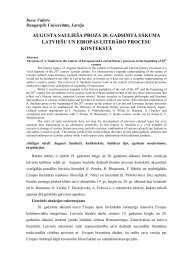
Andrejs Bulanovs<br />
Daugavpils University, Latvia<br />
PRINCIPLES OF RECORDING IMAGE-MATRIX<br />
HOLOGRAPHIC STEREOGRAM<br />
Abstract<br />
A method for producing <strong>holographic</strong> <strong>stereogram</strong>s by <strong>image</strong>-<strong>matrix</strong> <strong>recording</strong> technology with reduced<br />
geometrical constraints is presented. The type <strong>of</strong> <strong>holographic</strong> <strong>stereogram</strong> produced can <strong>of</strong>fer a combination <strong>of</strong><br />
large viewing zone, arbitrary viewing distance, minimal <strong>image</strong> distortion, and high spatial resolution, depending<br />
on alterable parameters in the <strong>image</strong> processing s<strong>of</strong>tware. The techniques described are applicable to one step<br />
<strong>recording</strong> <strong>stereogram</strong>s with horizontal parallax. Because <strong>of</strong> the difficulty <strong>of</strong> <strong>recording</strong> a full two-dimensional<br />
array <strong>of</strong> parallax <strong>image</strong>s, the <strong>holographic</strong> <strong>stereogram</strong>s are horizontal parallax only, using a linear series <strong>of</strong> view<br />
to present horizontal parallax while eliminating less-useful vertical parallax. For producing 3D effect<br />
<strong>holographic</strong> <strong>stereogram</strong>s present a series <strong>of</strong> discrete apertures to the viewer, each contains information from a<br />
single two-dimensional <strong>image</strong> <strong>of</strong> an object.<br />
Keywords: <strong>holographic</strong> <strong>stereogram</strong>, <strong>image</strong>-<strong>matrix</strong> holography, stereo vision<br />
Introduction<br />
Recently, dot-<strong>matrix</strong> and <strong>image</strong>-<strong>matrix</strong> holograms based on diffraction gratings have<br />
become widely used as anti-counterfeiting devices<br />
documents against<br />
where they are employed to protect<br />
forgery [1-4]. Such protective holograms cannot be reproduced by<br />
conventional colour scanning or printing technique and therefore find a wide range <strong>of</strong><br />
applications in document security field. In order to increase protection efficiency, holograms<br />
are rapidly integrated with other protective elements one <strong>of</strong> which is a <strong>stereogram</strong>.<br />
digital <strong>holographic</strong> <strong>stereogram</strong> is one <strong>of</strong> the highest quality methods for displaying threedimensional<br />
objects with help <strong>of</strong> computer-generated synthetic <strong>image</strong>s. Holographic<br />
<strong>stereogram</strong>s present a series <strong>of</strong> discrete viewpoints (apertures) to the viewer, each contain<br />
information from a single two-dimensional <strong>image</strong> <strong>of</strong> a scene. Instead <strong>of</strong> <strong>recording</strong> a threedimensional<br />
‘real’ object a sequence <strong>of</strong> flat two-dimensional <strong>image</strong>s <strong>of</strong> an object are recorded.<br />
Each <strong>image</strong> is a single view from a sequence <strong>of</strong> ‘parallax <strong>image</strong>s’ and all <strong>of</strong> them are recorded<br />
together in the sets <strong>of</strong> complex pixels on the master hologram. One complex pixel contains<br />
diffraction pattern for reconstruction <strong>of</strong> one graphical dot <strong>of</strong> all initial parallax <strong>image</strong>s in to<br />
the corresponding viewing zones. The '<strong>image</strong>-<strong>matrix</strong>' technology for optical <strong>recording</strong> <strong>of</strong><br />
protective holograms is currently dominate in applied holography [5]. This technology can be<br />
considered as laser beam interference lithography and allows fast and large area periodical<br />
structures to be patterned with relative simple equipment. The interference lithography<br />
principle is based on the interference <strong>of</strong> two or more coherent lights to form a horizontal<br />
standing wave for grating pattern which can be recorded on the photoresist. This paper<br />
presents the theoretical and experimental results to create <strong>holographic</strong> <strong>stereogram</strong>s using<br />
“<strong>image</strong>-<strong>matrix</strong>” <strong>recording</strong> technology.<br />
The
Theoretical background<br />
The principle <strong>of</strong> dot-<strong>matrix</strong> holography is based on decomposition <strong>of</strong> a hologram <strong>image</strong><br />
into a two-dimensional array <strong>of</strong> elementary pixels containing diffraction gratings with<br />
parameters that need mathematical calculation. Their size usually lies in the range <strong>of</strong> 10-100<br />
m and depends on the technology <strong>of</strong> optical <strong>recording</strong> that is used. In each elementary pixel<br />
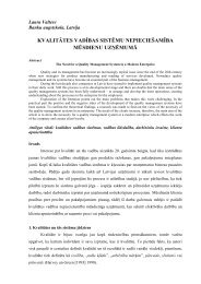
<strong>of</strong> the hologram there is a diffraction grating with certain period d and orientation angle <br />
relative to horizontal axis in the plane <strong>of</strong> hologram (Fig. 1a). Size and shape <strong>of</strong> pixels may<br />
also change.<br />
The calculation task is to define the condition that a particular pixel <strong>of</strong> a hologram would<br />
direct a given spectral part <strong>of</strong> diffracted light towards the observer. The observer can see<br />
diffracted light from each element <strong>of</strong> a hologram only at a certain angle; and the total<br />
perception <strong>of</strong> diffraction <strong>of</strong> all elements makes a visual effect that corresponds to the initial<br />
graphic design. It is obvious that the main factors for reconstruction <strong>of</strong> the whole hologram<br />
are orientation and period <strong>of</strong> diffraction grating in each pixel, as well as position <strong>of</strong> an<br />
observer and the light source during the reconstruction. In these conditions, the <strong>holographic</strong><br />
<strong>image</strong> will correspond to the initial graphic design. If the positions <strong>of</strong> an observer and the<br />
light source are defined, period d and orientation angle ϕ (Fig. 1b) <strong>of</strong> the grating completely<br />
determine the conditions when an incident white light can be diffracted with the given<br />
spectral region towards the observer. In this case, the color <strong>of</strong> the hologram element<br />
corresponds to the color <strong>of</strong> a dot in the initial graphic <strong>image</strong>.<br />
Y<br />
Incident light<br />
Y<br />
k r 1<br />
d<br />
y<br />
Pixel<br />
x<br />
X<br />
z<br />
Diffracted light<br />
k r 2<br />
d y<br />
ϕ<br />
X<br />
d x<br />
Fig. 1. a) Parameters <strong>of</strong> diffraction grating. b) An <strong>image</strong> element formation by diffraction pixel.<br />
The coordinate system XYZ is chosen in such a way that the hologram is lying in the<br />
plane XY, and the Z axis directed to the observer from the center <strong>of</strong> the hologram (Fig. 1b).<br />
Assume that the observer's eye is on the Z axis at the distance <strong>of</strong> about 30 cm. The light<br />
source illuminating the hologram has a continuous spectrum in the visible region, and the
direction <strong>of</strong> the incident radiation is given by the unit vector k r 1 . We must define the<br />
parameters (d, φ) <strong>of</strong> the diffractive pixel with the coordinates (x, y) , which the observer can<br />
see in the color with the wavelength λ 0 . If the light with the wavelength λ falls on a flat<br />
diffraction grating along the unit vector k r<br />
1 = (cosα 1,<br />
cosβ1,<br />
cos γ1)<br />
the direction <strong>of</strong><br />
diffraction, which is defined by the unit vector k r<br />
2 = (cosα 2 , cos β2<br />
, cos γ2<br />
) , can be determined<br />
by the formulas [6]:<br />
cos α ±<br />
λ<br />
2 = cos α1<br />
;<br />
dx<br />
cos β ±<br />
λ<br />
2 = cosβ1<br />
d<br />
; 2<br />
2<br />
cos γ2 1 - cos α2<br />
− cos β<br />
y<br />
2<br />
= . (1)<br />
We take the position <strong>of</strong> a point source with continuous spectrum <strong>of</strong> light in the plane YZ. If<br />
the angle between the Z axis and direction from the light source to the hologram center is θ ,<br />
then k r<br />
= (0, sin θ,cos θ) , where the change <strong>of</strong> the Z-component <strong>of</strong> incident light after<br />
1 −<br />
reflection from the hologram surface is taken into account. The direction <strong>of</strong> the +1 diffraction<br />
order from the pixel with the coordinates (x, y) to the eye <strong>of</strong> the observer is defined by the ort<br />
x<br />
2 = (- L<br />
y<br />
L<br />
z<br />
L<br />
vector kr 2 2 2<br />
,- , ) , where L = x + y + z is the distance between the pixel and the eye <strong>of</strong><br />
the observer. Taking into account the above mentioned conditions, the formulas in (1) will<br />
look like the following:<br />
λ sin φ<br />
cos α2 = − ;<br />
d<br />
λ cos φ<br />
2<br />
2<br />
cos β 2 = −sin θ + ; cos γ2 = 1 - cos α2<br />
− cos β2<br />
(2)<br />
d<br />
For the central pixel <strong>of</strong> the hologram with coordinates (0, 0) and the color λ 0 based on the<br />
formulas in (2), we obtain the following parameters <strong>of</strong> the diffraction grating:<br />
λ0<br />
(d, φ) = (d0 , 0) = ( , 0) , where<br />
sin θ<br />
λ<br />
0 = .<br />
sin θ<br />
d<br />
0<br />
At the next step, we can define the parameters (d, φ) <strong>of</strong> a pixel with the coordinates (x, y)<br />
having the same visual characteristics (color, brightness) for the observer as in the case <strong>of</strong> the<br />
central pixel. This requires solving a system <strong>of</strong> equations for the variables d and φ :<br />
λ0<br />
sin φ<br />
cos α2 = − ;<br />
d<br />
λ0<br />
cos φ<br />
cos β2 = −sin θ + ;<br />
d<br />
x<br />
cos α 2 = - ;<br />
L<br />
y<br />
cos β 2 = - . (3)<br />
L<br />
From the equations in (3) we can find the formulas for calculating the parameters <strong>of</strong><br />
diffraction gratings <strong>of</strong> the pixel:<br />
cos α2<br />
tg φ = -<br />
⇒<br />
cos β + sin θ<br />
2<br />
⎧ x ⎫<br />
φ(x, y) = arctg⎨<br />
⎬<br />
(4)<br />
⎩L sin θ - y ⎭<br />
λ<br />
sin φ<br />
0<br />
d = -<br />
⇒<br />
cos α2<br />
d0<br />
L sin θ<br />
d(x, y) =<br />
(5)<br />
2 2<br />
(L sin θ - y) + x
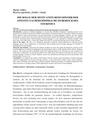
Calculation <strong>of</strong> pixel parameters for <strong>stereogram</strong>s performs according to formulas (4,5) It is<br />
only necessary to take into account a position <strong>of</strong> observation for each parallax <strong>image</strong> <strong>of</strong> the<br />
hologram that can be achieved by replacing the old variables (x, y) in formulas (4,5) by the<br />
new ones(x − x<br />
i<br />
, y − y<br />
i<br />
) , where (x<br />
i<br />
, y<br />
i<br />
) indicate the positions <strong>of</strong> viewing zones in the<br />
observation plane (Fig.2).<br />
1 2 3 4 5 6 7 8 9<br />
Fig.2 Reconstruction from <strong>holographic</strong> <strong>stereogram</strong> the set <strong>of</strong> parallax <strong>image</strong>s into<br />
successive zones <strong>of</strong> viewing (apertures).<br />
Results and discussion.<br />
The most important thing which helps us to see the world in three-dimensions is the<br />
phenomenon <strong>of</strong> parallax. When you look at an object, you see only the front side. When you<br />
move your head to one side you see the front and another side <strong>of</strong> the object. This is also very<br />
important in holography and constitutes the most common difference between photography<br />
and holography. When you are look at a hologram, you can see the <strong>image</strong> in different visual<br />
angles when you move your head to the side just as and when you are looking at a real object.<br />
This phenomenon is called parallax. During the reconstruction <strong>of</strong> a hologram with horizontal<br />
parallax, the observer sees the <strong>image</strong> <strong>of</strong> the object in two different perspectives. When we<br />
look at a real object, we also see the object in two different perspectives, because there is a<br />
space between our eyes. The basic principle <strong>of</strong> <strong>stereogram</strong> formation lays in the combination<br />
<strong>of</strong> several photographs <strong>of</strong> an object from different angles in to one hologram. Each <strong>of</strong> these<br />
pictures are then to be recorded onto a little areas <strong>of</strong> the <strong>holographic</strong> film plate and can be<br />
recovered with help <strong>of</strong> illumination into the different viewing zones.<br />
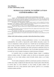
For <strong>recording</strong> a diffraction grating with certain size, period and the orientation angle the<br />
<strong>image</strong>-<strong>matrix</strong> optical set-up shown in Fig. 3 was used. It utilizes a diode laser (100 mW, 405<br />
nm), whose cleared and expanded beam illuminates a transparent SVGA (800x600 pixels)<br />
spatial light modulator (SLM) located behind Fourier lens.
a)<br />
2<br />
3<br />
4<br />
5<br />
6<br />
7<br />
b)<br />
1<br />
1-Laser<br />
2-Optical filter<br />
4-SLM<br />
6-Focusing lens<br />
3-Fourier lens<br />
5-Fourier filter<br />
7- XY stage<br />
Fig. 3 a) Optical scheme <strong>of</strong> <strong>recording</strong> device.<br />
b) Structure <strong>of</strong> <strong>image</strong>-<strong>matrix</strong> hologram.<br />
A spatial filter is positioned in the Fourier plane behind the SLM to block a zero order and<br />
the orders higher than both first orders. After the inverse Fourier transformation, a hologram<br />
is created with the help <strong>of</strong> a micro objective by interference <strong>of</strong> the I +1 and I- 1 orders <strong>of</strong> the<br />
wave diffracted at the modulator. An <strong>image</strong> is displayed on the SLM is reduced to a<br />
microscopic size by a lens system and recorded in a photoresist plate placed on a XY-stage.<br />
Each separate <strong>matrix</strong> <strong>image</strong> displayed on the SLM contains a set <strong>of</strong> gratings with a grating<br />
pitch and orientation adjusted to the requirements.<br />
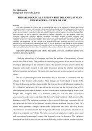
a) b)<br />
Fig. 4. a) Electron microscope <strong>image</strong> <strong>of</strong> <strong>stereogram</strong> complex pixel consisting from nine<br />
sub pixels corresponding to the different parallax <strong>image</strong>s. b) Electron microscope <strong>image</strong><br />
<strong>of</strong> one frame <strong>of</strong> <strong>holographic</strong> <strong>stereogram</strong>.<br />
The figure Fig. 4a shows us the method how the pixels <strong>of</strong> nine parallax pictures are<br />
multiplexed into one complex pixel <strong>of</strong> <strong>stereogram</strong>. Fig. 4b shows a SEM <strong>image</strong> <strong>of</strong> one frame<br />
<strong>of</strong> the <strong>stereogram</strong> containing 9 combined <strong>image</strong>s for creating an illusion <strong>of</strong> a 3D object. In<br />
this case, each frame consists <strong>of</strong> an array <strong>of</strong> 8x6 pixels <strong>of</strong> size 15 µm. Every pixel in the array<br />
corresponds to a graphic point in one <strong>of</strong> the combined <strong>image</strong>s. Each <strong>of</strong> the combined <strong>image</strong>s<br />
is visible from a certain angle that is determined by the orientation <strong>of</strong> diffraction grating <strong>of</strong><br />
pixels, appropriate to this <strong>image</strong>. The size <strong>of</strong> a pixel is proportional to a level <strong>of</strong> grey color <strong>of</strong><br />
the appropriate graphic point. The Fig. 5 shows the results <strong>of</strong> the <strong>recording</strong> a <strong>holographic</strong><br />
<strong>stereogram</strong> by the described method.
Fig.5 Photo <strong>of</strong> <strong>image</strong>s recovered from <strong>holographic</strong> <strong>stereogram</strong> and received<br />
from different viewing zones.<br />
Conclusion<br />
The proposed method allows for calculation and integration <strong>of</strong> a <strong>holographic</strong> <strong>stereogram</strong><br />
elements into the structure <strong>of</strong> an <strong>image</strong>-<strong>matrix</strong> hologram with help <strong>of</strong> self made computer<br />
programs. This method <strong>of</strong> <strong>recording</strong> <strong>stereogram</strong> can be considered as alternative to the<br />
existing methods in terms <strong>of</strong> competitive efficiency. The presented technology has been tested<br />
and can be readily used as an additional degree <strong>of</strong> protection in the production <strong>of</strong> '<strong>image</strong><strong>matrix</strong>'<br />
holograms.<br />
Acknowledgments<br />
This research was partly supported by the ESF project “Starpdisciplinārās zinātniskās grupas<br />
izveidošana jaunu fluorescentu materiālu un metožu izstrādei un ieviešanai” Nr.<br />
2009/0205/1DP/1.1.1.2.0/09/APIA/VIAA/152<br />
Bibliography<br />
[1] A.Bulanovs, V.Gerbreders, V.Paschkevich, J.Teteris. (2006) Dot-<strong>matrix</strong> <strong>holographic</strong><br />
<strong>recording</strong> in amorphous chalcogenide films, Proc. <strong>of</strong> SPIE Vol.6596, 128-131<br />
[2] A.Bulanovs, V.Gerbreders, V.Paschkevich. (2007) Digital dot-<strong>matrix</strong> device for<br />
<strong>holographic</strong> <strong>recording</strong>, Latvijas Fizikas un Tehnisko Zinātņu Žurnals, Nr 5-2007, 32-38.<br />
[3] A.Bulanovs, Vj. Gerbreders, V. Pashkevich. (2008) Principles <strong>of</strong> creation and<br />
reconstruction <strong>of</strong> dot-<strong>matrix</strong> holograms. Latvijas Fizikas un Tehnisko Zinātņu Žurnals, Nr<br />
2-2008, 44-51.<br />
[4] C.-K.Lee, J.W.-J.Wu, S.-L.Yeh, C.-W.Tu, (2000) Optical configuration and colorrepresentation<br />
range <strong>of</strong> a variable pitch dot <strong>matrix</strong> <strong>holographic</strong> printer. Appl. Optics,<br />
Vol.39, No.1, 40.<br />
[5] Pizzanelly D. (2004) The development <strong>of</strong> direct-write digital holography.Technical review,<br />
Holographer.org.<br />
[6] Yaotang.L, Tianji W., Shining Y., Shining Y., Shichao Z. (1998) Theoretical and<br />
experimental study <strong>of</strong> dot <strong>matrix</strong> hologram, Proc. SPIE Vol. 3569, 121.