P12 Fully Sealed Container Cermet Potentiometers Military and ...
P12 Fully Sealed Container Cermet Potentiometers Military and ...
P12 Fully Sealed Container Cermet Potentiometers Military and ...

You also want an ePaper? Increase the reach of your titles
YUMPU automatically turns print PDFs into web optimized ePapers that Google loves.
<strong>P12</strong><br />
Vishay Sfernice<br />
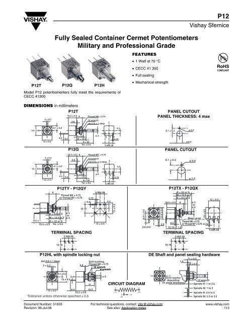
<strong>Fully</strong> <strong>Sealed</strong> <strong>Container</strong> <strong>Cermet</strong> <strong>Potentiometers</strong><br />
<strong>Military</strong> <strong>and</strong> Professional Grade<br />
<strong>P12</strong>T <strong>P12</strong>Q <strong>P12</strong>H<br />
Model <strong>P12</strong> potentiomenters fully meet the requirements of<br />
CECC 41300<br />
FEATURES<br />
• 1 Watt at 70 °C<br />
• CECC 41 300<br />
• Full sealing<br />
• Mechanical strength<br />
RoHS<br />
COMPLIANT<br />
DIMENSIONS in millimeters<br />
<strong>P12</strong>T<br />
2 ± 0.2<br />
10.2 ± 0.5 8<br />
0.8<br />
Thread M6 × 0.75<br />
10 wrench<br />
slot 0.6 × 1 deep<br />
PANEL CUTOUT<br />
PANEL THICKNESS: 4 max<br />
12 ± 0.5<br />
6.1 ± 0.2<br />
4.3<br />
6.1 ± 0.2 ø 2.2<br />
12 ± 0.5<br />
0.4 6.5<br />
<strong>P12</strong>Q<br />
K = 9.5<br />
M = 12.5<br />
R = 22<br />
Tol. ± 0.5<br />
ø 3<br />
a b c<br />
0.75<br />
5.08 5.08<br />
ø 6.5<br />
PANEL CUTOUT<br />
2 ± 0.2<br />
10.2 ± 0.5 8<br />
0.8<br />
Thread M7 × 0.75<br />
10 wrench<br />
slot 0.8 × 1.4 deep<br />
6.1 ± 0.2 ø 2.2<br />
12 ± 0.5<br />
6.1 ± 0.2<br />
4.3<br />
12 ± 0.5<br />
8<br />
0.4 6.5<br />
Thread M6 × 0.75<br />
or Thread M7 × 0.75<br />
E = 9.5<br />
F = 12.5<br />
G = 22<br />
Tol. ± 0.5<br />
<strong>P12</strong>TY - <strong>P12</strong>QY<br />
10.16<br />
K = 9.5 or E ø 3<br />
or<br />
M = 12.5 or F ø 4<br />
6.5 ± 1 R = 22 or G<br />
10.4 ± 0.5 Tol. ± 0.5<br />
12 ± 0.5<br />
0.4<br />
0.75<br />
TERMINAL SPACING<br />
5.085.08<br />
ø 4<br />
5.08 5.08<br />
a b c<br />
0.75<br />
5.08 5.08<br />
4.3<br />
12<br />
± 0. 5<br />
6.9<br />
± 0. 5<br />
3.8 min<br />
1 2.9 ± 0. 5<br />
0.9<br />
ø 7.5<br />
<strong>P12</strong>TX - <strong>P12</strong>QX<br />
R = 22 or G<br />
M = 12.5 or F<br />
K = 9.5 or E<br />
10.5 ± 0.5 8 ø 3<br />
or<br />
ø 4<br />
Base Level<br />
Thread M6 × 0.75<br />
a b c<br />
0.5 or Thread M7 × 0.75 0.75<br />
10.16 1.25<br />
5.085.08<br />
TERMINAL SPACING<br />
5.085.08<br />
12<br />
± 0. 5<br />
12 ± 0.5<br />
10.16<br />
a b c<br />
10.16<br />
c b a<br />
<strong>P12</strong>HL with spindle locking nut<br />
slot 0.6 x 1 deep<br />
2 ± 0.2<br />
0.8<br />
Split bushing<br />
Thread M6 × 0.75<br />
10 wrench<br />
8 wrench<br />
6.1 ± 0.2<br />
0.4<br />
ø 3<br />
12 ± 0.5<br />
11<br />
12 ± 0.5<br />
6.5<br />
12.5<br />
10.2 ± 0.5<br />
Tolerance unless otherwise specified ± 0.5<br />
CIRCUIT DIAGRAM<br />
a<br />
c<br />
(1)<br />
(3)<br />
b cw<br />
(2)<br />
DE Shaft <strong>and</strong> panel sealing hardware<br />
1.5<br />
Shim washer<br />
depending<br />
on panel thickness<br />
11 ± 0.5<br />
9 ± 0.1<br />
12 wrench<br />
Spindle R: 1 to 3.5<br />
Spindle M: 1 to 2<br />
Spindle R: 2.5 to 5<br />
Spindle M: 2.5 to 3.5<br />
Document Number: 51033 For technical questions, contact: sfer@vishay.com www.vishay.com<br />
Revision: 06-Jul-06 See also: Application notes 113
<strong>P12</strong><br />
Vishay Sfernice<br />
<strong>Fully</strong> <strong>Sealed</strong> <strong>Container</strong> <strong>Cermet</strong> <strong>Potentiometers</strong><br />
<strong>Military</strong> <strong>and</strong> Professional Grade<br />
ELECTRICAL SPECIFICATIONS<br />
Resistive Element<br />
cermet<br />
Electrical Travel 270° ± 10°<br />
Resistance Range Linear Law 22 Ω to 10 MΩ<br />
Logarithmic Laws<br />
100 Ω to 2.2 MΩ<br />
St<strong>and</strong>ard series E3 1 - 2.2 - 4.7 <strong>and</strong> on request 1 - 2 - 5<br />
Tolerance St<strong>and</strong>ard ± 20 %<br />
On Request ± 10 %<br />
Power Rating Linear 1 W at + 70 °C<br />
Logarithmic 0.5 W at + 70 °C<br />
Temperature Coefficient<br />
See St<strong>and</strong>ard Resistance Element Data<br />
Limiting Element Voltage (Linear Law)<br />
350 V<br />
Contact Resistance Variation<br />
3 % or 3 Ω<br />
End Resistance (Typical)<br />
1 Ω<br />
Dielectric Strength (RMS)<br />
2000 V<br />
Insulation Resistance (500 VDC)<br />
10 6 MΩ<br />
MECHANICAL SPECIFICATIONS<br />
Mechanical Travel 300° ± 5°<br />
Operating Torque (max. Ncm) 2 typical<br />
End Stop Torque (max. Ncm) style H: 15 - T.Q.: 35<br />
Tightening Torque (max. Ncm) 150<br />
Unit Weight (max. g) 7.6 to 10<br />
ENVIRONMENTAL SPECIFICATIONS<br />
Temperature Range - 55 °C to + 125 °C<br />
Climatic Category 55/100/56<br />
Sealing<br />
fully sealed<br />
container IP67<br />
POWER RATING CHART<br />
POWER IN WATT<br />
LIN. LAW “A”<br />
1<br />
LOG. LAWS “L & F”<br />
0.5<br />
0<br />
0 20 40 60 70 80 100 125 140<br />
AMBIENT TEMPERATURE IN DEGREES CELSIUS<br />
RESISTANCE LAWS<br />
100<br />
80<br />
F<br />
% TOTAL RESISTANCE<br />
60<br />
40<br />
20<br />
A<br />
L<br />
0<br />
0 20 40<br />
60<br />
80 100<br />
% CLOCKWISE SHAFT ROTATION<br />
www.vishay.com For technical questions, contact: sfer@vishay.com Document Number: 51033<br />
114 See also: Application notes Revision: 06-Jul-06
<strong>Fully</strong> <strong>Sealed</strong> <strong>Container</strong> <strong>Cermet</strong> <strong>Potentiometers</strong><br />
<strong>Military</strong> <strong>and</strong> Professional Grade<br />
<strong>P12</strong><br />
Vishay Sfernice<br />
PERFORMANCE<br />
TESTS<br />
Load Life<br />
Climatic Sequence<br />
Long Term Damp Heat<br />
Rapid Temperature Change<br />
Shock<br />
Vibration<br />
Rotational Life<br />
CONDITIONS<br />
1000 hours at rated power<br />
90’/30’ - ambient temp. 70 °C<br />
Phase A dry heat 125 °C<br />
Phase B damp heat<br />
Phase C cold - 55 °C<br />
Phase D damp heat 5 cycles<br />
56 days<br />
40 °C 93 % RH<br />
5 cycles<br />
- 55 °C at + 125 °C<br />
50 g at 11 ms<br />
3 successive shocks<br />
in 3 directions<br />
10 - 55 Hz<br />
0.75 mm or 10 g<br />
during 6 hours<br />
25 000 cycles<br />
TYPICAL VALUES AND DRIFTS<br />
ΔRT<br />
RT (%) ΔR1-2<br />
R1-2 (%)<br />
± 1 %<br />
Contact res. variation: < 3 % Rn<br />
± 0.5 % ± 1 %<br />
± 0.5 % ± 1 %<br />
Dielectric strength: 1000 V RMS<br />
Insulation resistance: > 10 4 MΩ<br />
± 0.5 %<br />
± 0.1 % ± 0.2 %<br />
± 0.1 %<br />
± 3 %<br />
Contact res. variation: < 2 % Rn<br />
ΔV1-2<br />
V1-3<br />
≤ ± 0.2 %<br />
STANDARD RESISTANCE ELEMENT DATA<br />
STAN-<br />
DARD<br />
RESIS-<br />
TANCE<br />
VALUES<br />
MAX.<br />
POWER<br />
AT 70 °C<br />
LINEAR LAW<br />
MAX.<br />
WORKING<br />
VOLTAGE<br />
MAX.<br />
WIPER<br />
CUR.<br />
MAX.<br />
POWER<br />
AT 70 °C<br />
LOGS LAW<br />
MAX.<br />
WORKING<br />
VOLTAGE<br />
MAX.<br />
WIPER<br />
CUR.<br />
TCR<br />
- 55 °C<br />
+ 125 °C<br />
Ω W V mA W V mA ppm/°C<br />
22<br />
47<br />
1 4.69<br />
6.85<br />
213.2<br />
145.8<br />
0<br />
+ 200<br />
100<br />
220<br />
470<br />
1K<br />
2.2K<br />
4.7K<br />
10K<br />
10<br />
14.8<br />
21.6<br />
31.6<br />
46.9<br />
63.5<br />
100<br />
100<br />
67.4<br />
46.1<br />
31.6<br />
21.3<br />
14.5<br />
10<br />
0.5 22.4<br />
33.2<br />
48.5<br />
79.7<br />
22.4<br />
15.1<br />
10.3<br />
7.07<br />
22K<br />
148.3 6.7<br />
105 4.77<br />
47K<br />
216.7 4.6<br />
153 3.26<br />
± 100<br />
100K<br />
220K<br />
470K<br />
1M<br />
2.2M<br />
4.7M<br />
10M<br />
1<br />
0.56<br />
0.26<br />
0.12<br />
0.05<br />
0.02<br />
0.01<br />
316.2<br />
350<br />
350<br />
350<br />
350<br />
350<br />
350<br />
3.16<br />
1.59<br />
0.75<br />
0.35<br />
0.16<br />
0.07<br />
0.01<br />
0.5<br />
0.26<br />
0.12<br />
0.05<br />
224<br />
332<br />
350<br />
350<br />
350<br />
2.24<br />
1.51<br />
0.74<br />
0.35<br />
0.16<br />
MARKING<br />
Printed:<br />
- VISHAY trademark<br />
- series<br />
- ohmic value (in Ω )<br />
- tolerance (in %)<br />
- manufacturing date<br />
- marking of terminals 1 or a<br />
SPECIAL FEATURES<br />
SHAFTS<br />
Lengths are measured from the mounting surface to the free<br />
end of shaft. Shaft slot is aligned with the wiper within ± 10°.<br />
Special shafts are available, in accordance with drawings<br />
supplied by customers. We recommend customers not to<br />
machine shafts, in order to avoid damage. Bending or torsion<br />
of terminal should be avoided.<br />
SHAFT AND PANEL SEALING HARDWARE<br />
The type <strong>P12</strong>T with R or M shaft can be provided with an<br />
optional “DE” sealing hardware which ensures sealing of<br />
both the shaft <strong>and</strong> the mounting panel. “DE” sealing<br />
hardware can be supplied in a separate envelope.<br />
SHAFT LOCKING<br />
- The shaft locking bushing is available only with <strong>P12</strong>H<br />
potentiometers. Torque applied to locking nuts should not<br />
exceed 15 Ncm.<br />
Document Number: 51033 For technical questions, contact: sfer@vishay.com www.vishay.com<br />
Revision: 06-Jul-06 See also: Application notes 115
<strong>P12</strong><br />
Vishay Sfernice<br />
<strong>Fully</strong> <strong>Sealed</strong> <strong>Container</strong> <strong>Cermet</strong> <strong>Potentiometers</strong><br />
<strong>Military</strong> <strong>and</strong> Professional Grade<br />
ORDERING INFORMATION<br />
<strong>P12</strong> OR <strong>P12</strong>H T M 470 kΩ 20 % A DE BO<br />
SERIES OR<br />
SHAFT LOCKING<br />
STYLE SHAFT OHMIC VALUE TOLERANCE RESISTANCE<br />
LAW<br />
PANEL SEALING<br />
DEVICE<br />
PACKAGING<br />
SAP PART NUMBERING GUIDELINES<br />
P 1 2 T A B S 4 7 4 M A B 2 D E<br />
MODEL BUSHING SHAFT LEADS OHMIC TOL LAW PACKAGING SPECIAL<br />
VALUE<br />
(IF APPLICABLE)<br />
See the end of this data book for conversion tables<br />
www.vishay.com For technical questions, contact: sfer@vishay.com Document Number: 51033<br />
116 See also: Application notes Revision: 06-Jul-06
Notice<br />
Legal Disclaimer Notice<br />
Vishay<br />
Specifications of the products displayed herein are subject to change without notice. Vishay Intertechnology, Inc.,<br />
or anyone on its behalf, assumes no responsibility or liability for any errors or inaccuracies.<br />
Information contained herein is intended to provide a product description only. No license, express or implied, by<br />
estoppel or otherwise, to any intellectual property rights is granted by this document. Except as provided in Vishay's<br />
terms <strong>and</strong> conditions of sale for such products, Vishay assumes no liability whatsoever, <strong>and</strong> disclaims any express<br />
or implied warranty, relating to sale <strong>and</strong>/or use of Vishay products including liability or warranties relating to fitness<br />
for a particular purpose, merchantability, or infringement of any patent, copyright, or other intellectual property right.<br />
The products shown herein are not designed for use in medical, life-saving, or life-sustaining applications.<br />
Customers using or selling these products for use in such applications do so at their own risk <strong>and</strong> agree to fully<br />
indemnify Vishay for any damages resulting from such improper use or sale.<br />
Document Number: 91000<br />
www.vishay.com<br />
Revision: 08-Apr-05 1