Issue No. 1, 2000 - Ductile Iron Society
Issue No. 1, 2000 - Ductile Iron Society
Issue No. 1, 2000 - Ductile Iron Society

Create successful ePaper yourself
Turn your PDF publications into a flip-book with our unique Google optimized e-Paper software.
To Promote the production and application of ductile iron castings <strong>Issue</strong> 1, <strong>2000</strong><br />
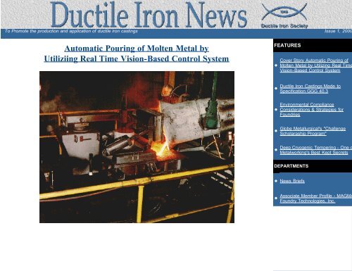
Automatic Pouring of Molten Metal by<br />
Utiliziing Real Time Vision-Based Control System<br />
FEATURES<br />
Cover Story Automatic Pouring of<br />
• Molten Metal by Utilizing Real Time<br />
Vision-Based Control System<br />
<strong>Ductile</strong> <strong>Iron</strong> Castings Made to<br />
• Specification GGG 40.3<br />
Environmental Compliance<br />
• Considerations & Strategies for<br />
Foundries<br />
Globe Metallurgical's "Challenge<br />
• Scholaraship Program"<br />
Deep Cryogenic Tempering - One o<br />
• Metalworking's Best Kept Secrets<br />
DEPARTMENTS<br />
• News Briefs<br />
Associate Member Profile - MAGMA<br />
• Foundry Technologies, Inc.<br />
•<br />
•<br />
•
Automatic Pouring<br />
Automatic Pouring of Molten Metal by Utilizing<br />
Real Time Vision Based Control System<br />
by; E. Tabatabaei, Inductotherm Corporation; Rancocas, New Jersey<br />
ABSTRACT<br />
A closed-loop automatic molten metal dispensing system based on vision technology is presented. Vision technology and its<br />
effects on industrial automation and reasons for selecting vision sensor as opposed to other sensing devices such as X-ray and<br />
laser is discussed.<br />
The control is self-compensating and utilizes automatic learning schemes to repeatedly and accurately fill the molds.<br />
The level in the sprue cup is sensed by a vision camera and compared to a predetermined level profile. The difference is then<br />
used to drive a servo-driven actuator. The control calculates the flow of molten metal into the mold to learn the gating system<br />
characteristics. This information is used to improve the future pours, which may be affected by the change in the orifice diameter<br />
and the level of molten metal in the tundish.<br />
In case of a flaskless mold line, the pour tundish is automatically positioned over the sprue cup.<br />
The system has been successfully tested both in the laboratory and on the production lilne.<br />
The rising cost of material and labor has forced today's foundries to automate the various aspects of their operation to increase<br />
efficiency and productivity. The extent of this automation has also reached the casting process. The modern delivery systems and<br />
high speed molding machines have necessitated the need for an automatic pouring system to produce high-quality castings as a<br />
high throughput, while eliminating costly overpours.<br />
This paper will discuss a closed-loop automatic pouring system based on Vision Technology for non-contact measurement of the<br />
molten metal level in the sprue cup.<br />
After a brief discussion of the vision sensing, the control scheme will be introduced.<br />
VISION SENSING<br />
A typical vision system is comprised of a camera, lens, and image-processing electronics. The object is viewed by the camera and<br />
a live picture is sent to the image-processing electronics at a rate of 30 frames or samples per second. Each point of the picture is<br />
converted to an element called the pixel with a value representing the brightness of the original picture. The collection of the pixels<br />
form an image, which can be processed by a computer for feature extraction (Fig. 1).<br />
Figure 1. A typical vision system.<br />
file:///C|/WEBSHARE/062013/magazine/<strong>2000</strong>_1/automatic.htm[6/19/2013 8:02:57 AM]
Automatic Pouring<br />
Level Measurement<br />
To measure the level of the molten metal in the sprue cup, it is essential to distinguish between the molten metal and the sprue<br />
cup. This is accomplished by optical filters and electronic thresholding of the image.<br />
The brightness of the molten metal provides an excellent contract between the sand mold and the metal in the sprue cup, and,<br />
therefore, a crisp image of the molten metal represented by white pixels can be obtained without utilizing any special lighting.<br />
Since the camera looks at a large area and not only one point of the sprue cup, it is necessary to reach the area of the sprue cup<br />
or the region of interest (Fig. 2a). The region of interest has two functions, it is used in metal level calculation (Fig. 2b) and in the<br />
elimination of the stream contribution in the total image area. By looking directly at the sprue cup and electronically blocking the<br />
stream, the need for special sprue cup design is eliminated (Figs. 2c and 2d).<br />
Fig. 2. Sprue cup area (region of interest).<br />
The molten metal level is calculated by counting complete lines of white pixel, filtering the stream out, and normalizing the total<br />
count to the cup area.<br />
Why Vision?<br />
The technological advancement of the past 10 years in the areas of computer and sensor technology has made a tremendous<br />
impact on automating industrial process control. The increased productivity, reliability, and safety is what this automation has<br />
offered.<br />
Vision systems, being a part of this advancement, are being widely used to automate industrial quality control, process control, and<br />
gauging, to name a few.<br />
The advantages of a vision system in the automatic pouring process are:<br />
Availability and relatively low cost of the components<br />
Safety<br />
Visual feedback<br />
The availability and low cost of the vision components, plus the fact that -- unlike other measuring devices such as X-ray and laser<br />
-- there is no need for any sort of radiation, makes this system attractive. Another feature is that, with the vision system, the<br />
process of positioning and pouring can be viewed live on a video monitor. The camera, in conjunction with a VCR, can provide a<br />
valuable tool to analyze the pouring process.<br />
VISIPOUR AUTOMATICE CONTROL SYSTEM<br />
The Visipour System consists of a power enclosure that houses the servo amplifier, power supplies, and line conditioner; a control<br />
station that contains the computer, vision electronics, servo controller, the input-output interface, control software, and a video<br />
monitor; two air-cooled camera housings; and a servo-driven stopper rod mechanism (Fig. 3).<br />
file:///C|/WEBSHARE/062013/magazine/<strong>2000</strong>_1/automatic.htm[6/19/2013 8:02:57 AM]
Automatic Pouring<br />
Figure 3. Vision system equipment.<br />
The operator interfaces with the system via a set of user-friendly menus through a front panel membrane keypad.<br />
The stopper rod mechanism is a servo-driven computer-controlled actuator, which provides fast response and accurate positioning<br />
of the stopper rod for quality pouring of molten metal. The quick response of a servo actuator, as opposed to a pneumatic one,<br />
which is slow in response for today's fast sampling sensors, is vital to automatic control of the stopper rod during opening, closing,<br />
and throttling.<br />
The servo closed-loop control system offers accurate positioning of the stopper rod and provides the means to automatically adjust<br />
the seating force of the rod into the nozzle.<br />
The vision system performs two functions: it automatically positions the tundish over the sprue cup, and it fills the mold according<br />
to its filling requirement.<br />
Tundish Tracking<br />
In the flaskless molding operation -- such as Disamatic line -- because of the change in the sand compactibility, the thickness of a<br />
given volume of green sand will vary from mold to mold. This variation in the mold thickness offsets the sprue cup in relation to<br />
the pouring nozzle, and, therefore, the pour stream will not fall in the center of the sprue cup. This causes splashing and sand<br />
erosion, and may increase the pour time.<br />
Another reason for the tracing is that the vision system requires the sprue cup (region of interest) to always be in the same<br />
position.<br />
The tracking is done by aligning the tundish over a mold and acquiring a picture of a notch formed on the side of the sand mold<br />
(Fig. 4). The ideal notch location to be used as a position reference is calculated by the vision system.<br />
The automatic positioning program will use this location to position the tundish by<br />
acquiring an image of the new mold's notch and comparing it to the ideal one. The<br />
system is moved according to the difference between the present notch location and<br />
the desired one.<br />
Automatic Pouring Control<br />
Fig. 4. A typical flaskless mold line. To produce quality castings, it is essential to fill the sand mold quickly and continuously,<br />
without interruption in the flow of the molten metal in the gating system. To assure this continuity, the sprue cup should be kept<br />
full during the pour to eliminate air entry into the gating system, which will result in unacceptable casting quality.<br />
The vision system is a closed-loop, computer-controlled, molten-metal-dispensing system designed to fill sand molds with varying<br />
metal intake characteristics at a high throughput.<br />
file:///C|/WEBSHARE/062013/magazine/<strong>2000</strong>_1/automatic.htm[6/19/2013 8:02:57 AM]
Automatic Pouring<br />
Due to the variation in the gating system, which determines the flow characteristic in the mold, the level of molten metal in the<br />
metal holding container, and the diameter of the orifice (which changes over time), the control system should be selfcompensating.<br />
To assure repeatability and accuracy of the pours over time, a powerful adaptive scheme is incorporated, which<br />
learns the characteristic of each pour and uses the acquired information to provide the controls with prior knowledge for the<br />
succeeding pours.<br />
The control system (Fig. 5) requires a tracking profile to use the guidance in controlling the level of molten metal in the sprue cup.<br />
This profile is based on the total time of pour and the desired levels of the molten metal in the sprue cup, during filling and at the<br />
end of the pour (Fig. 6).<br />
Figure 5. Vision system control loop.<br />
Figure 6. Level profile.<br />
The vision camera measures the level of molten metal in the sprue cup, which is directly proportional to the difference between the<br />
flow out of the orifice and the flow into the mold (Eq.1). This information is then used to predict the future level in the sprue cup<br />
(Eq. 2) due to metal in transition and also to calculate the mold intake (Eq. 3).<br />
(1)<br />
(2)<br />
(3)<br />
It takes a certain amount of time for the molten metal released from the orifice to reach the sprue cup (metal in transition). This<br />
time delay is directly related to the distance between the orifice and the sprue cup and must be accounted for in the control<br />
scheme.<br />
The comparison of predicted level to desired level, in conjunction with the estimated mold intake (Eq. 4), produces a process error<br />
(Eq. 5). The error is then fed to a proportional control (Eq. 6) to drive the servo actuator to correct the level of the molten metal in<br />
the sprue cup and eliminate the error.<br />
(4) (t) = g [F(t) ]<br />
(5)<br />
file:///C|/WEBSHARE/062013/magazine/<strong>2000</strong>_1/automatic.htm[6/19/2013 8:02:57 AM]
Automatic Pouring<br />
E(t) = L(t + t) - A(t + t) +<br />
(6) C(t) = G E (t)<br />
(t)<br />
where:<br />
Kc = calculated gain<br />
Ka = a measured gain<br />
G = the control gain<br />
t = the measured time for metal in transition<br />
L(t) = the desired level of molten metal in the sprue cup<br />
Q(t) = the flow out of the orifice<br />
The learning process takes place after a pour is finished. While the next mold is being indexed into position, the calculated mold<br />
intake (Eq. 3) is analyzed, and the estimated mold intake (Eq. 4) is updated based on the result of the analysis (Fig. 7).<br />
Figure 7. Mold intake profile.<br />
The learning process is essential to the proper operation of the control system in order to keep the pour time in the acceptable<br />
time window without short pouring, due to gradual changes in the level of molten metal in the tundish and diameter of the orifice.<br />
CONCLUSION<br />
The vision system as a closed-loop, self-compensating automatic pouring system increases the productivity and reliability of the<br />
casting process by eliminating the costly over pours and short pours. The utilization of a vision camera, which directly views the<br />
sprue cup, eliminates the need for oversized sprue cup design, which may hold more molten metal than needed.<br />
The control system adapts itself to the changes in the pour process caused by variation in the molten metal level in the tundish<br />
and diameter of the orifice.<br />
<strong>Ductile</strong> Home • Officers & Directors • Back <strong>Issue</strong>s • Contact Us • Legal<br />
file:///C|/WEBSHARE/062013/magazine/<strong>2000</strong>_1/automatic.htm[6/19/2013 8:02:57 AM]
Castings Made to Spec<br />
<strong>Ductile</strong> <strong>Iron</strong> Castings Made to Specification GGG 40.3<br />
A DIS presentation given by: Mark J. Fields, Cast-Fab Technologies<br />
Cast-Fab Technologies produces ductile iron castings which range in size from just a few pounds up to about 40,000 pounds. We<br />
have produced larger ductile iron castings, in my own experience at Cast-Fab, even up to 1 63,000 pound shipping weight. On a<br />
regular basis we produce castings weighing 40,000 pounds.<br />
In regard to the 40.3 specification, we first began shipping castings made to this specification in 1996. However, we laid the<br />
groundwork for this as early as 1994.<br />
To start this discussion on the castings made to the specification 40.3, I would like to talk for a bit about the historical beginnings of<br />
the specifications themselves.<br />
The so-called "DIN" specifications actually refers to the issuing authority for the specifications, which is much like ASTM (American<br />
<strong>Society</strong> for Testing Materials) in the United States. In Germany a similar organization exists, known as "Deutshe Industrie<br />
<strong>No</strong>rman," or the initials DIN.<br />
DIN 1693, Part 1, was first issued in September 1961. I have not studied the 1961 issue, but I understand it cam about from<br />
research in Germany from about 1955 through 1959. The specification is similar to ASTM specification A536, in that this one<br />
specification number covers several grades of combinations of tensile strengths. Similar to A536 the grades in DIN 1693 are<br />
ranked according to their mechanical properties. Also like A536 the numbers used to designate the grades are a type of shorthand<br />
indicating the strength of the grade. Of course the measuring units are in metric, instead of Imperial units.<br />
The original specification I referred to DIN 1693 which was issued in September 1961 had sever lower tensile grades classified<br />
within the specification, namely GGG-38, GGG-42 and GGG-45. For example GGG-42 would refer to a ductile iron with a tensile<br />
strength of 420 N/mm. So the number in the grade is multiplied by 10 and the result is the minimum tensile strength, in N/mm 2 .<br />
In 1973 the DIN 1693 specification was revised again. Two ferritic grades were combined - GGG-38, and GGG-42 into the GGG-<br />
45. Also, the increasing importance of guaranteed impact values led to the conclusion of the 40.3 grade in DIN 1693 Part 1.<br />
Here's an example of a 40.3 type casting - an inlet<br />
housing (26,956 pounds)<br />
file:///C|/WEBSHARE/062013/magazine/<strong>2000</strong>_1/Castings.htm[6/19/2013 8:02:59 AM]
Castings Made to Spec<br />
This is another example - a press frame<br />
(62,310 pounds)<br />
Molding Practice<br />
To produce the large castings normally associated with the 40.3 specification, rigid sand molds and cores are necessary.<br />
Chemically bonded sands, mixed correctly and well rammed, are necessary. Without good practice, mold wall movement can occur<br />
which introduces microporosity in the attached test bars.<br />
Test bars should be positioned vertically in the mold. In doing so, any dross or slag will normally be on one end of the bar, instead<br />
of the area where the test pieces will be removed. The length of the bar is a good item to discuss with the customer before starting<br />
production. The length will be dependent on the gage length of machined tensile test bars, including the gripping method. It is best<br />
to allow an extra 15 to 25 mm if possible.<br />
Positioning bars in the cope should not be done. The drag is the best area to place test bars.<br />
If a bar must be placed horizontally, the test pieces should be cut from the lower two-thirds of the bar only.<br />
Attached bars can be made as part of the pattern, or ram-up cores can be used to make the bars. Each method has an advantage.<br />
With pattern made bars the position is controlled, the location is controlled, and the cost to make the bar itself is minimal. With ramup<br />
cores the bars can be placed lower in the mold, but the possibility now exists for leaving the bars out during molding, or<br />
variation in location and position from casting to casting. Also the costs go up since an extra operation is needed to make the core.<br />
We consider the advantages of both in our placement decision.<br />
I think it is important to attach two bars on very large castings. This provides more material for all the tests, and extra material to<br />
be used in case of a problem in testing.<br />
Test bars must be made of sand of the same type as the casting. Avoid locations also where cooling rates will be influenced by<br />
gating systems, risers or chills.<br />
Lastly, the bars should not be removed until the heat treating is concluded. Some customers want to witness bar removals.<br />
Here is a Form 2 bar attached to a large casting.<br />
In our experience we have never had a purchaser specify where the bar is to be placed. Some purchasers do like sketches or<br />
photos of bar placement for their records, however. So usually it is the manufacturers choice to attach the bar in a suitable location.<br />
Although the bar thickness is specified exactly, there is some latitude in design of bar width. We have always opted for a wider bar.<br />
This represents large castings better and gives more raw material to machine test bars out of.<br />
Metallurgical Considerations<br />
Silicon may be the most important element to control for producing to the GGG-40.3 specification. It is a strong graphitizer, to<br />
assist in obtaining a fully ferritic matrix. It is also a ferrite strengthener. In strengthening the ferrite the impact transition temperature<br />
is increased. GGG-40.3 testing is performed at a specific temperature. In producing the grade we are not measuring the transition<br />
temperature, we are just interested in assuring the Impact Energy absorbed by the specimens meets the minimum. Since lower<br />
shelf temperatures are typically in the 4 to 7 joules range, the key is to keep the silicon low enough that the transition temperature<br />
is shifted lower than -20 degrees C.<br />
Naturally lowering the silicon content will lower the carbon equivalent. This makes for a dilemma. In order to avoid shrink defects,<br />
file:///C|/WEBSHARE/062013/magazine/<strong>2000</strong>_1/Castings.htm[6/19/2013 8:02:59 AM]
Castings Made to Spec<br />
carbon equivalent needs to be maintained near the eutectic. Micro shrinkage as a result of too low CE can occur in the test pieces.<br />
This will certainly lower the absorbed energy during the test. Pouring temperature now becomes a concern for shrink control.<br />
Phosphorus must be kept low, since the phosphide eutectic lowers ductile iron toughness. This should be kept as low as possible,<br />
certainly below 0.025%. The key is raw material control.<br />
In lowering the silicon to assist in lowering the transition temperature, yield strength suffers. Yield strength in GGG-40.3 must be<br />
maintained to the same degree as in the standard or non impact grade GGG-40. Nickel can be added to increase yield without<br />
increasing the ductile/brittle transition temperature. Care should be exercised, as too much nickel will cause nodule shape changes.<br />
Almost all other elements, besides the ones mentioned, harm the metal in some way for the production of GGG-40.3 impact<br />
grades. Carbide stabilizers lower toughness, and many other elements will cause graphite formation or shape control problems.<br />
Treatment and Pouring<br />
Good inoculation is essential to produce good nodularity. The aim should be to maximize the number of Type 1 nodules. However,<br />
you should avoid raising the silicon content too much with the inoculation since this will affect the transition temperature. Solid<br />
mold inoculants are a good idea, since fade is minimized. Correct pouring temperature must be maintained. This will reduce shrink<br />
in the casting or the test bar.<br />
Heat Treating<br />
In producing 40.3 castings, a heat treatment is normally required. This is a full anneal which is done to completely transform any<br />
remaining non ferritic structure into ferrite.<br />
One thing to remember is the strong influence silicon has as a graphitizing element. Since one metallurgical aim for transition<br />
temperature control is to lower the silicon content, the iron will tend to form more pearlite in the as cast condition. Then, through<br />
annealing, the pearlite can be decomposed into ferrite with the carbon migrating to existing graphite nodules or interstitial sites.<br />
<strong>No</strong>dule spacing becomes important. The smaller the nodule spacing, the shorter the migration path for the carbon. It should be<br />
controlled so that your heat treatment can be standardized. At the very least it should be measured, so some remedial action can<br />
be taken if the first heat treat is unsuccessful.<br />
Micros should be taken from the impact specimens themselves until you can be certain your heat treatment cycle is producing a<br />
fully ferritic material.<br />
Removal of specimens from an attached bar<br />
I think it is a good idea to specify how the samples will be taken from the bar. We usually mark the bars before having the<br />
sectioning done. The actual testing is done at an outside laboratory. We require that the laboratory maintain traceability of the three<br />
specimens. We also request that the specimens for Charpy test be returned to us. That way if there is a low result, we can<br />
examine the bar to determine why the result is low. That is why marking the bar is important.<br />
Specifying test methods<br />
The most important part of meeting the 40.3 specification is the actual impact test.<br />
DIN 1693, Parts 1&2 both specify that the test specimen be machined to a DVM shape. This DVM shape is described in DIN<br />
50015. The test coupons are 55mm long and 10mm x 10mm rectangular bars. A notch which is 3mm deep by 2mm wide is cut into<br />
the bar. The bottom of the notch is fully radiused. The uncut cross section remaining is 7mm x 10mm.<br />
Other shapes are sometimes specified, by customers, but this U shaped notch is the standard in DIN 1693 Part 1. Good machining<br />
of the notch is important to the test.<br />
Make sure that the lab knows what the test temperature is to be. This must be absolutely clear. Minus 20 degrees centigrade is the<br />
GGG-40.3 requirement. When we first began producing to GGG-40.3 the lab would sometimes test at the wrong temperature or<br />
test at Fahrenheit temperatures.<br />
Test results are preferably reported in Joules. Ask the lab to report to as much precision as possible. Accuracy is of course a given<br />
requirement.<br />
<strong>No</strong>tch Styles<br />
<strong>No</strong>w we talked about how other notch designs are sometimes specified. The V notch is 2mm deep, comes to a point at a 45<br />
degree angle, and the bottom has a .25mm radius. The DVM notch is<br />
U-shaped. Although the notch is 3mm deep, the sides are parallel and there is a relatively large 1mm radius at the bottom. The<br />
DVM notch is the requirement for DIN 1693, 40.3 grades.<br />
file:///C|/WEBSHARE/062013/magazine/<strong>2000</strong>_1/Castings.htm[6/19/2013 8:02:59 AM]
Castings Made to Spec<br />
Investigations of the specimens<br />
After testing, the fracture surface should be examined. Look for percentage of crystalline fracture vs non-crystalline. Micros can be<br />
made of one half of the two notch pieces. This is especially important if test requirements are not met.<br />
The future of DIN 1693, Parts 1 & 2, GGG-40.3<br />
At this time we have been talking about 40.3, but the DIN standards of the 1970's were superseded almost two years ago. EN<br />
1563 is the replacement specification. It was issued in August 1997. The old material designations are obsolete. There are no<br />
longer two parts to the specification, they are now combined. 32 new grades have been added and grades based on hardness are<br />
now available. They are not in wide use yet, but some inquiries have been made. Is 40.3 equal to the new standard? Maybe yes<br />
and maybe no.<br />
<strong>Ductile</strong> Home • Officers & Directors • Back <strong>Issue</strong>s • Contact Us • Legal<br />
file:///C|/WEBSHARE/062013/magazine/<strong>2000</strong>_1/Castings.htm[6/19/2013 8:02:59 AM]
Environmental Compliance<br />
Environmental Compliance Considerations & Strategies for Foundries<br />
Recent Regulatory Developments<br />
Abstract of Presentation at DIS Ft. Worth Meeting<br />
by: Daniel Longbrake, August Mack Environmental, Inc.<br />
1. Lawsuit filed against utilities for violations of the clean air act.<br />
The law suit alleges that the utilities have made major modifications that would have required the controls<br />
to be put in place. If this law suit is successful, one could expect to see the USEPA targeting other title V<br />
facilities.<br />
2. Phase II storm water rule.<br />
According to this rule, a separate storm water system must be in place for construction sites greater than<br />
five acres and/or if the population is greater than 100,000.<br />
3. MACT (Maximum Allowable Compliance Target) for iron and steel industry is scheduled to be<br />
promulgated prior to 11/00.<br />
This is about twelve months behind schedule and 600 MACT long forms have been submitted by the<br />
industry. Foundries with cupola operations will be asked to complete another questionnaire (bag house vs<br />
scrubber for MACT). This will come from the MACT task force.<br />
4. Risk management plans.<br />
The plans were due by June 21, 1999. On August 5, 1999 Clinton signed the chemical safety information,<br />
site security and fuels regulatory act, that provided an exemption for all hydrocarbon fuels that are used on<br />
site as fuel. (Example - propane) The propane exemption is still in the US Court of Appeals.<br />
Summary of Environmental Regulations Affecting the Foundry Industry<br />
1. Clean air act and amendments<br />
2. Clean water act<br />
3. Resource conservation and recovery act (RCRA)<br />
4. Superfund amendments and reauthorization act of 1986 (SARA Title III)<br />
5. Toxic substance control act (TSCA)<br />
6. Oil pollution prevention<br />
7. OSHA<br />
Compliance Strategies - General principles<br />
1. Get Buy-In from management<br />
2. Establish relationship with regulators<br />
3. Plan ahead<br />
4. Participate in capital planning<br />
5. Conduct training<br />
6. Recognize that any program is dynamic: anticipate and account for change<br />
7. Utilize resources that are available (E.G., regulators, web pages, associations, consultants)<br />
Specific Compliance Strategies<br />
Develop and Implement<br />
1. Compliance audit program<br />
file:///C|/WEBSHARE/062013/magazine/<strong>2000</strong>_1/environmental.htm[6/19/2013 8:03:03 AM]
Environmental Compliance<br />
Continually update and track progress<br />
Establish responsibility and accountability<br />
2. Integrated contingency plan<br />
Address the issues of storm water pollution<br />
Prevention plans: OSHA Emergency Action Plan; RCRA Contingency Plan<br />
3. Emergency health and safety tracking system<br />
Develop electronic record keeping<br />
Utilize software available in the market<br />
Utilize graphics (facility layouts, plans)<br />
4. Environmental liability assessments<br />
Determine or update liabilities<br />
Account for changes in regulations/technology<br />
Free up capital for expansion/growth<br />
<strong>Ductile</strong> Home • Officers & Directors • Back <strong>Issue</strong>s • Contact Us • Legal<br />
file:///C|/WEBSHARE/062013/magazine/<strong>2000</strong>_1/environmental.htm[6/19/2013 8:03:03 AM]
Challenge Scholarship Program<br />
Globe Metallurgical's<br />
"Challenge Scholarship Program"<br />
Globe Metallurgical Inc., the world's leading manufacturer of foundry alloys and the country's largest producer of silicon metal, is<br />
again this year sponsoring the "Globe Challenge High School Scholarship Program."<br />
<strong>No</strong>w entering its eighth year, the program recognizes outstanding high school students who have overcome unique challenges or<br />
helped others to do so. High school seniors in the four communities in which Globe has production facilities are eligible:<br />
Beverly/Waterford, OH; Niagara Falls, NY; Selma, AL; and Springfield, OR. Fifty-one scholarships have been awarded to date.<br />
"The scholarship theme is in line with Globe's corporate motto, 'The Challenge Never Ends'," said Arden Sims, president and CEO.<br />
"It reminds us that we must constantly strive to reach new heights in quality improvement. Through the Scholarship program, we<br />
challenge students to reach new heights in their academic and personal endeavors."<br />
Winners are judged by an independent panel based on their submission of a 500 word essay in which they describe a challenge<br />
they have overcome, or helped someone else overcome. In addition to their essays, applicants are evaluated on their academic<br />
performance, participation in extracurricular activities and letters of reference.<br />
"Last year, our essays described how students overcame a variety of challenges - from helping parents get a home of their own to<br />
reuniting broken families", said Sims. "It is gratifying to see the ingenuity and maturity of these students. We are proud to help<br />
support them as they pursue their higher education."<br />
The award consists of a one-time $1,250.00 tuition payment to the student's college, trade or technical school of choice. Winners<br />
also have their names engraved on a plaque placed at Globe's plant and the participating school.<br />
For complete details and scholarship application, eligible students in aforementioned participating school districts should<br />
contact their high school guidance counselor.<br />
In addition to its Challenge Scholarship Program, Globe offers scholarships specifically for the children of Globe employees.<br />
Applications for these scholarships are available directly through the company.<br />
Globe Metallurgical Inc. is a privately held company, with headquarters in Cleveland, OH. In addition to four domestic production<br />
facilities and one in <strong>No</strong>rway, Globe owns a subsidiary in West Sussex, England, and is the major shareholder in Fesil, a leading<br />
<strong>No</strong>rwegian Alloy producer. Recognized internationally for its high quality products, Globe has received numerous awards, including<br />
the 1988 Malcolm Baldridge National Quality Award and the 1989 Shiego Shingo Award for Manufacturing Excellence.<br />
<strong>Ductile</strong> Home • Officers & Directors • Back <strong>Issue</strong>s • Contact Us • Legal
Cryogenic Tempering<br />
What is Deep Cryogenic Tempering?<br />
It is -<br />
Deep Cryogenic Tempering -<br />
One of Metalworking's Best Kept Secrets<br />
An abstract of a presentation given at the DIS Ft. Worth meeting<br />
by: John Koucky, 300 Below, Inc.<br />
1. Freezing the material at -300 o F to modify the microstructure and improve the properties.<br />
2. A "dry" process.<br />
3. A "one time" treatment.<br />
4. A "through" treatment.<br />
5. A treatment to improve properties - particularly the wear properties.<br />
What are the benefits of Deep Cryogenic Tempering?<br />
Deep Cryogenic Treatment at -300 o F can make a major contribution to solving these problems:<br />
1. HIGH ABRASIVE WEAR in cutting tools, molds, dies, bearings, etc.<br />
2. HIGH CORROSIVE WEAR in chemical, food and oil equipment applications.<br />
3. HIGH EROSIVE WEAR from wind, water and other abrasive grit carriers.<br />
4. DISTORTIONS induced by design, forming, machining or environment.<br />
5. STRESS RELIEF in complex tools, components and welds.<br />
6. STRESS RELIEF CRACKING in weld zones in corrosive atmospheres.<br />
7. SURFACE FINISH in any applications where long life is needed.<br />
8. STABILIZATION in parts and components as a result of stresses.<br />
9. MACHINABILITY in aluminum and copper parts.<br />
10. ELECTRODE LIFE in copper resistance welding electrodes.<br />
What happens during Deep Cryogenic Tempering? (Ferrous components)<br />
1. Most of the retained austenite is transformed into martensite. The martensite is then tempered to change it into<br />
tempered martensite.<br />
2. Small complex carbides called eta carbides are precipitated out.<br />
3. Residual stresses are greatly reduced.<br />
Alloys with greater than 0.40% carbon REQUIRE Cryogenic Tempering to finish martensite transformation.<br />
Deep Cryogenic Tempering is performed in batch type Cryo Processors using primarily liquid nitrogen. The tempering<br />
process is fully automated with computer controls to offer maximum benefits.<br />
What materials are favorably affected by Deep Cryogenic Tempering?<br />
Ferrous Materials:<br />
file:///C|/WEBSHARE/062013/magazine/<strong>2000</strong>_1/cryogenic.htm[6/19/2013 8:03:02 AM]
Cryogenic Tempering<br />
Aluminum<br />
Brass<br />
1. Tool steels<br />
2. Higher carbon, higher alloy materials<br />
3. Martensitic stainless steels<br />
4. Gray cast iron<br />
Tungsten carbide<br />
Other applications of the process are<br />
1. Musical instruments<br />
2. Motor sport applications<br />
3. Gun barrels<br />
4. Sporting goods<br />
5. Disc brake rotors<br />
6. Others such as composites, etc.<br />
Deep Cryogenic Tempering at -300 o F vastly improves the wear properties compared to 'cold treatment' at -100 o F. (See<br />
table 1.)<br />
TABLE 1. Test Results (% Wear Increase after Cryogenic Tempering)<br />
Type of Steel<br />
% Improvement<br />
AISI # Description (-110 o F) (-310 o F)<br />
D-2 High carbon/chromium die 316 817<br />
A-2 Chromium cold work die 204 560<br />
S-7 Silicon tool steel 241 503<br />
52100 Bearing steel 195 420<br />
0-1 Oil hardening cold work die 221 418<br />
A-10 Graphite tool steel 230 264<br />
M-1 Molybdenum high speed 145 225<br />
H-13 Chromium/moly hot die 164 209<br />
M-2 Tungsten/moly high speed 117 203<br />
T-1 Tungsten high speed 141 176<br />
CPM-10V Alloy steel 94 131<br />
P-20 Mold steel 123 130<br />
440 Martensitic stainless 128 121<br />
430 Ferritic stainless 116 119<br />
303 Austenitic stainless 105 110<br />
8620 Nickel-chromium-moly steel 112 104<br />
C1020 Carbon steel 97 98<br />
AQS Graphitic cast iron 96 97<br />
A-6 Manganese, air, cold work die 73 97<br />
T-2 Tungsten high speed steel 72 92<br />
Field test results with Deep Cryogenic Tempering. (See table 2.)<br />
Our expert computer-controlled patented systems which enable<br />
file:///C|/WEBSHARE/062013/magazine/<strong>2000</strong>_1/cryogenic.htm[6/19/2013 8:03:02 AM]
Cryogenic Tempering<br />
CONSISTENCY AND MAXIMIZED GAIN in the following areas:<br />
Reduced: Abrasive Wear, Corrosive Wear, Erosive Wear, Distortion<br />
Increased: Stress Relief, Stabilization, Machinability<br />
Significantly Increased: Useful Life<br />
Table 2<br />
Tool Type Company Tool Material<br />
%<br />
Improvement<br />
Drills Aircraft Manufacturer M42, M7, C2 300<br />
Milling Aircraft Manufacturer M7 250<br />
Deburring University Study Inconel 400<br />
Gear Cutter Major Manufacturer Ti-N Coated 350<br />
Broach Metal Milling Co. Carbide 300<br />
Punching Major Manufacturer M7 600<br />
End Mill Aerospace Mfg. M42 450<br />
Hob Turbine Mfg. M2-M7 300<br />
Face Mill Aerospace C2 Carbide 400<br />
Key Cutter Aircraft Mfg. M2-M7 250<br />
Slicer Plastics Mfg. M7 600<br />
Chipper Box Mfg. Carbide 500<br />
Shredder Paper Mfg. M7 400<br />
Tap Tool Maker C2 Carbide 600<br />
Die Casting Company Hi Ni Alloy 300<br />
Dentistry Dentist 400 Stainless 500<br />
Broach Auto Mfg. Hi Nickel 250<br />
Logging Logging Company Saw Chain 400<br />
Milling Machine Shop 347 Stainless 375<br />
Woodcutting Pro Woodworker HSS 500<br />
Stamping Die Steel Furniture D2 1000<br />
Corrosion University Study S2, M2, 4142, 316<br />
Machinability Machine Shop Thin Wall Alum.<br />
Red. All<br />
Corrosion<br />
50% Time<br />
Savings<br />
Electrode 7 Studies Welding 600% Average<br />
<strong>Ductile</strong> Home • Officers & Directors • Back <strong>Issue</strong>s • Contact Us • Legal<br />
file:///C|/WEBSHARE/062013/magazine/<strong>2000</strong>_1/cryogenic.htm[6/19/2013 8:03:02 AM]
Superior Graphite R&D Center<br />
Superior Graphite New R&D Center<br />
Superior Graphite Co. dedicated its new research and development center in honor of company Chairman<br />
and CEO Peter R. Carney.<br />
"The Peter R. Carney Technology Center will complement the company's<br />
development work, now and in the future, serving as a constant reminder that we<br />
need to pursue the limits of our capacity," said Superior Graphite President Edward<br />
Carney. "Peter Carney is committed to product innovation and invention. Thanks to<br />
his resolve, Superior Graphite has long been a leader in this area. This center will<br />
be the foundation where we will continue to develop technologies that will set the<br />
industry standard for years to come."<br />
Surrounded by Superior Graphite employees and numerous guests, Peter R. Carney<br />
thanked the company's employees for all of their hard work and dedication, saying<br />
the center would not be possible without them.<br />
"This state-of-the-art facility is really a tribute to all of you," he said. "I encourage everyone to continue to find new applications<br />
that will keep us on top of emerging industry processes and open up new markets for the company."<br />
Significant resources have been dedicated to the center at 4201 W. 36th Place, Chicago, Illinois, 60632. Cutting-edge research,<br />
development of new products, and quality assurance of finished products are all performed at the facility.<br />
The center has a lab that contains state-of-the-art equipment including a Carl Fisher K.F. analyzer, which measures moisture in<br />
graphite in parts per million; a B.E.T. surface area analyzer, a laser particle size analyzer; and an inert atmosphere glove box used<br />
for lithium-ion battery research.<br />
The center also houses a Quality Assurance Department where finished products are tested to make sure they meet stringent<br />
customer specifications.<br />
Here, sophisticated equipment including an emission spectrometer measures trace metals in the graphite. These contaminants are<br />
kept to a minimum to assure Superior Graphite's customers receive the highest quality, customized products.<br />
Superior Graphite is a high-temperature technology manufacturing company that uses unique technologies to add value to carbons<br />
and graphites, developing high-quality solutions for numerous industries.<br />
Based in Chicago, the company has eight manufacturing centers in the United States, Europe and Mexico, and sales and<br />
distribution resources worldwide.<br />
<strong>Ductile</strong> Home • Officers & Directors • Back <strong>Issue</strong>s • Contact Us • Legal
<strong>Ductile</strong> <strong>Iron</strong> News Briefs<br />
NEWS BRIEFS<br />
MEETINGS<br />
The next meeting of the <strong>Ductile</strong> <strong>Iron</strong> <strong>Society</strong> will be held on June 14-16, <strong>2000</strong> at the Hyatt Regency Hotel in Wichita, Kansas.<br />
There will be a visit to Farrar Corporation in <strong>No</strong>rwich, Kansas. Call (440) 734-8040 or email the <strong>Ductile</strong> <strong>Iron</strong> <strong>Society</strong><br />
jhall@ductile.org to make your reservations. You may also call the hotel directly for your room reservations at 1-800-233-1234.<br />
Please mention the <strong>Ductile</strong> <strong>Iron</strong> <strong>Society</strong> Meeting to receive your group rate.<br />
The Fall T&O meeting of the <strong>Ductile</strong> <strong>Iron</strong> <strong>Society</strong> will be held on October 4-6, <strong>2000</strong> at the Orleans Hotel in Las Vegas, Nevada.<br />
Room rates are $54 per night and reservations can be made by calling 1-800-675-3267.<br />
On Friday morning, October 6, Dotson Company, Plymouth Foundry, and St. Mary's Foundry will present "Virtual Tours" of their<br />
foundries.<br />
PEOPLE IN THE NEWS<br />
Edward D. Gesdorf Named Vice President Sales - <strong>No</strong>rthern Division. Edward D. Gesdorf has been named<br />
Vice President Sales - <strong>No</strong>rthern Division for Miller and Company, a Chicago-based supplier to the metal casting<br />
and steel industries. Mr. Gesdorf has over 30 years experience in the metals industries, most recently serving<br />
as Vice President for Pickands Mather Sales, Incorporate. He started his career as a plant metallurgist for Alcoa<br />
and later moved into sales. Thereafter, he continued in a sales capacity for Foote Minerals for twelve years.<br />
Ashland Specialty Chemical has announced that Michael W. Swartzlander has been named to the newly<br />
created position of director of business development. The announcement made by James A. Duquin, president of<br />
Ashland. In his new position, Swartzlander will facilitate the company's growth goals to add significant new<br />
specialty chemical businesses via technology development, alliances, and strategic partnerships. He will be based in Dublin, Ohio,<br />
and reports to Duquin.<br />
Ashland Specialty Chemical Company's Foundry Products Division has named Jiang Fu general manager of its operations in the<br />
People's Republic of China at Ashland (Changzhou) Chemical Company. The announcement was made by Michael D. Killian, vice<br />
president and general manager of the division.<br />
Grede Foundries, Inc. has named Robert A. Wermuth, Vice President and Chief Financial Officer of Grede Foundries, Inc.<br />
Wermuth received a BA in economics in 1977 from Lawrence University and an MBA in 1979 from the University of Chicago<br />
Graduate School of Business. He comes to Grede from Snap-On Inc. where he served as International Business and Finance<br />
Director. Previous to that, the major portion of his career has been with the Coca-Cola Company, where he served in various<br />
finance roles. Wermuth currently serves as a director on the board for the Milwaukee Symphony Orchestra.<br />
Ashland Distribution and Specialty Chemical Companies have named David H. Armstrong vice president of Planning and<br />
Development according to D. S. Boston, Jr., administrative group vice president. Armstrong is now responsible for managing the<br />
merger and acquisitions activity and strategic planning process, including major capital project analysis, special studies and new<br />
business development, for both Ashland Distribution Company and Ashland Specialty Chemical Company. Armstrong will remain in<br />
Dublin, Ohio and report to Boston.<br />
AMCOL International Corporation announced that Tony Tomlin has been named vice president of technology. Tomlin will oversee<br />
research and product development for all AMCOL companies, including Chemdal, a supplier of super absorbent polymer, American<br />
Colloid Company and Volclay International, suppliers of bentonite clay and related products, CETO, an environmental company,<br />
file:///C|/WEBSHARE/062013/magazine/<strong>2000</strong>_1/nbriefs.htm[6/19/2013 8:03:03 AM]
<strong>Ductile</strong> <strong>Iron</strong> News Briefs<br />
and Nanocor, a supplier of plastic additives.<br />
AMCOL International Corporation has elected Larry Washow, president and chief executive officer, effective in May <strong>2000</strong>.<br />
Currently he is president and chief operating officer. In his new capacity, Washow will be responsible for AMCOL's strategic<br />
direction and operational leadership.<br />
Intermet Corporation announced in February that Doretha J. Christoph has resigned as Chief Financial Officer, to accept a CFO<br />
position with a large west coast company.<br />
American Colloid Co., a specialty minerals operation of AMCOL International Corp. announced in February the promotion of Gary<br />
Morrison to the position of president. Morrison assumes the responsibility for American Colloid's <strong>No</strong>rth American operations from<br />
Frank B. Wright, Jr., who continues to spearhead AMCOL's international mineral market development and serve as president of<br />
Volclay International Corp., a sister operation to American Colloid.<br />
John Doddridge, INTERMET Chairman and CEO, announced today that Michael J. Ryan is joining INTERMET as Executive Vice<br />
President responsible for manufacturing operations and as a member of the Corporate Operating Committee. John Doddridge said,<br />
"We are excited to have an individual of Mike's caliber and impressive background join the INTERMET senior management team."<br />
Jen Meier has joined Superior Graphite Co. as product manager-Slip-Plate ® . In her new position, she oversees marketing,<br />
planning, promotion and distribution of Slip-Plate products, including aerosol and quick-dry films, and penetrating oils made in<br />
Chicago.<br />
Grede Foundries, Inc. has named Kristin Z. Reilly Vice President - Business Engineering of Grede Foundries, Inc.<br />
Foseco Promotes Hugh Kind. Foseco Metallurgical, Inc., a leading provider of proprietary products and systems designed to<br />
enhance quality and efficiency in aluminum, iron and steel foundries has promoted Hugh Kind to Vice President of Marketing.<br />
Kind has been with Foseco since 1976 and has previously held various product management and application engineering positions.<br />
Most recently, he was Marketing Director. In his new position, Kind will oversee all Marketing, Product Management, Application<br />
Engineering and Product Development groups. He will continue to be based in Foseco corporate headquarters in Cleveland, Ohio.<br />
Currently serving on the Board of Directors of the Casting Industry Suppliers Association (CSIA), Kind also serves as Treasurer of<br />
the <strong>Ductile</strong> <strong>Iron</strong> <strong>Society</strong> and on the Board of Trustees of the Foundry Education Foundation.<br />
Kind received his B.S. in Metallurgical Engineering from the University of Missouri-Rolla, and then earned his M.B.A. from Baldwin<br />
Wallace College in 1992.<br />
Foseco Promotes Hal Clarke. Foseco Metallurgical, Inc., a leading provider of proprietary products and systems designed to<br />
enhance quality and efficiency in aluminum, iron and steel foundries has promoted Hal Clarke to Vice President, Sales.<br />
OBITUARY<br />
Victaulic mourns the passing of longtime employee Tom Healy.<br />
Thomas E. Healy, 54 of Tinton Falls, passed away at home on Wednesday, February 2, <strong>2000</strong>. Mr. Healy completed 22 years of<br />
dedicated service to Victaulic. He began in 1978 as a Line Sales Representative for the New York City area, in 1983 he was<br />
promoted to the title of HVAC Market Manager. Since 1984 Tom fulfilled the duties of <strong>No</strong>rtheast Regional Sales Manager. His<br />
commitment to excellence earned him the honor of participating in the President's Club, an award bestowed upon outstanding<br />
salesmen. He was a participating member of the New York Sprinkler Contractor Association, American <strong>Society</strong> of Heating,<br />
Refrigerating and Air Conditioning Engineers, American <strong>Society</strong> of Plumbing Engineers, as well as an alumni of Alpha Kappa Psi, a<br />
file:///C|/WEBSHARE/062013/magazine/<strong>2000</strong>_1/nbriefs.htm[6/19/2013 8:03:03 AM]
<strong>Ductile</strong> <strong>Iron</strong> News Briefs<br />
professional business fraternity.<br />
Upon completing his education at Bloomfield College, where he received his degree in marketing and economics, Tom served his<br />
country in the New Jersey Army National Guard for six years.<br />
Surviving him are his wife, Deanne and his daughter Jaime Lyn Healy of Tinton Falls, and sister Barbara Kelly of Fort Myers, FL.<br />
Victaulic mourns the loss of Tom Healy, a dedicated salesman and friend.<br />
BUSINESS BRIEFS<br />
Superior Graphite Co. has selected CMC Australia Proprietary Ltd. To be the exclusive distributor in Australia for Superior's<br />
Desulco high purity carbon additive. CMC Australia, a subsidiary of Commercial Metals Co., is a leading supplier of products to the<br />
steel, aluminum and foundry industries in Australia and New Zealand. "Because CMC Australia has salespeople located throughout<br />
the country, the company provides excellent personal attention and service to our customers", says Michael Castro, Superior's<br />
marketing manager. "In addition, CMC Australia has multiple warehouses, enabling the company to provide customers with sameday<br />
delivery."<br />
American Colloid Co., a wholly owned subsidiary of AMCOL International Corp., plans to build a foundry compounds blending<br />
plant in the southeast region of the United States. Pending completion of site selection, contracts and additional government and<br />
developmental authority arrangements, construction is slated to begin by Spring, <strong>2000</strong>. The project cost is estimated at three to four<br />
million dollars. American Colloid President Frank B. Wright, Jr. said that the finished plant will employ up to 12 people. Wright says<br />
construction is targeted for completion by year-end <strong>2000</strong>.<br />
Grede Foundries, Inc., of Milwaukee, Wisconsin and Proeza, S.A. de C.V. of Monterrey, Mexico, announce their decision to create<br />
a 50-50 joint venture company to construct and operate a state-of-the-art ductile iron foundry. Located on a 32-acre site near<br />
Monterrey, construction of the world-class foundry was scheduled to commence by March 30, <strong>2000</strong>, and take 18 months to<br />
complete. The facility is being planned to produce 80,000 tons of castings on an annual basis for automotive, agricultural, and<br />
construction customers in an effort to address the needs of a global market. Proeza, a highly recognized industrial group,<br />
participates in the automotive, citrus processing and ductile iron casting industries with operations in Mexico, selling on a worldwide<br />
basis.<br />
Superior Graphite Co. is pleased to announce it has entered into an agreement with Cambridge, Ontario based Kalexa Inc. that<br />
makes Kalexa the exclusive distributor in Canada for Superior's matallurgical products. David Sproat, who previously was the<br />
Canada based sales manager for Superior Graphite's markets in Canada, Latin America and Mexico, owns Kalexa Inc. Superior<br />
Graphite is pleased to continue its working relationship with Sproat as an agent for the company, and assures its customers that<br />
their service will not be interrupted. "One advantage of this relationship is that there will be a seamless transition for our Canadian<br />
customer base", says Edward Carney, president of Superior Graphite. "At the same time, the move will lead to a more focused<br />
effort to enhance the contact and product leadership in the Canadian market." Superior Graphite closed its Canadian office on<br />
December 31, 1999, to consolidate its business structure.<br />
Foseco Metallurgical, Inc. announced that Corning Incorporated's Specialty Cellular Ceramics Plant celebrated its tenth<br />
anniversary in 1999 with impressive growth statistics and a roster of innovative new products including a major new filter introduced<br />
for the foundry industry in 1997. Corning's Erwin, NY, facility, which manufactures cellular ceramic metal filters used to remove<br />
impurities from molten metal while it is being cast, has nearly tripled its sales in the past decade. Over this period, the use of<br />
molten metal filters demonstrated solid growth as foundries sought to increase product quality and yields. Another reason for its<br />
growth is the success of the Corning Delta CELTEX filter, an extruded ceramic filter with triangular shaped cells that provide more<br />
effective filtration for foundries. In developing the filter, Corning partnered with Foseco Metallurgical, Inc., a leading provider of<br />
proprietary products and systems that enhance quality and efficiency in aluminum, iron and steel foundries.<br />
Ashland Distribution Company announced that it has formed a new division called Service Business Division. This new division<br />
will be charged with managing and growing businesses that provide a wide range of services to Ashland's customers. This<br />
business unit will report directly to Michael J. Portland who has been named vice president and general manager of the new<br />
division. Portland will report to Peter M. Bokach, president, Ashland Distribution Company.<br />
file:///C|/WEBSHARE/062013/magazine/<strong>2000</strong>_1/nbriefs.htm[6/19/2013 8:03:03 AM]
<strong>Ductile</strong> <strong>Iron</strong> News Briefs<br />
Intermet Corporation reported on January 27, <strong>2000</strong> an all time record sales of $957 million for 1999, keeping pace with record<br />
auto sales. Compared to 1998, sales were up $115 million, or 14%, over the previous annual record 1998 sales of $842 million.<br />
1999 and 1998 included sales of $57 million and $55 million, respectively, for the <strong>Iron</strong>ton facility that will be closed in <strong>2000</strong>. Net<br />
income for the year was $36.4 million, or $1.42 per diluted share, compared with $41.0 million, or $1.58 per diluted share, in 1998.<br />
Earnings per diluted share, excluding one time events, were $1.59. 1999 earnings were impacted by manufacturing facilities<br />
operating at over capacity levels to meet customer demands. The earnings also include several one time events: recognition of a<br />
$0.47 per diluted share charge for the closure of a foundry in Ohio, a tax benefit of $0.33 per diluted share resulting from non<br />
recurring tax events, and a $0.03 per diluted share cost associated with the acquisitions to two light metal companies.<br />
Intermet Corporation announced on February 4, <strong>2000</strong> that its entire cast metal product line will be manufactured and marketed<br />
under the Intermet name. All facilities previously identified as Diemakers, Ganton Technologies or Tool Products will be identified<br />
as Intermet. "The name changes were made to better reflect our role as a single source supplier for all cast metal automotive<br />
components," said David L. Neilson, Intermet vice president of sales and marketing. "With the recent acquisitions of Diemakers,<br />
Ganton Technologies, and Tool Products, we are uniquely positioned as a company with full service supplier capabilities across a<br />
broad spectrum of materials. Our customers know us as the premier manufacturer of ductile iron components. <strong>No</strong>w we are able to<br />
provide solutions to our customers' challenges in ductile iron, aluminum, magnesium and zinc."<br />
The General Casting Company, headquartered in Grafton, Ohio announces the formation of a new lost foam jobbing foundry,<br />
MetFoam Casting, LLC. The new venture is a subsidiary of General Casting, and is located in Columbus, Ohio. MetFoam Casting<br />
will be in production by July.<br />
MetFoam will pour all grades of gray and ductile iron, serving a variety of industrial markets. The foundry can produce castings in<br />
weights from 50 to 1,000 pounds, and has a capacity of 6,000 net good tons per year. The foundry has an automated production<br />
line with twenty-six flasks 38" dia. x 58" tall.<br />
Mr. Jeff Vogel is Vice President and General Manager of the new foundry.<br />
industry.<br />
Mr. Vogel has 17 year experience in the foundry<br />
General Casting operates eight foundries in OH, PA, and IN. The company produces a wide variety of gray and ductile iron<br />
castings ranging in size form 1-30,000 pounds. General Casting is privately owned and employs approximately 900 people.<br />
Ashland Specialty Chemical Company Names Gilbreath Project Manager.<br />
Dublin, Ohio (USA) -- Ashland Specialty Chemical Company's Foundry Products Division has named Timothy J. Gilbreath project<br />
manager. The announcement was made by Michael D. Killian, vice president and general manager of the division.<br />
Foseco Builds New Foam Filter Manufacturing Facility. Foseco Metallurgical, Inc., a leading provider of proprietary products<br />
designed to enhance quality and efficiency in aluminum, iron and steel foundries has announced that it is constructing a new facility<br />
at its Cleveland, Ohio manufacturing plant. This new, state-of-the-art facility is expected to begin production this fall. It will<br />
produce foam filters under the SIVEX ® FC filter trademark for aluminum castings and the SEDEX ® filter trademark for iron<br />
castings.<br />
<strong>Ductile</strong> Home • Officers & Directors • Back <strong>Issue</strong>s • Contact Us • Legal
Magma Assoc. Profile<br />
Associate Member Profile<br />
MAGMA Foundry Technologies, Inc.<br />
Type of Business: Provider of casting design/optimization engineering and process simulation software.<br />
Company Profile: Started in the U.S. in 1991, MAGMA has been the pacesetter in defining a new direction for the Foundry<br />
Industry. Its development and use of casting process simulation has provided the opportunity for metal casters to improve quality<br />
while concurrently reducing the lead times for sound, cost effective castings. Both foundries and OEM's call on MAGMA to assist in<br />
the engineering of improved castings. Our Engineering Services Group is always available to problem solve or optimize casting<br />
designs.<br />
Product Information: In addition to providing casting engineering expertise, MAGMA sells and supports its casting simulation<br />
software, MAGMASOFT ® , for use in both production and research environments. Most every facet of the casting process can be<br />
investigated using this simulation tool.<br />
More recent developments have led to a greater understanding of such aspects as; alloy segregation, microstructure and<br />
mechanical property prediction, new casting processes such as counter pressure and thixo, and much more.<br />
With today's computer hardware our simulation tools can be used on virtually any major operating system. And what's more,<br />
simulations today often take just hours to complete. This provides the user with quick answers for more successful up-front<br />
engineering, quality improvement, process development, and investigation of new casting designs.<br />
Address:<br />
MAGMA Foundry Technologies, Inc.<br />
2340 S. Arlington Heights Road<br />
Arlington Heights, IL USA 60005<br />
Contacts:<br />
Tim McMillin, President<br />
Christof Heisser, Vice President<br />
Phone: (847) 427-1001<br />
Fax: (847) 427-0601<br />
<strong>Ductile</strong> Home • Officers & Directors • Back <strong>Issue</strong>s • Contact Us • Legal