energy loss and efficiency of power transmission belts
energy loss and efficiency of power transmission belts
energy loss and efficiency of power transmission belts

Create successful ePaper yourself
Turn your PDF publications into a flip-book with our unique Google optimized e-Paper software.
www.carlisle<strong>belts</strong>.com<br />
info@carlisle<strong>belts</strong>.com<br />
Reprinted by Permission from: Third World Energy Engineering Congress<br />
The Association <strong>of</strong> Energy Engineers, Atlanta, Georgia<br />
ENERGY LOSS AND EFFICIENCY OF POWER<br />
TRANSMISSION BELTS<br />
Advanced Engineering Research<br />
Belt Technical Center<br />
Springfield, Missouri<br />
ABSTRACT<br />
A comprehensive selection <strong>of</strong> belt type <strong>and</strong> construction<br />
from industrial <strong>and</strong> agricultural applications is extensively<br />
tested <strong>and</strong> compared for idling <strong>loss</strong> <strong>and</strong> <strong>power</strong> <strong>transmission</strong><br />
<strong>efficiency</strong>. Data is documented for Vee, joined-V,<br />
V-ribbed, <strong>and</strong> synchronous belt types <strong>and</strong> for cogged,<br />
plain, <strong>and</strong> laminated V-belt constructions. The level <strong>of</strong><br />
<strong>energy</strong> savings achieved by the replacement <strong>of</strong> plain-base<br />
wrapped V-<strong>belts</strong> with cogged V-<strong>belts</strong> is emphasized. Belt<br />
<strong>efficiency</strong>, slip, <strong>and</strong> temperature dependence on the basic<br />
drive parameters <strong>of</strong> torque, sheave diameter, belt tension,<br />
<strong>and</strong> contact angle is reported.<br />
INTRODUCTION<br />
Power <strong>transmission</strong> <strong>efficiency</strong> <strong>and</strong> parasitic idling <strong>loss</strong>es<br />
in belt machine elements have been considered for over 50<br />
years. Most references cite efficiencies between 90 <strong>and</strong> 98<br />
percent for various <strong>belts</strong> with 95 percent being a typical<br />
value [1-11]. Experimental data, however, for the current<br />
spectrum <strong>of</strong> belt types, constructions, <strong>and</strong> application conditions<br />
is not generally available. In order for the design<br />
engineer to assess system <strong>energy</strong> <strong>loss</strong>, detailed effects <strong>of</strong><br />
belt construction <strong>and</strong> drive parameters become necessary.<br />
Consequently, the purpose <strong>of</strong> this investigation is to experimentally<br />
survey belt <strong>efficiency</strong> in the major industrial <strong>and</strong><br />
agricultural applications.<br />
Energy comparisons are documented for all the principal<br />
belt categories consisting <strong>of</strong> Vee, joined-V, V-ribbed, <strong>and</strong><br />
synchronous types. Particular emphasis is given to the<br />
<strong>energy</strong> savings aspect <strong>of</strong> the cogged construction.<br />
EXPERIMENTAL SYSTEM<br />
Idling <strong>loss</strong> <strong>and</strong> belt <strong>efficiency</strong> are determined by separate<br />
experimental approaches. Due to the wide difference<br />
between small parasitic <strong>loss</strong>es <strong>and</strong> large application <strong>power</strong><br />
levels, a more sensitive direct measurement <strong>of</strong> idling <strong>loss</strong><br />
is employed, while <strong>transmission</strong> <strong>efficiency</strong> is computed<br />
from simultaneous input <strong>and</strong> output <strong>power</strong> measurements.<br />
Idling <strong>loss</strong>es are monitored with a 10 watt least-count precision<br />
digital Wattmeter wired to either a 1 horse<strong>power</strong>,<br />
3500 RPM or a .5 horse<strong>power</strong>, 1660 RPM AC motor. The<br />
motor in turn is connected to a .75 inch idling jack shaft by<br />
means <strong>of</strong> the test belt. Motor <strong>loss</strong>es while running without<br />
a belt are measured <strong>and</strong> subtracted from the Wattage<br />
consumed by the motor, belt <strong>and</strong> jack shaft system. Bearing<br />
<strong>loss</strong>es are found to be less than the 10Watt least count,<br />
<strong>and</strong> are included as part <strong>of</strong> the belt idling <strong>loss</strong>.<br />
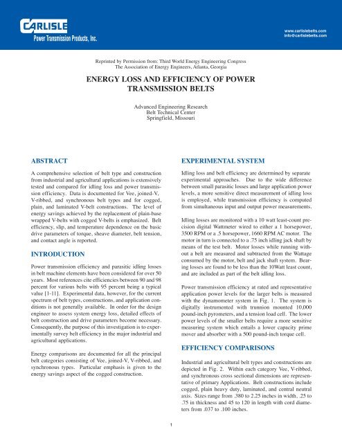
Power <strong>transmission</strong> <strong>efficiency</strong> at rated <strong>and</strong> representative<br />
application <strong>power</strong> levels for the larger <strong>belts</strong> is measured<br />
with the dynamometer system in Fig. 1. The system is<br />
digitally instrumented with trunnion mounted 10,000<br />
pound-inch pyrometers, <strong>and</strong> a tension load cell. The lower<br />
<strong>power</strong> levels <strong>of</strong> the smaller <strong>belts</strong> require a more sensitive<br />
measuring system which entails a lower capacity prime<br />
mover <strong>and</strong> absorber with a 500 pound-inch torque cell.<br />
EFFICIENCY COMPARISONS<br />
Industrial <strong>and</strong> agricultural belt types <strong>and</strong> constructions are<br />
depicted in Fig. 2. Within each category Vee, V-ribbed,<br />
<strong>and</strong> synchronous cross sectional dimensions are representative<br />
<strong>of</strong> primary Applications. Belt constructions include<br />
cogged, plain heavy duty, laminated, <strong>and</strong> central neutral<br />
axis. Sizes range from .380 to 2.25 inches in width, .25 to<br />
.75 in thickness <strong>and</strong> 45 to 120 in length with cord diameters<br />
from .037 to .100 inches.<br />
1
IDLING LOSS<br />
Idling <strong>power</strong> <strong>loss</strong>es for industrial cross sections are listed<br />
in Table 1 as averages <strong>of</strong> generally two tests having<br />
repeatability within the 10 Watt least count. Loss<br />
dependence on tension, diameter, speed, <strong>and</strong> width is<br />
displayed in Fig. 3.<br />
The tension effect results from frictional sliding as a belt<br />
enters <strong>and</strong> exits a pulley; whereas, the diameter dependence<br />
is a consequence <strong>of</strong> bending hysteresis as a belt<br />
flexes from straight span to curved pulley paths. Since<br />
pulley speed controls the rate <strong>of</strong> frictional <strong>and</strong> hysteretic<br />
<strong>energy</strong> dissipation, it is essentially proportional to<br />
<strong>power</strong> <strong>loss</strong>. The influence <strong>of</strong> belt width is due to both<br />
increased frictional <strong>and</strong> bending <strong>loss</strong>es resulting from<br />
multiple industrial <strong>belts</strong>, larger industrial V-belt cross<br />
sections, <strong>and</strong> wider V-ribbed <strong>and</strong> synchronous <strong>belts</strong>.<br />
Bending hysteresis is the principal factor determining<br />
<strong>power</strong> <strong>loss</strong> comparisons between cross sections. Consequently,<br />
due to increased flexibility over plain base <strong>belts</strong><br />
industrial V-belt cogged constructions require the least<br />
<strong>energy</strong> <strong>and</strong> run at lower temperatures under no load.<br />
Reduced cogged hysteresis is reflected by the lower<br />
temperature, although enhanced heat transfer from tooth<br />
turbulence <strong>and</strong> greater convective area is an additional<br />
factor. For similar reasons, especially reduced thickness,<br />
V-ribbed <strong>and</strong> synchronous <strong>belts</strong> are characterized<br />
by progressively less idling <strong>loss</strong> <strong>and</strong> cooler temperature.<br />
Two industrial <strong>belts</strong> exhibit twice the <strong>loss</strong> <strong>of</strong> a single<br />
operating at the same tension per belt. A joined V-belt<br />
has about the same <strong>loss</strong> as two single <strong>belts</strong> in a cogged<br />
construction, but the wrapped joined-V shows significantly<br />
more <strong>loss</strong> than two single wrapped <strong>belts</strong>.<br />
POWER TRANSMISSION EFFICIENCY<br />
Industrial accessory: Energy <strong>loss</strong> during <strong>power</strong> <strong>transmission</strong><br />
at industrial rating application levels is listed in<br />
Table 2. Effect <strong>of</strong> drive torque, diameter, tension, <strong>and</strong><br />
pulley contact is shown in Fig. 4 for industrial cogged<br />
<strong>and</strong> wrapped B-section <strong>belts</strong>. Number <strong>of</strong> tests for each<br />
condition range from 4 to 100 with each result averaged<br />
over the final three minutes <strong>of</strong> a half hour period, during<br />
which 320 torque measurements are obtained. Repeatability<br />
is indicated by a st<strong>and</strong>ard deviation <strong>of</strong> one per cent<br />
within the same B-section belt <strong>and</strong> two per cent between<br />
B-section <strong>belts</strong> <strong>of</strong> identical constructions.<br />
<strong>efficiency</strong> advantage shown in Fig. 4, <strong>and</strong> is the reason the<br />
advantage is maximum at smaller diameters. The cogged<br />
<strong>belts</strong> demonstrated lower slip level further augments its<br />
<strong>efficiency</strong> <strong>and</strong> temperature performance. Industrial Vee<br />
<strong>and</strong> V-ribbed <strong>belts</strong>, sizes <strong>and</strong> constructions are compared<br />
for varying diameters with V-ribbed <strong>and</strong> cogged advantages<br />
being greatest at smaller diameters. The accessory<br />
<strong>belts</strong> temperature performance is presented as a function<br />
<strong>of</strong> slip <strong>and</strong> torque levels.<br />
Agricultural variable speed: Efficiency, slip, <strong>and</strong> temperature<br />
characterize the performance <strong>of</strong> large agricultural<br />
<strong>belts</strong> employed in the dem<strong>and</strong>ing propulsion <strong>and</strong> grain<br />
separation applications <strong>of</strong> high capacity combines. Testing<br />
levels ranged to 150 horse<strong>power</strong> corresponding to<br />
peak field conditions.<br />
As shown in Fig. 6, both cogged <strong>and</strong> wrapped <strong>belts</strong> exhibit<br />
efficiencies above 90 per cent, although cogged <strong>belts</strong><br />
generally display higher <strong>efficiency</strong>, lower slip, <strong>and</strong> cooler<br />
temperatures. Cogged efficiencies are above 94 per cent<br />
throughout the application <strong>power</strong> range.<br />
CONCLUSIONS<br />
Median <strong>efficiency</strong> <strong>of</strong> the surveyed industrial <strong>and</strong> agricultural<br />
belt types <strong>and</strong> constructions is 96 per cent. Within<br />
rated <strong>and</strong> application <strong>power</strong> levels, <strong>efficiency</strong> ranges from<br />
90 to 99 per cent depending on belt type, construction, <strong>and</strong><br />
application parameters. Both median <strong>and</strong> range agree with<br />
historical data.<br />
The major portion <strong>of</strong> belt <strong>energy</strong> <strong>loss</strong> during <strong>power</strong> <strong>transmission</strong><br />
is attributed to parasitic bending hysteresis <strong>and</strong><br />
sliding friction. The cogged construction which minimizes<br />
the hysteretic component <strong>of</strong> parasitic <strong>loss</strong> yields the<br />
greatest <strong>efficiency</strong> in each industrial test. The condition <strong>of</strong><br />
classical B-section cogged <strong>belts</strong> operating on 3.4 inch<br />
diameters at rated <strong>power</strong> levels demonstrated the largest<br />
<strong>energy</strong> savings, ranging from 3 to 6 per cent.<br />
ACKNOWLEDGEMENT<br />
The authors respectfully acknowledge the contribution <strong>of</strong><br />
Mr. C.A. Stiles for the data collection <strong>and</strong> reduction.<br />
Tabulated <strong>transmission</strong> <strong>loss</strong>es <strong>of</strong> industrial A <strong>and</strong> B-section<br />
<strong>belts</strong> from Table 2 along with industrial Vee <strong>and</strong> V-<br />
ribbed <strong>belts</strong> are approximately 75 percent accounted for<br />
by the idling <strong>loss</strong>es listed in Table 1; whereas, idling <strong>loss</strong><br />
accounts for about 50 percent <strong>of</strong> the synchronous belt<br />
<strong>transmission</strong> <strong>loss</strong>es. Lower cogged idling hysteretic <strong>loss</strong><br />
is the primary explanation for the B cogged to wrapped<br />
2
REFERENCES<br />
1. Palmer, R.S.J., <strong>and</strong> Bear, J.H.F., “Mechanical Efficiency<br />
<strong>of</strong> a Variable Speed, Fixed-Center V-Belt Drive,” Journal<br />
<strong>of</strong> Engineering for Industry, Trans. ASME<br />
2. “In Designing a Belt Drive, Consider Bearing <strong>and</strong> Belt<br />
Losses,” Product Engineering<br />
3. Wallin, A.W., “Efficiency <strong>of</strong> Synchronous Belts <strong>and</strong> V-<br />
Belts,” Proceedings <strong>of</strong> National Conference on Power<br />
Transmission, Vol. 5, Illinois Institute <strong>of</strong> Technology<br />
4. Breig, W.F., <strong>and</strong> Oliver, L.R., “Efficiency, Torque Capability,<br />
<strong>and</strong> Tensioning <strong>of</strong> Synchronous Belts,” Proceedings<br />
<strong>of</strong> National Conference on Power Transmission, Vol. 5,<br />
Illinois Institute <strong>of</strong> Technology<br />
5. Williams, W.A., Mechanical Power Transmission Manual,<br />
Conover Mast Publications, New York<br />
6. Pronin, B.A., <strong>and</strong> Shmelev, A.N., “Losses in a Wide-<br />
Belt Variable Speed Drive,” Russian Engineering Journal,<br />
Vol. L, No. 9<br />
7. Pronin, B.A., <strong>and</strong> Lapshina, N.V., “Multi V-Belt<br />
Drives,” Russian Engineering Journal, Vol. LI, No. 1 .<br />
8. Norman, C.A., “High Speed Belt Drives,” Engineering<br />
Experiment Station Bulletin No. 83, Ohio State University<br />
Studies Engineering Series, Vol. III, No. 2<br />
9. Marks St<strong>and</strong>ard H<strong>and</strong>book for Mechanical Engineers,<br />
8 th ed., T. Baumeister, Ed., McGraw-Hill, New York,<br />
10. “Mechanical Efficiency <strong>of</strong> Power Transmission Belt<br />
Drives,” Power Transmission Belt Technical Bulletin, IP-<br />
3-13, Rubber Manufacturers Association,<br />
Washington, D.C.<br />
Regenerative Industrial Drive System<br />
150 HP<br />
DC Motor<br />
Silicon<br />
Controlled<br />
Rectifier<br />
150 HP<br />
DC Generator<br />
Reaction Torque<br />
Sensor<br />
Excitation<br />
& Digital<br />
Display<br />
Reaction Torque<br />
Sensor<br />
Radiation<br />
Pyrometers<br />
Pneumatic Belt<br />
Tensioner<br />
Trunnion<br />
Mount<br />
Magnetic<br />
Picups<br />
Universial<br />
Digital<br />
Counter<br />
Trunnion<br />
Mount<br />
Load Cell<br />
Fig 1. Instrumented Belt Test Dynameter<br />
3
Fig. 2 Belt Types <strong>and</strong> Constuction<br />
INDUSTRIAL BELTS<br />
Cogged Belt Wrapped Belt Joined Belt<br />
Cogged Belt Plain Heavy Duty 3-Ply Laminated Centeral Neutral Axis<br />
V-Ribbed Belt<br />
Synchronous Belt<br />
4
Table 1 Idling Power Loss<br />
4.75 Nominal Diameter (In.) 2.75 Nominal Diameter (In.)<br />
3500 RPM 3500 RPM 1660 RPM<br />
50 Total Tension 100 Total Tension 150 Total Tension 100 Total Tension 100 Total Tension<br />
Belt Cross Section (LBS) (LBS) (LBS) (LBS) (LBS)<br />
DR <strong>and</strong> DN Temp Above Temp Above Temp Above DR <strong>and</strong> DN Temp Above Temp Above<br />
Pitch Dia Power Loss Ambient Power Loss Ambient Power Loss Ambient Pitch Dia Power Loss Ambient Power Loss Ambient<br />
(In) Watts HP (ºF) Watts HP (ºF) Watts HP (ºF) (In) Watts HP (ºF) Watts HP (ºF)<br />
INDUSTRIAL<br />
Classical-V<br />
A 4.6 164 .22 28 176 .24 30 223 .30 36 3.0 214 .29 38 110 .15 33<br />
A Cog 93 .12 17 133 .18 18 166 .22 27 132 .18 25 76 .10 24<br />
2A -- -- -- 243 .33 43 315 .42 48 305 .41 44 151 .20 42<br />
2A Cog -- -- -- 177 .24 21 207 .28 24 192 .26 24 86 .12 20<br />
B 5.0 216 .29 34 250 .34 46 298 .40 46 3.4 262 .35 54 149 .20 44<br />
B Cog 120 .16 18 168 .23 19 214 .29 32 183 .25 28 94 .13 25<br />
2B -- -- -- 365 .49 44 487 .65 59 373 .50 60 195 .26 50<br />
2B Cog -- -- -- 223 .30 25 273 .37 31 237 .32 31 125 .17 27<br />
B Wrapped Joined-V, 2-Rib -- -- -- 490 .66 53 552 .74 63 521 .70 59 277 .37 46<br />
B Cog Joined-V, 2-Rib -- -- -- 245 .33 24 269 .36 26 241 .32 29 131 .18 21<br />
Synchronous<br />
L038 4.775 32 .04 5 49 .07 7 81 .11 12 2.387 48 .06 16 29 .04 13<br />
L075 41 .05 6 53 .07 8 70 .09 10 53 .07 14 28 .04 10<br />
H050 5.093 61 .08 8 67 .09 10 92 .12 10 2.546 68 .09 19 36 .05 13<br />
H075 76 .10 11 98 .13 12 105 .14 14 90 .12 22 44 .06 15<br />
H100 84 .11 11 113 .15 14 138 .18 16 112 .15 28 47 .06 15<br />
5
300<br />
46<br />
300<br />
54<br />
250<br />
46<br />
250<br />
46<br />
IDLING POWER LOSS (WATTS)<br />
200<br />
150<br />
100<br />
18<br />
34 = Temperature (˚F)<br />
Above Ambient<br />
31<br />
19<br />
32<br />
200<br />
150<br />
100<br />
28<br />
19<br />
50<br />
3500 RPM<br />
4.75 Nominal Pitch Dia (In)<br />
50<br />
3500 RPM<br />
100 Total Tension (Lb)<br />
0<br />
300<br />
50 100 150 2 3 4 5<br />
TOTAL TENSION (LB)<br />
PITCH DIAMETER (IN)<br />
600<br />
250<br />
2.75 Nominal Pitch Dia (In)<br />
100 Total Tension (Lb)<br />
54<br />
500<br />
B Cog (5.0, 3.4 in. Dia.)<br />
B Wrapped<br />
B Cog Joined-V, 2-Rib<br />
B Wrapped Joined-V, 2 Rib<br />
59<br />
IDLING POWER LOSS (WATTS)<br />
200<br />
150<br />
100<br />
44<br />
25<br />
28<br />
400<br />
300<br />
200<br />
54<br />
28<br />
59<br />
60<br />
29<br />
50<br />
100<br />
2.75 Nominal Pitch Dia (In)<br />
100 Total Tension (Lb)<br />
0<br />
1660 3500 .3 .5 .7 .9 1.1 1.3<br />
PULLEY SPEED (RPM)<br />
BELT TOP WIDTH (IN)<br />
Fig. 3 Idling Power Loss Dependence on Tension, Diameter, Speed <strong>and</strong> Width<br />
6
Table 2 Industrial Belt Efficiency at Rated Power<br />
Temp Above<br />
Percent Horse<strong>power</strong> Percent Ambient DR <strong>and</strong> DN Rated Total<br />
Belt Cross Section Efficiency Loss Slip (ºF) Pitch Dia Torque Tension Nominal No. <strong>of</strong><br />
Wrap Cog Wrap Cog Wrap Cog Wrap Cog (In) (Lb-Ft) (Lbs) RPM Tests<br />
Classical-V<br />
A 91.4 93.4 .17 .13 1.26 1.03 33 21 3.0 5.5 P^ 66 1750 32<br />
A 90.6 93.2 .25 .17 1.31 .98 39 22 7.1 C 85 16<br />
2A 90.7 93.3 .38 .27 1.34 1. 48 28 11.0 P 132 16<br />
A 97.3 97.7 0.16 0.14 0.67 0.4 15 9 6.2 16.7 P 97 8<br />
A 96.9 97.5 .23 .18 .77 .56 22 12 21.2 C 123 8<br />
B 90.8 95.6 .12 .11 1.34 .79 23 14 3.4 3.9 S 42 1750 38<br />
B 90.1 95.1 .19 .09 1.54 1.06 29 18 5.4 P 57 100<br />
B 92.1 95.3 .32 .19 2.31 1.40 45 27 11.4 C 121 14<br />
2B 89.7 95.7 .30 .12 1.48 .71 29 19 7.8 S 84 12<br />
B Joined-V* 86.2 94.4 .40 .15 1.48 .78 39 18 7.8 S 84 6<br />
B 94.7 96.3 .24 .17 1.28 1.07 26 18 5.0 13.2 S 93 1750 13<br />
B 95.7 96.8 .23 .18 1.45 1.17 28 21 15.7 P 113 36<br />
B 95.9 96.5 .31 .28 1.79 1.40 39 32 21.6 C 156 13<br />
B 96.9 97.5 .23 .18 .85 .64 24 20 6.6 21.1 S 115 1750 10<br />
B 96.9 97.5 .26 .21 .96 .71 29 23 25.0 P 136 10<br />
B 96.9 97.6 .33 .25 1.14 .83 33 28 30.9 C 169 10<br />
C 97.4 99.6 .41 .08 2.04 1.38 42 22 8.0 68.3 C 308 1160 16<br />
2C 97.4 99.3 .58 .16 1.48 1.06 37 20 100.5 P 452 8<br />
5C 97.4 98.9 1.49 .63 1.45 1.01 54 27 251.2 P 1130 16<br />
5C 96.9 98.8 2.37 .99 1.91 1.13 78 38 341.7 C 1538 8<br />
C Joined-V** 97.5 98.5 1.42 .85 1.13 1.17 58 38 251.2 P 1130 8<br />
D 96.9 97.4 .80 .70 .89 .53 37 27 12.0 113.6 P 341 1160 8<br />
4D 96.8 97.5 3.35 2.55 .83 .55 62 45 454.4 P 1364 8<br />
Synchronous<br />
L075 97.0 .05 .00 5 3.342 5.0 50 1750 24<br />
L038 98.2 .04 .00 8 4.775 7.2 50 8<br />
L075 98.1 .05 .00 6 7.2 50 16<br />
L075 97.3 .07 .00 9 7.2 80 15<br />
XH400 99.4 .42 .00 25 8.356 272.2 1040 1750 8<br />
^ S, P, <strong>and</strong> C denote st<strong>and</strong>ard, premium, <strong>and</strong> cog ratings; 1972 Dayco PT H<strong>and</strong>book.<br />
* 2-rib wrapped, 2-rib cog.<br />
** 5-rib wrapped, 4-rib cog.<br />
7
100<br />
98<br />
96<br />
94<br />
92<br />
5/1 Tension Ratio<br />
Cog Cog<br />
Wrapped<br />
180 Contact Angle (Deg)<br />
113 Total Tension (LB)<br />
75 Tension Difference (LB)<br />
56 = Temperature (˚F)<br />
Above Ambient<br />
Wrapped<br />
5.0 Pitch Diameter (IN)<br />
188 Torque (LB-IN)<br />
Cog<br />
Wrapped<br />
5.0 Pitch Diameter (IN)<br />
188 Torque (LB-IN)<br />
113 Total Tension (LB)<br />
PERCENT SLIP PERCENT EFFICIENCY<br />
90<br />
3<br />
2<br />
1<br />
29<br />
14<br />
23<br />
18<br />
45<br />
27<br />
26<br />
68<br />
28<br />
51<br />
39<br />
32<br />
18 21 24<br />
50<br />
29<br />
20 23<br />
40<br />
33<br />
28<br />
44<br />
37<br />
38<br />
21<br />
29<br />
19<br />
21<br />
21<br />
29<br />
25<br />
26<br />
18<br />
19 21<br />
28<br />
27 30<br />
23<br />
22<br />
24<br />
35<br />
24<br />
30<br />
28<br />
21<br />
0<br />
100 200 300 400 500 3.4 5.0 6.6 50 100 150 200 100 140 180<br />
TORQUE (LB-IN) PITCH DIAMETER (IN) TOTAL TENSION (LB) CONTACT ANGLE (DEG)<br />
PITCH DIAMETER (IN.)<br />
Cog<br />
Wrapped<br />
3.4 5.0 6.6<br />
Fig. 4 Comparison <strong>of</strong> cogged <strong>and</strong> wrapped B-section <strong>efficiency</strong>, slip,<br />
<strong>and</strong> temperature at torque, diameter, tension, <strong>and</strong> contact angle<br />
variations about 1750 RPM, 5 In. rated <strong>power</strong><br />
8
PERCENT SLIP PERCENT EFFICIENCY<br />
100<br />
98<br />
96<br />
94<br />
92<br />
90<br />
88<br />
86<br />
8<br />
7<br />
6<br />
4<br />
3<br />
2<br />
97<br />
1<br />
76 82<br />
0<br />
51<br />
59<br />
Temperature (˚F)<br />
Above Ambient = 174<br />
149<br />
125 136<br />
72<br />
1750 RPM<br />
1000 Total Tension (LB)<br />
9.8 Pitch Diameter (IN)<br />
HL COG<br />
HL WRAPPED<br />
(Wrinkled Base)<br />
HL HM - SECTION HN<br />
95<br />
122<br />
149<br />
186<br />
182<br />
79<br />
60<br />
80<br />
67<br />
82<br />
99<br />
138<br />
107<br />
172<br />
132<br />
1600 RPM<br />
1000 Total Tension (LB)<br />
10.8 Pitch Diameter (IN)<br />
HM COG<br />
HM WRAPPED<br />
189<br />
182<br />
172<br />
13.0<br />
186 11.5 = Pitch Diameter (IN)<br />
130<br />
150<br />
140<br />
130<br />
150<br />
HORSEPOWER LOSS<br />
5<br />
4<br />
3<br />
2<br />
1<br />
0<br />
65<br />
20 = Nominal Driver<br />
Horse<strong>power</strong><br />
100<br />
20<br />
65<br />
HN COG<br />
.2 .4 .6 .8 0 .2 .4 .6 .8 0 .2 .4 .6 .8<br />
100<br />
HN Wrapped<br />
(Wrinkled Base)<br />
TRACTION COEFFICIENT = (T1-T2) / (T1+T2)<br />
20<br />
20<br />
75<br />
85<br />
140<br />
1500 RPM<br />
1000 Total Tension (LB)<br />
1200 1400 1600<br />
Fig.6 Agricultural variable speed belt <strong>efficiency</strong>, slip, temperature, <strong>and</strong> <strong>power</strong> <strong>loss</strong><br />
9
Power Transmission Products, Inc.<br />
108086 © Carlisle Power Transmission Products, Inc.<br />
10