Calculux Indoor - Philips Lighting
Calculux Indoor - Philips Lighting
Calculux Indoor - Philips Lighting

Create successful ePaper yourself
Turn your PDF publications into a flip-book with our unique Google optimized e-Paper software.
<strong>Calculux</strong><br />
<strong>Indoor</strong><br />
Version 5.0<br />
<strong>Calculux</strong><br />
<strong>Indoor</strong>
<strong>Calculux</strong><br />
<strong>Indoor</strong>
Contents<br />
<strong>Calculux</strong><br />
<strong>Indoor</strong>
<strong>Calculux</strong><br />
<strong>Indoor</strong>
Contents<br />
1 Introduction 1.1<br />
1.1 <strong>Philips</strong> - your partner in lighting 1.1<br />
1.2 What <strong>Calculux</strong> does 1.1<br />
1.3 What you can do with <strong>Calculux</strong> <strong>Indoor</strong> 1.2<br />
1.4 Tailor make your indoor design 1.2<br />
1.5 Choose from a wide range of luminaires 1.2<br />
1.6 Easy luminaire positioning individually or as a group 1.3<br />
1.7 Symmetry lighting installation 1.3<br />
1.8 Graphical manipulation of generated luminaires and/or aiming positions 1.3<br />
1.9 Calculation Grids 1.3<br />
1.10 Switching Modes 1.4<br />
1.11 Light Regulation Factor (LRF) 1.4<br />
1.12 Save money by optimising cost-effectiveness 1.4<br />
1.13 See your lighting design develop on screen 1.4<br />
1.14 Impress your customers with attractive reports 1.4<br />
1.15 Installation and operating platform 1.5<br />
2 Getting Started 2.1<br />
2.1 Installing the program 2.1<br />
2.2 Installing the database 2.1<br />
2.3 What is new in <strong>Calculux</strong> <strong>Indoor</strong> 5.0 2.2<br />
2.4 Installing other report languages 2.2<br />
2.5 File structure 2.3<br />
2.6 Environment settings and preferences 2.3<br />
3 Background Information 3.1<br />
3.1 Project Info and Vignette file 3.1<br />
3.1.1 Project Info.....................................................................................................................................................3.1<br />
3.1.2 Vignette file....................................................................................................................................................3.1<br />
3.2 Room Characteristics 3.2<br />
3.2.1 Surfaces: dimensions and reflectance...............................................................................................3.2<br />
3.2.2 Interreflection accuracy...........................................................................................................................3.2<br />
3.2.3 Quick Estimate.............................................................................................................................................3.3<br />
3.2.4 UF Method.....................................................................................................................................................3.3<br />
3.2.5 Zones................................................................................................................................................................3.4<br />
3.2.6 Room Grids...................................................................................................................................................3.5<br />
3.3 Application Fields 3.6<br />
3.3.1 General ............................................................................................................................................................3.6<br />
3.3.2 Connections with calculation Grids..................................................................................................3.7<br />
3.4 Luminaire Photometric Data 3.8<br />
3.4.1 Luminaire Database...................................................................................................................................3.8<br />
3.4.2 ASCII data file...............................................................................................................................................3.8<br />
<strong>Calculux</strong><br />
<strong>Indoor</strong>
Contents<br />
3.5 Luminaire Positioning and Orientation 3.9<br />
3.5.1 Luminaire Positioning ...............................................................................................................................3.9<br />
XYZ-coordinates........................................................................................................................................3.9<br />
C-γ coordinate system.............................................................................................................................3.9<br />
3.5.2 Luminaire Orientation...........................................................................................................................3.10<br />
Aiming types...............................................................................................................................................3.10<br />
Luminaire orientation order ..............................................................................................................3.12<br />
Conversion of Aiming types..............................................................................................................3.13<br />
Selecting Aiming Presentation types.............................................................................................3.14<br />
Aiming offset (Floodlights)..................................................................................................................3.15<br />
3.5.3 Number of luminaires per position (Luminaire Quantity)................................................3.16<br />
3.6 Individual Luminaires 3.17<br />
3.6.1 General .........................................................................................................................................................3.17<br />
3.6.2 Luminaire Definition...............................................................................................................................3.17<br />
Luminaire List.............................................................................................................................................3.17<br />
3.6.3 View................................................................................................................................................................3.18<br />
3.7 Luminaire Arrangements 3.19<br />
3.7.1 General .........................................................................................................................................................3.19<br />
Arrangement Definition.......................................................................................................................3.19<br />
Luminaire Definition...............................................................................................................................3.20<br />
Luminaire List.............................................................................................................................................3.20<br />
View................................................................................................................................................................3.20<br />
3.7.2 Room Block Arrangement..................................................................................................................3.20<br />
Arrangement Definition.......................................................................................................................3.20<br />
Luminaire Definition...............................................................................................................................3.22<br />
3.7.3 Block Arrangement.................................................................................................................................3.23<br />
Arrangement Definition.......................................................................................................................3.23<br />
Luminaire Definition...............................................................................................................................3.25<br />
3.7.4 Polar Arrangement .................................................................................................................................3.26<br />
Arrangement Definition.......................................................................................................................3.26<br />
Luminaire Definition...............................................................................................................................3.28<br />
3.7.5 Line Arrangement ...................................................................................................................................3.30<br />
Arrangement Definition.......................................................................................................................3.30<br />
Luminaire Definition...............................................................................................................................3.33<br />
3.7.6 Free Arrangement...................................................................................................................................3.34<br />
Arrangement Definition.......................................................................................................................3.34<br />
Luminaire Definition...............................................................................................................................3.34<br />
3.7.7 Ungrouping a luminaire arrangement...........................................................................................3.35<br />
3.7.8 Convert into a Free Arrangement .................................................................................................3.35<br />
3.8 Symmetry 3.36<br />
3.8.1 General .........................................................................................................................................................3.36<br />
3.8.2 X-Symmetry ...............................................................................................................................................3.38<br />
3.8.3 Y-Symmetry................................................................................................................................................3.38<br />
3.8.4 XY-Symmetry............................................................................................................................................3.39<br />
3.9 Grids 3.40<br />
3.9.1 General .........................................................................................................................................................3.40<br />
3.9.2 Generated grids........................................................................................................................................3.40<br />
<strong>Calculux</strong> standard grids ........................................................................................................................3.40<br />
Room Surfaces..........................................................................................................................................3.41<br />
NEN standard grids................................................................................................................................3.41<br />
DIN standard grids .................................................................................................................................3.42<br />
CIBSE standard grids..............................................................................................................................3.42<br />
<strong>Calculux</strong><br />
<strong>Indoor</strong>
Contents<br />
3.9.3 User defined (Free added) grids .....................................................................................................3.43<br />
Size and position of a grid: points A, B and C .........................................................................3.43<br />
Calculation points in a grid.................................................................................................................3.45<br />
Default side.................................................................................................................................................3.46<br />
Grid coupling .............................................................................................................................................3.46<br />
Normal vector of a grid.......................................................................................................................3.50<br />
Presentation of results ..........................................................................................................................3.50<br />
3.10 Shapes 3.52<br />
3.10.1 Pre-defined shapes..................................................................................................................................3.52<br />
3.10.2 User-defined shapes...............................................................................................................................3.52<br />
Set of points...............................................................................................................................................3.53<br />
Rectangle......................................................................................................................................................3.53<br />
Polygon .........................................................................................................................................................3.54<br />
Arc...................................................................................................................................................................3.55<br />
3.10.3 Symmetry.....................................................................................................................................................3.56<br />
3.11 <strong>Lighting</strong> control (Switching Modes / Light Regulation Factor) 3.57<br />
3.11.1 Switching Modes......................................................................................................................................3.57<br />
3.11.2 Light Regulation Factor (LRF) ...........................................................................................................3.57<br />
3.12 Drawings 3.58<br />
3.13 Light-technical Calculations 3.59<br />
3.13.1 Plane Illuminance......................................................................................................................................3.59<br />
3.13.2 Glare...............................................................................................................................................................3.62<br />
UGR................................................................................................................................................................3.63<br />
3.13.3 Indirect contribution ..............................................................................................................................3.65<br />
3.13.4 Calculating the numbers of luminaires needed.......................................................................3.65<br />
Quick Estimation......................................................................................................................................3.65<br />
Utilisation Factor (UF)...........................................................................................................................3.66<br />
Uniformity Check....................................................................................................................................3.67<br />
3.13.5 Quality Figures ..........................................................................................................................................3.67<br />
Minimum ......................................................................................................................................................3.67<br />
Maximum.....................................................................................................................................................3.67<br />
Minimum/maximum...............................................................................................................................3.67<br />
Minimum/average....................................................................................................................................3.67<br />
3.14 Report Setup 3.68<br />
3.15 Cost Calculations 3.69<br />
3.15.1 Total Investment......................................................................................................................................3.69<br />
3.15.2 Annual costs...............................................................................................................................................3.70<br />
3.16 Maintenance Factor/New Value Factor 3.72<br />
3.16.1 General Project Maintenance Factor............................................................................................3.72<br />
3.16.2 Luminaire Type Maintenance Factor.............................................................................................3.72<br />
3.16.3 Lamp Maintenance Factor ..................................................................................................................3.72<br />
<strong>Calculux</strong><br />
<strong>Indoor</strong>
Contents<br />
Appendix<br />
A1<br />
My First Project<br />
Contains a step-by-step tutorial that takes you through the process of creating an <strong>Indoor</strong><br />
field lighting project.<br />
A2<br />
My Second Project<br />
Contains a step-by-step tutorial that takes you through the process of adding furniture and<br />
additional lighting to the indoor lighting installation.<br />
A3<br />
My Third Project<br />
Contains a step-by-step tutorial that takes you through the process of creating a director<br />
room, with furniture and additional lighting.<br />
A4<br />
My First Project printed report<br />
Contains a printed report of your first project. When you complete and print out My First<br />
Project this is what you should get.<br />
A5<br />
My Second Project printed report<br />
Contains a printed report of your second project. When you complete and print out My<br />
Second Project this is what you should get.<br />
A6<br />
My Third Project printed report<br />
Contains a printed report of your third project. When you com-plete and print out My<br />
Third Project this is what you should get.<br />
A7<br />
Index<br />
<strong>Calculux</strong><br />
<strong>Indoor</strong>
Chapter 1<br />
Introduction<br />
<strong>Calculux</strong><br />
<strong>Indoor</strong>
<strong>Calculux</strong><br />
<strong>Indoor</strong>
Chapter 1 Introduction<br />
1 Introduction<br />
This chapter describes the main features of <strong>Calculux</strong> <strong>Indoor</strong> and explains what you can<br />
expect from the package.<br />
<strong>Calculux</strong> <strong>Indoor</strong> is a software tool which can help lighting designers select and evaluate<br />
lighting systems for office and industrial applications. Speed, ease of use and versatility are<br />
features of the package from <strong>Philips</strong> <strong>Lighting</strong>, the world's leading supplier of lighting<br />
systems. Running under the Microsoft Windows operating system, <strong>Calculux</strong> <strong>Indoor</strong><br />
includes even more options than its popular predecessor, <strong>Calculux</strong> for DOS.<br />
<strong>Calculux</strong> <strong>Indoor</strong> is part of the <strong>Philips</strong> <strong>Calculux</strong> line, covering indoor, area and road<br />
applications.<br />
1.1 <strong>Philips</strong> - your partner in lighting<br />
<strong>Philips</strong> <strong>Lighting</strong>, established over a century ago, has vast experience in helping customers<br />
to select the optimum solutions for their lighting applications, in terms of quality,<br />
performance and economy.<br />
Our customer partnership philosophy means that we can support you from the planning,<br />
design and commissioning of projects, right through to realisation and aftersales support.<br />
This philosophy maximises cost-efficiency by ensuring the ability to choose the most<br />
suitable equipment for your application.<br />
<strong>Philips</strong> <strong>Lighting</strong> Design and Application Centres situated throughout the world offer<br />
extensive consultancy, training and demonstration services. Our lighting specialists can<br />
recommend existing solutions or develop new tailor made solutions for your application.<br />
Because <strong>Philips</strong> <strong>Lighting</strong> is the leading supplier, you're assured of getting the best support<br />
available.<br />
<strong>Calculux</strong> is part of that support. For consultants, wholesalers and installers wishing to<br />
develop lighting designs, it's the ideal tool; saving time and effort, providing the most<br />
advanced lighting solutions available and guaranteeing satisfied customers.<br />
1.2 What <strong>Calculux</strong> does<br />
<strong>Calculux</strong> is a very flexible system which offers lighting designers a wide range of options:<br />
• You can use the package to simulate real lighting situations and analyse different lighting<br />
installations until you find the solutions which suits your technical as well as your<br />
financial and aesthetic requirements best.<br />
• <strong>Calculux</strong> uses luminaires from an extensive <strong>Philips</strong> database and photometric data which is<br />
stored in the <strong>Philips</strong> Phillum external formats. Additionally other luminaire data formats<br />
can be imported (CIBSE/TM14, IES, EULUMDAT and LTLI).<br />
• Simple menus, logical dialogue boxes and a step by step approach help you to find the<br />
most efficient and cost-effective solutions for your lighting applications.<br />
<strong>Calculux</strong><br />
- 1.1 -<br />
<strong>Indoor</strong>
Chapter 1 Introduction<br />
1.3 What you can do with <strong>Calculux</strong> <strong>Indoor</strong><br />
• Perform lighting calculations (including direct, indirect, total and average illuminance)<br />
within orthogonal rooms;<br />
• Predict financial implications including energy, investment, lamp and maintenance costs<br />
for different luminaire arrangements;<br />
• Select luminaires from an extensive <strong>Philips</strong> database or from specially formatted files for<br />
luminaires from other suppliers;<br />
• Specify room dimensions, luminaire types, maintenance factors, interreflection accuracy,<br />
calculation grids and calculation types;<br />
• Compile reports displaying results in text and graphical formats;<br />
• Support Switching modes and Light regulation factors;<br />
• Support multiple languages.<br />
The logical steps used for project specification save you time and effort, while the report<br />
facility gives you the opportunity to keep permanent records of the results.<br />
1.4 Tailor make your indoor design<br />
<strong>Calculux</strong> <strong>Indoor</strong> is designed for use with six-sided orthogonal rooms. The dimensions of<br />
the room and the reflectance of each surface are entered by the user. Calculation grids can<br />
be defined anywhere in the room. You can also enter the maintenance factor and the<br />
required interreflection accuracy. These values will be used in all subsequent calculations.<br />
1.5 Choose from a wide range of luminaires<br />
<strong>Calculux</strong> is supplied with an extensive <strong>Philips</strong> database which includes the most advanced<br />
luminaires. For each luminaire you can view luminaire data, including the type of<br />
distributor, lamp type, output flux efficiency factors and power consumption. The light<br />
distribution can be shown in a Polar, Cartesian or Isocandela diagram, together with the<br />
luminaire quality figures.<br />
Apart from the <strong>Philips</strong> database, the following other well known luminaire data formats<br />
from other suppliers can be used in <strong>Calculux</strong>:<br />
• CIBSE/TM14;<br />
• EULUMDAT;<br />
• IES;<br />
• LTLI.<br />
<strong>Calculux</strong><br />
- 1.2 -<br />
<strong>Indoor</strong>
Chapter 1 Introduction<br />
1.6 Easy luminaire positioning individually or as a group<br />
After you've made your luminaire selection, you can position and orientate luminaires<br />
individually or in groups, anywhere in a room. Luminaire data, including the type of<br />
distributor, lamp type, output flux and power consumption can be viewed at any time.<br />
In many lighting designs luminaires are often grouped in arrangements such as blocks,<br />
lines or circles. <strong>Calculux</strong> <strong>Indoor</strong> contains an option to define a number of arrangements.<br />
The position of the luminaires in such an arrangement is controlled by the arrangement<br />
rule but the orientation of each luminaire within an arrangement can be altered. It's even<br />
possible to free the luminaires positions so that they're no longer connected via the<br />
arrangement rule. This feature proves very useful e.g. when in a preliminary design a<br />
number of luminaires are placed on a line, but in the final stage one of the luminaires in<br />
the line doesn't entirely fulfil the line arrangement rule.<br />
1.7 Symmetry lighting installation<br />
Many designs contain a symmetric lighting installation. This simplifies luminaire<br />
arrangement entries where one or more of the luminaires have the same orientation.<br />
<strong>Calculux</strong> offers the possibility to include symmetry in the installation or a part of the<br />
installation.<br />
1.8 Graphical manipulation of generated luminaires and/or<br />
aiming positions<br />
Having defined luminaires as individuals or in arrangements, <strong>Calculux</strong> enables graphical<br />
manipulation (with a mouse) of the position and orientation of the luminaires.<br />
Graphical manipulation operates with the same arrangement rules.<br />
1.9 Calculation Grids<br />
After setting the luminaire arrangement, you're able to choose a preset grid or define your<br />
own for which the lighting calculations will be carried out. For example you wish to know<br />
if a particular combination of luminaires provides a sufficient level of light for a secretary's<br />
desk.<br />
By defining the desktop as a grid, the illuminance can be calculated and the results viewed<br />
on screen or printed. There's even a possibility to specify the number of points on the<br />
desktop at which the illuminance is calculated. On the other hand, if you don't want to<br />
define your own grid, frequently used grids corresponding to the room's six surfaces and<br />
the working plane are predefined to save you time.<br />
In many situations the indirect illuminance can be calculated by considering the room<br />
surfaces as diffuse sources which reflect the same amount of light at every point. When<br />
more accuracy is required, <strong>Calculux</strong> <strong>Indoor</strong> allows you to divide the room surfaces into<br />
cells which may reflect varying amounts of light. Up to 800 cells can be defined to give an<br />
extremely high level of accuracy.<br />
<strong>Calculux</strong> <strong>Indoor</strong> also provides a quick estimate of the number of luminaires of a particular<br />
type needed to provide a certain level of illuminance using the Utilisation Factor method.<br />
<strong>Calculux</strong><br />
- 1.3 -<br />
<strong>Indoor</strong>
Chapter 1 Introduction<br />
1.10 Switching Modes<br />
<strong>Calculux</strong> <strong>Indoor</strong> enables you to develop a lighting design in different switching modes.<br />
You can first generate a design for a conference room for video presentation and then by<br />
adding luminaires go on to generate a design for a conference situation.<br />
1.11 Light Regulation Factor (LRF)<br />
This <strong>Calculux</strong> option enables you to dim luminaires or luminaire arrangements<br />
1.12 Save money by optimising cost-effectiveness<br />
Cost is a major consideration when specifying a lighting installation. <strong>Calculux</strong> provides a<br />
breakdown of the costs you can expect to incur with a particular installation, both in terms<br />
of initial investment and annual running costs. Thus it's possible to support you in the<br />
decision making process by comparing the cost-effectiveness of different lighting<br />
arrangements.<br />
1.13 See your lighting design develop on screen<br />
A special view menu is provided to enable you to monitor the development of your project<br />
on screen. A 3-D as well as a number of 2-D project overviews can be displayed on screen.<br />
All overviews allow graphical manipulation of the luminaires (position and orientation).<br />
The view facility can also be used to study the calculated results in text and graphic format.<br />
Tables listing the calculated values are displayed. The view facility can also provide<br />
isotropic contours, mountain plots and graphic tables of the results.<br />
1.14 Impress your customers with attractive reports<br />
When you've finished a project you're able to generate attractive reports giving the results<br />
of the calculations. All you have to do is use the menu to select the elements which you<br />
wish to include in your report and they will be added automatically.<br />
For example, you can incorporate:<br />
• A table of contents;<br />
• 2-D and 3-D project overviews;<br />
• Summary;<br />
• Luminaire information (including Polar or Cartesian diagram);<br />
• Detailed information about the calculation results (in textual table, graphical presentation<br />
and/or Iso contour);<br />
• Financial data.<br />
It's also possible to add supplementary text. A convenient feature if you wish to comment<br />
on or draw conclusions from the results presented in the report.<br />
<strong>Calculux</strong><br />
- 1.4 -<br />
<strong>Indoor</strong>
Chapter 1 Introduction<br />
1.15 Installation and operating platform<br />
<strong>Calculux</strong> for indoor, area and road applications are supplied with the installation program<br />
and database.<br />
The following target operating platform is recommended:<br />
• CPU: Pentium 350;<br />
• RAM:<br />
128 Mb;<br />
• Hard disk: 100 Mb free disk space;<br />
• Operating system: Windows 98 or later;<br />
• Other:<br />
SVGA monitor, mouse, Windows supported graphics printer or plotter.<br />
<strong>Calculux</strong><br />
- 1.5 -<br />
<strong>Indoor</strong>
Chapter 1 Introduction<br />
<strong>Calculux</strong><br />
- 1.6 -<br />
<strong>Indoor</strong>
Chapter 2<br />
Getting Started<br />
<strong>Calculux</strong><br />
<strong>Indoor</strong>
<strong>Calculux</strong><br />
<strong>Indoor</strong>
Chapter 2 Getting Started<br />
2 Getting Started<br />
This section tells you which steps you should follow to install <strong>Calculux</strong> on your personal<br />
computer.<br />
The installation procedure of <strong>Calculux</strong> consists of two steps:<br />
2.1 Installing the program<br />
In order to install <strong>Calculux</strong> correctly, please stop all other applications before starting the<br />
installation.<br />
To install the program:<br />
• Start Windows.<br />
• Insert the CD in the CD-ROM drive of your computer.<br />
• From the Windows Start menu, select Run.<br />
• When the Run dialogue box appears, click Browse.<br />
• On your CD-ROM drive, select setup.<br />
• Click OK.<br />
• Follow the instructions on screen.<br />
(You can also use Windows Write to read the Readme file, which is stored in the <strong>Calculux</strong><br />
directory.<br />
Uninstalling the package:<br />
• From the Windows Start menu, select Settings > Control Panel.<br />
• Double click the Add/Remove Programs icon.<br />
• Select <strong>Calculux</strong> <strong>Indoor</strong>, click on the Add/Remove button and follow the instructions.<br />
2.2 Installing the database<br />
To install the database, you need the CD labeled 'Database'.<br />
• Start Windows.<br />
• Insert the CD in the CD-ROM drive of your computer.<br />
• From the Windows Start menu, select Run.<br />
• When the Run dialogue box appears, click Browse.<br />
• On your CD-ROM drive, select setup.<br />
• Click OK.<br />
• Follow the instructions on screen.<br />
<strong>Calculux</strong><br />
- 2.1 -<br />
<strong>Indoor</strong>
Chapter 2 Getting Started<br />
2.3 What is new in <strong>Calculux</strong> <strong>Indoor</strong> 5.0<br />
<strong>Calculux</strong> <strong>Indoor</strong> 5.0 is an upgrade of <strong>Calculux</strong> <strong>Indoor</strong> 4.0. Major new and enhanced<br />
features are:<br />
• Import luminaire data formats from other suppliers (CIBSE/TM14, EULUMDAT, IES and<br />
LTLI);<br />
• Copy and paste feature for table input data;<br />
• Copy graphical output to the clipboard to be used in other programs;<br />
• Generate shapes for the Ice-hockey field;<br />
• In/outbound polygon shapes;<br />
• Shape definition in xy coordinates;<br />
• Draw luminaire object with geometrical or optical luminaire dimensions;<br />
• Use preferred lamp colour from luminaire database.<br />
(Project files (*.CIN) are upwards compatible. They can be used in the new releases.<br />
However, after saving, they cannot be used anymore in previous releases.<br />
2.4 Installing other report languages<br />
<strong>Calculux</strong> supports run-time selection of the report language.<br />
To do so, each language requires an additional language file to be installed in the<br />
application folder of <strong>Calculux</strong> <strong>Indoor</strong>.<br />
All available report languages are installed automatically during installation.<br />
When an extra language must be installed, the required file (named CIN_*.RPT) must be<br />
copied into this folder (e.g. C:\Program Files\<strong>Calculux</strong>\<strong>Indoor</strong>).<br />
(In Windows 98 it can be necessary to enable Multilanguage Support:<br />
• Choose Add/Remove Programs in the Control Panel.<br />
• Go to Windows Setup and enable Multilanguage Support.<br />
<strong>Calculux</strong><br />
- 2.2 -<br />
<strong>Indoor</strong>
Chapter 2 Getting Started<br />
2.5 File structure<br />
During the installation procedure a number of directories will be created. The default<br />
directory structure, which should be created during the installation of the program and the<br />
database, is described below.<br />
C: \PROGRAM FILES\CALCULUX<br />
\INDOOR<br />
\DB<br />
\MULTLANG<br />
\PHILLUM<br />
\PROJECT<br />
\VIGNETTE<br />
• In the INDOOR directory, the program and its necessary files are stored.<br />
• In the DB directory, the database is installed.<br />
• In the MULTLANG directory, the different language versions of the package (if available)<br />
are stored.<br />
• In the PHILLUM directory, the individual photometric data files, not available in the<br />
database, (i.e. Phillum) are stored. The program is supplied with a few test Phillum files.<br />
• In the PROJECT directory, the projects can be stored.<br />
• In the VIGNETTE directory, the files (Vignette files) containing the company names and<br />
addresses are stored. The program is supplied with a few test vignettes.<br />
For more detailed information relating to each of the above directories, use the Readme<br />
icon.<br />
2.6 Environment settings and preferences<br />
When the program and database are installed successfully, you can start the application<br />
and use the Environment Options in the Option menu to set the environment directories<br />
and database settings.<br />
The environment directories and database settings can be checked at any time.<br />
You are now ready to start developing your first lighting project.<br />
<strong>Calculux</strong><br />
- 2.3 -<br />
<strong>Indoor</strong>
Chapter 2 Getting Started<br />
<strong>Calculux</strong><br />
- 2.4 -<br />
<strong>Indoor</strong>
Chapter 3<br />
Background<br />
Information<br />
<strong>Calculux</strong><br />
<strong>Indoor</strong>
<strong>Calculux</strong><br />
<strong>Indoor</strong>
Chapter 3 Background Information<br />
3 Background Information<br />
This chapter describes in detail the background principles used in <strong>Calculux</strong>.<br />
3.1 Project Info and Vignette file<br />
3.1.1 Project Info<br />
When you start a new project in <strong>Calculux</strong>, it can be beneficial to enter summary<br />
information. This can include remarks and statistics about the project, e.g. name, date and<br />
designer, as well as customer details.<br />
3.1.2 Vignette file<br />
<strong>Calculux</strong> enables you to include details about yourself and your company in your reports.<br />
The information will be printed on the cover page of the reports and can be used for<br />
reference at any time.<br />
This provides the customer with contact details, should they need to consult you over the<br />
contents of the report.<br />
If you create what is called a Vignette file you can save the information to a disk.<br />
This eliminates the need to enter the same company information every time you open a<br />
new project. You can simply select the Vignette file to be included in your next project.<br />
<strong>Calculux</strong><br />
- 3.1 -<br />
<strong>Indoor</strong>
Chapter 3 Background Information<br />
3.2 Room Characteristics<br />
3.2.1 Surfaces: dimensions and reflectance<br />
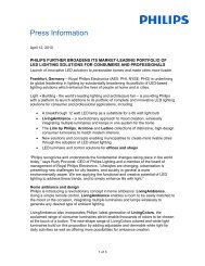
<strong>Calculux</strong> <strong>Indoor</strong> assumes that the room in which the luminaires are to be positioned is<br />
rectangular. Rooms are defined by using an XYZ-coordinate system in which the width is<br />
parallel to the x-axis, the length is parallel to the y-axis and the height is parallel to the z-<br />
axis.<br />
For positioning of the room the X and Y coordinates of the front bottom left corner of the<br />
room can be entered (P) you can press the 'Centre' button to place the centre of the room<br />
in the origin of the coordinate system O (0, 0, 0). This last option can be usefull, for<br />
example, when you want to apply symmetry.<br />
Z<br />
Y<br />
O (o,o,o)<br />
P ref<br />
C<br />
A<br />
B<br />
X<br />
A<br />
B<br />
C<br />
= width<br />
= length<br />
= height<br />
3.2.2 Interreflection accuracy<br />
Each of the room's six surfaces is considered to have a uniform reflectance. The<br />
interreflection accuracy you set obviously depends on how important interreflection is to<br />
your lighting design. If you choose a higher level of accuracy each room surface is divided<br />
into a number of subsurfaces (cells; max. 800) at which the lighting calculations will be<br />
performed. This requires longer calculation times.<br />
<strong>Calculux</strong><br />
- 3.2 -<br />
<strong>Indoor</strong>
Chapter 3 Background Information<br />
3.2.3 Quick Estimate<br />
If you wish you can enter a value for the Required Illuminance Level of the room in the<br />
Quick Estimate field of the Room dialogue box, e.g. enter "500lux." Later when you select a<br />
luminaire for your lighting design using the Add Room Block Arrangement dialogue box,<br />
an estimation of the number of this luminaires needed is provided. This estimation is done<br />
according to the CIE UF method.<br />
(More detailed information about 'Quick estimate' can be found in chapter 'Lighttechnical<br />
Calculations', section 'Quick Estimation'.<br />
3.2.4 UF Method<br />
When you add a luminaire from a database or PHILLUM file, the number of luminaires<br />
needed to provide the required illuminance level as entered in the Room dialogue box is<br />
automatically entered and displayed.<br />
The calculation is performed using the so called Utilisation Factor (UF) method described<br />
in CIE reports 40 and 52. If you click on the Generate button and you have entered a value<br />
for the 'number of luminaires needed' which is lower then the requested one, the program<br />
once more positions them according to the UF method. If no solution can be found,<br />
<strong>Calculux</strong> <strong>Indoor</strong> informs you, i.e. you'll receive a warning that the number of luminaires<br />
doesn't fit in the room.<br />
In some cases the database contains information about the maximum advisable spacing to<br />
height ratios of luminaires, in order to provide uniformity. If the number of luminaires<br />
calculated using the UF method doesn't comply with this ratio, then <strong>Calculux</strong> <strong>Indoor</strong> adds<br />
extra luminaires until it does.<br />
For example, suppose that by accident you've chosen a powerful industrial luminaire for<br />
use in an office. The UF method tells you that the number of luminaires needed to provide<br />
the required average illuminance level is 1. When you choose generate the view panel will<br />
display 4 luminaires necessary to comply with the spacing to height ratio. This would be<br />
very inefficient, so another luminaire should be chosen.<br />
<strong>Calculux</strong><br />
- 3.3 -<br />
<strong>Indoor</strong>
Chapter 3 Background Information<br />
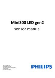
3.2.5 Zones<br />
By using the Zones option and entering a value for the Border Zones you're able to define<br />
a working plane smaller than the room floor. Entering a value for a zone (left, right, front<br />
or back) will specify the distance between one of the walls and the working plane.<br />
The previous generated working plane calculations are now automatically spread over the<br />
reduced working plane.<br />
D<br />
A<br />
W<br />
B<br />
C<br />
A<br />
B<br />
C<br />
D<br />
W<br />
= border zone left<br />
= border zone right<br />
= border zone front<br />
= border zone back<br />
= working plane<br />
<strong>Calculux</strong><br />
- 3.4 -<br />
<strong>Indoor</strong>
Chapter 3 Background Information<br />
3.2.6 Room Grids<br />
To perform lighting calculations <strong>Calculux</strong> uses grids. A grid is a set of points in a 2<br />
dimensional plane, at which the lighting calculations will be carried out. A grid must<br />
always be rectangular in shape and can be in any plane in space (horizontal, vertical or<br />
sloping).<br />
The size, position and the number of grid points can be specified by the user. Some special<br />
plane grids on walls and working planes<br />
(= Room Grids) will automatically be generated according to a standard. A standard<br />
defines the minimum number of grid points that is used for the lighting calculations.<br />
It also defines how these grid points are divided over the application area.<br />
The following standards are available:<br />
• <strong>Calculux</strong>;<br />
• NEN;<br />
• DIN;<br />
• CIBSE.<br />
(More detailed information about (Room) grids and the grid standards can be found in<br />
chapter 'Grids'.<br />
<strong>Calculux</strong><br />
- 3.5 -<br />
<strong>Indoor</strong>
Chapter 3 Background Information<br />
3.3 Application Fields<br />
3.3.1 General<br />
In <strong>Calculux</strong> an application field is represented by a 2-Dimensional rectangular shape.<br />
Application fields can be used to graphically mark the area of interest for lighting<br />
calculations. <strong>Calculux</strong> includes a number of different applications.<br />
To differentiate between the types, they contain zero or more predefined lines and/or<br />
markings that are associated with the different applications. The outlines of the built-in<br />
sports fields have already been drawn, requiring only the name, dimensions and centre<br />
position to be entered. You can choose from:<br />
• Tennis Court;<br />
• Basketball Ground;<br />
• Volleyball Ground;<br />
• <strong>Indoor</strong> hockey Field;<br />
• Ice hockey Field;<br />
• Five-a-side football Pitch;<br />
• Handball Court;<br />
• Korfball Court;<br />
• Badminton Court;<br />
• Squash Court;<br />
• Table Tennis Table;<br />
• General Field.<br />
In <strong>Calculux</strong>, for each type of application field the default dimensions and grid settings can<br />
be entered. This allows local standards to be set, limiting the input requirements of the<br />
designer. Upon selection, <strong>Calculux</strong> automatically draws the application field using the<br />
default values. <strong>Calculux</strong> also generates a grid and a surface illuminance calculation on this<br />
grid. You are then free to change the dimensions, if necessary, to suit your personal design<br />
requirements.<br />
The general application field is an empty rectangular field. It can be used when you wish to<br />
perform calculations for an application not included in the above list. A general field<br />
operates like any other application field. You can connect a grid to a general field, ensuring<br />
that any changes made to the field parameters automatically change the grid parameters.<br />
<strong>Calculux</strong><br />
- 3.6 -<br />
<strong>Indoor</strong>
Chapter 3 Background Information<br />
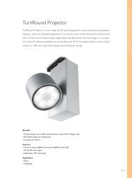
The following figure shows a basketball ground (dimensions 15 x 28 m.) with a calculation<br />
grid (grid spacing is 2m.) connected to it.<br />
Y<br />
0<br />
0<br />
X<br />
3.3.2 Connections with calculation Grids<br />
A calculation grid usually lies within an application field. <strong>Calculux</strong> enables you to connect<br />
a grid to an application field, ensuring that any changes made to the field parameters<br />
automatically change the grid parameters. You can set a calculation grid for each<br />
application field.<br />
For an example demonstrating this feature see chapter 'Grids', section 'Grid Coupling'.<br />
<strong>Calculux</strong><br />
- 3.7 -<br />
<strong>Indoor</strong>
Chapter 3 Background Information<br />
3.4 Luminaire Photometric Data<br />
<strong>Calculux</strong> can retrieve luminaire photometric data from two different sources:<br />
• A luminaire database;<br />
• A specially formatted ASCII data file.<br />
3.4.1 Luminaire Database<br />
The luminaire database is supplied with <strong>Calculux</strong> and contains a wide range of luminaires<br />
from your supplier.<br />
The luminaire database, of which you want to select your project luminaires, can be<br />
selected in the Select Database dialogue box.<br />
When a database is selected, luminaire types for a particular application area can be<br />
selected in the Application Area dialogue box. For each luminaire, details about housing,<br />
light distributors, colour, lamps and luminous flux intensity are presented on screen in a<br />
logical, step-by-step way so that choosing a suitable luminaire for an application is easy.<br />
The default luminaire database and directory in which the luminaire database is stored is set<br />
in the Database tab of the Environment Options dialogue box (Options menu). If you wish to<br />
extend the range of luminaires you can save more than one database in this directory.<br />
3.4.2 ASCII data file<br />
<strong>Calculux</strong> is supplied with an extensive <strong>Philips</strong> luminaire database.<br />
New <strong>Philips</strong> luminaires that are not yet available in the database are sometimes supplied in<br />
specially formatted ASCII data file, the PHILips LUMinaires data format (PHILLUM).<br />
Apart from the <strong>Philips</strong> database and the PHILLUM format, <strong>Calculux</strong> allows you to use<br />
photometric data from other suppliers.<br />
The following other well known formats can be used in <strong>Calculux</strong>:<br />
• CIBSE/TM14;<br />
• EULUMDAT;<br />
• IES;<br />
• LTLI.<br />
Luminaire files are stored in the default directory. You can set the location of the default<br />
directory in the Directories tab of the Environment Options dialogue box (Options menu).<br />
(The interpretation of the above luminaire formats can differ. You should pay attention<br />
when using them.<br />
<strong>Calculux</strong><br />
- 3.8 -<br />
<strong>Indoor</strong>
Chapter 3 Background Information<br />
3.5 Luminaire Positioning and Orientation<br />
3.5.1 Luminaire Positioning<br />
XYZ-coordinates<br />
To position a luminaire, <strong>Calculux</strong> requires<br />
the use of the (three dimensional) coordinate<br />
system XYZ. The X L<br />
Y L<br />
Z L<br />
coordinates position<br />
the centre of the luminaire in relation to the<br />
origin of the coordinate system.<br />
The arrow in the following illustration<br />
indicates the centre of the light emitting area<br />
of the luminaire and represents the main axis<br />
of that particular luminaire.<br />
Z L<br />
Z<br />
X L<br />
270˚<br />
90˚<br />
0˚<br />
Y L<br />
180˚<br />
Y<br />
X<br />
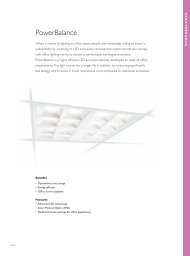
C-γ coordinate system<br />
Each luminaire is given its own luminous intensity coordinate system,<br />
in order to provide information on its luminous flux distribution.<br />
In general, the C-γ coordinate system is used. To create the required luminous flux<br />
distribution in your design you'll need to define a new orientation for the luminaire.<br />
This is done by rotating and/or tilting the luminaire in relation to its (local) coordinate<br />
system.<br />
For indoor fluorescent luminaires the longitudinal axis of the lamp is called the<br />
C=90°/C=270° axis. The lateral axis of the lamp (perpendicular to the longitudinal axis) is<br />
called the C=0°/C=180° axis. For luminaires with an unusual shape, such as those used in<br />
outdoor applications, the mounting bracket is usually regarded as a reference which<br />
corresponds to the C=270° axis. The vertical axis of the lamp is normally called the<br />
γ=0°/γ=180° axis.<br />
The following illustrations display the C-γ coordinate system for the three main luminaire<br />
types, being street, indoor and floodlighting.<br />
C=180˚ γ=180˚ C=0˚<br />
C=270˚ C=90˚<br />
C=60˚<br />
C=30˚<br />
C=180˚ γ=180˚ C=0˚<br />
C=270˚ C=90˚<br />
C=60˚<br />
C=30˚<br />
γ=0˚<br />
γ=0˚<br />
Street<br />
<strong>Indoor</strong><br />
<strong>Calculux</strong><br />
- 3.9 -<br />
<strong>Indoor</strong>
Chapter 3 Background Information<br />
C=180˚ γ=180˚ C=0˚<br />
C=270˚ C=90˚<br />
C=60˚<br />
C=30˚<br />
γ=0˚<br />
Flood<br />
3.5.2 Luminaire Orientation<br />
Aiming types<br />
To determine the orientation of a luminaire you can use either:<br />
• Aiming by defining a fixed point (XYZ);<br />
• Aiming by defining fixed angles (RBA).<br />
<strong>Calculux</strong> enables you to aim the luminaires with RBA aiming type and view the generated<br />
aiming point by switching from RBA aiming to XYZ aiming (and vice versa).<br />
XYZ aiming<br />
If XYZ aiming is used, the luminaire orientation is determined by defining its aiming<br />
point. This is the point (P) towards which the main axis (γ=0°) is directed, see figure below.<br />
The position of the aiming point P (X p<br />
, Y p<br />
, Z p<br />
) is related to the global coordinate system.<br />
• α = Rot<br />
• β = Tilt90<br />
Z<br />
Y<br />
Z L<br />
180˚<br />
90˚<br />
Y L Y P<br />
270˚ 270˚<br />
270˚<br />
0˚<br />
Z P<br />
P<br />
β<br />
α<br />
X L X P<br />
X<br />
<strong>Calculux</strong><br />
- 3.10 -<br />
<strong>Indoor</strong>
Chapter 3 Background Information<br />
RBA aiming<br />
The luminaire is aimed (orientated) by defining fixed angles for Rot (around the vertical<br />
axis), Tilt90 (around the C=0°/C=180° axis) and Tilt0 (around the C=90°/C=270° axis).<br />
Rotation (Rot)<br />
If you wish to change the angle of rotation of the luminaire about its vertical axis, you<br />
need to enter a value in degrees for the variable 'Rot'. This value can be positive or<br />
negative.<br />
For example Rot = 45°:<br />
Z<br />
γ=180˚<br />
C=270˚ C=90˚<br />
C=180˚<br />
C=0˚<br />
γ=0˚<br />
Y<br />
45˚<br />
X<br />
<strong>Calculux</strong><br />
- 3.11 -<br />
<strong>Indoor</strong>
Chapter 3 Background Information<br />
Tilt90<br />
If you wish to change the angle of rotation of a luminaire about its C=0°/C=180° axis, you<br />
need to enter a value in degrees for the variable Tilt90. This value can be positive or<br />
negative.<br />
For example Tilt90 = 30°:<br />
γ=180˚<br />
Z<br />
C=90˚<br />
C=180˚<br />
30˚<br />
C=0˚<br />
C=270˚<br />
γ=0˚<br />
Y<br />
X<br />
Tilt0<br />
If you wish to change the angle of rotation of a luminaire about its C=90°/C=270° axis,<br />
you need to enter a value in degrees for the variable Tilt0. This value can be positive or<br />
negative.<br />
For example Tilt0 = 30°:<br />
Z<br />
C=270˚<br />
γ=180˚<br />
C=0˚<br />
C=180˚<br />
C=90˚<br />
Y<br />
γ=0˚<br />
30˚<br />
X<br />
Luminaire orientation order<br />
When specifying values for RBA aiming <strong>Calculux</strong> uses the following specification order:<br />
• Rot;<br />
• Tilt90;<br />
• Tilt0.<br />
Extra attention must be paid, because the order in which the variables will be processed is<br />
of great influence on the resulting orientation.<br />
<strong>Calculux</strong><br />
- 3.12 -<br />
<strong>Indoor</strong>
Chapter 3 Background Information<br />
For example if the following sequence of processing is executed for a luminaire:<br />
• 90° rotation about the vertical axis (Rot=90°);<br />
• 90° rotation about the C=0°/C=180° axis (Tilt90=90°);<br />
• 90° rotation about the C=90°/C=270° axis (Tilt0=90°).<br />
The result of the above order of processing gives the following orientation:<br />
Z<br />
Z<br />
Z<br />
Z<br />
270˚<br />
0˚<br />
γ=180˚<br />
180˚<br />
90˚<br />
180˚<br />
270˚<br />
γ=180˚<br />
90˚<br />
0˚<br />
180˚<br />
90˚<br />
0˚<br />
γ=180˚ γ=0˚<br />
270˚<br />
γ=180˚ γ=0˚<br />
0˚<br />
90˚<br />
270˚<br />
180˚<br />
Y<br />
γ=0˚<br />
Y<br />
γ=0˚<br />
Y<br />
Y<br />
X<br />
X<br />
X<br />
X<br />
Consider this against the following order of processing:<br />
• 90° rotation about the vertical axis (Rot=90°);<br />
• 90° rotation about the C=90°/C=270° axis (Tilt0=90°);<br />
• 90° rotation about the C=0°/C=180° axis (Tilt90=90°).<br />
This will result in the following orientation:<br />
Z<br />
Z<br />
Z<br />
Z<br />
270˚<br />
γ=180˚<br />
180˚<br />
180˚<br />
γ=180˚<br />
90˚<br />
γ=180˚<br />
0˚<br />
90˚<br />
90˚<br />
0˚<br />
γ=0˚<br />
0˚<br />
90˚<br />
270˚<br />
0˚<br />
270˚<br />
180˚<br />
γ=0˚<br />
γ=180˚<br />
180˚<br />
270˚<br />
Y<br />
γ=0˚<br />
Y<br />
γ=0˚<br />
Y<br />
Y<br />
X<br />
X<br />
X<br />
X<br />
Conversion of Aiming types<br />
Conversion from RBA aiming to XYZ aiming<br />
The XYZ coordinates of the aiming points are locked on the aiming plane. Conversion<br />
from RBA-aiming to XYZ-aiming is only possible when the Tilt0 of the luminaire is 0°.<br />
This restriction is included to prevent the loss of orientation information. The XYZ<br />
coordinates are blanked out in case the luminaire has to be displayed in XYZ-aiming, and<br />
there is no intersection with the aiming plane.<br />
In the case of a modification in the aiming type when there's no intersection with the<br />
aiming plane, the point on the aiming vector, one meter from the luminaire, is chosen as<br />
the aiming point.<br />
Conversion from XYZ aiming to RBA aiming<br />
The direction from the location of the luminaire to the aiming-point is determined.<br />
This direction is expressed in a Rotation, Tilt90 and Tilt0 (Tilt0 is always 0°).<br />
<strong>Calculux</strong><br />
- 3.13 -<br />
<strong>Indoor</strong>
Chapter 3 Background Information<br />
Selecting Aiming Presentation types<br />
<strong>Calculux</strong> allows you to select either RBA aiming presentation to display the Rot, Tilt90<br />
and Tilt0 aiming angles, or XYZ aiming presentation to display the aiming points. If the<br />
selected aiming presentation is different from the used aiming type, <strong>Calculux</strong> will convert<br />
the unit for aiming into the unit as selected for the aiming presentation. In this way it is<br />
possible to view the value of the aiming angles while the used aiming type is XYZ aiming<br />
or aiming points while the used aiming type is RBA aiming.<br />
The aiming presentation of luminaires can be set in the luminaires list.<br />
Conversion from RBA aiming presentation to XYZ aiming presentation for a luminaire is<br />
only possible when Tilt0=0°. This restriction is included to prevent the loss of orientation<br />
information. When a luminaire, aimed with RBA aiming, has to be displayed in XYZ<br />
aiming and there's no intersection with the aiming plane, the XYZ coordinate values are<br />
blanked out.<br />
(Conversion of the aiming presentation type does not change the aiming type!<br />
<strong>Calculux</strong><br />
- 3.14 -<br />
<strong>Indoor</strong>
Chapter 3 Background Information<br />
Aiming offset (Floodlights)<br />
For some asymmetric flood lighting<br />
luminaires an aiming offset is given and<br />
stored in the database.<br />
It can be viewed in the project luminaire<br />
details dimensions tab. The aiming offset is<br />
usually equal to the angle of the maximum<br />
intensity in the C=90° plane.<br />
α<br />
For a luminaire with an aiming offset the<br />
photometric data is treated with respect to<br />
the aiming of the luminaire as if the<br />
maximum intensity is at C=0° and γ=0°.<br />
Aiming the above luminaire with an aiming<br />
offset of<br />
α degrees at Rot=0° and Tilt90=0° gives the<br />
orientation displayed next.<br />
α<br />
α<br />
To ensure that the front glass of the<br />
luminaire is horizontal, the aiming should be<br />
Rot=0° and Tilt90=α°.<br />
α<br />
<strong>Calculux</strong><br />
- 3.15 -<br />
<strong>Indoor</strong>
Chapter 3 Background Information<br />
3.5.3 Number of luminaires per position (Luminaire Quantity)<br />
Normally there will be one luminaire at each luminaire position. In some special cases it<br />
can be very useful to use a different number of luminaires, for instance;<br />
• When a group of 5 luminaires (floodlights) with the same aiming point is situated on a<br />
pole, these luminaires can technically be regarded as one luminaire. In this case you can<br />
enter a luminaire quantity of 5.<br />
• When in a block arrangement at one particular luminaire position no luminaire can be<br />
installed.<br />
Example:<br />
Luminaire Quantity of position<br />
(20,5)=0.<br />
Z<br />
Y<br />
5<br />
10<br />
0˚ 0˚<br />
0˚<br />
0˚ 0˚<br />
0˚<br />
0˚ 0˚<br />
0˚<br />
0˚ 0˚<br />
0˚<br />
0˚<br />
5 10 15 20<br />
X<br />
<strong>Calculux</strong><br />
- 3.16 -<br />
<strong>Indoor</strong>
Chapter 3 Background Information<br />
3.6 Individual Luminaires<br />
3.6.1 General<br />
<strong>Calculux</strong> allows you to position luminaires individually as well as in groups.<br />
The definition of individual luminaires is done in the 'Individual Luminaires' dialogue<br />
box. This dialogue box contains two tab pages.<br />
In the Luminaires tab you can select the project luminaires which have been defined in the<br />
Project Luminaires dialogue box and set or change luminaire parameters. In the View tab<br />
you can view the luminaires graphically.<br />
3.6.2 Luminaire Definition<br />
In the Luminaires tab you can define and position individual luminaires.<br />
For the definition of a new luminaire the following parameters, if applicable, have to be<br />
set:<br />
• Project Luminaire Type;<br />
• Aiming Presentation;<br />
• Switching Modes.<br />
When the above parameters have been set the luminaire(s) can be added to the luminaire list<br />
by clicking on the 'New' button.<br />
Project Luminaire Type<br />
If a project contains two or more luminaire types you will need to select the required<br />
luminaire type. For details about a project luminaire you can click on the 'Details' button.<br />
Aiming Presentation<br />
With this parameter you can set the aiming presentation of all luminaires in the luminaire<br />
list. Choose from either RBA or XYZ, aiming angles or aiming points.<br />
Switching Modes<br />
If switching modes are used, you can select which switching mode(s) will be appied to all<br />
new created luminaires in the luminaire list.<br />
Luminaire List<br />
The luminaire list contains information about the individually placed luminaires used in<br />
the project. You can view, set, edit, copy or delete information of project luminaires. In the<br />
luminaire list the following luminaire information, if applicable, can be set:<br />
Luminaire Type<br />
If a project contains more luminaires, and afterwards a different luminaire type is required,<br />
you can click on the down arrow in the project luminaire type box and make your<br />
selection.<br />
Luminaire Quantity<br />
With this parameter you can set the number of identical luminaires at a luminaire position<br />
(see also chapter 'Luminaire Position and Orientation'; section 'Luminaire Quantity').<br />
<strong>Calculux</strong><br />
- 3.17 -<br />
<strong>Indoor</strong>
Chapter 3 Background Information<br />
Luminaire Position (POS X, POS Y and POS Z)<br />
Use these parameters to enter the XYZ coordinates of the centre of the luminaire in<br />
relation to the origin of the coordinate system.<br />
Luminaire Orientation (Aiming Type)<br />
Depending on the defined Aiming Type and selected Aiming Presentation you can set<br />
and/or view the RBA angles (Rot / Tilt90 / Tilt0) or the XYZ coordinates Aim. Pnt. X /<br />
Aim. Pnt. Y / Aim. Pnt. Z.<br />
(By pressing on the 'To XYZ' or 'To RBA' button you can convert the aiming type of<br />
selected luminaires from RBA aiming to XYZ aiming or vice versa.<br />
Symmetry (Sym.)<br />
If you want to apply symmetry, you can set the symmetry type for the luminaires.<br />
The Sym. column shows which type of Symmetry is used ('NONE', 'X', 'Y' or 'XY'). If X- or<br />
XY symmetry is used, for the X-origin the X coordinate of the YZ plane has to be entered.<br />
If Y- or XY symmetry is used, for the Y-origin column the Y coordinate of the XZ plane<br />
has to be entered.<br />
For more information about symmetry, see chapter 'Symmetry'.<br />
Switching Modes (1, 2, ...)<br />
If switching modes are applied, you can view or set which of the available switching modes<br />
are activated for each luminaire.<br />
Each column number is identical to the switching mode sequence number in the<br />
'Switching Mode' list box. The switching modes columns will only be displayed if more<br />
then one switching mode(s) exist.<br />
Light Regulation Factors (%)<br />
If light regulation factors are applied, you can set and/or view the value of the light<br />
regulation factor (0 - 100%) for each luminaire.<br />
3.6.3 View<br />
The View tab displays the luminaires in the arrangement graphically.<br />
<strong>Calculux</strong><br />
- 3.18 -<br />
<strong>Indoor</strong>
Chapter 3 Background Information<br />
3.7 Luminaire Arrangements<br />
3.7.1 General<br />
<strong>Calculux</strong> allows you to position luminaires individually as well as in groups. A number of<br />
luminaires defined as a group is called an luminaire arrangement.<br />
To simplify the definition of an arrangement, <strong>Calculux</strong> contains the 'Arranged Luminaires'<br />
option.<br />
The luminaires in an arrangement are positioned and aimed according to the arrangement<br />
rule and are stored under the 'arrangement name'.<br />
The arrangement generation rules relate to all arrangements (where applicable) and are<br />
explained here for the following arrangements:<br />
• Room Block;<br />
• Block;<br />
• Polar;<br />
• Line;<br />
• Free.<br />
(When you define an arrangement, the arrangement must fit in the room.<br />
A Free arrangement is a special kind of arrangement allowing the luminaires to be<br />
positioned individually. The only thing they share is a common arrangement name.<br />
In the case of a Block, Line, Polar or Room Block arrangement, the luminaire positions are<br />
controlled by the arrangement rule. The other attributes can be set individually.<br />
In general, for each arrangement the following luminaire attributes<br />
(if applicable) must be set:<br />
• Project luminaire Type;<br />
• Position of the arrangement;<br />
• Orientation of the arrangement (Aiming);<br />
• Symmetry type and relevant symmetry origin;<br />
• Number of Same (luminaires per position);<br />
• Switching mode(s).<br />
To simplify the definition of the attributes, the arrangements dialogue box is split into the<br />
following four tab pages.<br />
Arrangement Definition<br />
In the Arrangement Definition tab you can define the name and position of the<br />
arrangement in relation to the XYZ coordinate system. Where applicable you can set the<br />
orientation<br />
(= aiming) of the arrangement.<br />
(For a 'Room Block arrangement' only the orientation of the luminaires can be set.<br />
<strong>Calculux</strong><br />
- 3.19 -<br />
<strong>Indoor</strong>
Chapter 3 Background Information<br />
Luminaire Definition<br />
In the Luminaire Definition tab you can define the default settings for all luminaires in<br />
the arrangement. The settings are used for the generation of the luminaires at the position<br />
as set in the Arrangement Definition tab and determine the initial generation of the<br />
luminaire list.<br />
The default settings can be changed at any time by making changes to the luminaire<br />
definitions. By using the Apply buttons you ensure the setting changes are carried out for<br />
all luminaires in the luminaire list.<br />
Warning:<br />
Take care when you have created an arrangement with a unique aiming pattern. When you<br />
click on the Aiming Apply button the settings will be applied to all the luminaires in the<br />
luminaire list and the unique aiming pattern will be lost. If you don't want this and it does<br />
happen, click on the Cancel button and the action will be undone. Note that the Cancel<br />
facility is effective in any of the tabs of the arrangement dialogue box.<br />
Luminaire List<br />
In the Luminaire List tab you can view the attributes of each luminaire in the arrangement.<br />
All attributes, except the luminaire positions can be changed. For a Free arrangement, it's<br />
possible to change the position of the luminaires as well.<br />
View<br />
The View tab displays the luminaires in the arrangement graphically.<br />
3.7.2 Room Block Arrangement<br />
A Room Block arrangement is a special type of Block arrangement where the luminaires<br />
are arranged in a rectangular room.<br />
Arrangement Definition<br />
There are two ways to define a Room Block arrangement:<br />
a) You can create a Room Block arrangement using the UF Method (see also chapter<br />
'Room'; section 'UF Method').<br />
The following parameters have to be set:<br />
• Luminaire Type;<br />
• Orientation of the luminaires;<br />
• Name of the arrangement.<br />
If you press the Generate button a regular luminaire pattern will automatically be<br />
generated at the ceiling of the room. The number of generated luminaires depends on the<br />
value you've entered in the 'Required Illuminance Level' field of the 'Room' dialogue box.<br />
The number of luminaires will only be calculated if the information for<br />
the UF Method is included in the Data base.<br />
(If required you can change the value of the 'Number of Luminaires needed'. If the value<br />
fulfils the max. spacing to lighting ratio given in the database, Calulux will perform light<br />
calculations using the value in the 'Number of Luminares needed' field.<br />
<strong>Calculux</strong><br />
- 3.20 -<br />
<strong>Indoor</strong>
Chapter 3 Background Information<br />
b) You can create a Room Block arrangement by defining the number of luminaires and<br />
the spacing between the luminaires.<br />
In this case the following parameters have to be set:<br />
• Luminaire Type;<br />
• Orientation of the luminaires;<br />
• Name of the arrangement;<br />
• Number of luminaires in X and Y direction;<br />
• Spacing between the luminaires in X and Y direction;<br />
• Position of the arrangement.<br />
When the Room Block arrangement has been defined, depending on the position of the<br />
arrangement a number of ways of updating are possible:<br />
Using<br />
Regular button<br />
Centre button<br />
Updates<br />
Position X, Y, Z<br />
Position X, Y, Z<br />
Example:<br />
For a Room Block arrangement with default luminaire orientation, the following definition is<br />
given:<br />
Dimensions of the 'room' = 16.0, 10.0, 6.0<br />
Position of the 'Front Bottom<br />
Left' corner of the room = 1.0, 2.0<br />
Number in X = 3<br />
Number in Y = 2<br />
X Spacing = 6.0<br />
Y Spacing = 5.0<br />
Position (of arrangement) = 3.0, 4.0, 6.0 (=P)<br />
This creates the following arrangement:<br />
6<br />
Z<br />
1 3<br />
2 4<br />
0˚ 180˚ 0˚ 180˚<br />
0˚ 180˚<br />
Y<br />
0˚ 180˚<br />
0˚ 180˚<br />
0˚ 180˚<br />
17<br />
X<br />
<strong>Calculux</strong><br />
- 3.21 -<br />
<strong>Indoor</strong>
Chapter 3 Background Information<br />
Now luminaire rotation and Tilt is applied to the previous figure:<br />
Rotation = 90°<br />
Tilt90 = 0°<br />
Tilt0 = 0°<br />
Z<br />
180˚ 0˚<br />
Y<br />
6<br />
180˚ 0˚<br />
180˚ 0˚<br />
180˚ 0˚<br />
180˚ 0˚<br />
2<br />
180˚ 0˚<br />
1<br />
17 X<br />
Rotation = 0°<br />
Tilt90 = 45°<br />
Tilt0 = 0°<br />
Z<br />
90˚<br />
90˚<br />
90˚<br />
6<br />
90˚<br />
90˚<br />
90˚<br />
2<br />
1<br />
17 X<br />
(The warning 'Arrangement does not fit in the room' will appear when the luminaires tilt,<br />
positions the luminaires outside the room. In this case the Z-position of the luminaires<br />
should be changed.<br />
Luminaire Definition<br />
For the definition of the luminaires, the following parameters can be set:<br />
• Symmetry;<br />
• Number of Same;<br />
• Switching Modes.<br />
(For each parameter there is a separate Apply button. When settings are changed you can<br />
click on the Apply button to carry out the settings for all luminaires in the luminaire list.<br />
Selection of different parameter settings for individual luminaires of the arrangement is<br />
done in the luminaire list.<br />
<strong>Calculux</strong><br />
- 3.22 -<br />
<strong>Indoor</strong>
Chapter 3 Background Information<br />
Symmetry<br />
If you want to apply symmetry, you can set the default symmetry type for the luminaires in<br />
the arrangement.<br />
Number of Same<br />
With this parameter you can set the number of identical luminaires at a luminaire position<br />
(see also chapter 'Luminaire Position and Orientation'; section 'Luminaire Quantity').<br />
Switching Modes<br />
If switching modes are used, you can select which switching mode you want to apply to the<br />
luminaires in the arrangement.<br />
3.7.3 Block Arrangement<br />
In a Block arrangement the luminaires are arranged in a rectangular shape.<br />
Arrangement Definition<br />
For the definition of a Block arrangement, the following parameters have to be set:<br />
• Name of the arrangement;<br />
• Position of the arrangement;<br />
• Orientation of the arrangement;<br />
• Number of luminaires in AB and AC direction;<br />
• Spacing between the luminaires in AB and AC direction.<br />
(To simplify the definition of a Block arrangement you should first define a Block<br />
arrangement without orientation (rotation or tilt) and afterwards<br />
(if applicable) apply rotation and/or tilt.<br />
Example:<br />
For the definition of a Block arrangement without rotation or tilt, set:<br />
Position A The block position.<br />
P<br />
Reference point P is the position of the bottom left luminaire in the<br />
arrangement (if no rotation and tilt is applied).<br />
N AB<br />
The number of luminaires in AB direction (if the block is not rotated,<br />
AB is parallel to the XZ-plane).<br />
N AC<br />
The number of luminaires in AC direction (if the block is not rotated,<br />
AC is parallel to the YZ-plane).<br />
Spacing AB<br />
The distance between the luminaires in the AB direction (D1).<br />
Spacing AC<br />
The distance between the luminaires in the AC direction (D2).<br />
<strong>Calculux</strong><br />
- 3.23 -<br />
<strong>Indoor</strong>
Chapter 3 Background Information<br />
P = 4.0, 3.0, 2.0<br />
N AB<br />
= 3<br />
N AC<br />
= 2<br />
Spacing AB<br />
= 2.0 m<br />
Spacing AC<br />
= 6.0 m<br />
2<br />
Z<br />
3<br />
D2<br />
0˚<br />
P<br />
A<br />
0˚<br />
0˚<br />
0˚<br />
B<br />
Y<br />
C<br />
0˚<br />
0˚<br />
4<br />
D1<br />
X<br />
Now the Block arrangement is generated, you can apply rotation and/or tilt.<br />
For instance:<br />
Rotation = 30°:<br />
The Block arrangement is rotated 30° anti<br />
clockwise around the V-axis which passes<br />
through P and is parallel to the Z-axis.<br />
Z<br />
V<br />
0˚<br />
C<br />
0˚<br />
Y<br />
0˚<br />
2<br />
3<br />
0˚<br />
P<br />
A<br />
0˚<br />
0˚<br />
B<br />
D2<br />
4<br />
30˚<br />
D1<br />
X<br />
(In a Block Arrangement the luminaires are oriented in relation to the XYZ coordinate<br />
system (= global coordinate system). Therefore, only the arrangement is rotated, the<br />
orientation of the individual luminaires is not changed.<br />
Tilt90 = 30°:<br />
The block is rotated 30° around the AC-axis<br />
towards the positive Z-axis.<br />
Z<br />
2<br />
3<br />
D2<br />
4<br />
0˚<br />
A C<br />
P<br />
D1<br />
0˚<br />
30˚<br />
0˚<br />
0˚<br />
Y<br />
0˚<br />
0˚<br />
X<br />
<strong>Calculux</strong><br />
- 3.24 -<br />
<strong>Indoor</strong>
Chapter 3 Background Information<br />
Tilt0 = -30°:<br />
The block is rotated 30° around the AB-axis<br />
towards the negative Z-axis.<br />
Z<br />
D2<br />
0˚<br />
C<br />
0˚<br />
0˚<br />
Y<br />
2<br />
3<br />
0˚<br />
P<br />
A<br />
0˚<br />
0˚<br />
B<br />
4<br />
30˚<br />
D1<br />
X<br />
(The block Rotation, Tilt90 and Tilt0 are equivalent to the luminaire Rotation, Tilt90 and<br />
Tilt0 in the way they operate, but they are in fact separate orientations. The block<br />
orientation is set in the 'Arrangement Definition' tab, and controls the luminaire<br />
positions, while the luminaire orientation (= 'Aiming') is set in the 'Luminaire Definition'<br />
tab. If you want to have the luminaires orientated in the same direction as the<br />
arrangement, the angles of the arrangement and luminaire orientation have to be the same.<br />
Luminaire Definition<br />
For the definition of the luminaires, the following parameters can be set:<br />
• Project Luminaire Type;<br />
• Aiming Type;<br />
• Symmetry;<br />
• Number of Same;<br />
• Switching Modes.<br />
(For each parameter there is a separate Apply button. When settings are changed you can<br />
click on the Apply button to carry out the settings for all luminaires in the luminaire list.<br />
Selection of different parameter settings for individual luminaires of the arrangement is<br />
done in the luminaire list.<br />
Project Luminaire Type<br />
If a project contains two or more luminaire types, you need to select the required<br />
luminaire type. If afterwards a different luminaire type is needed, you can click on the<br />
down arrow in the Project Luminaire Type box and make your selection.<br />
Aiming Type<br />
With this parameter you can set the default aiming type (choose from either RBA or XYZ),<br />
aiming angles or aiming points for the luminaires in the arrangement.<br />
Symmetry<br />
If you want to apply symmetry, you can set the default symmetry type for the luminaires in<br />
the arrangement.<br />
Number of Same<br />
With this parameter you can set the number of identical luminaires at a luminaire position<br />
(see also chapter 'Luminaire Position and Orientation'; section 'Luminaire Quantity').<br />
<strong>Calculux</strong><br />
- 3.25 -<br />
<strong>Indoor</strong>
Chapter 3 Background Information<br />
Switching Modes<br />
If switching modes are used, you can select which switching mode you want to apply to the<br />
luminaires in the arrangement.<br />
3.7.4 Polar Arrangement<br />
In a Polar arrangement the luminaires are arranged in one or more concentric arcs.<br />
Arrangement Definition<br />
For the definition of a Polar arrangement, the following parameters have to be set:<br />
• Name of the arrangement;<br />
• Centre position of the arrangement;<br />
• Orientation of the arrangement (orientation of the plane);<br />
• Number of luminaires per arc;<br />
• Spacing between the luminaires on an arc;<br />
• Length of an arc;<br />
• Number of concentric arcs;<br />
• Distance between two adjacent arcs;<br />
• Radius of the arc that is nearest to the centre.<br />
When the Polar arrangement has been entered, a number of ways of updating are possible:<br />
Changing<br />
Luminaires per Arc<br />
Spacing along Arc<br />
Length of the Arc<br />
Updates<br />
Spacing along Arc<br />
Length of an Arc (Total Arc)<br />
Spacing along Arc<br />
(To simplify the definition of a Polar arrangement you can best first define an arrangement<br />
without orientation (rotation or tilt) and afterwards (if applicable) apply rotation and/or<br />
tilt.<br />
Example:<br />
For a Polar arrangement without rotation or tilt, the following definition is given:<br />
Centre Position (P) = (10.0, 6.0, 2.0)<br />
Luminaires per Arc = 5<br />
Spacing along Arc = 45°<br />
Total Arc = 180°<br />
# of Concentric Arcs = 2<br />
Distance between Arcs (d) = 5.0 m<br />
Radius of First Arc (r) = 4.0 m<br />
<strong>Calculux</strong><br />
- 3.26 -<br />
<strong>Indoor</strong>
Chapter 3 Background Information<br />
Which results in the following<br />
arrangement:<br />
Z<br />
Y<br />
90˚<br />
2<br />
6<br />
90˚<br />
90˚<br />
d r P<br />
90˚<br />
90˚<br />
90˚<br />
90˚ 90˚<br />
90˚<br />
90˚<br />
10<br />
90˚<br />
X<br />
Now rotation and tilt is applied to the previously defined Polar arrangement.<br />
For instance:<br />
Rotation = 30°:<br />
Z<br />
90˚<br />
Y<br />
90˚<br />
6<br />
2<br />
90˚ 90˚<br />
90˚ 90˚ 90˚<br />
90˚<br />
90˚<br />
90˚<br />
90˚<br />
P<br />
30˚<br />
10 X<br />
The arrangement is rotated 30° counter clockwise around the V-axis which passes through<br />
P and is parallel to the Z-axis.<br />
(In a Polar arrangement, the orientation of the luminaires is related to the centre point (P)<br />
of the arrangement. So every time you change the orientation of the arrangement, the<br />
orientation of the luminaire will change too.<br />
Tilt90 = 30°:<br />
Z<br />
Y<br />
2<br />
6<br />
90˚ 90˚ 90˚<br />
90˚<br />
A'<br />
90˚ 90˚<br />
P<br />
90˚ 90˚<br />
30˚<br />
C'<br />
90˚ 90˚<br />
10 X<br />
<strong>Calculux</strong><br />
- 3.27 -<br />
<strong>Indoor</strong>
Chapter 3 Background Information<br />
The arrangement is rotated 30° around the A'C'-axis towards the positive Z-axis.<br />
If no rotation is applied, A'C' is parallel to the YZ-plane.<br />
Tilt0 = -30°:<br />
Z<br />
2<br />
A'<br />
6<br />
90˚<br />
Y<br />
90˚<br />
90˚ 90˚<br />
P ref<br />
A'<br />
90˚ 90˚ 90˚<br />
90˚ 90˚<br />
90˚ 90˚<br />
30˚<br />
10<br />
B'<br />
X<br />
The arrangement is rotated 30° around the A'B'-axis towards the negative Z-axis.<br />
If no rotation is applied, A'B' is parallel to the XZ-plane.<br />
Luminaire Definition<br />
For the definition of the luminaires, the following parameters can be set:<br />
• Project Luminaire Type;<br />
• Aiming Type;<br />
• Symmetry;<br />
• Number of Same;<br />
• Switching Modes.<br />
(For each parameter there is a separate Apply button. When settings are changed you can<br />
click on the Apply button to carry out the settings for all luminaires in the luminaire list.<br />
Selection of different parameter settings for individual luminaires of the arrangement is<br />
done in the luminaire list.<br />
Project Luminaire Type<br />
If a project contains two or more luminaire types, you need to select the required<br />
luminaire type. If afterwards a different luminaire type is needed, you can click on the<br />
down arrow in the Project Luminaire Type box and make your selection.<br />
Aiming Type<br />
With this parameter you can set the default Aiming Type (choose from either RBA or<br />
XYZ), Aiming Angles or Aiming Points for the luminaires in the arrangement.<br />
Example:<br />
• When the luminaire orientation is set to<br />
Rot = 90°<br />
Tilt90 = 0°<br />
Tilt0 = 0°<br />
<strong>Calculux</strong><br />
- 3.28 -<br />
<strong>Indoor</strong>
90˚<br />
90˚<br />
Chapter 3 Background Information<br />
This results in the following arrangement:<br />
Z<br />
2<br />
6<br />
90˚<br />
90˚<br />
Y<br />
90˚<br />
90˚<br />
90˚<br />
90˚<br />
90˚<br />
90˚<br />
90˚<br />
90˚<br />
P<br />
90˚<br />
90˚<br />
10<br />
X<br />
• When the luminaire orientation is set to<br />
Rot = 90°<br />
Tilt90 = 45°<br />
Tilt0 = 0°<br />
The following arrangement will be created:<br />
Z<br />
Y<br />
90˚<br />
2<br />
6<br />
90˚<br />
90˚<br />
90˚<br />
90˚<br />
90˚<br />
P<br />
90˚<br />
90˚<br />
10<br />
X<br />
Symmetry<br />
If you want to apply symmetry, you can set the default symmetry type for the luminaires in<br />
the arrangement.<br />
Number of Same<br />
With this parameter you can set the number of identical luminaires at a luminaire position<br />
(see also chapter 'Luminaire Position and Orientation'; section 'Luminaire Quantity').<br />
Switching Modes<br />
If switching modes are used, you can select which switching mode you want to apply to the<br />
luminaires in the arrangement.<br />
<strong>Calculux</strong><br />
- 3.29 -<br />
<strong>Indoor</strong>
Chapter 3 Background Information<br />
3.7.5 Line Arrangement<br />
In a Line arrangement the luminaires will be arranged in a line.<br />
Arrangement Definition<br />
For the definition of a Line arrangement, the following parameters have to be set:<br />
• Name of the arrangement;<br />
• First and last point of the line;<br />
• Number of luminaires in the line;<br />
• Spacing between the luminaires.<br />
(When the line coordinates have been entered, the line orientation is automatically set by<br />
the program. Any subsequent alterations to the line coordinates update the orientation.<br />
Example:<br />
A = First point (= reference point).<br />
The reference point is the position of<br />
the first luminaire in the arrangement.<br />
B = Last point<br />
α = Rotation<br />
β = Tilt90<br />
9.5<br />
2<br />
Z<br />
A<br />
D<br />
2 10<br />
β<br />
B<br />
Y<br />
2<br />
α<br />
8<br />
X<br />
The angle α corresponds with the Rotation of the Line arrangement.<br />
The angle β corresponds with the Tilt90 of the Line arrangement.<br />
When the Line arrangement has been entered, several ways of updating are possible:<br />
Changing<br />
First point<br />
Spacing<br />
Number of Luminaires<br />
Last point<br />
Orientation<br />
Updates<br />
Last point<br />
Last point<br />
Spacing<br />
Spacing and Orientation<br />
Last point<br />
The following Line arrangements have been created to demonstrate the different ways of<br />
defining a Line arrangement.<br />
The Line arrangement below has the following settings:<br />
First point = 1.0, 1.0, 5.0<br />
Last point = 1.0, 6.0, 5.0<br />
Number of Luminaires = 3<br />
Spacing = 2.5<br />
<strong>Calculux</strong><br />
- 3.30 -<br />
<strong>Indoor</strong>
Chapter 3 Background Information<br />
This will create the following line orientation automatically:<br />
Rot = 90°<br />
Tilt90 = 0°<br />
The luminaire orientation uses the default<br />
settings which are set to:<br />
Rot = 0°<br />
Tilt90 = 0°<br />
Tilt0 = 0°<br />
Z<br />
270˚<br />
5 A B<br />
0˚<br />
2.5<br />
270˚<br />
0˚<br />
270˚<br />
0˚<br />
Y<br />
1<br />
α=90˚<br />
1<br />
X<br />
• From the previous illustration, the luminaire orientation is now set to:<br />
a) Rot = 0°<br />
Tilt90 = 45° (rotation of 45° around C=0°...C=180° axis)<br />
Tilt0 = 0°<br />
Which results in the following arrangement:<br />
Z<br />
1<br />
1<br />
A<br />
0˚<br />
45˚<br />
2.5<br />
0˚<br />
6<br />
B<br />
0˚<br />
5 5<br />
α=90˚<br />
A2 B2<br />
Y<br />
X<br />
<strong>Calculux</strong><br />
- 3.31 -<br />
<strong>Indoor</strong>
Chapter 3 Background Information<br />
b) Rot = 90° (rotation of 90°C around the vertical axis)<br />
Tilt90 = 45° (rotation of 45° around C=0°...C=180° axis)<br />
Tilt0 = 0°<br />
Which results in the following arrangement:<br />
Z<br />
A<br />
2.5<br />
180˚ 0˚<br />
B<br />
180˚ 0˚<br />
1<br />
180˚ 0˚<br />
90˚<br />
45˚<br />
5 5<br />
1<br />
6<br />
α=90˚<br />
A2 B2<br />
Y<br />
X<br />
• If a line arrangement is given the following settings:<br />
First point = 2.0, 2.0, 2.0<br />
Last point = 8.0,10.0, 9.5<br />
Number of Luminaires = 3<br />
Spacing<br />
= 6.25 m (calculated automatically by the program)<br />
This will create the following line orientation automatically:<br />
Rot = 53.1° (α)<br />
Tilt90 = 36.9° (β)<br />
When the luminaire orientation (Aiming Type) is set to:<br />
Rot = 0°<br />
Tilt90 = 45° (rotation of 45° around C=0°...C=0° axis)<br />
Tilt0 = 0°<br />
The following arrangement will be created:<br />
Z<br />
9.5<br />
2<br />
0˚<br />
0˚<br />
A B<br />
2 10<br />
β<br />
0˚<br />
Y<br />
2<br />
α<br />
8<br />
X<br />
<strong>Calculux</strong><br />
- 3.32 -<br />
<strong>Indoor</strong>
Chapter 3 Background Information<br />
The luminaire orientation in the above<br />
arrangement can now be set with the same<br />
values as the line orientation (Rot = 53.1°;<br />
Tilt90 = 36.9°), so that the luminaire<br />
orientation is 'in line' with the line<br />
orientation.<br />
9.5<br />
2<br />
Z<br />
90˚<br />
A B<br />
90˚<br />
β<br />
2 10<br />
90˚<br />
Y<br />
2<br />
α<br />
α<br />
8<br />
X<br />
Luminaire Definition<br />
For the definition of the luminaires, the following parameters can be set:<br />
• Project Luminaire Type;<br />
• Aiming Type;<br />
• Symmetry;<br />
• Number of Same;<br />
• Switching Modes.<br />
(For each parameter there is a separate Apply button. When settings are changed you can<br />
click on the Apply button to carry out the settings for all luminaires in the luminaire list.<br />
Selection of different parameter settings for individual luminaires of the arrangement is<br />
done in the luminaire list.<br />
Project Luminaire Type<br />
If a project contains two or more luminaire types, you need to select the required<br />
luminaire type. If afterwards a different luminaire type is needed, you can click on the<br />
down arrow in the Project Luminaire Type box and make your selection.<br />
Aiming Type<br />
With this parameter you can set the default aiming type (choose from either RBA or XYZ),<br />
aiming angles or aiming points for the luminaires in the arrangement.<br />
Symmetry<br />
If you want to apply symmetry, you can set the default symmetry type for the luminaires in<br />
the arrangement.<br />
Number of Same<br />
With this parameter you can set the number of identical luminaires at a luminaire position<br />
(see also chapter 'Luminaire Position and Orientation'; section 'Luminaire Quantity').<br />
Switching Modes<br />
If switching modes are used, you can select which switching mode you want to apply to the<br />
luminaires in the arrangement.<br />
<strong>Calculux</strong><br />
- 3.33 -<br />
<strong>Indoor</strong>
Chapter 3 Background Information<br />
3.7.6 Free Arrangement<br />
A Free arrangement is a special arrangement type, where the number of luminaires and<br />
their position is not defined by an arrangement rule.<br />
Arrangement Definition<br />
For the definition of a Free Arrangement only the name of the arrangement has to be<br />
specified. There is no arrangement rule for defining the number of luminaires and their<br />
positions.<br />
(The definition of the luminaires and their positions is done in the same way as individual<br />
luminaires (see chapter 'Individual Luminaires').<br />
Luminaire Definition<br />
For the definition of the luminaires, the following parameters can be set:<br />
• Project Luminaire Type;<br />
• Aiming Type;<br />
• Symmetry;<br />
• Number of Same;<br />
• Switching Modes.<br />
(For each parameter there is a separate Apply button. When settings are changed you can<br />
click on the Apply button to carry out the settings for all luminaires in the luminaire list.<br />
Selection of different parameter settings for individual luminaires of the arrangement is<br />
done in the luminaire list.<br />
Project Luminaire Type<br />
If a project contains two or more luminaire types, you need to select the required<br />
luminaire type. If afterwards a different luminaire type is needed, you can click on the<br />
down arrow in the Project Luminaire Type box and make your selection.<br />
Aiming Type<br />
With this parameter you can set the default aiming type (choose from either RBA or XYZ),<br />
aiming angles or aiming points for the luminaires in the arrangement.<br />
Symmetry<br />
If you want to apply symmetry, you can set the default symmetry type for the luminaires in<br />
the arrangement.<br />
Number of Same<br />
With this parameter you can set the number of identical luminaires at a luminaire position<br />
(see also chapter 'Luminaire Position and Orientation'; section 'Luminaire Quantity').<br />
Switching Modes<br />
If switching modes are used, you can select which switching mode you want to apply to the<br />
luminaires in the arrangement.<br />
<strong>Calculux</strong><br />
- 3.34 -<br />
<strong>Indoor</strong>
Chapter 3 Background Information<br />
3.7.7 Ungrouping a luminaire arrangement<br />
After you have positioned a luminaire arrangement, you may wish to adjust the position of<br />
the individual luminaires slightly. When you Ungroup a luminair arrangement, the<br />
luminaires are no longer part of an arrangement but individual luminaires.<br />
It is then possible to, change, delete or replace each luminaire individually.<br />
(A similar result (roughly) is obtained when a luminaire arrangement is converted into a<br />
Free arrangement.<br />
3.7.8 Convert into a Free Arrangement<br />
<strong>Calculux</strong> allows you to convert an existing arrangement or a group of individual<br />
luminaires into a Free arrangement. In a Free Arrangement the luminaires are considered<br />
as part of an arrangement but there is no arrangement rule for defining the number of<br />
luminaires and their positions. Only the name of the arrangement has to be specified.<br />
<strong>Calculux</strong><br />
- 3.35 -<br />
<strong>Indoor</strong>
Chapter 3 Background Information<br />
3.8 Symmetry<br />
3.8.1 General<br />
Symmetry is an optional specification, that can be used to simplify individual luminaire or<br />
luminaire arrangement entries when one or more luminaires have a symmetrical<br />
orientation and/or position. If applied, the luminaires are duplicated on the opposite side<br />
of a line parallel to the<br />
X-axis or Y-axis or they are duplicated to all quadrants.<br />
The use of symmetry in luminaire positioning and orientation is explained with the<br />
following example:<br />
Assume that you've created an indoor sports hall of width 80m and length 140m.<br />
The default position of the Front Bottom Left corner (reference point or P .<br />
) of the sports<br />
hall will be located at the origin of the XYZ co-ordinate system.<br />
Y<br />
140<br />
O<br />
P<br />
80<br />
X<br />
The easiest way to position two identical luminaires at opposite corners of the sports hall is<br />
to position one luminaire and apply symmetry to the lighting installation to position the<br />
second luminaire. If you would do this without first translating the origin of the XYZ<br />
coordinate system to the centre of the sports hall, the new luminaire would be positioned<br />
outside the room. In this case an error message would appear on your screen.<br />
In order to apply symmetry to the lighting installation in a room you'll need to position<br />
the origin of the plane(s) of symmetry inside the room.<br />
Example:<br />
You want to position two identical floodlights, orientated towards the centre, at the<br />
opposite corners of a sports hall (width 80m and length 140m). The axis you want to use<br />
to apply symmetry are equal to the X = 0 and Y=0 axis. In this case, the centre of the sports<br />
hall has to be in the origin (O).<br />
(After defining the dimensions of the sports hall you can position the origin (O) at the<br />
centre of the sports hall by clicking on the 'Centre' button (Room Definition tab).<br />
<strong>Calculux</strong><br />
- 3.36 -<br />
<strong>Indoor</strong>
Chapter 3 Background Information<br />
At (-35, 65, 10) you have positioned a floodlight, orientated towards the centre of the<br />
sports hall.<br />
This will create the following situation:<br />
Y<br />
C=270˚ C=90˚<br />
B<br />
C=0˚ C=180˚<br />
70<br />
32.5<br />
A<br />
-40 -17.5 17.5 40<br />
O<br />
X<br />
-32.5<br />
C<br />
D<br />
-70<br />
If the axis you want to use to apply symmetry is not equal to a central axis of the room,<br />
you'll have to change the settings of the X-origin or<br />
Y-origin (placing the plane of symmetry in the middle between the existing and the 'new'<br />
luminaire). You can do this in several ways:<br />
• For all new created luminaires in a project this is done by replacing the settings of the X-<br />
origin and/or Y-origin in the Symmetry tab<br />
(Project Options).<br />
• For luminaires in a luminaire arrangement this is done by replacing the settings of the X-<br />
origin and/or Y-origin in the Luminaire Definition tab (Arranged Luminaires), then<br />
clicking on the Apply button.<br />
• For individual luminaires or individual luminaires in an arrangement this is done by<br />
replacing the settings of the X-origin and/or Y-origin in the Luminaires tab (Individual<br />
Luminaires) or Luminaire List tab (Arranged Luminaires).<br />
(When symmetry is applied and the position and/or orientation of a luminaire is changed,<br />
the position and/or orientation of all symmetrical luminaires will also change according to<br />
the applied symmetry type.<br />
<strong>Calculux</strong><br />
- 3.37 -<br />
<strong>Indoor</strong>
Chapter 3 Background Information<br />
3.8.2 X-Symmetry<br />
If you select X-symmetry the existing luminaire in B quadrant is duplicated to the opposite<br />
position in A quadrant with the new coordinates (35, 65, 10). The result of this action will<br />
look like this:<br />
C=270˚ C=90˚<br />
B<br />
C=0˚ C=180˚<br />
Y<br />
70<br />
A<br />
32.5<br />
C=0˚ C=180˚<br />
C=90˚ C=270˚<br />
-40 -17.5 17.5 40<br />
O<br />
X<br />
-32.5<br />
C<br />
D<br />
-70<br />
3.8.3 Y-Symmetry<br />
If you select Y-symmetry the existing luminaire in B quadrant is duplicated to the opposite<br />
position in C quadrant with the new coordinates (-35, -65, 10). When Y-symmetry is used,<br />
the Y-origin field displays the Y coordinate of the XZ plane. The result of this action will<br />
look like this:<br />
Y<br />
C=270˚ C=90˚<br />
B<br />
C=0˚ C=180˚<br />
70<br />
32.5<br />
A<br />
-40 -17.5 17.5 40<br />
O<br />
X<br />
C=180˚ C=0˚<br />
C=270˚ C=90˚<br />
C<br />
-32.5<br />
-70<br />
D<br />
<strong>Calculux</strong><br />
- 3.38 -<br />
<strong>Indoor</strong>
Chapter 3 Background Information<br />
3.8.4 XY-Symmetry<br />
If you select XY-symmetry the existing luminaire in B quadrant is duplicated to all other<br />
corners at the coordinates (-35, -65, 10), (35, 65, 10) and (35, -65, 10).<br />
When X- or XY-symmetry is used, the X-origin field displays the X coordinate of the YZ<br />
plane. When Y- or XY symmetry is used, the Y-origin field displays the Y coordinate of the<br />
XZ plane. The result of this action will look like this:<br />
C=270˚ C=90˚<br />
B<br />
C=0˚ C=180˚<br />
Y<br />
70<br />
A<br />
32.5<br />
C=0˚ C=180˚<br />
C=90˚<br />
C=270˚<br />
-40 -17.5 17.5 40<br />
O<br />
X<br />
C=180˚ C=0˚<br />
C=270˚ C=90˚<br />
C<br />
-32.5<br />
D<br />
-70<br />
C=90˚<br />
C=270˚<br />
C=180˚ C=0˚<br />
Remember that symmetry is not only applied to the position of the luminaire, but also to<br />
its orientation: e.g. X-symmetry of a luminaire at coordinates (-35, 65, 10) resulted in a new<br />
luminaire on (35, 65, 10) which was rotated automatically so that it's still orientated<br />
towards the centre (0, 0, 0).<br />
Applying symmetry about the Y-axis to a lighting design does not automatically imply a<br />
symmetric light distribution. This is only the case if the luminaire is symmetric about its<br />
C=90°...C=270° plane.<br />
<strong>Calculux</strong><br />
- 3.39 -<br />
<strong>Indoor</strong>
Chapter 3 Background Information<br />
3.9 Grids<br />
3.9.1 General<br />
A grid is an area containing a specific number of points at which lighting calculations are<br />
carried out. A grid must always be rectangular in shape and can be in any plane in space<br />
(horizontal, vertical or sloping).<br />
It is useful to think of a grid as an invisible surface to which a light meter can be attached.<br />
The amount of light measured by the light meter changes as it is moved to different points<br />
on the surface. It also changes if the light meter is moved from one side of the surface to<br />
another.<br />
There are two types of calculation grids:<br />
• Generated grids;<br />
• User defined (Free added) grids.<br />
3.9.2 Generated grids<br />
<strong>Calculux</strong> <strong>Indoor</strong> allows you to choose seven preset grids which lay on the six surfaces of<br />
the room and the working plane.<br />
Details about the grid (like position, number of points) are derived from the selected<br />
standard: CIBSE, DIN, NEN or <strong>Calculux</strong>. The '<strong>Calculux</strong>' standard is a grid type which has<br />
been developed by <strong>Philips</strong> <strong>Lighting</strong> after years of practical experience in indoor lighting<br />
applications.<br />
Preset grids are a convenient feature when you do not want to define a grid yourself, or<br />
when you need to conform to the standards above.<br />
You can also use the preset grids as an aid to defining your own grid.<br />
For example, if you wish to define a grid parallel to the left wall (x=0) but shifted 1 m<br />
towards the centre of the room, then all you have to do is to disconnect the grid by<br />
selecting Grid Points Method 'No Rule'. Now you can change the x coordinates of three of<br />
the grid's corner points from 0.0 to 1.0.<br />
<strong>Calculux</strong> standard grids<br />
Working plane<br />
The working plane is defined as the area at working plane height which remains when a<br />
border zone is subtracted from the room. Grid points are spaced over the working plane.<br />
The distance from the first grid point to the border zone is 0.5 times the spacing between<br />
the rest of the grid points. The number of calculation points along either side of the grid is<br />
calculated with the following equation:<br />
a<br />
side<br />
Number of grid points = Min(12, Int ( + 1))<br />
0.5<br />
side = the length or width of the grid<br />
c<br />
b<br />
<strong>Calculux</strong><br />
- 3.40 -<br />
<strong>Indoor</strong>
Chapter 3 Background Information<br />
This equation is subjected to the following constraints:<br />
• Up to 6 meters the maximum spacing between grid points is 0.5 m;<br />
• The maximum number of grid points is 12 and the minimum number is 5.<br />
Room Surfaces<br />
For each of the room surfaces, the number of calculated grid points and the spacing<br />
between the grid points is according to the above rules.<br />
Example:<br />
In a room measuring 5.4 x 3.6 x 3.0 m (l x w x h) with a border of 0.5 m the number of<br />
grid points on the working plane for a CLX type grid have to be calculated.<br />
Using the above formula this will give the following result:<br />
The number of grid points in width direction<br />
a width of grid = width of room - (2 x border) <br />
3.6 - 1 = 2.6<br />
width of grid 2.6<br />
b Int (<br />
+ 1) = Int ( + 1) <br />
0.5<br />
0.5<br />
Int (6.2) = 6<br />
c Number of grid points (width) <br />
Min (12,6) = 6<br />
The number of grid points in length direction<br />
a length of grid = length of room - (2 x border) <br />
5.4 – 1 = 4.4<br />
b Int (+1) = Int (+1) <br />
Int (9.8) = 9<br />
c Number of grid points (length) <br />
Min (12,9) = 9<br />
As both calculated values are greater than 5 and less than 12, they are acceptable<br />
NEN standard grids<br />
Working plane<br />
The working plane is defined as the area at working plane height which remains when a<br />
border zone is subtracted from the room. The default value for the border zone should be<br />
set to 0.6 m. However, it's possible to set a different border for each side of the working<br />
plane.<br />
Grid points are divided over the remaining area. The distance from the first grid point to<br />
the border is 0.5 times the spacing between the rest of the grid points. The spacing in the<br />
length and width directions should not be greater than the smallest of the following values:<br />
• 1/3 x (Luminaire height - working plane height). If luminaires are positioned at different<br />
heights in the room, or have yet to be positioned, the room height is taken as the height of<br />
the luminaire position.<br />
<strong>Calculux</strong><br />
- 3.41 -<br />
<strong>Indoor</strong>
Chapter 3 Background Information<br />
• 1/3 x (Length of side under consideration) i.e. 1/3 x (Width - (left border + right border))<br />
or 1/3 x (Length - (front border + back border)).<br />
• 3 m.<br />
Room Surfaces<br />
The number of calculation points along either side of a grid corresponding to one of the<br />
room's surfaces can be calculated with the aid of the following equation:<br />
side<br />
Number of grid points = Min (12, Int( + 1))<br />
0.5<br />
This equation is subject to the following constraints:<br />
• The maximum spacing between grid points is 0.5 m;<br />
• The maximum number of grid points is 12 and the minimum number is 5.<br />
DIN standard grids<br />
Working plane<br />
The grid points are divided over the working plane. The distance from the first grid point<br />
to the border is 0.5 times the spacing between the rest of the grid points. In the DIN<br />
standard it's recommended to set the border zone to 0.<br />
The number of grid points is related to the length of the side of the grid under<br />
consideration as follows:<br />
• Length of side is 0 till 2 m use 7 grid points;<br />
• Length of side is 2 till 5 m use 8 grid points;<br />
• Length of side is 5 till 8 m use 9 grid points;<br />
• Length of side is 8 till 10 m use 10 grid points;<br />
• Else<br />
use 12 grid points.<br />
Room Surfaces<br />
The number of grid points and their spacing for each of the room surfaces is the same as<br />
above.<br />
CIBSE standard grids<br />
Working plane<br />
The working plane is defined as the area at working plane height which remains when a<br />
border zone is subtracted from the room.<br />
Grid points are divided over the working plane. The distance between the grid points<br />
should be approximately a meter. <strong>Calculux</strong> meets these requirements by setting a grid to<br />
fill the working plane with the first grid point at a half grid spacing from the edge of the<br />
border.<br />
The number of calculation points along either side of the grid is calculated with the aid of<br />
the following equation:<br />
side<br />
Number of grid points = Min (12, Int( + 1))<br />
1<br />
<strong>Calculux</strong><br />
- 3.42 -<br />
<strong>Indoor</strong>
Chapter 3 Background Information<br />
This equation yields a grid spacing of approximately 1 m. The grid is subject to the<br />
constraint of a minimum of 5 grid points in any direction. The maximum number of grid<br />
points is 12.<br />
(In CIBSE standard it is recommendable to set a border zone of 0.5 m.<br />
Room Surfaces<br />
The number of grid points and the spacing between them follows the same rules as above<br />
for each of the room surfaces.<br />
3.9.3 User defined (Free added) grids<br />
<strong>Calculux</strong> enables you to define your own grids, or to change the specifications of existing<br />
grids.<br />
If a grid lies on one of the room surfaces, the lighting calculations should be made for the<br />
inner side of the surface. If a grid lies within the room (a virtual grid), the user must<br />
specify the side of the grid (1 or 2) on which the calculations are performed.<br />
1 2<br />
Size and position of a grid: points A, B and C<br />
A grid is defined by specifying the X, Y and Z coordinates of the three reference corners A,<br />
B and C. The 4th reference corner is calculated automatically because the grid is a<br />
rectangle. Usually point A is considered the bottom left corner of the grid, so when this is<br />
the case, the reference corners are as follows:<br />
A = The bottom left corner of the grid<br />
B = The bottom right corner of the grid<br />
C = The top left corner of the grid<br />
<strong>Calculux</strong><br />
- 3.43 -<br />
<strong>Indoor</strong>
Chapter 3 Background Information<br />
The following rules apply to grids:<br />
a) The vectors (AB) and (AC) cannot be zero and must be perpendicular.<br />
A small deviation from perpendicularity is allowed, <strong>Calculux</strong> will correct this<br />
automatically. This is especially useful when a person, using a system with limited<br />
accuracy, has to specify the corners of a grid with sides that are not parallel to the axis<br />
of the coordinate system.<br />
b) The reference corners A, B and C can not be on one line.<br />
The following illustrations display a horizontal, vertical and sloping grid.<br />
Horizontal grid<br />
Z<br />
Y<br />
n<br />
20 65<br />
C<br />
A<br />
20 50<br />
B<br />
X<br />
Vertical grid<br />
30<br />
60<br />
C<br />
n<br />
A B<br />
20 100<br />
Y<br />
X<br />
Sloping grid<br />
Z<br />
Y<br />
C<br />
30<br />
n<br />
20 60<br />
30<br />
A<br />
35<br />
70<br />
B<br />
X<br />
<strong>Calculux</strong><br />
- 3.44 -<br />
<strong>Indoor</strong>
Chapter 3 Background Information<br />
Calculation points in a grid<br />
The number of calculation points you define in AB and AC direction is used to divide the<br />
grid into equal parts. These are the points at which the lighting calculations will be carried<br />
out. There is always a calculation point on each corner. For example, if you set both<br />
numbers of points in AB and AC direction to 4, the total number of grid points is<br />
4 x 4 = 16, see figure below. The lighting calculations are performed at each of these points.<br />
Distance between calculation grid points:<br />
D =<br />
Total length of vector<br />
(Nr.of grid points along vector) - 1<br />
The number of divisions along (vector) AB and AC is the number of grid points along that<br />
vector - 1.<br />
In the figure below, the distance between the calculation grid points in AB and AC direction<br />
is:<br />
D AB<br />
=<br />
30<br />
4-1 = 10<br />
D AC<br />
=<br />
45<br />
4-1 = 15<br />
Z<br />
Y<br />
n<br />
20 65<br />
C<br />
A<br />
20 50<br />
B<br />
X<br />
<strong>Calculux</strong><br />
- 3.45 -<br />
<strong>Indoor</strong>
Chapter 3 Background Information<br />
Default side<br />
It is usually obvious on which side of the grid (it has two sides) the calculations are to be<br />
carried. However, for some calculations, such as surface illuminance and luminance it is<br />
not always obvious and therefore becomes necessary to define the default side of the grid.<br />
The default side of the grid is related to the orientation of A, B and C and is determined<br />
using the right hand rule. The direction of the arrow (the normal vector on the grid area)<br />
indicates the side of the grid which is the default. This is always the case unless it is<br />
specified otherwise.<br />
C<br />
A<br />
B<br />
A<br />
B<br />
C<br />
Grid coupling<br />
<strong>Calculux</strong> enables you to connect a grid to an application field, (a calculation grid usually<br />
lies within an application field) ensuring that any changes made to the field parameters<br />
automatically change the grid parameters. You can set a calculation grid default for each<br />
application field type in the application field defaults dialogue box. The following example<br />
demonstrates these principles:<br />
(Make sure the grid is located inside the room.<br />
General field<br />
Width<br />
Length<br />
Centre position<br />
Calculation grid:<br />
spacing AB<br />
spacing AC<br />
include Mid Point<br />
at Centre Width<br />
include Mid Point<br />
at Centre Length<br />
= 15 m<br />
= 28 m<br />
= 0 [x=0.0, y=0.0]<br />
= 2 meters<br />
= 2 meters<br />
= yes<br />
= yes<br />
This will give the following grid reference corner coordinates, see next figure:<br />
X Y Z<br />
A - 8.0 - 14.0 0.0<br />
B + 8.0 - 14.0 0.0<br />
C - 8.0 + 14.0 0.0<br />
<strong>Calculux</strong><br />
- 3.46 -<br />
<strong>Indoor</strong>
Chapter 3 Background Information<br />
Y<br />
-8.0, 14.0<br />
C<br />
Y=14.0<br />
(0,0,0)<br />
X<br />
X=7.5<br />
-8.0, -14.0 8.0, -14.0<br />
A<br />
B<br />
Now moving the centre position of the general field to 5, 0, 0 the grid parameters will<br />
automatically change to:<br />
X Y Z<br />
A - 3.0 - 14.0 0.0<br />
B + 13.0 - 14.0 0.0<br />
C - 3.0 + 14.0 0.0<br />
Y<br />
-3.0, 14.0<br />
C<br />
Y=14.0<br />
(5,0,0)<br />
(0,0,0)<br />
X<br />
X=12.5<br />
-3.0, -14.0 13.0, -14.0<br />
A<br />
B<br />
If in the first example the general field width changes to 20m, the new coordinates will be:<br />
X Y Z<br />
A -10.0 -14.0 0.0<br />
B +10.0 -14.0 0.0<br />
C -10.0 +14.0 0.0<br />
<strong>Calculux</strong><br />
- 3.47 -<br />
<strong>Indoor</strong>
Chapter 3 Background Information<br />
Y<br />
-10.0, 14.0<br />
C<br />
Y=14.0<br />
(0,0,0)<br />
X<br />
X=10.0<br />
-10.0, -14.0<br />
A<br />
B<br />
10.0, -14.0<br />
The grid corners can fall outside the general field due to the spacing leading rule, with the<br />
centre point of the dimension of the application field being included. See section 'Spacing<br />
leading' for a more detailed explanation.<br />
To contain the grid inside the general field it is connected to, exclude 'Mid Point at<br />
Centre':<br />
Mid Point at Centre Width = no<br />
Mid Point at Centre Length = no<br />
The grid corner coordinates will change to:<br />
X Y Z<br />
A -9.0 -13.0 0.0<br />
B +9.0 -13.0 0.0<br />
C -9.0 +13.0 0.0<br />
Y<br />
-9.0, 13.0<br />
C<br />
Y=14.0<br />
(0,0,0)<br />
X<br />
X=10.0<br />
-9.0, -13.0<br />
A<br />
B<br />
9.0, -13.0<br />
<strong>Calculux</strong><br />
- 3.48 -<br />
<strong>Indoor</strong>
Chapter 3 Background Information<br />
This aspect of <strong>Calculux</strong> is very user-friendly: you'll begin to appreciate the benefits of grid<br />
coupling when you start building your own projects.<br />
For connecting a grid to an application field the following grid point methods are<br />
possible:<br />
No Rule<br />
When a grid is connected to a application field with 'No Rule', there will be no relation<br />
between the definition of the grid and the definition of the field. The grid is defined by the<br />
corner points (A, B and C), the number of points in the AB and AC direction, and the<br />
direction of the normal vector.<br />
The grid will remain at the same position when the application field is moved and will also<br />
be deleted if the application field is deleted.<br />
Points Leading<br />
Along each dimension (i.e. length and width of the application field) the number of<br />
calculation grid points is defined. These points will be evenly spread over the surface of the<br />
application field starting at the edge or at half spacing from the edge, depending on your<br />
selection. Once your selections have been made, <strong>Calculux</strong> calculates the positions of A, B<br />
and C displaying the grid in the view box.<br />
In the following figure the number of calculation grid points along AB is 7, starting at half<br />
spacing from the edge. This gives a spacing of 10m. (between calculation points).<br />
A<br />
5m<br />
70m<br />
B<br />
0.0<br />
70.0<br />
In the following figure the number of calculation grid points along AB is 7, starting at the<br />
edge (point A). This gives a spacing of 11.67m. (between calculation points).<br />
A<br />
11.67m<br />
70m<br />
B<br />
0.0 70.0<br />
Spacing Leading<br />
Along each dimension (i.e. length and width of the application field) the spacing of the<br />
calculation grid points is defined, together with the choice whether or not to include the<br />
centre of each dimension in the application field. Once your selections have been made,<br />
<strong>Calculux</strong> calculates the positions of A, B and C displaying the grid in the view box.<br />
In the following figure the spacing between the calculation grid points along AB is 10m.<br />
The centre point of the dimension of the application field is not included, giving:<br />
• The first point at X = +2.5m;<br />
• The last point at X = +72.5m.<br />
A<br />
2.5m 10m<br />
75m<br />
B<br />
0.0 75.0<br />
<strong>Calculux</strong><br />
- 3.49 -<br />
<strong>Indoor</strong>
Chapter 3 Background Information<br />
In the following figure the spacing between the calculation grid points along AB is 10m.<br />
The centre point of the dimension of the application field is included, giving:<br />
• The first point at X = -2.5m;<br />
• The last point at X = +77.5m.<br />
A<br />
75m<br />
2.5m 10m<br />
2.5m<br />
B<br />
0.0 75.0<br />
The distance between the application area and the border grid point is, at a maximum, half<br />
that of the spacing. In case spacing leading is used, the calculation grid can be larger than<br />
the application field to which it is connected. To include the grid within the field, switch<br />
between 'Mid Point at Centre' included 'Yes' or 'No'.<br />
Normal vector of a grid<br />
The normal vector is perpendicular to the plane of the grid and is defined by using the<br />
right-handed coordinate system.<br />
Presentation of results<br />
When the results of lighting calculations are presented in a textual table, they have a<br />
particular format. The calculated results for point A always appear at the bottom left<br />
corner of the table, the results for point B at the bottom right corner and the results for C<br />
at the top left corner, for example:<br />
A: x = 0.25 y = 0.25 z = 0.00<br />
B: x = 3.75 y = 0.25 z = 0.00<br />
C: x = 0.25 y = 5.75 z = 0.00<br />
If the number of points AB = 8 and AC = 12 and no output rotation is performed, this<br />
will give the following format:<br />
C<br />
L (Y)<br />
5.75<br />
5.25<br />
4.75<br />
4.25<br />
3.75<br />
3.25<br />
2.75<br />
2.25<br />
1.75<br />
1.25<br />
0.75<br />
0.25<br />
0<br />
A<br />
0.25 1.25 2.25 3.25<br />
B<br />
W (X)<br />
L<br />
W<br />
= Length<br />
= Width<br />
<strong>Calculux</strong><br />
- 3.50 -<br />
<strong>Indoor</strong>
Chapter 3 Background Information<br />
The '+' represents the calculated result, (you can define points A, B and C to create any<br />
layout for the results you require).<br />
A different presentation of the calculated results can be displayed by defining the<br />
coordinates of points A, B and C as follows:<br />
A: x = 0.25 y = 0.25 z = 0.00;<br />
B: x = 0.25 y = 5.75 z = 0.00;<br />
C: x = 3.75 y = 0.25 z = 0.00.<br />
If the number of points AB = 8 and AC = 12 and no rotation is applied, this will give the<br />
following format:<br />
C<br />
W (X)<br />
3.25<br />
2.75<br />
2.25<br />
1.75<br />
1.25<br />
0.75<br />
0.25<br />
0<br />
A<br />
0.25 1.25 2.25 3.25 4.25 5.25<br />
B<br />
L (Y)<br />
L<br />
W<br />
= Length<br />
= Width<br />
<strong>Calculux</strong><br />
- 3.51 -<br />
<strong>Indoor</strong>
Chapter 3 Background Information<br />
3.10 Shapes<br />
A shape is a surface area in the same plane as a grid. Shapes can be used to create a userdefined<br />
form on the rectangular grid which is excluded from the calculations. Virtually any<br />
kind of form can be created. Shapes are connected to a grid, therefore shapes can only be<br />
added after a grid is defined. If multiple shapes are defined for a grid, each shape has an<br />
unique name.<br />
In <strong>Calculux</strong>, shapes can be set active or inactive.<br />
Active and inactive shapes<br />
Each shape can be set active or inactive individually. Only grid points not covered, or<br />
covered by inactive shapes will be used for calculation by <strong>Calculux</strong>.<br />
The shapes on a grid cover a grid point if at least one active shape covers the grid point.<br />
In <strong>Calculux</strong> shapes can be defined in two ways:<br />
• Pre-defined shapes<br />
• User-defined shapes<br />
3.10.1 Pre-defined shapes<br />
In <strong>Calculux</strong>, some application fields use a connected grid other than the standard<br />
rectangle. For these application fields a set of pre-defined shapes is used to create different<br />
application field outlines. If the size of the grid is changed, the position and size of the<br />
shapes is updated automatically. The user cannot change or delete these pre-defined shapes,<br />
but can duplicate or add a shape. A duplicated shape will be a user-defined shape. Each predefined<br />
shape can be set active or inactive.<br />
3.10.2 User-defined shapes<br />
On all calculation grids the user can add shapes by specifying the required input<br />
parameters. The user can add, change, duplicate or delete shapes. A user-defined shape can<br />
be set active or inactive.<br />
In <strong>Calculux</strong>, the following shape types can be defined by the user:<br />
• Set of points<br />
• Rectangle<br />
• Closed polygon<br />
• Arc<br />
<strong>Calculux</strong><br />
- 3.52 -<br />
<strong>Indoor</strong>
Chapter 3 Background Information<br />
Set of points<br />
The set of points shape can be used to cover individual grid points. This is especially useful<br />
when a few grid points at the edge of an application field or next to a generated shape<br />
must be excluded for calculation by <strong>Calculux</strong>. It only has effect when real grid positions<br />
are excluded. A point can be entered between grid points but will have no effect.<br />
C<br />
A<br />
B<br />
Coordinates can be entered using the dialogue box. However, coordinates which are exactly<br />
on a grid point can also be entered simply by mouse-clicking on the grid point in the view<br />
box.<br />
Notes:<br />
• Points within 5mm from a grid point are taken as that grid point.<br />
• When the number of grid points is changed, it is possible that the selected points are no<br />
longer on a calculation point.<br />
Rectangle<br />
The rectangle shape can be used to create rectangular shapes. It is defined by its lower left<br />
corner position (relative to point A of the grid), width and length.<br />
C<br />
A<br />
B<br />
<strong>Calculux</strong><br />
- 3.53 -<br />
<strong>Indoor</strong>
Chapter 3 Background Information<br />
Furthermore, rotation around the starting point of the rectangle shape can be specified<br />
(see figure below).<br />
C<br />
30<br />
20<br />
90<br />
10<br />
45<br />
0<br />
A 10 20 30 40 B<br />
If the 'Change Proportionally' function is enabled, the position and size of the shape is<br />
changed proportionally with the size of the grid.<br />
Polygon<br />
The polygon shape can be used to create irregular shapes consisting of straight lines. At<br />
least three coordinates must be entered. The polygon is automatically closed by the<br />
program<br />
(first and last point are the same). All coordinates are relative to point A of the calculation<br />
grid. Lines within a polygon must not cross each other.<br />
Coordinates can be entered using the dialogue box. However, coordinates which are exactly<br />
on a grid point can also be entered simply by mouse-clicking on the grid point in the view<br />
box. Polygonal shapes can be set as inbound or outbound.<br />
Inbound<br />
C<br />
A<br />
B<br />
The default setting for the polygon shape is inbound. In this case the area covered by the<br />
inbound of the shape will be excluded from the calculations.<br />
<strong>Calculux</strong><br />
- 3.54 -<br />
<strong>Indoor</strong>
Chapter 3 Background Information<br />
Outbound<br />
C<br />
A<br />
B<br />
Choose the Outbound Polygon option to create user-defined application fields that are<br />
polygonal shaped. The area covered by the outbound of the shape will be excluded from<br />
the calculations.<br />
Rotation<br />
If rotation is applied a polygonal shape is rotated around grid corner A (see figure below).<br />
C<br />
30<br />
20<br />
90<br />
10<br />
0<br />
A 10 20 30 40 B<br />
If the 'Change Proportionally' function is enabled, the position and size of the shape is<br />
changed proportionally with the size of the grid.<br />
Arc<br />
The Arc shape can be used to create circular shapes. The arc shape is defined by its starting<br />
position (relative to point A of the grid), radius and angle. The arc shape can be rotated<br />
around its starting position. Arc shape coordinates between grid points can only be entered<br />
using the dialogue box. The arc shape can be set as inbound or outbound.<br />
<strong>Calculux</strong><br />
- 3.55 -<br />
<strong>Indoor</strong>
Chapter 3 Background Information<br />
Inbound<br />
C<br />
A<br />
B<br />
The default setting for the arc shape is inbound for creating segments up to a full circle.<br />
The area covered by the inbound of the shape will be excluded from the calculations.<br />
Outbound<br />
C<br />
A<br />
B<br />
Choose the Outbound Arc option to create rounded corners or edges on user-defined<br />
application fields. The area covered by the outbound arc shape will be excluded from the<br />
calculations.<br />
3.10.3 Symmetry<br />
Symmetry is an optional specification that can be used to simplify individual shape entry<br />
when one or more shapes have a symmetrical orientation and/or position. If applied, the<br />
shape is duplicated on the opposite side of a line parallel to the AB axis or the AC axis,<br />
or it is duplicated to all quadrants. The user can specify the symmetry type (AB, AC, AB-<br />
AC or none) and the AB and AC origin (relative to point A of the grid).<br />
<strong>Calculux</strong><br />
- 3.56 -<br />
<strong>Indoor</strong>
Chapter 3 Background Information<br />
3.11 <strong>Lighting</strong> control<br />
(Switching Modes / Light Regulation Factor)<br />
In many designs the lighting system must be flexible so that the lighting level can be<br />
adapted to suit the activities for which the facility is to be used. The <strong>Calculux</strong> '<strong>Lighting</strong><br />
control' feature enables you to dim luminaires or luminaire arrangements.<br />
When using a '<strong>Lighting</strong> Control' system you can:<br />
• Save energy<br />
When light sensors are used you can automatically dim luminaires in areas where the<br />
amount of daylight increases. By means of movement detectors you can automatically<br />
switch of luminaires when an area is not 'occupied'.<br />
In this way an energy saving of up to 70% can be achieved.<br />
• Increase the flexibility of the lighting installation<br />
When infrared remote control is available, the need for vertical wiring to wall switches is<br />
eliminated;<br />
Reduction of the installation costs;<br />
Less costly adaptations to the electrical system, when the furniture layout is changed.<br />
• Create more comfort for the user<br />
When pre-programmed lighting levels are available, the user can switch or regulate the<br />
lighting installation to the required lighting level.<br />
In <strong>Calculux</strong> you can create a '<strong>Lighting</strong> Control' system using:<br />
a) Switching Modes<br />
b) Light Regulation Factors<br />
3.11.1 Switching Modes<br />
A switching mode is a subset of luminaires which are in operation.<br />
For example, you can first generate a design for a conference room for video presentation<br />
and then by adding luminaires go on to generate a design for a conference situation. In this<br />
way the lighting level can be adapted to suit the activities for which the facility is to be<br />
used.<br />
3.11.2 Light Regulation Factor (LRF)<br />
This option enables you to dim luminaires or luminaire arrangements.<br />
By using this option you can save energy, increase the flexibility of the lighting installation<br />
or create more comfort for the user.<br />
The value of the light regulation factor is expressed in % of the lumen output of a<br />
luminaire.<br />
(There is no linear relation between the value of the light regulation factor and the power<br />
consumption of a luminaire. As a result of this, when light regulation factors are used,<br />
the power consumption of the luminaire can not be calculated. So in the cost calculation<br />
the energy costs will not be given.<br />
<strong>Calculux</strong><br />
- 3.57 -<br />
<strong>Indoor</strong>
Chapter 3 Background Information<br />
3.12 Drawings<br />
A drawing is a 2-dimensional shape which you can add to your lighting design. A drawing<br />
may be a rectangle, arc, line or text.<br />
It is unlikely that you will need to add a drawing within an application field, as all the<br />
required areas are automatically included. You are more likely to place a drawing outside<br />
an application field to to illustrate your design (e.g. to represent a nearby construction).<br />
Be aware that if you move the centre coordinates of an application field, the drawing<br />
you've added will not move.<br />
Drawings appear on screen and in your printed reports if selected, but do not affect your<br />
calculations or scaling.<br />
The name and dimensions must be entered before a drawing can be included in a project.<br />
The exception is the text option. For this drawing, entering the name, the XYZ coordinates<br />
of where the centre of the text should be and the actual text is all that is required.<br />
You may wish to use a rectangular drawing e.g. for indication of luminaire positions,<br />
desks, conference tables, obstructions etc.<br />
(A drawing does not affect the scaling of project overviews, calculation result views and the<br />
results of calculations.<br />
<strong>Calculux</strong><br />
- 3.58 -<br />
<strong>Indoor</strong>
Chapter 3 Background Information<br />
3.13 Light-technical Calculations<br />
<strong>Calculux</strong> <strong>Indoor</strong> currently supports the following calculation type:<br />
• Plane illuminance<br />
• Unified Glare Rating<br />
3.13.1 Plane Illuminance<br />
This is the ratio of the luminous flux<br />
incident on an infinitely small flat surface to<br />
the area of that surface.<br />
The surface can have any orientation.<br />
The orientation is defined by the normal<br />
vector on the surface.<br />
Z<br />
γ<br />
I p<br />
d<br />
Y<br />
n<br />
α<br />
P<br />
X<br />
The plane illuminance (from one light source) at point P on the calculation grid is given<br />
by:<br />
Ip<br />
E p =<br />
d<br />
Cos 2<br />
α<br />
Variables:<br />
E p<br />
I p<br />
d<br />
α<br />
Meaning:<br />
Plane illuminance at point P<br />
Luminous intensity from the light source in the direction of point P<br />
Distance from the source to point P (m)<br />
Angle between the normal n and the light incidence<br />
This formula assumes that the luminaire is a point source. For fluorescent luminaires,<br />
of which the distance between the luminaire and the point P is short in comparison with<br />
dimensions of the luminaire, the above formula is not valid. <strong>Calculux</strong> has a built-in feature<br />
(luminaire split-up) which overcomes this problem. When the luminaire split-up feature is<br />
activated, the luminaire is considered to be made up of a number of smaller luminaires with<br />
the same light distribution but proportionally smaller lumen output.<br />
The following types of surface orientation information relating to each point on the grid<br />
are recognised by <strong>Calculux</strong>.<br />
<strong>Calculux</strong><br />
- 3.59 -<br />
<strong>Indoor</strong>
Chapter 3 Background Information<br />
a) The surface orientation of each point on the grid can be in one of the main directions of<br />
the XYZ coordinate system:<br />
Hor +Z<br />
Horizontal +Z grid point.<br />
The surfaces in the grid points, used in the<br />
calculation, are orientated towards the<br />
positive Z direction.<br />
Z<br />
15 35<br />
Y<br />
20 35<br />
X<br />
(The surfaces are infinitely small planes (one in each grid point) on which the light<br />
calculations are being performed.<br />
Hor -Z<br />
Horizontal -Z grid point.<br />
The surfaces in the grid points, used in the<br />
calculation, are orientated towards the<br />
negative Z direction.<br />
Z<br />
15 35<br />
Y<br />
20 35<br />
X<br />
Vert +X<br />
Vertical +X grid point.<br />
The surfaces used in the calculation are<br />
orientated towards the positive X direction.<br />
Z<br />
Y<br />
15 35<br />
20 35<br />
X<br />
<strong>Calculux</strong><br />
- 3.60 -<br />
<strong>Indoor</strong>
Chapter 3 Background Information<br />
Vert -X<br />
Vertical -X grid point.<br />
The surfaces in the grid points, used in the<br />
calculation, are orientated towards the<br />
negative X direction.<br />
Z<br />
15 35<br />
Y<br />
20 35<br />
X<br />
Vert +Y<br />
Vertical +Y grid point.<br />
The surfaces in the grid points, used in the<br />
calculation, are orientated towards the<br />
positive Y direction.<br />
Z<br />
15 35<br />
Y<br />
20 35<br />
X<br />
Vert -Y<br />
Vertical -Y grid point.<br />
The surfaces in the grid points, used in the<br />
calculation, are orientated towards the<br />
negative Y direction.<br />
Z<br />
15 35<br />
Y<br />
20 35<br />
X<br />
<strong>Calculux</strong><br />
- 3.61 -<br />
<strong>Indoor</strong>
Chapter 3 Background Information<br />
b) The surface orientation is parallel to the plane that passes through the grid points.<br />
This enables the illuminance to be calculated on two sides of the plane through the grid<br />
points:<br />
Surface +N<br />
Surface +N grid point.<br />
The surfaces in the grid points, used in the<br />
calculation, are orientated parallel to the<br />
plane which passes through the grid points<br />
in positive N direction.<br />
Z<br />
n<br />
20 60<br />
C<br />
Y<br />
A<br />
35 70<br />
B<br />
X<br />
Surface -N<br />
Surface -N grid point.<br />
The surfaces in the grid points, used in the<br />
calculation, are orientated parallel to the<br />
plane which passes through the grid points<br />
in negative N direction.<br />
Z<br />
n<br />
n-<br />
20 60<br />
C<br />
Y<br />
A B<br />
35 70<br />
X<br />
3.13.2 Glare<br />
Glare is the condition of vision in which there is a reduction in the ability to see details or<br />
objects due to an unsuitable distribution or range of luminance, or to extreme contrasts.<br />
Glare can occur in one of two possible forms:<br />
• Disability glare glare that impairs the vision;<br />
• Discomfort glare glare that induces a feeling of discomfort.<br />
For indoor <strong>Lighting</strong> the measure for discomfort glare is called the UGR factor.<br />
UGR is explained in the following section.<br />
<strong>Calculux</strong><br />
- 3.62 -<br />
<strong>Indoor</strong>
Chapter 3 Background Information<br />
UGR<br />
The Unified Glare Rating, UGR, is a measure for the amount of discomfort glare in an<br />
indoor lighting installation. A lower glare rating results in a better glare restriction. The<br />
practical meaning of the range of the glare assessment scale is from 10 (unnoticeable) to 30<br />
(unbearable).<br />
For the calculation of the UGR the CIE formula is used:<br />
UGR = 8 log{0.25/Lb L 2 ω/p 2 }<br />
Variables:<br />
UGR<br />
Lb<br />
L<br />
ω<br />
p<br />
Meaning:<br />
unified glare rating.<br />
background luminance, determined by the lighting, the room size and<br />
the reflectances. It is calculated from the vertical illuminance caused by<br />
interreflections on the observer's eye.<br />
luminance of the luminaire in the direction of the observer's eye.<br />
solid angle of the luminous parts of the luminaire as seen by the<br />
observer.<br />
position index of the luminaire (a value given by CIE typical for the<br />
displacement of the luminaire from the line of sight).<br />
To get insight in the overall effect of glare from a lighting installation, an UGR calculation<br />
for reference conditions as specified in the CIE tabular method is most suitable.<br />
The resulting single value (called in <strong>Calculux</strong> UGRCIE), is the value against which<br />
specifications can easily be checked.<br />
For detailed glare rating evaluations, <strong>Calculux</strong> has also the possibility to calculate UGR<br />
values for non-reference conditions. In this case the observers are situated in a given grid at<br />
each grid point. For four mutual perpendicular viewing directions with parallel and<br />
crosswise view, individual UGR values can be calculated. The line of sight is always<br />
horizontal and<br />
the eye height is given by the grid parameters.<br />
CIE tabular method reference conditions for UGR<br />
CIE specifies reference conditions (according to the tabular method) for the calculation of<br />
UGR. The resulting single UGR value is called in <strong>Calculux</strong> UGRCIE tabular method. It is<br />
the most typical value for the overall effect of glare from the total lighting installation.<br />
The reference conditions are:<br />
• Luminaire geometry: luminaire spacing in both directions 0.25 H, with H being the vertical<br />
distance between the observer eye and the luminaire.<br />
• Observer position: against the middle of the respective walls at 1.2 m above the floor<br />
with horizontal viewing directions perpendicular to the wall.<br />
(CIE's tabular method is not defined for complex situations. As a consequence also UGRCIE<br />
is not defined for such complex situations. <strong>Calculux</strong> will therefore only calculate UGRCIE<br />
for the following situations:<br />
<strong>Calculux</strong><br />
- 3.63 -<br />
<strong>Indoor</strong>
Chapter 3 Background Information<br />
• Rectangular rooms<br />
• All luminaires of the same type and at the same height<br />
• All luminaires positioned parallel to the walls<br />
• Luminaires not asymmetrical or tilted.<br />
In all other situations <strong>Calculux</strong> will print 'UGRCIE not defined'.<br />
UGR in a calculation point<br />
For each luminaire in the room, it's contribution to the Sum in the main formula is<br />
calculated.<br />
The calculation uses the formula:<br />
UGR contribution = L 2 ω/p 2<br />
The Luminance (L) and the solid angle ω are calculated by <strong>Calculux</strong>.<br />
P is taken from the Guth Position Index Table:<br />
Background luminance<br />
The background luminance, Lb, is defined as that uniform luminance of the whole<br />
surroundings which produces the same illuminance on a vertical plane at the observer's eye<br />
as the visual field under consideration excluding the glare sources. It may be obtained from<br />
the formula:<br />
Lb = Ei/π<br />
where Ei is the indirect illuminance at the eye of the observer (lux).<br />
The indirect illuminance is the illuminance on the eye caused by the luminance of the<br />
walls (direct illuminance from the light sources is not taken in to account).<br />
Output<br />
The output format of the calculation of point values will be presented in a textual grid,<br />
analogous to <strong>Calculux</strong>'s vertical illuminance output.<br />
The values will be presented as rounded whole figures. The average, min/ave and min/max<br />
values are not calculated and will not be printed in this output.<br />
At the top of the output page the UGRCIE value will be presented, if defined.<br />
Also in the summary the UGRCIE values will be output per switching mode, that is, if they<br />
are defined and applicable.<br />
<strong>Calculux</strong><br />
- 3.64 -<br />
<strong>Indoor</strong>
Chapter 3 Background Information<br />
3.13.3 Indirect contribution<br />
The amount of light reaching a point depends on the direct contribution from the<br />
luminaires and on the indirect contribution reflected from the room's surfaces.<br />
<strong>Calculux</strong> <strong>Indoor</strong> calculates the indirect contribution by dividing the room's surfaces (cells)<br />
into a number of subsurfaces which are assumed to be area light sources with uniform<br />
radiance. The number of subsurfaces is defined with the 'interreflection accuracy level'<br />
which is set Room dialogue box. Since the total illuminance at a point includes the direct<br />
contribution plus the contribution of the subsurfaces, the more subsurfaces you have the<br />
more accurate your results will be.<br />
The direct contribution on each surface is calculated by placing a grid on each subsurface<br />
and deriving the incident illuminance from each luminaire according to the equation for<br />
the plane illuminance (see section 'Plane Illuminance'). The individual values are added up<br />
and averaged to give the total average illuminance on each surface.<br />
From the average direct contribution, the complete interreflection matrix is solved to<br />
calculate the average total radiance on each surface. Then from each surface the<br />
contribution to a point is calculated.<br />
When the room's surfaces are not divided into smaller subsurfaces, the so-called 6-plane<br />
interreflection model is used. This model corresponds to a normal interreflection accuracy<br />
level setting in the Room dialogue box.<br />
(The Indirect Contribution can only be calculated when the surfaces in the grid points,<br />
used in the calculation, are orientated towards the positive or negative X-,Y- or Z-direction.<br />
3.13.4 Calculating the numbers of luminaires needed<br />
When you add a luminaire from a database or PHILLUM file, <strong>Calculux</strong> can give you a<br />
quick estimation of the number of luminaires needed to provide the required illuminance<br />
level. The calculation is done according the so called Utilisation Factor (UF) method.<br />
Quick Estimation<br />
If you enter the required illuminance level (in the Room dialogue box), <strong>Calculux</strong> will be<br />
able to determine a quick estimation of the number of luminaires needed. This calculation<br />
is done for each luminaire individually and is performed according to the UF (Utilisation<br />
Factor) method described in CIE reports 40 and 52.<br />
N =<br />
E ∗ L ∗ W<br />
NL ∗ F ∗ MF ∗ UF<br />
Where the variables are:<br />
N = number of luminaires needed<br />
E = required illuminance<br />
L = room length<br />
W = room width<br />
NL = number of lamps in each luminaire<br />
Φ = lamp flux<br />
MF = maintenance factor<br />
UF = utilisation factor<br />
<strong>Calculux</strong><br />
- 3.65 -<br />
<strong>Indoor</strong>
Chapter 3 Background Information<br />
Utilisation Factor (UF)<br />
The Utilisation Factor is calculated according to the lumen method.<br />
This method uses the CIE flux code of the luminaire, the room's dimensions and the<br />
reflection properties of its surfaces to perform the calculation. The room's dimensions are<br />
characterised by the room index K, defined as:<br />
L ∗ W<br />
K =<br />
(H<br />
1<br />
- H<br />
0<br />
) ∗ (L + W)<br />
Where the variables are:<br />
L = room length<br />
W = room width<br />
H 1<br />
= room height<br />
= height of the working plane<br />
H 0<br />
The Utilisation Factor can be found when the room index and the reflectance of the room<br />
are known. They are tabulated as part of the luminaire photometric data. Strictly speaking,<br />
the UF method is only valid if the luminaire arrangement and the room dimensions are<br />
exactly the same as those in the CIE reports. However, experience shows that the values are<br />
valid for most practical situations.<br />
The UF method of calculating the number of luminaires is used as a rough indication.<br />
A point calculation can always be performed. For this reason <strong>Calculux</strong> <strong>Indoor</strong> only uses<br />
the CIE method of calculating the utilisation factor as the differences between it and other<br />
methods (DIN, CIBSE, etc.) are quite small. The table below shows an example of room<br />
index values for a typical luminaire.<br />
Utilisation Factor Table<br />
TBS 300/236 M6 2XTL-D36W/840<br />
Reflectances (%) for ceiling, walls and working plane<br />
room<br />
index<br />
80<br />
50<br />
80<br />
50<br />
70<br />
50<br />
70<br />
50<br />
70<br />
50<br />
70<br />
30<br />
50<br />
30<br />
50<br />
10<br />
30<br />
30<br />
30<br />
10<br />
0<br />
0<br />
K 30 10 30 20 10 10 10 10 10 10 0<br />
0.60<br />
0.80<br />
0.39<br />
0.46<br />
0.37<br />
0.44<br />
0.39<br />
0.46<br />
0.38<br />
0.44<br />
0.37<br />
0.43<br />
0.33<br />
0.39<br />
0.33<br />
0.39<br />
0.31<br />
0.37<br />
0.33<br />
0.39<br />
0.30<br />
0.36<br />
0.29<br />
0.35<br />
1.00 0.52 0.48 0.51 0.50 0.48 0.44 0.44 0.42 0.44 0.41 0.40<br />
1.25 0.57 0.52 0.56 0.54 0.52 0.49 0.48 0.46 0.48 0.46 0.45<br />
1.50 0.61 0.55 0.60 0.57 0.55 0.52 0.51 0.49 0.51 0.49 0.48<br />
2.00 0.66 0.59 0.65 0.62 0.59 0.57 0.26 0.54 0.55 0.54 0.52<br />
2.50 0.70 0.62 0.68 0.64 0.61 0.59 0.58 0.57 0.57 0.56 0.55<br />
3.00 0.72 0.63 0.70 0.66 0.63 0.61 0.60 0.59 0.59 0.58 0.57<br />
4.00 0.75 0.65 0.73 0.68 0.64 0.63 0.62 0.61 0.61 0.60 0.59<br />
5.00 0.76 0.66 0.74 0.69 0.65 0.64 0.63 0.62 0.62 0.61 0.60<br />
Suspension ratio: 0<br />
Calculated acc. to CIE publication 40<br />
LVW1077000-00<br />
<strong>Calculux</strong><br />
- 3.66 -<br />
<strong>Indoor</strong>
Chapter 3 Background Information<br />
Uniformity Check<br />
In some instances, the database contains information about the maximum advisable<br />
spacing to height ratios of luminaires which provide good uniformity. These values are<br />
taken into account in the Quick estimation and can sometimes lead to a greater number of<br />
luminaires than required to provide the average illuminance level.<br />
The uniformity check is restricted to checking the minimum numbers in length and width.<br />
This check is performed only if the luminaire maximum spacing to height ratio is given in<br />
the database.<br />
The uniformity check is based on the values as given in the data base. These values are<br />
calculated for a grid of 4 times 4 luminaires.<br />
The uniformity is calculated in the square of the middle four luminaires (as set out in<br />
CIBSE TM5).<br />
(In practical situations the above conditions are not always met.<br />
3.13.5 Quality Figures<br />
<strong>Calculux</strong> allows you to show the quality figures of the calculations. Depending on the<br />
settings of the Quality Figure tab (see Calculation menu, Presentation...) the following<br />
quality figures can be displayed:<br />
Average value calculation<br />
The average value for a grid is worked out by adding the calculated values of each point<br />
and dividing it by the number of grid points (grid dimensions; AB, AC).<br />
Average =<br />
S calculated values for all idividual<br />
(Points AB) * (Points<br />
AC)<br />
points<br />
Minimum<br />
This is the minimum calculated value.<br />
Maximum<br />
This is the maximum calculated value.<br />
Minimum/maximum<br />
This is the minimum calculated value divided by the maximum calculated value.<br />
Minimum/average<br />
This is the minimum calculated value divided by the average calculated value.<br />
Unified Glare Rating according to the CIE tabular method (UGR CIE)<br />
This is the Unified Glare Rating under reference conditions as specified in the CIE tabular<br />
method.<br />
<strong>Calculux</strong><br />
- 3.67 -<br />
<strong>Indoor</strong>
Chapter 3 Background Information<br />
3.14 Report Setup<br />
A very useful feature of <strong>Calculux</strong> is the report facility. When you have completed a lighting<br />
project you can create attractive reports to present the results of the calculations to your<br />
customers. By means of the Report Setup you can simply specify the layout of the report<br />
and components you wish to include.<br />
For example, you can include, a table of contents, 2-D and 3-D project overviews, a<br />
summary, luminaire information (including Polar or Cartesian diagram) and/or financial<br />
data.<br />
For detailed information about your calculation results you can include the following<br />
presentation formats:<br />
• Textual Table;<br />
• Graphical Table;<br />
• Iso Contour;<br />
• Filled Iso Contour;<br />
• Mountain Plot.<br />
You can also include a summary of your findings and recommendations about the best<br />
lighting solutions. If you wish, you can produce reports in several languages.<br />
(The order of the calculation results can be altered (see Calculation Presentations dialogue<br />
box). However, the order of the presentation formats is governed by <strong>Calculux</strong> and cannot<br />
be altered.<br />
<strong>Calculux</strong> enables you also to print a report in portrait or landscape format with the 2D<br />
result views rotated 90°. This option (Report menu, Print Setup, Layout tab) can be very<br />
useful. For instance, when a report which has to be printed in portrait format contains a<br />
landscape formatted 2D result view which looks relatively small. By selecting 'Rotate<br />
presentation for Portrait Printing', the 2D result views will be rotated 90°. Because of the<br />
rotation the view can be enlarged.<br />
<strong>Calculux</strong><br />
- 3.68 -<br />
<strong>Indoor</strong>
Chapter 3 Background Information<br />
3.15 Cost Calculations<br />
<strong>Calculux</strong> allows you to calculate the annual energy, investment, lamp and maintenance<br />
costs for the lighting installation in your project. You can view and/or enter the data for<br />
calculating the 'annual costs' and the 'total investment' costs of the project.<br />
3.15.1 Total Investment<br />
The Total Investment is the cost of the luminaires, lamps and the installation of the entire<br />
lighting project. The Total Investment costs are calculated according to the following<br />
formula:<br />
( ( ))<br />
Total_Inve stment = Σ NT * LPR + INSTC +<br />
lumtype<br />
( )<br />
LAPR * NL<br />
Variables:<br />
INSTC<br />
LAPR<br />
LPR<br />
NL<br />
NT<br />
Σ lumtype<br />
Meaning:<br />
Installation costs of the particular luminaire type;<br />
Lamp price for the particular luminaire type;<br />
Price of the particular luminaire type;<br />
Number of lamps for the particular luminaire;<br />
Number of luminaires of the particular type;<br />
Sum for all luminaires types.<br />
<strong>Calculux</strong><br />
- 3.69 -<br />
<strong>Indoor</strong>
Chapter 3 Background Information<br />
3.15.2 Annual costs<br />
The total annual costs are calculated according to the following formula:<br />
Total Annual Cost = EN + AI + LC + MC<br />
Variables:<br />
EN:<br />
AI:<br />
LC:<br />
MC:<br />
Meaning:<br />
Energy costs per year;<br />
Annual investments costs for the particular luminaire type;<br />
Lamp replacement costs per year;<br />
Maintenance costs per year.<br />
The formulas for these costs are:<br />
KWHPR<br />
EN = * Σ {{ Σ (NT * LWATT)}* BRNH }<br />
1000 swimod lumtype swimod<br />
swimod<br />
AI = AF * Σ {NT * (LPR + INSTC)}<br />
lumtype<br />
AF =<br />
1 - {1<br />
R 100<br />
[1 + R 100]}<br />
**N<br />
Σ {NT * NL * LAPR}<br />
lumtype<br />
LC =<br />
RP<br />
Σ {NT * MCL}<br />
lumtype<br />
MC =<br />
RP<br />
Variables: Meaning:<br />
AF<br />
the annuity factor;<br />
BRNH swimod<br />
the burning hours per year of the switching mode;<br />
INSTC the installation cost per luminaire for a particular luminaire type;<br />
KWHPR the kilowatt-hour price;<br />
LAPR<br />
the lamp price for a particular luminaire type;<br />
LPR<br />
the price per luminaire for a particular luminaire type;<br />
LWATT the total watts per luminaire for a particular luminaire type;<br />
MCL<br />
the maintenance cost per luminaire for a particular luminaire type;<br />
N<br />
the amortization period (years);<br />
NT<br />
the number of luminaires of a particular type;<br />
NT swimod<br />
the number of luminaires of a particular type per switching mode;<br />
NL<br />
the number of lamps per luminaire for a particular luminaire type;<br />
R the interest rate (%);<br />
RP<br />
the relamping period (years) for a particular luminaire type;<br />
the sum for all luminaire types.<br />
Σ lumtype<br />
<strong>Calculux</strong><br />
- 3.70 -<br />
<strong>Indoor</strong>
Chapter 3 Background Information<br />
Cost calculations and light regulation factors<br />
There is no linear relation between the value of the light regulation factor and the power<br />
consumption of a luminaire. As a result of this, when light regulation factors are used, the<br />
power consumption of the luminaire can not be calculated. So in the cost calculation the<br />
energy costs will not be given.<br />
<strong>Calculux</strong><br />
- 3.71 -<br />
<strong>Indoor</strong>
Chapter 3 Background Information<br />
3.16 Maintenance Factor/New Value Factor<br />
The Maintenance Factor is the ratio of the average illuminance on the plane under<br />
investigation after a specified period of use of the lighting installation, to the average<br />
illuminance obtained under the same conditions for a new installation. It is always equal<br />
or less than 1 and is used as a multiplier for calculations, based on luminaire light<br />
distribution tables.<br />
In some countries the New Value Factor (or Inverse Maintenance Factor) is used.<br />
<strong>Calculux</strong> allows you to use new value factors instead of maintenance factors.<br />
The 'Inverse Maintenance Factor' is always more than or equal to 1.<br />
The following maintenance factors are specified:<br />
• General Project Maintenance Factor;<br />
• Luminaire Type Maintenance Factor;<br />
• Lamp Maintenance Factor.<br />
3.16.1 General Project Maintenance Factor<br />
This maintenance factor takes into account a general factor with which all calculation<br />
results are multiplied. It acts as a safeguarding factor and must reflect the overall<br />
conditions of the room surfaces. The value of the 'Project Maintenance Factor' is always<br />
equal or less than 1.<br />
3.16.2 Luminaire Type Maintenance Factor<br />
This maintenance factor takes into account the reduction of light output caused by dirt<br />
deposited on or in a luminaire. The rate at which the dirt is deposited depends on the<br />
construction of the luminaire and the extent of what dirt is present in the environment.<br />
The value of the 'Luminaire Type Maintenance Factor' is always equal or less than 1.<br />
3.16.3 Lamp Maintenance Factor<br />
The Lamp Maintenance Factor value is always equal or less than 1 and consists of two<br />
elements:<br />
a) Lamp Survival Factor;<br />
b) Lamp Lumen Depreciation Factor.<br />
a) Lamp Survival Factor<br />
This maintenance factor takes into account the percentage of the lamp failures during a<br />
specific number of operation hours. It is only applicable when a group replacement is to<br />
be carried out. The 'Lamp Survival Factor' is based on the assumptions about the switching<br />
cycle, supply voltage and control gear.<br />
b) Lamp Lumen Depreciation Factor.<br />
This maintenance factor takes into account the fact that the luminous output of all lamps<br />
decreases with use.<br />
<strong>Calculux</strong><br />
- 3.72 -<br />
<strong>Indoor</strong>
Appendix 1<br />
<strong>Calculux</strong><br />
<strong>Indoor</strong>
<strong>Calculux</strong><br />
<strong>Indoor</strong>
Appendix 1<br />
My First Project<br />
1 My First Project<br />
1.1 General<br />
This tutorial will take you through the process of creating a new <strong>Indoor</strong> lighting project.<br />
You will create a project, enter general project data, specify a room, perform a calculation<br />
and print a report. What the results of the print job of 'My First Project' should look like<br />
can be seen in appendix 1a.<br />
In 'My First Project' the following installation will be created:<br />
Room Specifications<br />
Room dimensions<br />
Width<br />
Length<br />
Height<br />
Working Plane Height<br />
3.50 m<br />
5.60 m<br />
2.70 m<br />
0.80 m<br />
Reflections<br />
Ceiling 0.50<br />
Walls 0.30<br />
Floor 0.10<br />
Position (of Left Front side of the room)<br />
X 0.0<br />
Y 0.0<br />
Required illuminance level<br />
General lighting<br />
300 lux on working plane<br />
Luminaire Specifications<br />
Luminaire type TBS600/135 C7-60<br />
Lamp type<br />
TL5 35W<br />
Project Maintenance<br />
Factor 0.80<br />
Assumptions<br />
Installation of <strong>Calculux</strong> <strong>Indoor</strong> has been successful;<br />
Vignettes have been installed;<br />
Phillum files have been installed;<br />
Database has been installed.<br />
Before you start 'My First Project' first you should check the default settings of <strong>Calculux</strong>.<br />
<strong>Calculux</strong><br />
- A1.1 -<br />
<strong>Indoor</strong>
Appendix 1<br />
My First Project<br />
1.2 Checking the default settings<br />
In this section you will check some default settings. By means of default settings you can<br />
specify parameters that affect all future projects (new defined luminaires, luminaire<br />
arrangements, calculations and/or reports, etc.). The default settings remain valid the next<br />
time <strong>Calculux</strong> is started and can be changed at any time. If you specify/set the most<br />
common used parameters, you eliminate the need to specify/set the same parameters every<br />
time you create a new project. The default settings can be entered by means of the Option<br />
menu and are saved in the configuration file of <strong>Calculux</strong>.<br />
Do not use the Option menu when you want use different parameters for one particular<br />
project only.<br />
For 'My First Project' you are going to check the following default settings:<br />
Environment (options)<br />
(default settings concerning the program environment)<br />
Report Setup Defaults<br />
(default settings concerning the contents and layout of<br />
the report)<br />
Calculation Presentation Defaults (default settings concerning the Calculation<br />
Presentation)<br />
1.2.1 Environment<br />
Select Environment from the Options menu.<br />
Select the Directories tab.<br />
Check the directory settings of the Project files, Phillum files and Vignette files.<br />
Select the Database tab.<br />
Check the directory settings of the Database files.<br />
Click OK to return to the Main View.<br />
The Environment Options only have to be set after installing <strong>Calculux</strong>.<br />
1.2.2 Report Setup Defaults<br />
Select Report Setup Defaults from the Options menu.<br />
Select the Contents tab.<br />
In the Included box, select the chapters to be included in the report.<br />
The following chapters should be displayed:<br />
Title Page;<br />
Table of Contents;<br />
Top Project Overview;<br />
Summary;<br />
Luminaire Details;<br />
Installation Data.<br />
<strong>Calculux</strong><br />
- A1.2 -<br />
<strong>Indoor</strong>
Appendix 1<br />
My First Project<br />
In the Presentation Forms box, select the presentation forms of the calculation presentation<br />
result views.<br />
Select<br />
Textual Table<br />
Iso Contour<br />
Filled Iso Contour<br />
Select the Layout tab.<br />
In the Project Luminaire Information box, select in which way the luminaire luminous<br />
intensity information is to be shown.<br />
Select<br />
Show Polar Diagram<br />
In the Installation Data box, select which elements are to be displayed in chapter<br />
'Installation Data' of the report.<br />
Select<br />
Show Aiming Angles<br />
In the General box, select which additional information is to be displayed and in which<br />
language the report is to be created.<br />
Select<br />
Show Page Number<br />
Show File Name<br />
Language 'UK'<br />
Click OK to return to the Main View.<br />
1.2.3 Calculation Presentation Defaults<br />
Select Calculation Presentation Defaults from the Options menu.<br />
Select the Presentation Forms tab.<br />
In this tab you can select the elements to be displayed in the calculation presentation result<br />
views.<br />
Select<br />
Select the General tab.<br />
Textual Table<br />
Iso Contour<br />
Filled Iso Contour<br />
In the Show box, select the elements to be displayed by default in the calculation<br />
presentation and report.<br />
Select<br />
Luminaires<br />
Luminaire Code<br />
Luminaire Legend<br />
Drawings<br />
Fill Color Legend<br />
Room<br />
Connected Field<br />
Connected Grid<br />
In the Iso Contour Method box, select which Iso Contour Method will be used by default for<br />
the calculation presentation.<br />
Select<br />
Relative<br />
<strong>Calculux</strong><br />
- A1.3 -<br />
<strong>Indoor</strong>
Appendix 1<br />
My First Project<br />
Select the Scaling tab.<br />
In the Minimum Report Scale box.<br />
Select 10<br />
In the Sizing box, select the default sizing of the calculation presentation result views,<br />
select:<br />
Zoomed Relative to Grid:<br />
Factor 1.000<br />
By setting the above scaling, the size of the defined objects in the calculation presentation<br />
result overviews will be based on the size of the grid and the field. The size is determined<br />
by the 'Zoom Factor'.<br />
Click OK to return to the Main View.<br />
1.3 Starting a new Project<br />
In this section we will enter project data, perform a calculation and print a report.<br />
But before you can start entering project data you have to start a new project.<br />
Select New Project from the File menu.<br />
A new empty window will be created. You can maximize the view if you wish.<br />
1.4 Enter Project Information<br />
Select Project Info from the Data menu.<br />
In the Project tab you can enter project information, e.g.:<br />
Name<br />
My First Design<br />
Subname<br />
Example 1a<br />
Remarks<br />
General <strong>Lighting</strong> for my Office<br />
Room Dimensions:<br />
Width 3.5 m<br />
Length 5.6 m<br />
Height 2.7 m<br />
Designer<br />
'Your Name'<br />
In the Customer tab you can enter customer information, e.g.:<br />
Name<br />
'Your Customer Name'<br />
In the Company tab you can enter company information or select a vignette file.<br />
For 'My First Project' you will use a previous created vignette file containing the company<br />
information:<br />
Click<br />
Browse<br />
Select<br />
LiDAC vignet (assuming the standard<br />
vignettes are installed and the<br />
environment is set correctly).<br />
Click<br />
Accept<br />
Click OK to return to the Main View.<br />
<strong>Calculux</strong><br />
- A1.4 -<br />
<strong>Indoor</strong>
Appendix 1<br />
My First Project<br />
1.5 Setting Project Options<br />
Select Project Options from Data menu.<br />
For 'My First Project' the following Project Options have to be set:<br />
In the Calculation box:<br />
Disable (no checkmark)<br />
'Luminaire Splitup'<br />
Set 'Project Maintenance Factor' to: 0.80<br />
In general, for indoor lighting designs, the luminaire split-up is needed only for precise<br />
calculations, such as indirect lighting (uplighter).<br />
In the 2D View tab and 3D View tab:<br />
Disable<br />
'Aiming Arrows'.<br />
Click OK to return to the Main View.<br />
1.6 Specifing the Room<br />
Select Room from the Data menu.<br />
Select the Definition tab.<br />
In the Dimensions box, enter the dimensions of the room:<br />
Room Width<br />
3.50 m<br />
Room Length<br />
5.60 m<br />
Room Height<br />
2.70 m<br />
Working Plane Height 0.80 m<br />
In the Position box you can define the position of the Left Front corner of the room.<br />
By means of the 'Centre' button you can position the centre of the room in origin<br />
(x=0, y=0). For this project the position of the Left Front corner is 0,0.<br />
In the Quick Estimate box you can specify the requested illuminance level as general<br />
lighting. The value you specify will be used by <strong>Calculux</strong> to calculate the number of<br />
luminaires needed to meet the required Illuminance level.<br />
In the 'Required Illuminance Level field',<br />
enter<br />
300 lux<br />
Select the Interreflection tab.<br />
In the Interreflection Accuracy box you can specify the accuracy of the interreflection<br />
calculations.<br />
Select<br />
Normal<br />
Click OK to return to the Main View.<br />
<strong>Calculux</strong><br />
- A1.5 -<br />
<strong>Indoor</strong>
Appendix 1<br />
My First Project<br />
1.7 Selecting Project Luminaires<br />
To select Project Luminaires:<br />
a) select Project Luminaires from the Data menu or;<br />
b) click on Toolbar shortcut button .<br />
a) Selecting Project Luminaires from the Data menu<br />
Select Project Luminaires from the Data menu.<br />
Click Add and select Database.<br />
In the Application Area box you can select the application area(s) you want to use.<br />
Select<br />
<strong>Indoor</strong> <strong>Lighting</strong><br />
Click Open.<br />
In the Add Project Luminaires dialogue box, select the family name and/or family code of the<br />
luminaire:<br />
Family Name<br />
TBS600<br />
Family Code<br />
TBS600<br />
By default both the family name and the family code are set to 'any' (no luminaires will be<br />
selected). Nevertheless, you should select 'any' for the family name if the family name is<br />
unknown or select 'any' for the family code if the family code is unknown.<br />
Select the housing and light distributor of the luminaire, select:<br />
Housing<br />
TBS600/135<br />
Light Distributor C7-60<br />
Click Add.<br />
Click OK, then Close (twice) to return to the Main View.<br />
OR<br />
b) Clicking on Toolbar shortcut button .<br />
Click on in the <strong>Calculux</strong> menu bar.<br />
Select the housing and light distributor of the luminaire, select:<br />
Housing<br />
TBS600/135<br />
Light Distributor C7-60<br />
Click Add.<br />
Click OK to return to the main View.<br />
If the luminaire is not in your database you can select another <strong>Indoor</strong> luminaire. If you<br />
wish you can view luminaire details by clicking on the Details button.<br />
<strong>Calculux</strong><br />
- A1.6 -<br />
<strong>Indoor</strong>
Appendix 1<br />
My First Project<br />
1.8 Positioning luminaires<br />
<strong>Calculux</strong> allows you to position luminaires individually as well as in arrangements.<br />
For 'My First Project' you will create a Room Block arrangement. The number of<br />
luminaires needed will be calculated according to the utilization factor (UF factor).<br />
Select Arranged Luminaires from the Data menu.<br />
Click Add and select Room Block.<br />
In the UF Method box you can see that 3.5 luminaires is sufficient for the requested<br />
illuminance level of 300 lux as general lighting.<br />
Click Generate.<br />
A Room Block arrangement of 4 luminaires will be generated.<br />
In the Definition box enter the name of the arrangement, enter:<br />
Name<br />
General<br />
Click OK, then Close to return to the Main View.<br />
1.9 Defining a (calculation) grid<br />
Before a calculation can be performed a (calculation) grid has to be defined. You can<br />
define your own grid, define a grid according to a rule or use a preset grid.<br />
For this project you will use a preset grid.<br />
Select Grids from the Data menu.<br />
Click Add in the Grids dialogue box.<br />
In the Add Grid dialogue box, enter the name of the grid, enter:<br />
Name<br />
Working Plane<br />
In the Coupling box, select:<br />
Connected to<br />
Working Plane<br />
Click OK, then Close to return to the Main View.<br />
1.10 Performing a calculation<br />
All settings concerning the definition or presentation of a calculation for a specific project<br />
are performed in the Calculation menu. For 'My First Project' project you will use the<br />
default settings as set in section 1.2.3 (Calculation Presentation Defaults), so no settings<br />
have to be done.<br />
Select Show Results from the Calculation menu.<br />
The calculation will be performed.<br />
<strong>Calculux</strong><br />
- A1.7 -<br />
<strong>Indoor</strong>
Appendix 1<br />
My First Project<br />
1.11 Printing the report<br />
All settings concerning the contents and layout of a report for a specific project are<br />
normally done in the Report menu. For 'My First Project' project you will use the default<br />
settings as set in section 1.2.1 (Environment) and 1.2.2 (Report Setup Defaults), so no<br />
settings have to be done.<br />
Select Print Report from the File menu.<br />
Click OK in the Print dialogue box to print the report.<br />
The results of the print job of 'My First Project' can be seen in<br />
appendix 1a.<br />
1.12 Saving the project<br />
In case you wish to redesign the project later, it is advisable to save the project.<br />
Select Save from the File menu.<br />
Enter the file name, enter:<br />
File Name<br />
Office 1.cin<br />
Click OK to save the project.<br />
Select Exit from the File menu to close the program.<br />
<strong>Calculux</strong><br />
- A1.8 -<br />
<strong>Indoor</strong>
Appendix 2<br />
<strong>Calculux</strong><br />
<strong>Indoor</strong>
<strong>Calculux</strong><br />
<strong>Indoor</strong>
Appendix 2<br />
My Second Project<br />
1 My Second Project<br />
1.1 General<br />
In this tutorial furniture and additional lighting, such as task lighting and accent lighting<br />
will be added to the indoor lighting installation you have created in 'My First Project'.<br />
Due to windows in the back wall of the room two luminaires of the Room Block<br />
arrangement have to be moved.<br />
1.2 Open 'My First Project' and save it under a new name<br />
Select Open Project from the File menu.<br />
Select OFFICE 1.CIN and click OK.<br />
In de File menu, select Save As.<br />
In the File Name box, enter OFFICE 2.CIN and click OK.<br />
You are now working in OFFICE 2.CIN.<br />
1.3 Adding furniture<br />
By means of the Drawing function a bureau (desk), consisting of three elements, and a<br />
conference table will be placed in the room.<br />
Select Drawings from the Data menu.<br />
Placing the first bureau element (dimensions: 1.60m x 0.80m)<br />
Select Add Rectangle.<br />
In the Add Rectangle dialogue box, set the following parameters:<br />
Name<br />
Bureau<br />
Position of the bottom left corner of the bureau element:<br />
X<br />
1.30 m<br />
Y<br />
3.10 m<br />
Z<br />
0.80 m<br />
Dimensions and orientation of the bureau:<br />
Length<br />
1.60 m<br />
Width<br />
0.80 m<br />
Rotation<br />
0.00 deg<br />
Click OK.<br />
<strong>Calculux</strong><br />
- A2.1 -<br />
<strong>Indoor</strong>
Appendix 2<br />
My Second Project<br />
Placing the second bureau element (dimensions: 0.80m x 0.80m)<br />
Select Add Rectangle.<br />
In the Add Rectangle dialogue box, set the following parameters:<br />
Name<br />
Bureau corner<br />
Position of the bottom left corner of the bureau element:<br />
X<br />
1.30 m<br />
Y<br />
4.70 m<br />
Z<br />
0.80 m<br />
Dimensions and orientation of the bureau:<br />
Length<br />
0.80 m<br />
Width<br />
0.80 m<br />
Rotation<br />
0.00 deg<br />
Click OK.<br />
Placing the third bureau element (dimensions: 1.20m x 0.80m)<br />
Select Add Rectangle.<br />
In the Add Rectangle dialogue box, set the following parameters:<br />
Name<br />
Bureau left<br />
Position of the bottom left corner of the bureau element:<br />
X<br />
0.10 m<br />
Y<br />
4.70 m<br />
Z<br />
0.80 m<br />
Dimensions and orientation of the bureau:<br />
Length<br />
0.80 m<br />
Width<br />
1.20 m<br />
Rotation<br />
0.00 deg<br />
Click OK.<br />
Placing the conference table (dimensions: 0.80m x 1.60m)<br />
Select Add Rectangle.<br />
In the Add Rectangle dialogue box, set the following parameters:<br />
Name<br />
Conference table<br />
Position of the bottom left corner of the conference table:<br />
X<br />
1.70 m<br />
Y<br />
1.00 m<br />
Z<br />
0.80 m<br />
Dimensions and orientation of the conference table:<br />
Length<br />
0.80 m<br />
Width<br />
1.60 m<br />
Rotation<br />
0.00 deg<br />
Click OK, then Close.<br />
<strong>Calculux</strong><br />
- A2.2 -<br />
<strong>Indoor</strong>
Appendix 2<br />
My Second Project<br />
1.4 Selecting a Project Luminaire for task-and accent lighting<br />
Now task lighting for the desk and conference table and accent lighting for a painting will<br />
be added. For this project the MASTERLINE PLUS 20W 24D will be used.<br />
Click on Toolbar shortcut button .<br />
In the Add Project Luminaires dialogue box, select the family name, family code, housing<br />
and light distributor of the luminaire:<br />
Family Name<br />
REFLECTOR LAMPS<br />
Family Code<br />
HALOGEN<br />
Housing<br />
MASTERLINE PLUS 20W<br />
Light distributor 24D<br />
Click Add, then OK.<br />
1.5 Repositioning of luminaires for general lighting<br />
Due to windows in the back wall of the room (wall at position Y = 5.6) the luminaires at<br />
the window side have to be moved closer towards the window side. There are two<br />
possibilities:<br />
Change the Y-spacing of the luminaires in the arrangement<br />
Select Arranged Luminaires from Data menu.<br />
In the Arrangements dialogue box, click Change.<br />
Select the Arrangement tab.<br />
In the Definition box, enter the Y-spacing of the luminaires:<br />
Change the Y-spacing from 2.80 to 3.40.<br />
Click OK, then Close.<br />
Change the position of the luminaires<br />
According to the arrangement rule, the luminaires in the Room Block arrangement can<br />
not be moved individually. In order to move individual luminaires, the Room Block<br />
arrangement has to be changed into a Free arrangement first.<br />
Select Arranged Luminaires from Data menu.<br />
In the Arrangements dialogue box, click Free, then click Yes.<br />
Now the Room Block arrangement is made into a Free arrangement.<br />
Click Change and select the Luminaire List tab.<br />
In the Luminaire List tab, enter the new positions of the luminaires:<br />
Change the Y-position of the luminaires in row 3 and 4 from 4.20 to 4.80.<br />
Click OK, then Close.<br />
<strong>Calculux</strong><br />
- A2.3 -<br />
<strong>Indoor</strong>
Appendix 2<br />
My Second Project<br />
1.6 Positioning luminaires for the task- and accent lighting<br />
Task lighting for the bureau<br />
In the Arrangements dialogue box, click Add and select Block.<br />
In the Arrangement tab, enter the name of the arrangement.<br />
Name<br />
Bureau<br />
In the Position A box, enter the position of the bottom left luminaire.<br />
Position<br />
X = 1.50 m, Y = 3.50 m, Z = 2.70 m<br />
In the Arrangement box, enter quantity and spacing of the luminaires.<br />
Number in AB: 2 X-spacing: 0.40 m<br />
Number in AC: 2 Y-spacing: 0.80 m<br />
Select the Luminaire Definition tab.<br />
In the Project Lumnaire box, select:<br />
Type<br />
MASTERLINE PLUS 20W 24D<br />
Click Apply, then OK.<br />
Task lighting for the conference table<br />
In the Arrangements dialogue box, click Add and select Block.<br />
In the Arrangement tab, enter the name of the arrangement.<br />
Name<br />
Conference table<br />
In the Position A box, enter the position of the bottom left luminaire.<br />
Position<br />
X = 2.10 m, Y = 1.20 m, Z = 2.70 m<br />
In the Arrangement box, enter quantity and spacing of the luminaires.<br />
Number in AB: 2 X-spacing: 0.80 m<br />
Number in AC: 2 Y-spacing: 0.40 m<br />
Select the Luminaire Definition tab.<br />
In the Project Luminaire box, select:<br />
Type<br />
MASTERLINE PLUS 20W 24D<br />
Click Apply, then OK.<br />
Accent lighting for the painting on the right wall<br />
In the Arrangements dialogue box, click Add and select Line.<br />
Select the Luminaire Definition tab.<br />
In the Project Luminaire box, enter:<br />
Type<br />
MASTERLINE PLUS 20W 24D<br />
Click Apply.<br />
<strong>Calculux</strong><br />
- A2.4 -<br />
<strong>Indoor</strong>
Appendix 2<br />
My Second Project<br />
The warning 'Arrangement does not fit in the room' will appear on screen. This is caused<br />
while the default position of the luminaires is not within the room. You can use the View<br />
tab to check the position of the luminaires. In this case there is a luminaire on the left<br />
bottom corner of the room (X = 0.0,Y = 0.0). Click OK to return to the Arrangements<br />
dialogue box.<br />
Select the Arrangement tab and enter:<br />
Name<br />
Painting<br />
In the Line box, enter the position, quantity and spacing of the luminaires:<br />
First X = 2.75, Y = 3.25, Z = 2.65<br />
Last X = 2.75, Y = 4.25, Z = 2.65<br />
Number of Luminaires 2<br />
Spacing<br />
1.00 m<br />
- The rotation of the Line arrangement will be 90°.<br />
- To ensure that the luminaires fit into the room when they are tilted a luminaire height<br />
of 2.65 m is chosen (room height is 2.70 m).<br />
Now the luminaires have to be tilted to the wall:<br />
In the Luminaire List tab, enter the values for the tilt of both luminaires:<br />
Tilt90 = 40°<br />
Click OK, then Close.<br />
To show that the accent lighting is aimed to the wall, the 'aiming arrows' can be displayed<br />
in the project overview.<br />
Select Project Options from the Data menu.<br />
In the 2D View tab, check the Aiming Arrows box.<br />
Click OK.<br />
<strong>Calculux</strong><br />
- A2.5 -<br />
<strong>Indoor</strong>
Appendix 2<br />
My Second Project<br />
1.7 Define Calculation grids for the bureau, conference table<br />
and the right wall<br />
Select Grids from the Data menu.<br />
Grid on Bureau<br />
In the Grids dialogue box, click Add.<br />
In the Add Grid dialogue box, enter:<br />
Name<br />
Bureau<br />
In the Coupling box, select:<br />
Connected to<br />
None<br />
In the Definition box, enter the position of the grid points:<br />
Position<br />
A X = 1.3, Y = 3.1, Z = 0.8<br />
B X = 2.1, Y = 3.1, Z = 0.8<br />
C X = 1.3, Y = 4.7, Z = 0.8<br />
Number of Points<br />
in AB 4<br />
in AC 8<br />
Do not check 'Other Side'.<br />
Click OK.<br />
Grid on Conference table<br />
In the Grids dialogue box, click Add.<br />
In the Add Grid dialogue box, enter:<br />
Name<br />
Conference table<br />
In the Coupling box, select:<br />
Connected to<br />
None<br />
In the Definition box, enter the position of the grid points:<br />
Position<br />
A X = 1.7, Y = 1.0, Z = 0.8<br />
B X = 3.3, Y = 1.0, Z = 0.8<br />
C X = 1.7, Y = 1.8, Z = 0.8<br />
Number of Points<br />
in AB 8<br />
in AC 4<br />
Do not check 'Other Side'.<br />
Click OK.<br />
<strong>Calculux</strong><br />
- A2.6 -<br />
<strong>Indoor</strong>
Appendix 2<br />
My Second Project<br />
Grid on right wall<br />
In the Grids dialogue box, click Add.<br />
In the Add Grid dialogue box, enter:<br />
Name<br />
Right Wall<br />
In the Coupling box, select:<br />
Connected to<br />
Right wall<br />
Click OK, then Close.<br />
1.8 Defining Switching Modes<br />
The following four switching modes will be defined for this project:<br />
General lighting;<br />
Task lighting for bureau;<br />
Task lighting for table;<br />
Accent lighting for painting at right wall.<br />
Defining the name of the switching modes<br />
Select Switching Modes from the Data menu.<br />
In the Switching Modes dialogue box, enter the names of the switching modes.<br />
Enter General <strong>Lighting</strong>, then click New.<br />
Enter Task <strong>Lighting</strong> Bureau, then click New.<br />
Enter Task <strong>Lighting</strong> Table, then click New.<br />
Enter Accent <strong>Lighting</strong> Painting, then click OK.<br />
In this example project the General <strong>Lighting</strong> is always switched on.<br />
Selecting the luminaires to which the switching mode is applied<br />
Select Arranged Luminaires from the Data menu.<br />
Double click on 'Bureau' in the Arrangements dialogue box.<br />
Select the Luminaire Definition tab.<br />
In the Switching Modes box, check 'Task <strong>Lighting</strong> Bureau' only.<br />
Click Apply, then OK.<br />
Double click on 'Conference Table' in the Arrangements dialogue box.<br />
Select the Luminaire Definition tab.<br />
In the Switching Modes box, check 'Task <strong>Lighting</strong> Table' only.<br />
Click Apply, then OK.<br />
<strong>Calculux</strong><br />
- A2.7 -<br />
<strong>Indoor</strong>
Appendix 2<br />
My Second Project<br />
Double click on 'Painting' in the Arrangements dialogue box.<br />
Select the Luminaire Definition tab.<br />
In the Switching Modes box, check 'Accent <strong>Lighting</strong> Painting' only.<br />
Click Apply, then OK.<br />
Double click on 'General' in the Arrangements dialogue box.<br />
Select the Luminaire Definition tab.<br />
In the Switching Modes box, check 'General <strong>Lighting</strong>', 'Task <strong>Lighting</strong> Bureau', 'Task <strong>Lighting</strong><br />
Table' and 'Accent <strong>Lighting</strong> Painting'.<br />
Click Apply, then OK.<br />
Click Close.<br />
1.9 Defining Calculations<br />
Before you can perform a calculation, you have to specify the calculation name and the<br />
calculation parameters first.<br />
Select Define from the Calculation menu.<br />
For this project the following calculations have to be defined:<br />
Working Plane<br />
Double click on 'Working Plane' in the Calculation dialogue box.<br />
In the Change Calculation dialogue box, check and/or select:<br />
Name<br />
Working Plane<br />
Grid<br />
Working Plane<br />
Switching Mode General <strong>Lighting</strong><br />
Calculation Type Plane Illuminance<br />
Result Type Total (= Direct + Indirect contribution)<br />
Direction Surface +N<br />
Click OK.<br />
Bureau<br />
Double click on 'Bureau' in the Calculation dialogue box.<br />
In the Change Calculation dialogue box, check and/or select:<br />
Name<br />
Bureau<br />
Grid<br />
Bureau<br />
Switching Mode Task <strong>Lighting</strong> Bureau<br />
Calculation Type Plane Illuminance<br />
Result Type Total (= Direct + Indirect contribution)<br />
Direction Surface +N<br />
Click OK.<br />
<strong>Calculux</strong><br />
- A2.8 -<br />
<strong>Indoor</strong>
Appendix 2<br />
My Second Project<br />
Conference table<br />
Double click on 'Conference table' in the Calculation dialogue box.<br />
In the Change Calculation dialogue box, check and/or select:<br />
Name<br />
Conference Table<br />
Grid<br />
Conference Table<br />
Switching Mode Task <strong>Lighting</strong> Table<br />
Calculation Type Plane Illuminance<br />
Result Type Total (= Direct + Indirect contribution)<br />
Direction Surface +N<br />
Click OK.<br />
Right Wall<br />
Double click on 'Right Wall' in the Calculation dialogue box.<br />
In the Change Calculation dialogue box, check and/or select:<br />
Name<br />
Right Wall<br />
Grid<br />
Right Wall<br />
Switching Mode Accent <strong>Lighting</strong> Painting<br />
Calculation Type Plane Illuminance<br />
Result Type Total (= Direct + Indirect contribution)<br />
Direction Surface +N<br />
Click OK, then Close.<br />
1.10 Defining the Calculation Presentation<br />
Select Presentation from the Calculation menu.<br />
In the Include box, double click on the + or - sign to include (+) or exclude (-) a calculation.<br />
For this project Working Plane, Bureau, Conference table and Right Wall have to be<br />
included.<br />
In the Presentation Forms box, select in which presentation forms the calculation results of<br />
Working Plane, Bureau, Conference table and Right Wall are presented. Select:<br />
Textual Table;<br />
Filled Iso Contour.<br />
Set the options for calculation presentation of Bureau:<br />
In the Calculation Presentation dialogue box, select Bureau.<br />
Click Options.<br />
Select the General tab.<br />
In the Show box, set which attributes are shown in the calculation presentation.<br />
Disable (no cross) Unconnected Field<br />
Unconnected Grid<br />
<strong>Calculux</strong><br />
- A2.9 -<br />
<strong>Indoor</strong>
Appendix 2<br />
My Second Project<br />
Select the Scaling tab.<br />
In the Minimum Report Scale box, select the scaling of the report, select:<br />
1: 10<br />
In the Sizing box, select:<br />
Zoomed Relative to Grid<br />
Factor 1.000<br />
Click OK.<br />
Set the options for calculation presentation of Conference table:<br />
In the Calculation Presentation dialogue box, select Conference table.<br />
Click Options.<br />
Select the General tab.<br />
In the Show box, set which attributes are shown in the calculation presentation.<br />
Disable (no cross) Unconnected Field<br />
Unconnected Grid<br />
Select the Scaling tab.<br />
In the Minimum Report Scale box, select the scaling of the report, select:<br />
1: 10<br />
In the Sizing box, select:<br />
Zoomed Relative to Grid<br />
Factor 1.000<br />
Click OK.<br />
Click OK to return to the Main View.<br />
1.11 Creating a report<br />
Enter new Project Information<br />
Before you create a report you should enter information about the project.<br />
This information will be printed on the title page of your report.<br />
Select Project Info from the Data menu.<br />
In the Project tab you can enter project information:<br />
Name<br />
My Second Design<br />
Subname<br />
Example 1b<br />
Date<br />
Press Update<br />
Remarks<br />
General <strong>Lighting</strong> for my Office<br />
<strong>Calculux</strong><br />
- A2.10 -<br />
<strong>Indoor</strong>
Appendix 2<br />
My Second Project<br />
Room Dimensions:<br />
Width<br />
3.5 m<br />
Length<br />
5.6 m<br />
Height<br />
2.7 m<br />
Additional Task- and Accent <strong>Lighting</strong>.<br />
Click OK.<br />
Select which elements are to be displayed in the Top Project Overview of your report<br />
For this project the Grid points and Luminaire Code have not to be displayed.<br />
Select Project Options from the Data menu.<br />
Select the 2D View tab.<br />
In the Show box, Luminaire Code and Grids should not be checked (no cross).<br />
Click OK.<br />
Report Setup<br />
Select Setup from the Report menu.<br />
Select the Components tab.<br />
In the Components box, select which components have to be included in the report. Include:<br />
Include:<br />
Title Page<br />
Table of Contents<br />
Top Project Overview<br />
Summary<br />
Luminaire Details<br />
Installation Data<br />
In the Include box, double click on the + or - sign to include (+) or exclude (-) a calculation.<br />
For this project Working Plane, Bureau, Table and Right Wall have to be included.<br />
In the Presentation Forms box, select in which presentation forms the calculation results are<br />
presented. Select:<br />
Select:<br />
Graphical Table<br />
Iso Contour<br />
Filled Iso Contour<br />
Click OK.<br />
<strong>Calculux</strong><br />
- A2.11 -<br />
<strong>Indoor</strong>
Appendix 2<br />
My Second Project<br />
1.12 Printing the Report<br />
You can use Print Preview (see Report menu) to preview your report before printing it.<br />
Select Print Report from the File menu or Report menu.<br />
Click OK in the Print dialogue box to print the report.<br />
1.13 Saving the project<br />
In case you wish to redesign the project later, it is advisable to save the project.<br />
Select Save from the File menu to save the project.<br />
<strong>Calculux</strong><br />
- A2.12 -<br />
<strong>Indoor</strong>
Appendix 3<br />
My Third Project<br />
<strong>Calculux</strong><br />
<strong>Indoor</strong>
<strong>Calculux</strong><br />
<strong>Indoor</strong>
Appendix 3<br />
My Third Project<br />
1 My Third Project<br />
1.1 General<br />
In this project you will make a lighting design for a director room.<br />
The design will contain Indirect, Curtain, Painting, Whiteboard, Desk, Conference and<br />
Accent lighting. The luminaires will be mounted in or on a system ceiling (0.6 m x 0.6 m<br />
modules).<br />
Room Specifications<br />
Room dimensions:<br />
Width<br />
4.70 m<br />
Length<br />
7.50 m<br />
Height 2.70 m (= height of the system ceiling)<br />
Room reflectances:<br />
Windows (on the left) 0.10<br />
Other walls 0.30<br />
Ceiling 0.70<br />
Floor 0.10<br />
Following luminaire types will be used:<br />
Task TPH601/128 C7-60 and TBS630/314 C7-60<br />
Conference TPH601/128 MD and<br />
MASTERLINE PLUS 35W 10D<br />
Curtain and Cupboard FBS145/118<br />
Painting MASTERLINE PLUS 50W 24D<br />
Whiteboard MASTERLINE PLUS 50W 38D<br />
Indirect<br />
QFG101/300<br />
1.2 Starting a new Project<br />
• Select New Project from the File menu.<br />
A new empty window will be created. You can maximize the view if you wish.<br />
<strong>Calculux</strong><br />
- A3.1 -<br />
<strong>Indoor</strong>
Appendix 3<br />
My Third Project<br />
1.3 Entering Project Information and Project Options<br />
• Select Project Info from the Data menu.<br />
In the Project tab you can enter project information, e.g.:<br />
Name<br />
Director room<br />
Subname Example 3<br />
Remarks<br />
Design for desk, conference and presentation<br />
lighting using light regulation factors<br />
(LRF).<br />
Designer<br />
'Your Name'<br />
• In the Customer tab you can enter customer information, e.g.:<br />
Name<br />
'Your Customer Name'<br />
• In the Company tab you can enter company information.<br />
• Click OK.<br />
• Select Project Options from the Data menu.<br />
• Select the General tab.<br />
In the Calculations box, enter:<br />
Project Maintenance Factor 0.80<br />
• Click OK.<br />
1.4 Specifing the Room<br />
• Select Room from Data Menu.<br />
Select the Definition tab.<br />
In the Dimensions box, enter the dimensions of the room:<br />
Room Width<br />
4.70 m<br />
Room Length<br />
7.50 m<br />
Room Height<br />
2.70 m<br />
Working Plane Heigh 0.80 m<br />
In the Position box, enter the position of the Front Bottom Left corner of the room:<br />
Front Bottom Left X = 0.00 m<br />
Y = -3.75 m<br />
( The Y= 0 axis is the middle of the room.<br />
In Reflectances box, select Presets and<br />
double click on: 0.70 – 0.30 – 0.10<br />
Due to the windows and curtain the value of the reflectance of the left wall has to be<br />
changed. Enter:<br />
Left 0.10<br />
• Click OK.<br />
<strong>Calculux</strong><br />
- A3.2 -<br />
<strong>Indoor</strong>
Appendix 3<br />
My Third Project<br />
1.5 Adding a door, windows and furniture to the room<br />
By means of the Drawing function, two windows, a door, a painting, a whiteboard, a desk, a<br />
computer desk, a cupboard and a conference table will be added to the room.<br />
• Select Drawings from the Data menu.<br />
1.5.1 Adding the windows and door<br />
• Click Add, then select Rectangle.<br />
In the Add Rectangle dialogue box, set the following parameters:<br />
Name Window 1<br />
X<br />
0.00 m<br />
Y<br />
-3.45 m<br />
Z<br />
1.00 m<br />
Length<br />
3.30 m<br />
Width<br />
0.10 m<br />
Rotation<br />
0.00 deg<br />
• Click OK.<br />
• Click Duplicate.<br />
In the Add Rectangle dialogue box, set the following parameters:<br />
Name Window 2<br />
X<br />
0.00 m<br />
Y<br />
0.15 m<br />
Z<br />
2.10 m<br />
Length<br />
3.30 m<br />
Width<br />
0.10 m<br />
Rotation<br />
0.00 deg<br />
• Click OK.<br />
• Click Add, then select Rectangle.<br />
In the Add Rectangle dialogue box, set the following parameters:<br />
Name<br />
Door<br />
X<br />
4.60 m<br />
Y<br />
2.60 m<br />
Z<br />
2.10 m<br />
Length<br />
0.80 m<br />
Width<br />
0.10 m<br />
Rotation<br />
0.00 deg<br />
• Click OK.<br />
<strong>Calculux</strong><br />
- A3.3 -<br />
<strong>Indoor</strong>
Appendix 3<br />
My Third Project<br />
1.5.2 Adding a Painting and Whiteboard<br />
• Click Add, then select Rectangle.<br />
In the Add Rectangle dialogue box, set the following parameters:<br />
Name<br />
Painting<br />
X<br />
1.10 m<br />
Y<br />
-3.75 m<br />
Z<br />
1.60 m<br />
Length<br />
0.05 m<br />
Width<br />
0.80 m<br />
Rotation<br />
0.00 deg<br />
• Click OK.<br />
• Click Add, then select Rectangle.<br />
In the Add Rectangle dialogue box, set the following parameters:<br />
Name<br />
Whiteboard<br />
X<br />
1.80 m<br />
Y<br />
3.70 m<br />
Z<br />
1.20 m<br />
Length<br />
0.05 m<br />
Width<br />
1.20 m<br />
Rotation<br />
0.00 deg<br />
• Click OK.<br />
1.5.3 Adding the furniture<br />
• Click Add, then select Rectangle.<br />
In the Add Rectangle dialogue box, set the following parameters:<br />
Name<br />
Bureau<br />
X<br />
2.30 m<br />
Y<br />
-3.00 m<br />
Z<br />
0.80 m<br />
Length<br />
1.80 m<br />
Width<br />
0.80 m<br />
Rotation<br />
0.00 deg<br />
• Click OK.<br />
• Click Add, then select Rectangle.<br />
In the Add Rectangle dialogue box, set the following parameters:<br />
Name<br />
Computer Table<br />
X<br />
3.10 m<br />
Y<br />
-2.00 m<br />
Z<br />
0.80 m<br />
Length<br />
0.80 m<br />
Width<br />
0.80 m<br />
Rotation<br />
0.00 deg<br />
• Click OK.<br />
<strong>Calculux</strong><br />
- A3.4 -<br />
<strong>Indoor</strong>
Appendix 3<br />
My Third Project<br />
• Click Add, then select Rectangle.<br />
In the Add Rectangle dialogue box, set the following parameters:<br />
Name<br />
Cupboard<br />
X<br />
4.10 m<br />
Y<br />
0.60 m<br />
Z<br />
1.50 m<br />
Length<br />
1.20 m<br />
Width<br />
0.60 m<br />
Rotation<br />
0.00 deg<br />
• Click OK.<br />
• Click Add, then select Rectangle.<br />
In the Add Rectangle dialogue box, set the following parameters:<br />
Name<br />
Conference Table<br />
X<br />
1.00 m<br />
Y<br />
0.70 m<br />
Z<br />
0.80 m<br />
Length<br />
2.20 m<br />
Width<br />
1.00 m<br />
Rotation<br />
0.00 deg<br />
• Click OK.<br />
1.6 Drawing the system ceiling<br />
In this section the system ceiling (0.60 m x 0.60 m modules) will be added to the room.<br />
While this version of <strong>Calculux</strong> <strong>Indoor</strong> has no special drawing feature for system ceilings,<br />
each line of the system ceiling has to be drawn separately.<br />
1.6.1 Drawing the lines in Y-direction (line spacing 0.60 m)<br />
• Click Add, then select Line.<br />
In the Add Line dialogue box, set the following parameters:<br />
Name<br />
Ceiling, line h1<br />
Point A X = 0.10, Y = -3.30, Z = 2.70<br />
Point B X = 4.70, Y = -3.30, Z = 2.70<br />
• Click OK, then Duplicate.<br />
• In the Add Line dialogue box, set the following parameters:<br />
Name<br />
Ceiling, line h2<br />
Point A X = 0.10, Y = -2.70, Z = 2.70<br />
Point B X = 4.70, Y = -2.70, Z = 2.70<br />
• Click OK, then Duplicate.<br />
• In the Add Line dialogue box, set the following parameters:<br />
Name<br />
Ceiling, line h3<br />
Point A X = 0.10, Y = -2.10, Z = 2.70<br />
Point B X = 4.70, Y = -2.10, Z = 2.70<br />
• Click OK, then Duplicate.<br />
<strong>Calculux</strong><br />
- A3.5 -<br />
<strong>Indoor</strong>
Appendix 3<br />
My Third Project<br />
• In the Add Line dialogue box, set the following parameters:<br />
Name<br />
Ceiling, line h4<br />
Point A X = 0.10, Y = -1.50, Z = 2.70<br />
Point B X = 4.70, Y = -1.50, Z = 2.70<br />
• Click OK, then Duplicate.<br />
• In the Add Line dialogue box, set the following parameters:<br />
Name<br />
Ceiling, line h5<br />
Point A X = 0.10, Y = -0.90, Z = 2.70<br />
Point B X = 4.70, Y = -0.90, Z = 2.70<br />
• Click OK, then Duplicate.<br />
• In the Add Line dialogue box, set the following parameters:<br />
Name<br />
Ceiling, line h6<br />
Point A X = 0.10, Y = -0.30, Z = 2.70<br />
Point B X = 4.70, Y = -0.30, Z = 2.70<br />
• Click OK, then Duplicate.<br />
• In the Add Line dialogue box, set the following parameters:<br />
Name<br />
Ceiling, line h7<br />
Point A X = 0.10, Y = 0.30, Z = 2.70<br />
Point B X = 4.70, Y = 0.30, Z = 2.70<br />
• Click OK, then Duplicate.<br />
• In the Add Line dialogue box, set the following parameters:<br />
Name<br />
Ceiling, line h8<br />
Point A X = 0.10, Y = 0.90, Z = 2.70<br />
Point B X = 4.70, Y = 0.90, Z = 2.70<br />
• Click OK, then Duplicate.<br />
• In the Add Line dialogue box, set the following parameters:<br />
Name<br />
Ceiling, line h9<br />
Point A X = 0.10, Y = 1.50, Z = 2.70<br />
Point B X = 4.70, Y = 1.50, Z = 2.70<br />
• Click OK, then Duplicate.<br />
• In the Add Line dialogue box, set the following parameters:<br />
Name<br />
Ceiling, line h10<br />
Point A X = 0.10, Y = 2.10, Z = 2.70<br />
Point B X = 4.70, Y = 2.10, Z = 2.70<br />
• Click OK, then Duplicate.<br />
• In the Add Line dialogue box, set the following parameters:<br />
Name<br />
Ceiling, line h11<br />
Point A X = 0.10, Y = 2.70, Z = 2.70<br />
Point B X = 4.70, Y = 2.70, Z = 2.70<br />
<strong>Calculux</strong><br />
- A3.6 -<br />
<strong>Indoor</strong>
Appendix 3<br />
My Third Project<br />
• Click OK, then Duplicate.<br />
• In the Add Line dialogue box, set the following parameters:<br />
Name<br />
Ceiling, line h12<br />
Point A X = 0.10, Y = 3.30, Z = 2.70<br />
Point B X = 4.70, Y = 3.30, Z = 2.70<br />
• Click OK.<br />
1.6.2 Drawing the lines in X-direction (line spacing 0.60 m)<br />
• Click Add, then select Line.<br />
In the Add Line dialogue box, set the following parameters:<br />
Name<br />
Ceiling, line v1<br />
Point A X = 0.60, Y = -3.75, Z = 2.70<br />
Point B X = 0.60, Y = 3.75, Z = 2.70<br />
• Click OK, then Duplicate.<br />
• In the Add Line dialogue box, set the following parameters:<br />
Name<br />
Ceiling, line v2<br />
Point A X = 1.20, Y = -3.75, Z = 2.70<br />
Point B X = 1.20, Y = 3.75, Z = 2.70<br />
• Click OK, then Duplicate.<br />
• In the Add Line dialogue box, set the following parameters:<br />
Name<br />
Ceiling, line v3<br />
Point A X = 1.80, Y = -3.75, Z = 2.70<br />
Point B X = 1.80, Y = 3.75, Z = 2.70<br />
• Click OK, then Duplicate.<br />
• In the Add Line dialogue box, set the following parameters:<br />
Name<br />
Ceiling, line v4<br />
Point A X = 2.40, Y = -3.75, Z = 2.70<br />
Point B X = 2.40, Y = 3.75, Z = 2.70<br />
• Click OK, then Duplicate.<br />
• In the Add Line dialogue box, set the following parameters:<br />
Name<br />
Ceiling, line v5<br />
Point A X = 3.00, Y = -3.75, Z = 2.70<br />
Point B X = 3.00, Y = 3.75, Z = 2.70<br />
• Click OK, then Duplicate.<br />
• In the Add Line dialogue box, set the following parameters:<br />
Name<br />
Ceiling, line v6<br />
Point A X = 3.60, Y = -3.75, Z = 2.70<br />
Point B X = 3.60, Y = 3.75, Z = 2.70<br />
<strong>Calculux</strong><br />
- A3.7 -<br />
<strong>Indoor</strong>
Appendix 3<br />
My Third Project<br />
• Click OK.<br />
• In the Add Line dialogue box, set the following parameters:<br />
Name<br />
Ceiling, line v7<br />
Point A X = 4.20, Y = -3.75, Z = 2.70<br />
Point B X = 4.20, Y = 3.75, Z = 2.70<br />
• Click OK, then Close.<br />
1.7 Selecting Project Luminaires<br />
• Click on Toolbar shortcut button .<br />
In the Add Project Luminaires dialogue box, select following luminaires:<br />
Family Name<br />
TBS630<br />
Family Code<br />
TBS630<br />
Housing<br />
TBS630/314<br />
Light distributor C7-60<br />
• Click Add, select:<br />
Family Name<br />
TPH601<br />
Family Code<br />
TPH601<br />
Housing<br />
TPH601/128<br />
Light distributor C7-60<br />
• Click Add, select:<br />
Family Name<br />
Family Code<br />
Housing<br />
Light distributor<br />
• Click Add, select:<br />
Family Name<br />
Family Code<br />
Housing<br />
Light distributor<br />
• Click Add, select:<br />
Family Name<br />
Family Code<br />
Housing<br />
Light distributor<br />
• Click Add, select:<br />
Family Name<br />
Family Code<br />
Housing<br />
Light distributor<br />
• Click Add, select:<br />
Family Name<br />
Family Code<br />
Housing<br />
Light distributor<br />
TPH601<br />
TPH601<br />
TPH601/128<br />
MD<br />
FBS145<br />
FBS145<br />
FBS145/118<br />
(none)<br />
REFLECTOR LAMPS<br />
HALOGEN<br />
MASTERLINE PLUS 35W 10D<br />
10D<br />
REFLECTOR LAMPS<br />
HALOGEN<br />
MASTERLINE PLUS 50W 24D<br />
10D<br />
REFLECTOR LAMPS<br />
HALOGEN<br />
MASTERLINE PLUS 50W 38D<br />
38D<br />
<strong>Calculux</strong><br />
- A3.8 -<br />
<strong>Indoor</strong>
Appendix 3<br />
My Third Project<br />
• Click Add, select:<br />
Family Name<br />
Family Code<br />
Housing<br />
Light distributor<br />
QFG101<br />
QFG101<br />
QFG101/300<br />
(none)<br />
• Click OK.<br />
1.8 Defining the (calculation) grids<br />
Now the (calculation) grids for the Working Plane, Floor, Curtain, Bureau, Conference<br />
Table, Painting and Whiteboard will be defined.<br />
( For this project the grid points do not have to be displayed in the 2D project overviews.<br />
Therefore, the 'Show Grid option' has to be disabled in the Project Options.<br />
1.8.1 Excluding the grid points from the 2D project overviews<br />
• Select Project Options from the Data menu.<br />
• Select the 2D View tab.<br />
In the Show box, disable (no cross) Grids.<br />
• Click OK.<br />
1.8.2 Defining the grid for the Working Plane<br />
• Select Grids from Data menu.<br />
• Click Add in the Grids dialogue box.<br />
• In the Add Grid dialogue box, enter the name of the grid.<br />
Name<br />
Working Plane<br />
In the Coupling box, select:<br />
Connected to<br />
None<br />
In the Definition box, enter the position of the grid points:<br />
Position<br />
A X = 0.30, Y = -3.60, Z = 0.80<br />
B X = 4.50, Y = -3.60, Z = 0.80<br />
C X = 0.30, Y = 3.60, Z = 0.80<br />
Number of Points<br />
in AB 8<br />
in AC 13<br />
• Click OK.<br />
( The grid of the Working plane is not connected to 'Working Plane', but user defined. This is<br />
done because the grid points have to be in the middle of the system ceiling.<br />
<strong>Calculux</strong><br />
- A3.9 -<br />
<strong>Indoor</strong>
Appendix 3<br />
My Third Project<br />
1.8.3 Defining the grid for the Floor<br />
• Click Add in the Grids dialogue box.<br />
• In the Add Grid dialogue box, enter the name of the grid.<br />
Name<br />
Floor<br />
In the Coupling box, select:<br />
Connected to<br />
None<br />
In the Definition box, enter the position of the grid points:<br />
Position<br />
A X = 0.25, Y = -3.50, Z = 0.00<br />
B X = 4.50, Y = -3.50, Z = 0.00<br />
C X = 0.25, Y = 3.50, Z = 0.00<br />
Number of Points<br />
in AB 9<br />
in AC 15<br />
( The grid of the Floor is not connected to 'Working Plane', but user defined.<br />
• Click OK.<br />
1.8.4 Defining the grid for the Curtain<br />
• Click Add in the Grids dialogue box.<br />
• In the Add Grid dialogue box, enter the name of the grid.<br />
Name<br />
Curtain<br />
In the Coupling box, select:<br />
Connected to<br />
None<br />
In the Definition box, enter the position of the grid points:<br />
Position<br />
A X = 0.00, Y = -3.30, Z = 0.25<br />
B X = 0.00, Y = 3.30, Z = 0.25<br />
C X = 0.00, Y = -3.30, Z = 2.50<br />
Number of Points<br />
in AB 12<br />
in AC 10<br />
• Click OK.<br />
<strong>Calculux</strong><br />
- A3.10 -<br />
<strong>Indoor</strong>
Appendix 3<br />
My Third Project<br />
1.8.5 Defining the grid for the Bureau<br />
• Click Add in the Grids dialogue box.<br />
• In the Add Grid dialogue box, enter the name of the grid.<br />
Name<br />
Bureau<br />
In the Coupling box, select:<br />
Connected to<br />
None<br />
In the Definition box, enter the position of the grid points:<br />
Position<br />
A X = 2.30, Y = -3.00, Z = 0.80<br />
B X = 3.10, Y = -3.00, Z = 0.80<br />
C X = 2.30, Y = -1.20, Z = 0.80<br />
Number of Points<br />
in AB 5<br />
in AC 10<br />
• Click OK.<br />
1.8.6 Defining the grid for the Conference Table<br />
• Click Add in the Grids dialogue box.<br />
• In the Add Grid dialogue box, enter the name of the grid.<br />
Name<br />
Conference Table<br />
In the Coupling box, select:<br />
Connected to<br />
None<br />
In the Definition box, enter the position of the grid points:<br />
Position<br />
A X = 1.00, Y = 0.70, Z = 0.80<br />
B X = 2.00, Y = 0.70, Z = 0.80<br />
C X = 1.00, Y = 2.90, Z = 0.80<br />
Number of Points<br />
in AB 5<br />
in AC 12<br />
• Click OK.<br />
<strong>Calculux</strong><br />
- A3.11 -<br />
<strong>Indoor</strong>
Appendix 3<br />
My Third Project<br />
1.8.7 Defining the grid for the Painting<br />
• Click Add in the Grids dialogue box.<br />
• In the Add Grid dialogue box, enter the name of the grid.<br />
Name<br />
Painting<br />
In the Coupling box, select:<br />
Connected to<br />
None<br />
In the Definition box, enter the position of the grid points:<br />
Position<br />
A X = 1.10, Y = -3.70, Z = 1.50<br />
B X = 1.70, Y = -3.70, Z = 1.50<br />
C X = 1.10, Y = -3.70, Z = 1.90<br />
Number of Points<br />
in AB 5<br />
in AC 5<br />
• Click OK.<br />
1.8.8 Defining the grid for the Whiteboard<br />
• Click Add in the Grids dialogue box.<br />
• In the Add Grid dialogue box, enter the name of the grid.<br />
Name<br />
Whiteboard<br />
In the Coupling box, select:<br />
Connected to<br />
None<br />
In the Definition box, enter the position of the grid points:<br />
Position<br />
A X = 1.80, Y = 3.70, Z = 1.20<br />
B X = 3.00, Y = 3.70, Z = 1.20<br />
C X = 1.80, Y = 3.70, Z = 2.10<br />
Number of Points<br />
in AB 8<br />
in AC 7<br />
• Click OK, then Close.<br />
<strong>Calculux</strong><br />
- A3.12 -<br />
<strong>Indoor</strong>
Appendix 3<br />
My Third Project<br />
1.9 Defining Switching Modes<br />
To suit different activities the Desk <strong>Lighting</strong>, Conference <strong>Lighting</strong> and Presentation <strong>Lighting</strong><br />
have to be dimmable. Therefore, the Light Regulation Factors (LRF) option has to be<br />
switched on.<br />
Enabling the LRF option<br />
• Select Project Options from the Data menu.<br />
• Select the General tab.<br />
In Miscellaneous box, check (cross) 'Use Light Regulation Factors'.<br />
• Click OK.<br />
Defining the Switching modes<br />
The following switching modes will be defined:<br />
• Desk <strong>Lighting</strong><br />
• Conference <strong>Lighting</strong><br />
• Presentation <strong>Lighting</strong><br />
• Select Switching Modes from Data menu.<br />
In the Switching Modes dialogue box, enter the names of the switching modes:<br />
• Enter Desk <strong>Lighting</strong>, then click New.<br />
• Enter Conference <strong>Lighting</strong>, then click New.<br />
• Enter Presentation <strong>Lighting</strong>, then click OK.<br />
1.10 Positioning Luminaires for the Task-, Conference- and<br />
Accent lighting<br />
1.10.1 Positioning individual luminaires<br />
• Select Individual Luminaires from the Data menu.<br />
• Select the Luminaires tab.<br />
<strong>Lighting</strong> for Conference Table (suspended mounted, direct + indirect)<br />
• Click New.<br />
• In the first row of the luminaire list, select or enter:<br />
Type (A, B, ...)<br />
TPH 601/128 MD<br />
(or select corresponding legend number (A,<br />
B, etc) placed before the luminaire type<br />
name as shown in the 'Type' column in the<br />
luminaire list).<br />
Quantity (Qty.) 1<br />
Position (Pos) X = 1.50, Y = 1.80, Z = 2.00<br />
Aiming Rot = 90, Tilt90 = 0.0, Tilt0 = 0.0<br />
Sym<br />
NONE<br />
Switching Mode (1, 2, ...)<br />
<strong>Calculux</strong><br />
- A3.13 -<br />
<strong>Indoor</strong>
Appendix 3<br />
My Third Project<br />
/ LRF (%) Desk <strong>Lighting</strong> LRF 60<br />
Conference <strong>Lighting</strong> LRF 10<br />
<strong>Lighting</strong> for Bureau (suspended mounded, direct + indirect)<br />
• Click New.<br />
• In the second row of the luminaire list, select or enter:<br />
Type (A, B, ...) TPH 601/128 C7-60<br />
Quantity (Qty.) 1<br />
Position (Pos) X = 2.80, Y = -2.10, Z = 2.00<br />
Aiming Rot = 90, Tilt90 = 0.0, Tilt0 = 0.0<br />
Sym<br />
NONE<br />
Switching Mode (1, 2, ...)<br />
/ LRF (%) Desk <strong>Lighting</strong> LRF 100<br />
Uplighter<br />
• Click New.<br />
• In the third row of the luminaire list, select or enter:<br />
Type (A, B, ...) QFG 101/300<br />
Quantity (Qty.) 1<br />
Position (Pos) X = 3.90, Y = -3.00, Z = 1.80<br />
Aiming Rot = 45, Tilt90 = 180, Tilt0 = 0.0<br />
Sym<br />
NONE<br />
Switching Mode (1, 2, ...)<br />
/ LRF (%) Conference <strong>Lighting</strong> LRF 70<br />
Presentation <strong>Lighting</strong> LRF 40<br />
<strong>Lighting</strong> for Painting<br />
• Click New.<br />
• In the fourth row of the luminaire list, select or enter:<br />
Type (A, B, ...) MASTERLINE PLUS 50W 24D<br />
Quantity (Qty.) 1<br />
Position (Pos) X = 2.10, Y = -3.00, Z = 2.65<br />
Aiming Rot = 135, Tilt90 = 0.0, Tilt0 = -43<br />
Sym<br />
NONE<br />
Switching Mode (1, 2, ...)<br />
/ LRF (%) Conference <strong>Lighting</strong> LRF 100<br />
Presentation <strong>Lighting</strong> LRF 100<br />
• Click OK.<br />
( To show the direction aiming of the luminaire the Aiming Arrows in the 2D Project<br />
Overview have to be switched on.<br />
• Select Project Options from the Data menu.<br />
• Select the 2D View tab.<br />
In the Show box, check (cross) Aiming Arrows.<br />
• Click OK.<br />
<strong>Calculux</strong><br />
- A3.14 -<br />
<strong>Indoor</strong>
Appendix 3<br />
My Third Project<br />
1.10.2 Positioning arranged luminaires<br />
<strong>Lighting</strong> for the Bureau<br />
• Select Arranged Luminaires from the Data menu.<br />
• In the Arrangements dialogue box, click Add and select Block.<br />
• In the Arrangement tab, enter the name of the arrangement.<br />
Name<br />
Bureau<br />
In the Position A box, enter the position of the bottom left luminaire.<br />
Position<br />
X = 1.50 m, Y = -2.40 m, Z = 2.70 m<br />
In the Block Orientation box, enter<br />
Orientation Rot = 0.0, Tilt90 = 0.0, Tilt0 = 0.0<br />
In the Arrangement box, enter quantity and spacing of the luminaires.<br />
Number in AB: 2 Spacing in AB: 2.40 m<br />
Number in AC: 2 Spacing in AC: 2.40 m<br />
• Select the Luminaire Definition tab.<br />
In the Project Luminaire box, select:<br />
Type TBS 630/314 C7-60<br />
• Click Apply.<br />
In the Aiming Type box, enter:<br />
Rot 90.0<br />
• Click Apply.<br />
In the Switching Modes box check/enter:<br />
Desk <strong>Lighting</strong> LRF 100<br />
Conference <strong>Lighting</strong> LRF 40<br />
• Click Apply.<br />
( The dimensions of the luminaire and system ceiling are both<br />
0.60 m x 0.60 m. Therefore, this luminaire type can not be seen if the project is printed on a<br />
B/W printer.<br />
• Click OK.<br />
<strong>Calculux</strong><br />
- A3.15 -<br />
<strong>Indoor</strong>
Appendix 3<br />
My Third Project<br />
Conference <strong>Lighting</strong><br />
Arrangement 1<br />
• In the Arrangements dialogue box, click Add and select Block.<br />
• In the Arrangement tab, enter the name of the arrangement.<br />
Name Conference Table 1<br />
In the Position A box, enter the position of the bottom left luminaire.<br />
Position<br />
X = 1.10 m, Y = 1.20 m, Z = 2.70 m<br />
In the Block Orientation box, enter<br />
Orientation Rot = 0.0, Tilt90 = 0.0, Tilt0 = 0.0<br />
In the Arrangement box, enter quantity and spacing of the luminaires.<br />
Number in AB: 2 Spacing in AB: 0.80 m<br />
Number in AC: 3 Spacing in AC: 0.60 m<br />
• Select the Luminaire Definition tab.<br />
In the Project Luminaire box, select:<br />
Type<br />
MASTERLINE PLUS 35W 10D<br />
• Click Apply.<br />
In the Switching Modes box check/enter:<br />
Conference <strong>Lighting</strong> LRF 100<br />
Presentation <strong>Lighting</strong> LRF 70<br />
• Click Apply.<br />
• Click OK.<br />
Arrangement 2<br />
• In the Arrangements dialogue box, click Add and select Line.<br />
Select the Arrangement tab, enter:<br />
Name Conference Table 2<br />
In the Line box, enter the position and quantity of the luminaires:<br />
First<br />
X = 1.50 m, Y = 0.80 m, Z = 2.70 m<br />
Last<br />
X = 1.50 m, Y = 2.80 m, Z = 2.70 m<br />
Number of luminaires 2<br />
Spacing<br />
2.00 m<br />
Orientation Rot = 90.0, Tilt90 = 0.0<br />
• Select the Luminaire Definition tab.<br />
In the Project Luminaire box, enter:<br />
Type<br />
MASTERLINE PLUS 35W 10D<br />
• Click Apply.<br />
<strong>Calculux</strong><br />
- A3.16 -<br />
<strong>Indoor</strong>
Appendix 3<br />
My Third Project<br />
In the Switching Modes box check/enter:<br />
Conference <strong>Lighting</strong> LRF 100<br />
Presentation <strong>Lighting</strong> LRF 70<br />
• Click Apply.<br />
• Click OK.<br />
Cupboard and Door <strong>Lighting</strong><br />
• In the Arrangements dialogue box, click Add and select Line.<br />
Select the Arrangement tab, enter:<br />
Name<br />
Cupboard and Door<br />
In the Line box, enter the position and quantity of the luminaires:<br />
First<br />
X = 3.90 m, Y = 0.60 m, Z = 2.70 m<br />
Last<br />
X = 3.90 m, Y = 3.00 m, Z = 2.70 m<br />
Number of luminaires 3<br />
Spacing<br />
1.20 m<br />
Orientation Rot = 90.0, Tilt90 = 0.0<br />
• Select the Luminaire Definition tab.<br />
In the Project Luminaire box, enter:<br />
Type FBS 145/118<br />
• Click Apply.<br />
In the Switching Modes box check/enter:<br />
Desk <strong>Lighting</strong> LRF 100<br />
Conference <strong>Lighting</strong> LRF 100<br />
• Click Apply.<br />
• Click OK.<br />
Curtain <strong>Lighting</strong><br />
• In the Arrangements dialogue box, click Add and select Line.<br />
• Select the Arrangement tab, enter:<br />
Name<br />
Curtain<br />
In the Line box, enter the position and quantity of the luminaires:<br />
First<br />
X = 0.30 m, Y = -3.00 m, Z = 2.70 m<br />
Last X = 0.30 m, Y = 3.00 m, Z = 2.70 m<br />
Number of luminaires 6<br />
Spacing<br />
1.20 m<br />
Orientation Rot = 90.0, Tilt90 = 0.0<br />
<strong>Calculux</strong><br />
- A3.17 -<br />
<strong>Indoor</strong>
Appendix 3<br />
My Third Project<br />
• Select the Luminaire Definition tab.<br />
In the Project Luminaire box, enter:<br />
Type FBS 145/118<br />
• Click Apply.<br />
In the Switching Modes box, check/enter:<br />
Desk <strong>Lighting</strong> LRF 100<br />
Conference <strong>Lighting</strong> LRF 100<br />
• Click Apply.<br />
• Click OK.<br />
Whiteboard <strong>Lighting</strong><br />
• In the Arrangements dialogue box, click Add and select Line.<br />
Select the Arrangement tab, enter:<br />
Name<br />
Whiteboard<br />
In the Line box, enter the position and quantity of the luminaires:<br />
First<br />
X = 2.10 m, Y = 3.00 m, Z = 2.65 m<br />
Last<br />
X = 2.70 m, Y = 3.00 m, Z = 2.65 m<br />
Number of luminaires 2<br />
Spacing<br />
0.60 m<br />
Orientation Rot = 0.0, Tilt90 = 0.0<br />
• Select the Luminaire Definition tab.<br />
In the Project Luminaire box, enter:<br />
Type<br />
MASTERLINE PLUS 50W 38D<br />
• Click Apply (if applicable).<br />
In the Aiming Type box, enter:<br />
Tilt0 -30.0<br />
• Click Apply.<br />
In the Switching Modes box, check/enter:<br />
Conference <strong>Lighting</strong> LRF 100<br />
• Click Apply.<br />
• Click OK, then Close.<br />
<strong>Calculux</strong><br />
- A3.18 -<br />
<strong>Indoor</strong>
Appendix 3<br />
My Third Project<br />
1.11 Defining the Calculations<br />
• Select Define from the Calculation menu.<br />
• Double click on 'Working Plane'.<br />
In the Change Calculation dialogue box, change:<br />
Name<br />
Working Plane<br />
Grid<br />
Working Plane<br />
Switching Mode Desk <strong>Lighting</strong><br />
Calculation Type Plane Illuminance<br />
Result Type<br />
Total<br />
Direction Surface +N<br />
• Click OK.<br />
• Double click on 'Floor'.<br />
In the Change Calculation dialogue box, change:<br />
Name<br />
Floor<br />
Grid<br />
Floor<br />
Switching Mode Presentation <strong>Lighting</strong><br />
Calculation Type Plane Illuminance<br />
Result Type<br />
Total<br />
Direction Surface +N<br />
• Click OK.<br />
• Double click on 'Curtain'.<br />
In the Change Calculation dialogue box, change:<br />
Name<br />
Curtain<br />
Grid<br />
Curtain<br />
Switching Mode Desk <strong>Lighting</strong><br />
Calculation Type Plane Illuminance<br />
Result Type<br />
Total<br />
Direction Surface +N<br />
• Click OK.<br />
• Double click on 'Bureau'.<br />
In the Change Calculation dialogue box, change:<br />
Name<br />
Bureau<br />
Grid<br />
Bureau<br />
Switching Mode Desk <strong>Lighting</strong><br />
Calculation Type Plane Illuminance<br />
Result Type<br />
Total<br />
Direction Surface +N<br />
• Click OK.<br />
<strong>Calculux</strong><br />
- A3.19 -<br />
<strong>Indoor</strong>
Appendix 3<br />
My Third Project<br />
• Double click on 'Conference Table'.<br />
In the Change Calculation dialogue box, change:<br />
Name<br />
Conference Table<br />
Grid<br />
Conference Table<br />
Switching Mode Conference <strong>Lighting</strong><br />
Calculation Type Plane Illuminance<br />
Result Type<br />
Total<br />
Direction Surface +N<br />
• Click OK.<br />
• Click Duplicate.<br />
In the Add Calculation dialogue box, change:<br />
Name Conference Table 1<br />
Grid<br />
Conference Table<br />
Switching Mode Presentation <strong>Lighting</strong><br />
Calculation Type Plane Illuminance<br />
Result Type<br />
Total<br />
Direction Surface +N<br />
• Click OK.<br />
• Double click on 'Painting'.<br />
In the Change Calculation dialogue box, change:<br />
Name<br />
Painting<br />
Grid<br />
Painting<br />
Switching Mode Conference <strong>Lighting</strong><br />
Calculation Type Plane Illuminance<br />
Result Type<br />
Total<br />
Direction Surface +N<br />
• Click OK.<br />
• Double click on 'Whiteboard'.<br />
In the Change Calculation dialogue box, change:<br />
Name<br />
Whiteboard<br />
Grid<br />
Whiteboard Table<br />
Switching Mode Conference <strong>Lighting</strong><br />
Calculation Type Plane Illuminance<br />
Result Type<br />
Total<br />
Direction Surface +N<br />
• Click OK, then Close.<br />
<strong>Calculux</strong><br />
- A3.20 -<br />
<strong>Indoor</strong>
Appendix 3<br />
My Third Project<br />
1.12 Defining the Calculation Presentation<br />
• Select Presentation from the Calculation menu.<br />
In the Include box, double click on the + or - sign to include (+) or exclude (-) a calculation.<br />
For this project all calculations have to be included (Working Plane, Floor, Curtain, Bureau,<br />
Conference Table, Painting and Whiteboard).<br />
In the Presentation Forms box, select in which presentation forms the calculation results will be<br />
presented. Select:<br />
• Graphical Table;<br />
• Filled Iso Contour.<br />
1.12.1 Set the options for calculation presentation of all Calculations<br />
• In the Calculation Presentation dialogue box, select a calculation, beginning at the top.<br />
• Click Options.<br />
( For vertical calculations 'Working Plane', 'Floor', 'Curtain', 'Bureau' and 'Conference<br />
Table' the Aiming Arrows, Connected Grid and Unconnected Grid do not have to be<br />
displayed in the calculation presentation.<br />
- For vertical calculations 'Painting' and 'Whiteboard' the Aiming Arrows, Connected Field,<br />
Unconnected Field and Unconnected Grid do not have to be displayed in the calculation<br />
presentation.<br />
• Select the General tab.<br />
In the Show box, disable (no cross):<br />
Aiming Arrows<br />
Aiming Arrows<br />
Connected Grid OR Connected Field<br />
Unconnected Grid<br />
Unconnected Field<br />
Unconnected Grid<br />
• Select the Scaling tab.<br />
In the Sizing box, select:<br />
Zoomed Relative to Grid<br />
Factor 1.000<br />
• Click OK.<br />
• Repeat the above steps for all remaining calculations.<br />
• Click OK to return to the Main View.<br />
<strong>Calculux</strong><br />
- A3.21 -<br />
<strong>Indoor</strong>
Appendix 3<br />
My Third Project<br />
1.12.2 Report Setup<br />
• Select Setup from the Report menu.<br />
• Select the Components tab.<br />
In the Components box, select which components have to be included in the report. Include:<br />
• Title Page;<br />
• Table of Contents;<br />
• Top Project Overview;<br />
• Summary;<br />
• Luminaire Details;<br />
• Installation Data.<br />
In the Include box, double click on the + or - sign to include (+) or exclude (-) a calculation.<br />
For this project 'Working Plane', 'Floor', 'Curtain', 'Bureau', 'Conference Table', 'Painting' and<br />
'Whiteboard' have to be included.<br />
In the Presentation Forms box, select in which presentation forms the calculation results are<br />
presented. For all calculations, select:<br />
• Graphical Table;<br />
• Filled Iso Contour.<br />
• Click OK to return to the Main View.<br />
1.13 Printing the report<br />
( You can use Print Preview (see Report menu) to preview your report before printing it.<br />
• Select Print Report from the File menu or Report menu.<br />
• Click OK in the Print dialogue box to print the report.<br />
1.14 Saving the project<br />
• Select Save from the File menu to save the project (DIRECTOR_ROOM.CIN).<br />
<strong>Calculux</strong><br />
- A3.22 -<br />
<strong>Indoor</strong>
Appendix 4<br />
My First Project<br />
printed report<br />
<strong>Calculux</strong><br />
<strong>Indoor</strong>
<strong>Calculux</strong><br />
<strong>Indoor</strong>
My First Design<br />
Example 1a<br />
Date: 27-04-1999<br />
Customer:<br />
P. Tan<br />
Designer:<br />
Description:<br />
T. Gielen<br />
General <strong>Lighting</strong> for my Office:<br />
Room Dimensions:<br />
Width 3.5 m<br />
Length 5.6 m<br />
Height 2.7 m<br />
The nominal values shown in this report are the result of precision calculations, based upon precisely positioned luminaires in a fixed<br />
relationship to each other and to the area under examination. In practice the values may vary due to tolerances on luminaires, luminaire<br />
positioning, reflection properties and electrical supply.<br />
<strong>Philips</strong> <strong>Lighting</strong> B.V.<br />
<strong>Lighting</strong> Design and Application Centre<br />
LiDAC Central, Building ED-2<br />
P.O. Box 80020<br />
5600 JM Eindhoven<br />
Telephone: + 31 40 2758472<br />
Fax: + 31 40 2756406<br />
Telex: 35000 phtc nl<br />
E-Mail: lidac@nl.cis.philips.com<br />
CalcuLuX <strong>Indoor</strong> 4.5a
My First Design<br />
<strong>Philips</strong> <strong>Lighting</strong> B.V.<br />
Example 1a Date: 27-04-1999<br />
Table of Contents<br />
1. Project Description 3<br />
1.1 Top Project Overview 3<br />
2. Summary 4<br />
2.1 Room Summary 4<br />
2.2 Project Luminaires 4<br />
2.3 Calculation Results 4<br />
3. Calculation Results 5<br />
3.1 Working Plane: Textual Table 5<br />
3.2 Working Plane: Iso Contour 6<br />
3.3 Working Plane: Filled Iso Contour 7<br />
4. Luminaire Details 8<br />
4.1 Project Luminaires 8<br />
5. Installation Data 9<br />
5.1 Legends 9<br />
5.2 Luminaire Positioning and Orientation 9<br />
CalcuLuX <strong>Indoor</strong> 4.5a <strong>Philips</strong> <strong>Lighting</strong> B.V. Page: 2/9
My First Design<br />
<strong>Philips</strong> <strong>Lighting</strong> B.V.<br />
Example 1a Date: 27-04-1999<br />
1. Project Description<br />
1.1 Top Project Overview<br />
Y(m)<br />
-0.5 0.5 1.5 2.5 3.5 4.5 5.5<br />
A<br />
A<br />
A<br />
A<br />
-1.5 -0.5 0.5 1.5 2.5 3.5 4.5<br />
X(m)<br />
A : TBS 600/135 C7-60<br />
Width<br />
3.50 m<br />
Length<br />
5.60 m<br />
Height<br />
2.70 m<br />
Working Plane Height<br />
0.80 m<br />
Scale<br />
1:40<br />
CalcuLuX <strong>Indoor</strong> 4.5a <strong>Philips</strong> <strong>Lighting</strong> B.V. Page: 3/9
My First Design<br />
<strong>Philips</strong> <strong>Lighting</strong> B.V.<br />
Example 1a Date: 27-04-1999<br />
2. Summary<br />
2.1 Room Summary<br />
Room Dimensions<br />
Width 3.50 m<br />
Length 5.60 m<br />
Height 2.70 m<br />
Working Plane Height 0.80 m<br />
Room Position (Front Bottom Left)<br />
X 0.00 m<br />
Y 0.00 m<br />
Total Average Room Surface Luminance (cd/m2):<br />
Ceiling<br />
4.8<br />
Left<br />
10.6<br />
Right<br />
10.7<br />
Front<br />
9.0<br />
Back<br />
9.0<br />
Surface<br />
Reflectance<br />
Ceiling 0.50<br />
Left Wall 0.30<br />
Right Wall 0.30<br />
Front Wall 0.30<br />
Back Wall 0.30<br />
Floor 0.10<br />
Floor<br />
9.0<br />
The overall maintenance factor used for this project is 0.80.<br />
2.2 Project Luminaires<br />
Code<br />
A<br />
Qty<br />
4<br />
Luminaire Type<br />
TBS 600/135 C7-60<br />
Lamp Type<br />
1 * TL5 35W HE<br />
Power (W)<br />
40.0<br />
Flux (lm)<br />
1 * 3650<br />
The total installed power: 0.16 (kWatt)<br />
Number of Luminaires Per Arrangement:<br />
Luminaire<br />
Arrangement<br />
Code<br />
A<br />
Room Block<br />
4<br />
Power (kWatt)<br />
0.16<br />
2.3 Calculation Results<br />
(Il)luminance Calculations:<br />
Calculation<br />
Type<br />
Working Plane Surface Illuminance<br />
Unit<br />
lux<br />
Ave<br />
357<br />
Min/Ave<br />
0.59<br />
Min/Max<br />
0.46<br />
Result<br />
Total<br />
CalcuLuX <strong>Indoor</strong> 4.5a <strong>Philips</strong> <strong>Lighting</strong> B.V. Page: 4/9
My First Design<br />
<strong>Philips</strong> <strong>Lighting</strong> B.V.<br />
Example 1a Date: 27-04-1999<br />
3. Calculation Results<br />
3.1 Working Plane: Textual Table<br />
Grid<br />
Calculation<br />
Result Type<br />
: Working Plane at Z = 0.80 m<br />
: Surface Illuminance (lux)<br />
: Total<br />
X (m) 0.25 0.75 1.25 1.75 2.25 2.75 3.25<br />
Y (m)<br />
5.37 211< 273 307 311 307 274 213<br />
4.90 267 352 390 393 390 354 270<br />
4.44 289 387 419 415 419 388 292<br />
3.97 292 391 424 418 424 393 295<br />
3.50 293 387 430 432 430 389 295<br />
3.03 307 403 453 463> 454 405 309<br />
2.57 307 403 453 463> 454 405 309<br />
2.10 293 387 430 432 430 389 295<br />
1.63 292 391 424 418 424 393 295<br />
1.16 289 387 419 415 419 388 292<br />
0.70 267 352 390 393 390 354 270<br />
0.23 211 273 307 311 307 274 213<br />
Average Min/Ave Min/Max Project maintenance factor<br />
357 0.59 0.46 0.80<br />
CalcuLuX <strong>Indoor</strong> 4.5a <strong>Philips</strong> <strong>Lighting</strong> B.V. Page: 5/9
300<br />
My First Design<br />
<strong>Philips</strong> <strong>Lighting</strong> B.V.<br />
Example 1a Date: 27-04-1999<br />
3.2 Working Plane: Iso Contour<br />
Grid<br />
Calculation<br />
Result Type<br />
: Working Plane at Z = 0.80 m<br />
: Surface Illuminance (lux)<br />
: Total<br />
300<br />
350<br />
Y(m)<br />
0 1 2 3 4 5<br />
250<br />
250<br />
300<br />
350<br />
400<br />
A<br />
A<br />
350<br />
450<br />
400<br />
400<br />
300<br />
A<br />
A<br />
350<br />
250<br />
250<br />
-1.5 -0.5 0.5 1.5 2.5 3.5 4.5<br />
X(m)<br />
A : TBS 600/135 C7-60<br />
Average Min/Ave Min/Max Project maintenance factor<br />
357 0.59 0.46 0.80<br />
Scale<br />
1:40<br />
CalcuLuX <strong>Indoor</strong> 4.5a <strong>Philips</strong> <strong>Lighting</strong> B.V. Page: 6/9
My First Design<br />
<strong>Philips</strong> <strong>Lighting</strong> B.V.<br />
Example 1a Date: 27-04-1999<br />
3.3 Working Plane: Filled Iso Contour<br />
Grid<br />
Calculation<br />
Result Type<br />
: Working Plane at Z = 0.80 m<br />
: Surface Illuminance (lux)<br />
: Total<br />
Y(m)<br />
0 1 2 3 4 5<br />
A<br />
A<br />
A<br />
A<br />
400<br />
300<br />
450<br />
350<br />
250<br />
-0.5 0.5 1.5 2.5 3.5<br />
X(m)<br />
A : TBS 600/135 C7-60<br />
Average Min/Ave Min/Max Project maintenance factor<br />
357 0.59 0.46 0.80<br />
Scale<br />
1:40<br />
CalcuLuX <strong>Indoor</strong> 4.5a <strong>Philips</strong> <strong>Lighting</strong> B.V. Page: 7/9
My First Design<br />
<strong>Philips</strong> <strong>Lighting</strong> B.V.<br />
Example 1a Date: 27-04-1999<br />
4. Luminaire Details<br />
4.1 Project Luminaires<br />
TBS 600/135 C7-60 1 x TL5 35W HE / 840<br />
Light output ratios<br />
DLOR : 0.76<br />
ULOR : 0.00<br />
TLOR : 0.76<br />
Ballast<br />
: Electronic<br />
Lamp flux<br />
: 3650 lm<br />
Luminaire wattage<br />
: 40.0 W<br />
Measurement code<br />
: LVW1067900<br />
Luminous Intensity Diagram (candela/1000 lumen)<br />
120 o 150 o 180 o 150 o 120 o<br />
90 o 90 o<br />
60 o 60 o<br />
250<br />
30 o<br />
0 o 30 o<br />
C = 180 o<br />
C = 270 o Imax C = 0 o<br />
C = 90 o<br />
CalcuLuX <strong>Indoor</strong> 4.5a <strong>Philips</strong> <strong>Lighting</strong> B.V. Page: 8/9
My First Design<br />
<strong>Philips</strong> <strong>Lighting</strong> B.V.<br />
Example 1a Date: 27-04-1999<br />
5. Installation Data<br />
5.1 Legends<br />
Project Luminaires:<br />
Code<br />
Qty<br />
Luminaire Type<br />
A<br />
4 TBS 600/135 C7-60<br />
Lamp Type<br />
1 * TL5 35W HE<br />
Flux (lm)<br />
1 * 3650<br />
5.2 Luminaire Positioning and Orientation<br />
Qty and<br />
Code<br />
X (m)<br />
Position<br />
Y (m)<br />
Z (m)<br />
Aiming Angles<br />
Rot.<br />
Tilt90<br />
Tilt0<br />
1 * A<br />
1 * A<br />
1 * A<br />
1 * A<br />
0.88<br />
0.88<br />
2.63<br />
2.63<br />
1.40<br />
4.20<br />
1.40<br />
4.20<br />
2.70<br />
2.70<br />
2.70<br />
2.70<br />
0.00<br />
0.00<br />
0.00<br />
0.00<br />
0.00<br />
0.00<br />
0.00<br />
0.00<br />
0.00<br />
0.00<br />
0.00<br />
0.00<br />
CalcuLuX <strong>Indoor</strong> 4.5a <strong>Philips</strong> <strong>Lighting</strong> B.V. Page: 9/9
Appendix 5<br />
My Second Project<br />
printed report<br />
<strong>Calculux</strong><br />
<strong>Indoor</strong>
<strong>Calculux</strong><br />
<strong>Indoor</strong>
My Second Design<br />
Example 1b<br />
Date: 27-04-1999<br />
Customer:<br />
P. Tan<br />
Designer:<br />
Description:<br />
T. Gielen<br />
General <strong>Lighting</strong> for my Office:<br />
Room Dimensions:<br />
Width 3.5 m<br />
Length 5.6 m<br />
Height 2.7 m<br />
Additional Task-and Accent <strong>Lighting</strong><br />
The nominal values shown in this report are the result of precision calculations, based upon precisely positioned luminaires in a fixed<br />
relationship to each other and to the area under examination. In practice the values may vary due to tolerances on luminaires, luminaire<br />
positioning, reflection properties and electrical supply.<br />
<strong>Philips</strong> <strong>Lighting</strong> B.V.<br />
<strong>Lighting</strong> Design and Application Centre<br />
LiDAC Central, Building ED-2<br />
P.O. Box 80020<br />
5600 JM Eindhoven<br />
Telephone: + 31 40 2758472<br />
Fax: + 31 40 2756406<br />
Telex: 35000 phtc nl<br />
E-Mail: lidac@nl.cis.philips.com<br />
CalcuLuX <strong>Indoor</strong> 4.5a
My Second Design<br />
<strong>Philips</strong> <strong>Lighting</strong> B.V.<br />
Example 1b Date: 27-04-1999<br />
Table of Contents<br />
1. Project Description 3<br />
1.1 Top Project Overview 3<br />
2. Summary 4<br />
2.1 Room Summary 4<br />
2.2 Project Luminaires 4<br />
2.3 Calculation Results 5<br />
3. Calculation Results 6<br />
3.1 Working Plane: Graphical Table 6<br />
3.2 Working Plane: Iso Contour 7<br />
3.3 Working Plane: Filled Iso Contour 8<br />
3.4 Bureau: Graphical Table 9<br />
3.5 Bureau: Iso Contour 10<br />
3.6 Bureau: Filled Iso Contour 11<br />
3.7 Conference table: Graphical Table 12<br />
3.8 Conference table: Iso Contour 13<br />
3.9 Conference table: Filled Iso Contour 14<br />
3.10 Right wall: Graphical Table 15<br />
3.11 Right wall: Iso Contour 16<br />
3.12 Right wall: Filled Iso Contour 17<br />
4. Luminaire Details 18<br />
4.1 Project Luminaires 18<br />
5. Installation Data 19<br />
5.1 Legends 19<br />
5.2 Luminaire Positioning and Orientation 19<br />
CalcuLuX <strong>Indoor</strong> 4.5a <strong>Philips</strong> <strong>Lighting</strong> B.V. Page: 2/19
My Second Design<br />
<strong>Philips</strong> <strong>Lighting</strong> B.V.<br />
Example 1b Date: 27-04-1999<br />
1. Project Description<br />
1.1 Top Project Overview<br />
Y(m)<br />
-0.5 0.5 1.5 2.5 3.5 4.5 5.5<br />
-1.5 -0.5 0.5 1.5 2.5 3.5 4.5<br />
X(m)<br />
TBS 600/135 C7-60<br />
MASTERLINE PLUS 20W 24D<br />
(13672)<br />
Width<br />
3.50 m<br />
Length<br />
5.60 m<br />
Height<br />
2.70 m<br />
Working Plane Height<br />
0.80 m<br />
Scale<br />
1:40<br />
CalcuLuX <strong>Indoor</strong> 4.5a <strong>Philips</strong> <strong>Lighting</strong> B.V. Page: 3/19
My Second Design<br />
<strong>Philips</strong> <strong>Lighting</strong> B.V.<br />
Example 1b Date: 27-04-1999<br />
2. Summary<br />
2.1 Room Summary<br />
Room Dimensions<br />
Width 3.50 m<br />
Length 5.60 m<br />
Height 2.70 m<br />
Working Plane Height 0.80 m<br />
Room Position (Front Bottom Left)<br />
X 0.00 m<br />
Y 0.00 m<br />
Total Average Room Surface Luminance (cd/m2):<br />
Switching Mode<br />
General <strong>Lighting</strong><br />
Task <strong>Lighting</strong> Bureau<br />
Task <strong>Lighting</strong> Table<br />
Accent <strong>Lighting</strong> Painting<br />
Ceiling<br />
5.0<br />
5.3<br />
5.3<br />
5.2<br />
Left<br />
10.2<br />
10.4<br />
10.4<br />
10.4<br />
Surface<br />
Reflectance<br />
Ceiling 0.50<br />
Left Wall 0.30<br />
Right Wall 0.30<br />
Front Wall 0.30<br />
Back Wall 0.30<br />
Floor 0.10<br />
Right<br />
10.3<br />
10.5<br />
10.6<br />
12.3<br />
Front<br />
9.1<br />
9.2<br />
9.2<br />
9.2<br />
Back<br />
14.3<br />
14.4<br />
14.4<br />
14.4<br />
Floor<br />
8.4<br />
9.6<br />
9.6<br />
8.5<br />
The overall maintenance factor used for this project is 0.80.<br />
2.2 Project Luminaires<br />
Code<br />
A<br />
B<br />
Qty<br />
4<br />
10<br />
Luminaire Type<br />
TBS 600/135 C7-60<br />
MASTERLINE PLUS 20W 24D (13672)<br />
Lamp Type<br />
1 * TL5 35W HE<br />
1 * 12V 20W 24D<br />
Power (W)<br />
40.0<br />
20.0<br />
Flux (lm)<br />
1 * 3650<br />
1 * 305<br />
The total installed power: 0.36 (kWatt)<br />
Number of Luminaires Per Switching Mode:<br />
Switching Mode<br />
Luminaire Code<br />
A B<br />
General <strong>Lighting</strong><br />
Task <strong>Lighting</strong> Bureau<br />
Task <strong>Lighting</strong> Table<br />
Accent <strong>Lighting</strong> Painting<br />
4<br />
4<br />
4<br />
4<br />
0<br />
4<br />
4<br />
2<br />
Power (kWatt)<br />
0.16<br />
0.24<br />
0.24<br />
0.20<br />
Number of Luminaires Per Arrangement:<br />
Arrangement<br />
Luminaire Code<br />
A B<br />
Bureau<br />
Conference table<br />
General<br />
Painting<br />
0<br />
0<br />
4<br />
0<br />
4<br />
4<br />
0<br />
2<br />
Power (kWatt)<br />
0.08<br />
0.08<br />
0.16<br />
0.04<br />
CalcuLuX <strong>Indoor</strong> 4.5a <strong>Philips</strong> <strong>Lighting</strong> B.V. Page: 4/19
My Second Design<br />
<strong>Philips</strong> <strong>Lighting</strong> B.V.<br />
Example 1b Date: 27-04-1999<br />
2.3 Calculation Results<br />
Switching Modes:<br />
Code<br />
Switching Mode<br />
1 General <strong>Lighting</strong><br />
2 Task <strong>Lighting</strong> Bureau<br />
3 Task <strong>Lighting</strong> Table<br />
4 Accent <strong>Lighting</strong> Painting<br />
(Il)luminance Calculations:<br />
Calculation<br />
Working Plane<br />
Bureau<br />
Conference table<br />
Right wall<br />
Switching<br />
Mode<br />
1<br />
2<br />
3<br />
4<br />
Type<br />
Surface Illuminance<br />
Surface Illuminance<br />
Surface Illuminance<br />
Surface Illuminance<br />
Unit<br />
lux<br />
lux<br />
lux<br />
lux<br />
Ave<br />
331<br />
699<br />
716<br />
128<br />
Min/Ave<br />
0.60<br />
0.57<br />
0.55<br />
0.19<br />
Min/Max<br />
0.47<br />
0.40<br />
0.40<br />
0.05<br />
Result<br />
Total<br />
Total<br />
Total<br />
Total<br />
CalcuLuX <strong>Indoor</strong> 4.5a <strong>Philips</strong> <strong>Lighting</strong> B.V. Page: 5/19
My Second Design<br />
<strong>Philips</strong> <strong>Lighting</strong> B.V.<br />
Example 1b Date: 27-04-1999<br />
3. Calculation Results<br />
3.1 Working Plane: Graphical Table General <strong>Lighting</strong><br />
Grid<br />
Calculation<br />
Result Type<br />
: Working Plane at Z = 0.80 m<br />
: Surface Illuminance (lux)<br />
: Total<br />
284<br />
376<br />
411<br />
413<br />
412<br />
378<br />
286<br />
Y(m)<br />
0 1 2 3 4 5<br />
292<br />
290<br />
260<br />
212<br />
197<br />
226<br />
269<br />
288<br />
288<br />
267<br />
211<br />
392<br />
A<br />
387<br />
343<br />
277<br />
253<br />
292<br />
354<br />
387<br />
A<br />
387<br />
352<br />
273<br />
423<br />
419<br />
381<br />
315<br />
282<br />
329<br />
392<br />
419<br />
418<br />
390<br />
307<br />
421<br />
419<br />
385<br />
317<br />
293<br />
337<br />
396<br />
414<br />
414<br />
393<br />
311<br />
423<br />
419<br />
381<br />
315<br />
283<br />
329<br />
392<br />
419<br />
419<br />
390<br />
307<br />
393<br />
A<br />
388<br />
344<br />
278<br />
254<br />
293<br />
355<br />
388<br />
A<br />
388<br />
353<br />
274<br />
294<br />
292<br />
263<br />
213<br />
199<br />
228<br />
271<br />
291<br />
291<br />
269<br />
213<br />
-1.5 -0.5 0.5 1.5 2.5 3.5 4.5<br />
X(m)<br />
A : TBS 600/135 C7-60<br />
Average Min/Ave Min/Max Project maintenance factor<br />
331 0.60 0.47 0.80<br />
Scale<br />
1:40<br />
CalcuLuX <strong>Indoor</strong> 4.5a <strong>Philips</strong> <strong>Lighting</strong> B.V. Page: 6/19
My Second Design<br />
<strong>Philips</strong> <strong>Lighting</strong> B.V.<br />
Example 1b Date: 27-04-1999<br />
3.2 Working Plane: Iso Contour General <strong>Lighting</strong><br />
Grid<br />
Calculation<br />
Result Type<br />
: Working Plane at Z = 0.80 m<br />
: Surface Illuminance (lux)<br />
: Total<br />
350<br />
Y(m)<br />
0 1 2 3 4 5<br />
250<br />
250<br />
200<br />
200<br />
300<br />
300<br />
350<br />
300<br />
A<br />
A<br />
400<br />
400<br />
A<br />
A<br />
350<br />
350<br />
300<br />
250<br />
300<br />
200<br />
250<br />
200<br />
-1.5 -0.5 0.5 1.5 2.5 3.5 4.5<br />
X(m)<br />
A : TBS 600/135 C7-60<br />
Average Min/Ave Min/Max Project maintenance factor<br />
331 0.60 0.47 0.80<br />
Scale<br />
1:40<br />
CalcuLuX <strong>Indoor</strong> 4.5a <strong>Philips</strong> <strong>Lighting</strong> B.V. Page: 7/19
My Second Design<br />
<strong>Philips</strong> <strong>Lighting</strong> B.V.<br />
Example 1b Date: 27-04-1999<br />
3.3 Working Plane: Filled Iso Contour General <strong>Lighting</strong><br />
Grid<br />
Calculation<br />
Result Type<br />
: Working Plane at Z = 0.80 m<br />
: Surface Illuminance (lux)<br />
: Total<br />
Y(m)<br />
0 1 2 3 4 5<br />
A<br />
A<br />
A<br />
A<br />
350<br />
250<br />
400<br />
300<br />
200<br />
-0.5 0.5 1.5 2.5 3.5<br />
X(m)<br />
A : TBS 600/135 C7-60<br />
Average Min/Ave Min/Max Project maintenance factor<br />
331 0.60 0.47 0.80<br />
Scale<br />
1:40<br />
CalcuLuX <strong>Indoor</strong> 4.5a <strong>Philips</strong> <strong>Lighting</strong> B.V. Page: 8/19
My Second Design<br />
<strong>Philips</strong> <strong>Lighting</strong> B.V.<br />
Example 1b Date: 27-04-1999<br />
3.4 Bureau: Graphical Table Task <strong>Lighting</strong> Bureau<br />
Grid<br />
Calculation<br />
Result Type<br />
: Bureau at Z = 0.80 m<br />
: Surface Illuminance (lux)<br />
: Total<br />
Y(m)<br />
2.9 3 3.1 3.2 3.3 3.4 3.5 3.6 3.7 3.8 3.9 4 4.1 4.2 4.3 4.4 4.5 4.6 4.7 4.8<br />
A<br />
540<br />
695<br />
733<br />
644<br />
616<br />
647<br />
569<br />
401<br />
B<br />
B<br />
627<br />
908<br />
990<br />
821<br />
794<br />
905<br />
788<br />
495<br />
626<br />
908<br />
992<br />
821<br />
796<br />
906<br />
787<br />
499<br />
B<br />
B<br />
540<br />
694<br />
734<br />
645<br />
619<br />
648<br />
572<br />
404<br />
A<br />
0.7 0.8 0.9 1 1.1 1.2 1.3 1.4 1.5 1.6 1.7 1.8 1.9 2 2.1 2.2 2.3 2.4 2.5 2.6 2.7<br />
X(m)<br />
A : TBS 600/135 C7-60<br />
B : MASTERLINE PLUS 20W 24D (13672)<br />
Average Min/Ave Min/Max Project maintenance factor<br />
699 0.57 0.40 0.80<br />
Scale<br />
1:12.5<br />
CalcuLuX <strong>Indoor</strong> 4.5a <strong>Philips</strong> <strong>Lighting</strong> B.V. Page: 9/19
My Second Design<br />
<strong>Philips</strong> <strong>Lighting</strong> B.V.<br />
Example 1b Date: 27-04-1999<br />
3.5 Bureau: Iso Contour Task <strong>Lighting</strong> Bureau<br />
Grid<br />
Calculation<br />
Result Type<br />
: Bureau at Z = 0.80 m<br />
: Surface Illuminance (lux)<br />
: Total<br />
Y(m)<br />
2.9 3 3.1 3.2 3.3 3.4 3.5 3.6 3.7 3.8 3.9 4 4.1 4.2 4.3 4.4 4.5 4.6 4.7 4.8<br />
A<br />
700<br />
600<br />
B<br />
B<br />
500<br />
600<br />
800<br />
800<br />
700<br />
900<br />
900<br />
B<br />
B<br />
800<br />
700<br />
600<br />
A<br />
0.7 0.8 0.9 1 1.1 1.2 1.3 1.4 1.5 1.6 1.7 1.8 1.9 2 2.1 2.2 2.3 2.4 2.5 2.6 2.7<br />
X(m)<br />
A : TBS 600/135 C7-60<br />
B : MASTERLINE PLUS 20W 24D (13672)<br />
Average Min/Ave Min/Max Project maintenance factor<br />
699 0.57 0.40 0.80<br />
Scale<br />
1:12.5<br />
CalcuLuX <strong>Indoor</strong> 4.5a <strong>Philips</strong> <strong>Lighting</strong> B.V. Page: 10/19
My Second Design<br />
<strong>Philips</strong> <strong>Lighting</strong> B.V.<br />
Example 1b Date: 27-04-1999<br />
3.6 Bureau: Filled Iso Contour Task <strong>Lighting</strong> Bureau<br />
Grid<br />
Calculation<br />
Result Type<br />
: Bureau at Z = 0.80 m<br />
: Surface Illuminance (lux)<br />
: Total<br />
Y(m)<br />
2.9 3 3.1 3.2 3.3 3.4 3.5 3.6 3.7 3.8 3.9 4 4.1 4.2 4.3 4.4 4.5 4.6 4.7 4.8<br />
B<br />
B<br />
B<br />
B<br />
800<br />
600<br />
900<br />
700<br />
500<br />
1 1.1 1.2 1.3 1.4 1.5 1.6 1.7 1.8 1.9 2 2.1 2.2 2.3 2.4<br />
X(m)<br />
A : TBS 600/135 C7-60<br />
B : MASTERLINE PLUS 20W 24D (13672)<br />
Average Min/Ave Min/Max Project maintenance factor<br />
699 0.57 0.40 0.80<br />
Scale<br />
1:12.5<br />
CalcuLuX <strong>Indoor</strong> 4.5a <strong>Philips</strong> <strong>Lighting</strong> B.V. Page: 11/19
My Second Design<br />
<strong>Philips</strong> <strong>Lighting</strong> B.V.<br />
Example 1b Date: 27-04-1999<br />
3.7 Conference table: Graphical Table Task <strong>Lighting</strong> Table<br />
Grid<br />
Calculation<br />
Result Type<br />
: Conference table at Z = 0.80 m<br />
: Surface Illuminance (lux)<br />
: Total<br />
Y(m)<br />
0.4 0.5 0.6 0.7 0.8 0.9 1 1.1 1.2 1.3 1.4 1.5 1.6 1.7 1.8 1.9 2 2.1 2.2 2.3<br />
534<br />
622<br />
622<br />
533<br />
689<br />
905<br />
905<br />
688<br />
B<br />
B<br />
740<br />
998<br />
998<br />
739<br />
671<br />
848<br />
848<br />
670<br />
655<br />
834<br />
A<br />
834<br />
655<br />
696<br />
956<br />
956<br />
695<br />
B<br />
B<br />
604<br />
820<br />
820<br />
604<br />
396<br />
485<br />
485<br />
396<br />
1.5 1.6 1.7 1.8 1.9 2 2.1 2.2 2.3 2.4 2.5 2.6 2.7 2.8 2.9 3 3.1 3.2 3.3 3.4 3.5<br />
X(m)<br />
A : TBS 600/135 C7-60<br />
B : MASTERLINE PLUS 20W 24D (13672)<br />
Average Min/Ave Min/Max Project maintenance factor<br />
716 0.55 0.40 0.80<br />
Scale<br />
1:12.5<br />
CalcuLuX <strong>Indoor</strong> 4.5a <strong>Philips</strong> <strong>Lighting</strong> B.V. Page: 12/19
My Second Design<br />
<strong>Philips</strong> <strong>Lighting</strong> B.V.<br />
Example 1b Date: 27-04-1999<br />
3.8 Conference table: Iso Contour Task <strong>Lighting</strong> Table<br />
Grid<br />
Calculation<br />
Result Type<br />
: Conference table at Z = 0.80 m<br />
: Surface Illuminance (lux)<br />
: Total<br />
Y(m)<br />
0.4 0.5 0.6 0.7 0.8 0.9 1 1.1 1.2 1.3 1.4 1.5 1.6 1.7 1.8 1.9 2 2.1 2.2 2.3<br />
600<br />
600<br />
700<br />
B<br />
B<br />
800<br />
800<br />
900<br />
A<br />
700<br />
B<br />
900<br />
B<br />
700<br />
800<br />
600<br />
400<br />
500<br />
1.5 1.6 1.7 1.8 1.9 2 2.1 2.2 2.3 2.4 2.5 2.6 2.7 2.8 2.9 3 3.1 3.2 3.3 3.4 3.5<br />
X(m)<br />
A : TBS 600/135 C7-60<br />
B : MASTERLINE PLUS 20W 24D (13672)<br />
Average Min/Ave Min/Max Project maintenance factor<br />
716 0.55 0.40 0.80<br />
Scale<br />
1:12.5<br />
CalcuLuX <strong>Indoor</strong> 4.5a <strong>Philips</strong> <strong>Lighting</strong> B.V. Page: 13/19
My Second Design<br />
<strong>Philips</strong> <strong>Lighting</strong> B.V.<br />
Example 1b Date: 27-04-1999<br />
3.9 Conference table: Filled Iso Contour Task <strong>Lighting</strong> Table<br />
Grid<br />
Calculation<br />
Result Type<br />
: Conference table at Z = 0.80 m<br />
: Surface Illuminance (lux)<br />
: Total<br />
400<br />
600<br />
800<br />
500<br />
700<br />
900<br />
Y(m)<br />
0.7 0.8 0.9 1 1.1 1.2 1.3 1.4 1.5 1.6 1.7 1.8 1.9 2 2.1<br />
B<br />
B<br />
A<br />
B<br />
B<br />
1.5 1.6 1.7 1.8 1.9 2 2.1 2.2 2.3 2.4 2.5 2.6 2.7 2.8 2.9 3 3.1 3.2 3.3 3.4 3.5<br />
X(m)<br />
A : TBS 600/135 C7-60<br />
B : MASTERLINE PLUS 20W 24D (13672)<br />
Average Min/Ave Min/Max Project maintenance factor<br />
716 0.55 0.40 0.80<br />
Scale<br />
1:12.5<br />
CalcuLuX <strong>Indoor</strong> 4.5a <strong>Philips</strong> <strong>Lighting</strong> B.V. Page: 14/19
My Second Design<br />
<strong>Philips</strong> <strong>Lighting</strong> B.V.<br />
Example 1b Date: 27-04-1999<br />
3.10 Right wall: Graphical Table Accent <strong>Lighting</strong> Painting<br />
Grid<br />
Calculation<br />
Result Type<br />
: Right wall at X = 3.50 m<br />
: Surface Illuminance (lux)<br />
: Total<br />
Z(m)<br />
-1.5 -0.5 0.5 1.5 2.5 3.5 4.5<br />
31<br />
80<br />
240<br />
164<br />
131<br />
113<br />
A<br />
28<br />
219<br />
268<br />
172<br />
133<br />
112<br />
27<br />
339<br />
532<br />
205<br />
134<br />
115<br />
B<br />
26<br />
70<br />
295<br />
168<br />
125<br />
119<br />
25<br />
94<br />
227<br />
121<br />
111<br />
123<br />
B<br />
25<br />
156<br />
265<br />
96<br />
107<br />
123<br />
25<br />
27<br />
67<br />
108<br />
110<br />
120<br />
25<br />
43<br />
201<br />
151<br />
122<br />
115<br />
24<br />
191<br />
259<br />
163<br />
127<br />
110<br />
A<br />
24<br />
189<br />
259<br />
163<br />
127<br />
108<br />
24<br />
43<br />
200<br />
150<br />
120<br />
107<br />
25<br />
28<br />
62<br />
103<br />
99<br />
97<br />
6 5 4 3 2 1 0<br />
Y(m)<br />
A : TBS 600/135 C7-60<br />
B : MASTERLINE PLUS 20W 24D (13672)<br />
Average Min/Ave Min/Max Project maintenance factor<br />
128 0.19 0.05 0.80<br />
Scale<br />
1:40<br />
CalcuLuX <strong>Indoor</strong> 4.5a <strong>Philips</strong> <strong>Lighting</strong> B.V. Page: 15/19
My Second Design<br />
<strong>Philips</strong> <strong>Lighting</strong> B.V.<br />
Example 1b Date: 27-04-1999<br />
3.11 Right wall: Iso Contour Accent <strong>Lighting</strong> Painting<br />
Grid<br />
Calculation<br />
Result Type<br />
: Right wall at X = 3.50 m<br />
: Surface Illuminance (lux)<br />
: Total<br />
Z(m)<br />
-1.5 -0.5 0.5 1.5 2.5 3.5 4.5<br />
200<br />
A<br />
300<br />
500<br />
B<br />
100<br />
400<br />
200<br />
B<br />
100<br />
100<br />
A<br />
200<br />
100<br />
6 5 4 3 2 1 0<br />
Y(m)<br />
A : TBS 600/135 C7-60<br />
B : MASTERLINE PLUS 20W 24D (13672)<br />
Average Min/Ave Min/Max Project maintenance factor<br />
128 0.19 0.05 0.80<br />
Scale<br />
1:40<br />
CalcuLuX <strong>Indoor</strong> 4.5a <strong>Philips</strong> <strong>Lighting</strong> B.V. Page: 16/19
My Second Design<br />
<strong>Philips</strong> <strong>Lighting</strong> B.V.<br />
Example 1b Date: 27-04-1999<br />
3.12 Right wall: Filled Iso Contour Accent <strong>Lighting</strong> Painting<br />
Grid<br />
Calculation<br />
Result Type<br />
: Right wall at X = 3.50 m<br />
: Surface Illuminance (lux)<br />
: Total<br />
100<br />
300<br />
500<br />
200<br />
400<br />
Z(m)<br />
-0.5 0.5 1.5 2.5 3.5<br />
A<br />
B<br />
B<br />
A<br />
6 5 4 3 2 1 0<br />
Y(m)<br />
A : TBS 600/135 C7-60<br />
B : MASTERLINE PLUS 20W 24D (13672)<br />
Average Min/Ave Min/Max Project maintenance factor<br />
128 0.19 0.05 0.80<br />
Scale<br />
1:40<br />
CalcuLuX <strong>Indoor</strong> 4.5a <strong>Philips</strong> <strong>Lighting</strong> B.V. Page: 17/19
My Second Design<br />
<strong>Philips</strong> <strong>Lighting</strong> B.V.<br />
Example 1b Date: 27-04-1999<br />
4. Luminaire Details<br />
4.1 Project Luminaires<br />
TBS 600/135 C7-60 1 x TL5 35W HE / 840<br />
Light output ratios<br />
DLOR : 0.76<br />
ULOR : 0.00<br />
TLOR : 0.76<br />
Ballast<br />
: Electronic<br />
Lamp flux<br />
: 3650 lm<br />
Luminaire wattage<br />
: 40.0 W<br />
Measurement code<br />
: LVW1067900<br />
Luminous Intensity Diagram (candela/1000 lumen)<br />
120 o 150 o 180 o 150 o 120 o<br />
90 o 90 o<br />
60 o 60 o<br />
250<br />
30 o<br />
0 o 30 o<br />
C = 180 o<br />
C = 270 o Imax C = 0 o<br />
C = 90 o<br />
MASTERLINE PLUS 20W 24D (13672) 1 x 12V 20W 24D<br />
Light output ratios<br />
DLOR : 0.76<br />
ULOR : 0.00<br />
TLOR : 0.76<br />
Lamp flux<br />
: 305 lm<br />
Luminaire wattage<br />
: 20.0 W<br />
Measurement code : 9502091800<br />
Luminous<br />
120 o Intensity Diagram<br />
150 o 180 o<br />
(candela/1000<br />
150 o<br />
lumen)<br />
120 o<br />
90 o 90 o<br />
60 o 60 o<br />
3750<br />
30 o<br />
0 o 30 o<br />
C = 180 o<br />
C = 270 o Imax C = 0 o<br />
C = 90 o<br />
CalcuLuX <strong>Indoor</strong> 4.5a <strong>Philips</strong> <strong>Lighting</strong> B.V. Page: 18/19
My Second Design<br />
<strong>Philips</strong> <strong>Lighting</strong> B.V.<br />
Example 1b Date: 27-04-1999<br />
5. Installation Data<br />
5.1 Legends<br />
Project Luminaires:<br />
Code<br />
A<br />
Qty<br />
4<br />
Luminaire Type<br />
B<br />
10<br />
TBS 600/135 C7-60<br />
MASTERLINE PLUS 20W 24D (13672)<br />
Lamp Type<br />
1 * TL5 35W HE<br />
1 * 12V 20W 24D<br />
Flux (lm)<br />
1 * 3650<br />
1 * 305<br />
Switching Modes:<br />
Code<br />
Switching Mode<br />
1 General <strong>Lighting</strong><br />
2 Task <strong>Lighting</strong> Bureau<br />
3 Task <strong>Lighting</strong> Table<br />
4 Accent <strong>Lighting</strong> Painting<br />
5.2 Luminaire Positioning and Orientation<br />
Qty and<br />
Code<br />
X (m)<br />
Position<br />
Y (m)<br />
Z (m)<br />
Aiming Angles<br />
Rot.<br />
Tilt90<br />
Tilt0<br />
1<br />
Switching<br />
Modes<br />
2<br />
3<br />
4<br />
1 * A<br />
1 * A<br />
1 * B<br />
1 * B<br />
1 * B<br />
0.88<br />
0.88<br />
1.50<br />
1.50<br />
1.90<br />
1.40<br />
4.80<br />
3.50<br />
4.30<br />
3.50<br />
2.70<br />
2.70<br />
2.70<br />
2.70<br />
2.70<br />
0.00<br />
0.00<br />
0.00<br />
0.00<br />
0.00<br />
0.00<br />
0.00<br />
0.00<br />
0.00<br />
0.00<br />
0.00<br />
0.00<br />
0.00<br />
0.00<br />
0.00<br />
+<br />
+<br />
-<br />
-<br />
-<br />
+<br />
+<br />
+<br />
+<br />
+<br />
+<br />
+<br />
-<br />
-<br />
-<br />
+<br />
+<br />
-<br />
-<br />
-<br />
1 * B<br />
1 * B<br />
1 * B<br />
1 * A<br />
1 * A<br />
1.90<br />
2.10<br />
2.10<br />
2.63<br />
2.63<br />
4.30<br />
1.20<br />
1.60<br />
1.40<br />
4.80<br />
2.70<br />
2.70<br />
2.70<br />
2.70<br />
2.70<br />
0.00<br />
0.00<br />
0.00<br />
0.00<br />
0.00<br />
0.00<br />
0.00<br />
0.00<br />
0.00<br />
0.00<br />
0.00<br />
0.00<br />
0.00<br />
0.00<br />
0.00<br />
-<br />
-<br />
-<br />
+<br />
+<br />
+<br />
-<br />
-<br />
+<br />
+<br />
-<br />
+<br />
+<br />
+<br />
+<br />
-<br />
-<br />
-<br />
+<br />
+<br />
1 * B<br />
1 * B<br />
1 * B<br />
1 * B<br />
2.75<br />
2.75<br />
2.90<br />
2.90<br />
3.25<br />
4.25<br />
1.20<br />
1.60<br />
2.65<br />
2.65<br />
2.70<br />
2.70<br />
0.00<br />
0.00<br />
0.00<br />
0.00<br />
40.00<br />
40.00<br />
0.00<br />
0.00<br />
0.00<br />
0.00<br />
0.00<br />
0.00<br />
-<br />
-<br />
-<br />
-<br />
-<br />
-<br />
-<br />
-<br />
-<br />
-<br />
+<br />
+<br />
+<br />
+<br />
-<br />
-<br />
CalcuLuX <strong>Indoor</strong> 4.5a <strong>Philips</strong> <strong>Lighting</strong> B.V. Page: 19/19
Appendix 6<br />
My Third Project<br />
printed report<br />
<strong>Calculux</strong><br />
<strong>Indoor</strong>
<strong>Calculux</strong><br />
<strong>Indoor</strong>
Director room<br />
Example 3<br />
Date: 27-04-1999<br />
Customer:<br />
P. Tan<br />
Designer:<br />
Description:<br />
T. Gielen<br />
Design for desk, conference and presentation<br />
lighting using light regulation factors (LRF)<br />
The nominal values shown in this report are the result of precision calculations, based upon precisely positioned luminaires in a fixed<br />
relationship to each other and to the area under examination. In practice the values may vary due to tolerances on luminaires, luminaire<br />
positioning, reflection properties and electrical supply.<br />
<strong>Philips</strong> <strong>Lighting</strong> B.V.<br />
<strong>Lighting</strong> Design and Application Centre<br />
LiDAC Central, Building ED-2<br />
P.O. Box 80020<br />
5600 JM Eindhoven<br />
Telephone: + 31 40 2758472<br />
Fax: + 31 40 2756406<br />
Telex: 35000 phtc nl<br />
E-Mail: lidac@nl.cis.philips.com<br />
CalcuLuX <strong>Indoor</strong> 4.5a
Director room<br />
<strong>Philips</strong> <strong>Lighting</strong> B.V.<br />
Example 3 Date: 27-04-1999<br />
Table of Contents<br />
1. Project Description 3<br />
1.1 Top Project Overview 3<br />
2. Summary 4<br />
2.1 Room Summary 4<br />
2.2 Project Luminaires 4<br />
2.3 Calculation Results 5<br />
3. Calculation Results 6<br />
3.1 Working Plane: Graphical Table 6<br />
3.2 Working Plane: Filled Iso Contour 7<br />
3.3 Floor: Graphical Table 8<br />
3.4 Floor: Filled Iso Contour 9<br />
3.5 Curtain: Graphical Table 10<br />
3.6 Curtain: Filled Iso Contour 11<br />
3.7 Bureau: Graphical Table 12<br />
3.8 Bureau: Filled Iso Contour 13<br />
3.9 Conference Table: Graphical Table 14<br />
3.10 Conference Table: Filled Iso Contour 15<br />
3.11 Painting: Graphical Table 16<br />
3.12 Painting: Filled Iso Contour 17<br />
3.13 Whiteboard: Graphical Table 18<br />
3.14 Whiteboard: Filled Iso Contour 19<br />
3.15 Conference Table 1: Graphical Table 20<br />
3.16 Conference Table 1: Filled Iso Contour 21<br />
4. Luminaire Details 22<br />
4.1 Project Luminaires 22<br />
5. Installation Data 26<br />
5.1 Legends 26<br />
5.2 Luminaire Positioning and Orientation 26<br />
CalcuLuX <strong>Indoor</strong> 4.5a <strong>Philips</strong> <strong>Lighting</strong> B.V. Page: 2/27
Director room<br />
<strong>Philips</strong> <strong>Lighting</strong> B.V.<br />
Example 3 Date: 27-04-1999<br />
1. Project Description<br />
1.1 Top Project Overview<br />
Y(m)<br />
-4.5 -3.5 -2.5 -1.5 -0.5 0.5 1.5 2.5 3.5 4.5<br />
D<br />
D<br />
D<br />
D<br />
D<br />
D<br />
C<br />
C<br />
C<br />
C<br />
E<br />
C<br />
G<br />
G<br />
C<br />
C<br />
C<br />
A<br />
B<br />
A<br />
F<br />
D<br />
D<br />
D<br />
G<br />
G<br />
H<br />
-1.5 -0.5 0.5 1.5 2.5 3.5 4.5 5.5 6.5<br />
X(m)<br />
Maximum of 6 luminaire types exceeded - discarding legend.<br />
Width<br />
4.70 m<br />
Length<br />
7.50 m<br />
Height<br />
2.70 m<br />
Working Plane Height<br />
0.80 m<br />
Scale<br />
1:50<br />
CalcuLuX <strong>Indoor</strong> 4.5a <strong>Philips</strong> <strong>Lighting</strong> B.V. Page: 3/27
Director room<br />
<strong>Philips</strong> <strong>Lighting</strong> B.V.<br />
Example 3 Date: 27-04-1999<br />
2. Summary<br />
2.1 Room Summary<br />
Room Dimensions<br />
Width 4.70 m<br />
Length 7.50 m<br />
Height 2.70 m<br />
Working Plane Height 0.80 m<br />
Room Position (Front Bottom Left)<br />
X 0.00 m<br />
Y -3.75 m<br />
Total Average Room Surface Luminance (cd/m2):<br />
Switching Mode<br />
Desk <strong>Lighting</strong><br />
Conference <strong>Lighting</strong><br />
Presentation <strong>Lighting</strong><br />
Ceiling<br />
13.3<br />
20.2<br />
9.2<br />
Left<br />
4.6<br />
4.3<br />
0.5<br />
Surface<br />
Reflectance<br />
Ceiling 0.70<br />
Left Wall 0.10<br />
Right Wall 0.30<br />
Front Wall 0.30<br />
Back Wall 0.30<br />
Floor 0.10<br />
Right<br />
12.0<br />
9.5<br />
1.8<br />
Front<br />
10.6<br />
13.0<br />
6.4<br />
Back<br />
6.3<br />
15.3<br />
1.2<br />
Floor<br />
10.7<br />
9.5<br />
2.2<br />
The overall maintenance factor used for this project is 0.80.<br />
2.2 Project Luminaires<br />
Code<br />
A<br />
B<br />
C<br />
D<br />
E<br />
F<br />
G<br />
H<br />
Qty<br />
2<br />
1<br />
8<br />
9<br />
1<br />
1<br />
4<br />
1<br />
Luminaire Type<br />
MASTERLINE PLUS 50W 38D (13678)<br />
MASTERLINE PLUS 50W 24D (13674)<br />
MASTERLINE PLUS 35W 10D (13764)<br />
FBS 145/118<br />
TPH 601/128 MD<br />
TPH 601/128 C7-60<br />
TBS 630/314 C7-60<br />
QFG 101/300<br />
Lamp Type<br />
1 * 12V 50W 38D<br />
1 * 12V 50W 24D<br />
1 * 12V 35W 10D<br />
1 * PL-C 18W<br />
1 * TL5 28W HE<br />
1 * TL5 28W HE<br />
3 * TL5 14W HE<br />
1 * T3 P S 300W<br />
Power (W)<br />
50.0<br />
50.0<br />
35.0<br />
24.0<br />
33.0<br />
33.0<br />
52.0<br />
300.0<br />
Flux (lm)<br />
1 * 1000<br />
1 * 1000<br />
1 * 620<br />
1 * 1200<br />
1 * 2900<br />
1 * 2900<br />
3 * 1350<br />
1 * 5600<br />
The total installed power: 1.22 (kWatt)<br />
Number of Luminaires Per Switching Mode:<br />
Switching Mode<br />
Desk <strong>Lighting</strong><br />
Conference <strong>Lighting</strong><br />
Presentation <strong>Lighting</strong><br />
A<br />
0<br />
2<br />
0<br />
B<br />
0<br />
1<br />
1<br />
C<br />
0<br />
8<br />
8<br />
Luminaire Code<br />
D E<br />
9 1<br />
9 1<br />
0 0<br />
F<br />
1<br />
0<br />
0<br />
G<br />
4<br />
4<br />
0<br />
H<br />
0<br />
1<br />
1<br />
Switching Mode<br />
Desk <strong>Lighting</strong><br />
Conference <strong>Lighting</strong><br />
Presentation <strong>Lighting</strong><br />
Power (kWatt)<br />
-<br />
-<br />
-<br />
Number of Luminaires Per Arrangement:<br />
Arrangement<br />
Bureau<br />
A<br />
0<br />
B<br />
0<br />
C<br />
0<br />
Luminaire Code<br />
D E<br />
0 0<br />
F<br />
0<br />
G<br />
4<br />
H<br />
0<br />
CalcuLuX <strong>Indoor</strong> 4.5a <strong>Philips</strong> <strong>Lighting</strong> B.V. Page: 4/27
Director room<br />
<strong>Philips</strong> <strong>Lighting</strong> B.V.<br />
Example 3 Date: 27-04-1999<br />
Arrangement<br />
Conference Table 1<br />
Conference Table 2<br />
Cupboard and Door<br />
Curtain<br />
Whiteboard<br />
Individuals<br />
A<br />
0<br />
0<br />
0<br />
0<br />
2<br />
0<br />
B<br />
0<br />
0<br />
0<br />
0<br />
0<br />
1<br />
C<br />
6<br />
2<br />
0<br />
0<br />
0<br />
0<br />
Luminaire Code<br />
D<br />
0<br />
0<br />
3<br />
6<br />
0<br />
0<br />
E<br />
0<br />
0<br />
0<br />
0<br />
0<br />
1<br />
F<br />
0<br />
0<br />
0<br />
0<br />
0<br />
1<br />
G<br />
0<br />
0<br />
0<br />
0<br />
0<br />
0<br />
H<br />
0<br />
0<br />
0<br />
0<br />
0<br />
1<br />
Arrangement<br />
Bureau<br />
Conference Table 1<br />
Conference Table 2<br />
Cupboard and Door<br />
Curtain<br />
Whiteboard<br />
Individuals<br />
Power (kWatt)<br />
0.21<br />
0.21<br />
0.07<br />
0.07<br />
0.14<br />
0.10<br />
0.42<br />
2.3 Calculation Results<br />
Switching Modes:<br />
Code<br />
Switching Mode<br />
1 Desk <strong>Lighting</strong><br />
2 Conference <strong>Lighting</strong><br />
3 Presentation <strong>Lighting</strong><br />
(Il)luminance Calculations:<br />
Calculation<br />
Working Plane<br />
Floor<br />
Curtain<br />
Bureau<br />
Conference Table<br />
Painting<br />
Whiteboard<br />
Conference Table 1<br />
Switching<br />
Mode<br />
1<br />
3<br />
1<br />
1<br />
2<br />
2<br />
2<br />
3<br />
Type<br />
Surface Illuminance<br />
Surface Illuminance<br />
Surface Illuminance<br />
Surface Illuminance<br />
Surface Illuminance<br />
Surface Illuminance<br />
Surface Illuminance<br />
Surface Illuminance<br />
Unit<br />
lux<br />
lux<br />
lux<br />
lux<br />
lux<br />
lux<br />
lux<br />
lux<br />
Ave<br />
375<br />
67.3<br />
143<br />
670<br />
1060<br />
40.9<br />
576<br />
584<br />
Min/Ave<br />
0.19<br />
0.14<br />
0.36<br />
0.73<br />
0.26<br />
1.00<br />
0.20<br />
0.15<br />
Min/Max<br />
0.10<br />
0.01<br />
0.26<br />
0.61<br />
0.13<br />
1.00<br />
0.12<br />
0.07<br />
Result<br />
Total<br />
Total<br />
Total<br />
Total<br />
Total<br />
Total<br />
Total<br />
Total<br />
CalcuLuX <strong>Indoor</strong> 4.5a <strong>Philips</strong> <strong>Lighting</strong> B.V. Page: 5/27
Director room<br />
<strong>Philips</strong> <strong>Lighting</strong> B.V.<br />
Example 3 Date: 27-04-1999<br />
3. Calculation Results<br />
3.1 Working Plane: Graphical Table Desk <strong>Lighting</strong><br />
Grid<br />
Calculation<br />
Result Type<br />
: Working Plane at Z = 0.80 m<br />
: Surface Illuminance (lux)<br />
: Total<br />
Y(m)<br />
-5.5 -4.5 -3.5 -2.5 -1.5 -0.5 0.5 1.5 2.5 3.5 4.5 5.5<br />
146<br />
245<br />
D<br />
283<br />
366<br />
D<br />
397<br />
473<br />
D<br />
483<br />
504<br />
D<br />
469<br />
495<br />
D<br />
457<br />
406<br />
D<br />
250<br />
122<br />
191<br />
250<br />
333<br />
388<br />
476<br />
528<br />
527<br />
492<br />
520<br />
504<br />
413<br />
261<br />
86<br />
125<br />
177<br />
242<br />
E<br />
315<br />
416<br />
489<br />
G<br />
466<br />
442<br />
501<br />
512<br />
G<br />
383<br />
230<br />
73<br />
105<br />
158<br />
243<br />
324<br />
435<br />
502<br />
505<br />
551<br />
689<br />
685<br />
484<br />
253<br />
86<br />
123<br />
176<br />
272<br />
378<br />
494<br />
548<br />
559<br />
604<br />
761<br />
F<br />
744<br />
514<br />
286<br />
118<br />
180<br />
231<br />
315<br />
395<br />
504<br />
536<br />
511<br />
539<br />
679<br />
675<br />
470<br />
248<br />
142<br />
234<br />
D<br />
266<br />
344<br />
D<br />
398<br />
507<br />
D<br />
508<br />
G<br />
432<br />
405<br />
500<br />
512<br />
G<br />
352<br />
197<br />
111<br />
167<br />
204<br />
269<br />
332<br />
418<br />
440<br />
398<br />
352<br />
371<br />
368<br />
291<br />
187<br />
-3.5 -2.5 -1.5 -0.5 0.5 1.5 2.5 3.5 4.5 5.5 6.5 7.5 8.5<br />
X(m)<br />
D : FBS 145/118<br />
E : TPH 601/128 MD<br />
F : TPH 601/128 C7-60<br />
G : TBS 630/314 C7-60<br />
Average Min/Ave Min/Max Project maintenance factor<br />
375 0.19 0.10 0.80<br />
Scale<br />
1:75<br />
CalcuLuX <strong>Indoor</strong> 4.5a <strong>Philips</strong> <strong>Lighting</strong> B.V. Page: 6/27
Director room<br />
<strong>Philips</strong> <strong>Lighting</strong> B.V.<br />
Example 3 Date: 27-04-1999<br />
3.2 Working Plane: Filled Iso Contour Desk <strong>Lighting</strong><br />
Grid<br />
Calculation<br />
Result Type<br />
: Working Plane at Z = 0.80 m<br />
: Surface Illuminance (lux)<br />
: Total<br />
Y(m)<br />
-4 -3 -2 -1 0 1 2 3<br />
D<br />
D<br />
D<br />
D<br />
D<br />
D<br />
E<br />
G<br />
G<br />
F<br />
D<br />
D<br />
D<br />
G<br />
G<br />
600<br />
400<br />
200<br />
700<br />
500<br />
300<br />
100<br />
-0.5 0.5 1.5 2.5 3.5 4.5<br />
X(m)<br />
D : FBS 145/118<br />
E : TPH 601/128 MD<br />
F : TPH 601/128 C7-60<br />
G : TBS 630/314 C7-60<br />
Average Min/Ave Min/Max Project maintenance factor<br />
375 0.19 0.10 0.80<br />
Scale<br />
1:50<br />
CalcuLuX <strong>Indoor</strong> 4.5a <strong>Philips</strong> <strong>Lighting</strong> B.V. Page: 7/27
Director room<br />
<strong>Philips</strong> <strong>Lighting</strong> B.V.<br />
Example 3 Date: 27-04-1999<br />
3.3 Floor: Graphical Table Presentation <strong>Lighting</strong><br />
Grid<br />
Calculation<br />
Result Type<br />
: Floor at Z = 0.00 m<br />
: Surface Illuminance (lux)<br />
: Total<br />
10<br />
11<br />
30<br />
26<br />
13<br />
13<br />
12<br />
12<br />
11<br />
11<br />
51<br />
349<br />
191<br />
37<br />
15<br />
14<br />
13<br />
12<br />
Y(m)<br />
-4 -3 -2 -1 0 1 2 3<br />
21<br />
28<br />
29<br />
22<br />
14<br />
14<br />
14<br />
14<br />
14<br />
14<br />
14<br />
20<br />
32<br />
246<br />
242<br />
226<br />
195<br />
43<br />
16<br />
16<br />
16<br />
16<br />
16<br />
17<br />
17<br />
38<br />
C<br />
627<br />
C<br />
448<br />
C<br />
422<br />
C<br />
622<br />
C<br />
224<br />
29<br />
18<br />
18<br />
18<br />
18<br />
18<br />
19<br />
29<br />
790<br />
C<br />
617<br />
C<br />
557<br />
C<br />
604<br />
130<br />
28<br />
19<br />
19<br />
19<br />
19<br />
20<br />
20<br />
20<br />
B<br />
108<br />
118<br />
110<br />
96<br />
37<br />
19<br />
20<br />
20<br />
20<br />
20<br />
20<br />
20<br />
20<br />
16<br />
17<br />
18<br />
18<br />
19<br />
19<br />
19<br />
20<br />
20<br />
20<br />
20<br />
20<br />
20<br />
15<br />
16<br />
17<br />
18<br />
18<br />
18<br />
19<br />
19<br />
19<br />
19<br />
19<br />
19<br />
19<br />
14<br />
15<br />
16<br />
17<br />
17<br />
17<br />
17<br />
17<br />
17<br />
17<br />
18<br />
18<br />
H<br />
18<br />
13<br />
14<br />
14<br />
15<br />
15<br />
15<br />
16<br />
16<br />
16<br />
16<br />
15<br />
15<br />
16<br />
-1.5 -0.5 0.5 1.5 2.5 3.5 4.5 5.5 6.5<br />
X(m)<br />
B : MASTERLINE PLUS 50W 24D (13674)<br />
C : MASTERLINE PLUS 35W 10D (13764)<br />
H : QFG 101/300<br />
Average Min/Ave Min/Max Project maintenance factor<br />
67.3 0.14 0.01 0.80<br />
Scale<br />
1:50<br />
CalcuLuX <strong>Indoor</strong> 4.5a <strong>Philips</strong> <strong>Lighting</strong> B.V. Page: 8/27
Director room<br />
<strong>Philips</strong> <strong>Lighting</strong> B.V.<br />
Example 3 Date: 27-04-1999<br />
3.4 Floor: Filled Iso Contour Presentation <strong>Lighting</strong><br />
Grid<br />
Calculation<br />
Result Type<br />
: Floor at Z = 0.00 m<br />
: Surface Illuminance (lux)<br />
: Total<br />
Y(m)<br />
-4 -3 -2 -1 0 1 2 3<br />
C<br />
C<br />
C<br />
C<br />
C<br />
C<br />
C<br />
C<br />
B<br />
H<br />
400<br />
600<br />
200<br />
-0.5 0.5 1.5 2.5 3.5 4.5<br />
X(m)<br />
B : MASTERLINE PLUS 50W 24D (13674)<br />
C : MASTERLINE PLUS 35W 10D (13764)<br />
H : QFG 101/300<br />
Average Min/Ave Min/Max Project maintenance factor<br />
67.3 0.14 0.01 0.80<br />
Scale<br />
1:50<br />
CalcuLuX <strong>Indoor</strong> 4.5a <strong>Philips</strong> <strong>Lighting</strong> B.V. Page: 9/27
Director room<br />
<strong>Philips</strong> <strong>Lighting</strong> B.V.<br />
Example 3 Date: 27-04-1999<br />
3.5 Curtain: Graphical Table Desk <strong>Lighting</strong><br />
Grid<br />
Calculation<br />
Result Type<br />
: Curtain at X = 0.00 m<br />
: Surface Illuminance (lux)<br />
: Total<br />
Z(m)<br />
-2.5 -1.5 -0.5 0.5 1.5 2.5 3.5 4.5<br />
55<br />
194<br />
171<br />
124<br />
104<br />
119<br />
138<br />
137<br />
129<br />
119<br />
D<br />
56<br />
G<br />
56<br />
D<br />
57 57<br />
D<br />
57<br />
G<br />
57<br />
D<br />
57 56<br />
DE<br />
56 55<br />
D<br />
197 197 197 197 198 199 199 198 197 196<br />
181 182 182 182 184 185 186 184 183 182<br />
F<br />
141 143 140 140 146 148 146 144 142 139<br />
138 141 123 124 145 148 132 128 124 115<br />
176 179 146 147 184 188 151 132 120 102<br />
189 198 181 183 204 203 172 140 115 92<br />
179 194 191 193 200 193 167 139 110 84<br />
162 180 185 186 187 176 155 132 106 79<br />
147 163 171 172 169 159 141 122 101 78<br />
52<br />
191<br />
169<br />
122<br />
94<br />
80<br />
71<br />
64<br />
60<br />
59<br />
-4 -3 -2 -1 0 1 2 3 4<br />
Y(m)<br />
D : FBS 145/118<br />
E : TPH 601/128 MD<br />
F : TPH 601/128 C7-60<br />
G : TBS 630/314 C7-60<br />
Average Min/Ave Min/Max Project maintenance factor<br />
143 0.36 0.26 0.80<br />
Scale<br />
1:50<br />
CalcuLuX <strong>Indoor</strong> 4.5a <strong>Philips</strong> <strong>Lighting</strong> B.V. Page: 10/27
Director room<br />
<strong>Philips</strong> <strong>Lighting</strong> B.V.<br />
Example 3 Date: 27-04-1999<br />
3.6 Curtain: Filled Iso Contour Desk <strong>Lighting</strong><br />
Grid<br />
Calculation<br />
Result Type<br />
: Curtain at X = 0.00 m<br />
: Surface Illuminance (lux)<br />
: Total<br />
75<br />
125<br />
175<br />
100<br />
150<br />
200<br />
Z(m)<br />
-1.5 -0.5 0.5 1.5 2.5 3.5<br />
D G D D G<br />
D DE<br />
D<br />
F<br />
-4 -3 -2 -1 0 1 2 3 4<br />
Y(m)<br />
D : FBS 145/118<br />
E : TPH 601/128 MD<br />
F : TPH 601/128 C7-60<br />
G : TBS 630/314 C7-60<br />
Average Min/Ave Min/Max Project maintenance factor<br />
143 0.36 0.26 0.80<br />
Scale<br />
1:50<br />
CalcuLuX <strong>Indoor</strong> 4.5a <strong>Philips</strong> <strong>Lighting</strong> B.V. Page: 11/27
Director room<br />
<strong>Philips</strong> <strong>Lighting</strong> B.V.<br />
Example 3 Date: 27-04-1999<br />
3.7 Bureau: Graphical Table Desk <strong>Lighting</strong><br />
Grid<br />
Calculation<br />
Result Type<br />
: Bureau at Z = 0.80 m<br />
: Surface Illuminance (lux)<br />
: Total<br />
Y(m)<br />
-3.3 -3.2 -3.1 -3 -2.9 -2.8 -2.7 -2.6 -2.5 -2.4 -2.3 -2.2 -2.1 -2 -1.9 -1.8 -1.7 -1.6 -1.5 -1.4 -1.3 -1.2 -1.1 -1<br />
G<br />
581<br />
625<br />
668<br />
716<br />
747<br />
749<br />
713<br />
652<br />
580<br />
501<br />
601<br />
644<br />
703<br />
756<br />
797<br />
791<br />
743<br />
677<br />
597<br />
513<br />
604<br />
650<br />
700<br />
761<br />
803<br />
797<br />
744<br />
676<br />
599<br />
514<br />
F<br />
595<br />
638<br />
694<br />
751<br />
794<br />
789<br />
738<br />
668<br />
591<br />
505<br />
570<br />
616<br />
670<br />
726<br />
768<br />
770<br />
723<br />
654<br />
571<br />
488<br />
G<br />
1.5 1.6 1.7 1.8 1.9 2 2.1 2.2 2.3 2.4 2.5 2.6 2.7 2.8 2.9 3 3.1 3.2 3.3 3.4 3.5 3.6 3.7 3.8 3.9<br />
X(m)<br />
D : FBS 145/118<br />
E : TPH 601/128 MD<br />
F : TPH 601/128 C7-60<br />
G : TBS 630/314 C7-60<br />
Average Min/Ave Min/Max Project maintenance factor<br />
670 0.73 0.61 0.80<br />
Scale<br />
1:15<br />
CalcuLuX <strong>Indoor</strong> 4.5a <strong>Philips</strong> <strong>Lighting</strong> B.V. Page: 12/27
Director room<br />
<strong>Philips</strong> <strong>Lighting</strong> B.V.<br />
Example 3 Date: 27-04-1999<br />
3.8 Bureau: Filled Iso Contour Desk <strong>Lighting</strong><br />
Grid<br />
Calculation<br />
Result Type<br />
: Bureau at Z = 0.80 m<br />
: Surface Illuminance (lux)<br />
: Total<br />
Y(m)<br />
-3.3 -3.2 -3.1 -3 -2.9 -2.8 -2.7 -2.6 -2.5 -2.4 -2.3 -2.2 -2.1 -2 -1.9 -1.8 -1.7 -1.6 -1.5 -1.4 -1.3 -1.2 -1.1 -1<br />
F<br />
750<br />
650<br />
550<br />
800<br />
700<br />
600<br />
500<br />
1.8 1.9 2 2.1 2.2 2.3 2.4 2.5 2.6 2.7 2.8 2.9 3 3.1 3.2 3.3 3.4 3.5 3.6<br />
X(m)<br />
D : FBS 145/118<br />
E : TPH 601/128 MD<br />
F : TPH 601/128 C7-60<br />
G : TBS 630/314 C7-60<br />
Average Min/Ave Min/Max Project maintenance factor<br />
670 0.73 0.61 0.80<br />
Scale<br />
1:15<br />
CalcuLuX <strong>Indoor</strong> 4.5a <strong>Philips</strong> <strong>Lighting</strong> B.V. Page: 13/27
Director room<br />
<strong>Philips</strong> <strong>Lighting</strong> B.V.<br />
Example 3 Date: 27-04-1999<br />
3.9 Conference Table: Graphical Table Conference <strong>Lighting</strong><br />
Grid<br />
Calculation<br />
Result Type<br />
: Conference Table at Z = 0.80 m<br />
: Surface Illuminance (lux)<br />
: Total<br />
Y(m)<br />
0.5 0.6 0.7 0.8 0.9 1 1.1 1.2 1.3 1.4 1.5 1.6 1.7 1.8 1.9 2 2.1 2.2 2.3 2.4 2.5 2.6 2.7 2.8 2.9 3 3.1<br />
D<br />
D<br />
D<br />
324<br />
567<br />
1561<br />
1602<br />
855<br />
1641<br />
1651<br />
883<br />
1652<br />
1634<br />
664<br />
445<br />
C<br />
C<br />
C<br />
667<br />
864<br />
1337<br />
1302<br />
722<br />
1299<br />
1308<br />
750<br />
1351<br />
1409<br />
959<br />
785<br />
1874<br />
C<br />
1953<br />
745<br />
546<br />
453<br />
520<br />
E<br />
528<br />
481<br />
594<br />
815<br />
2047<br />
C<br />
1989<br />
630<br />
825<br />
1297<br />
1261<br />
679<br />
1256<br />
1265<br />
708<br />
1310<br />
1370<br />
920<br />
746<br />
C<br />
C<br />
C<br />
273<br />
491<br />
1483<br />
1523<br />
773<br />
1559<br />
1569<br />
805<br />
1576<br />
1560<br />
592<br />
374<br />
A<br />
A<br />
0.3 0.4 0.5 0.6 0.7 0.8 0.9 1 1.1 1.2 1.3 1.4 1.5 1.6 1.7 1.8 1.9 2 2.1 2.2 2.3 2.4 2.5 2.6 2.7<br />
X(m)<br />
Maximum of 6 luminaire types exceeded - discarding legend.<br />
Average Min/Ave Min/Max Project maintenance factor<br />
1060 0.26 0.13 0.80<br />
Scale<br />
1:15<br />
CalcuLuX <strong>Indoor</strong> 4.5a <strong>Philips</strong> <strong>Lighting</strong> B.V. Page: 14/27
Director room<br />
<strong>Philips</strong> <strong>Lighting</strong> B.V.<br />
Example 3 Date: 27-04-1999<br />
3.10 Conference Table: Filled Iso Contour Conference <strong>Lighting</strong><br />
Grid<br />
Calculation<br />
Result Type<br />
: Conference Table at Z = 0.80 m<br />
: Surface Illuminance (lux)<br />
: Total<br />
Y(m)<br />
0.5 0.6 0.7 0.8 0.9 1 1.1 1.2 1.3 1.4 1.5 1.6 1.7 1.8 1.9 2 2.1 2.2 2.3 2.4 2.5 2.6 2.7 2.8 2.9 3 3.1<br />
C<br />
C<br />
C<br />
C<br />
E<br />
C<br />
C<br />
C<br />
C<br />
A<br />
2000<br />
1000<br />
1500<br />
500<br />
0.6 0.7 0.8 0.9 1 1.1 1.2 1.3 1.4 1.5 1.6 1.7 1.8 1.9 2 2.1 2.2 2.3 2.4<br />
X(m)<br />
Maximum of 6 luminaire types exceeded - discarding legend.<br />
Average Min/Ave Min/Max Project maintenance factor<br />
1060 0.26 0.13 0.80<br />
Scale<br />
1:15<br />
CalcuLuX <strong>Indoor</strong> 4.5a <strong>Philips</strong> <strong>Lighting</strong> B.V. Page: 15/27
Director room<br />
<strong>Philips</strong> <strong>Lighting</strong> B.V.<br />
Example 3 Date: 27-04-1999<br />
3.11 Painting: Graphical Table Conference <strong>Lighting</strong><br />
Grid<br />
Calculation<br />
Result Type<br />
: Painting at Y = -3.70 m<br />
: Surface Illuminance (lux)<br />
: Total<br />
Z(m)<br />
0.9 1 1.1 1.2 1.3 1.4 1.5 1.6 1.7 1.8 1.9 2 2.1 2.2 2.3 2.4 2.5<br />
41<br />
41<br />
41<br />
41<br />
41<br />
41<br />
41<br />
41<br />
41<br />
41<br />
41<br />
41<br />
41<br />
41<br />
41<br />
41<br />
41<br />
41<br />
41<br />
41<br />
41<br />
41<br />
41<br />
41<br />
41<br />
0.6 0.7 0.8 0.9 1 1.1 1.2 1.3 1.4 1.5 1.6 1.7 1.8 1.9 2 2.1 2.2<br />
X(m)<br />
Maximum of 6 luminaire types exceeded - discarding legend.<br />
Average Min/Ave Min/Max Project maintenance factor<br />
40.9 1.00 1.00 0.80<br />
Scale<br />
1:10<br />
CalcuLuX <strong>Indoor</strong> 4.5a <strong>Philips</strong> <strong>Lighting</strong> B.V. Page: 16/27
Director room<br />
<strong>Philips</strong> <strong>Lighting</strong> B.V.<br />
Example 3 Date: 27-04-1999<br />
3.12 Painting: Filled Iso Contour Conference <strong>Lighting</strong><br />
Grid<br />
Calculation<br />
Result Type<br />
: Painting at Y = -3.70 m<br />
: Surface Illuminance (lux)<br />
: Total<br />
40.91<br />
40.92<br />
40.91<br />
40.92<br />
Z(m)<br />
1.1 1.2 1.3 1.4 1.5 1.6 1.7 1.8 1.9 2 2.1 2.2 2.3<br />
0.6 0.7 0.8 0.9 1 1.1 1.2 1.3 1.4 1.5 1.6 1.7 1.8 1.9 2 2.1 2.2<br />
X(m)<br />
Maximum of 6 luminaire types exceeded - discarding legend.<br />
Average Min/Ave Min/Max Project maintenance factor<br />
40.9 1.00 1.00 0.80<br />
Scale<br />
1:10<br />
CalcuLuX <strong>Indoor</strong> 4.5a <strong>Philips</strong> <strong>Lighting</strong> B.V. Page: 17/27
Director room<br />
<strong>Philips</strong> <strong>Lighting</strong> B.V.<br />
Example 3 Date: 27-04-1999<br />
3.13 Whiteboard: Graphical Table Conference <strong>Lighting</strong><br />
Grid<br />
Calculation<br />
Result Type<br />
: Whiteboard at Y = 3.70 m<br />
: Surface Illuminance (lux)<br />
: Total<br />
Z(m)<br />
0.8 0.9 1 1.1 1.2 1.3 1.4 1.5 1.6 1.7 1.8 1.9 2 2.1 2.2 2.3 2.4 2.5<br />
125<br />
335<br />
515<br />
498<br />
442<br />
371<br />
309<br />
385<br />
805<br />
789<br />
689<br />
557<br />
451<br />
373<br />
526<br />
940<br />
884<br />
764<br />
674<br />
569<br />
468<br />
256<br />
687<br />
910<br />
901<br />
777<br />
639<br />
520<br />
254<br />
685<br />
908<br />
899<br />
776<br />
639<br />
520<br />
521<br />
934<br />
879<br />
760<br />
672<br />
569<br />
469<br />
377<br />
797<br />
783<br />
684<br />
554<br />
452<br />
375<br />
116<br />
329<br />
511<br />
495<br />
443<br />
373<br />
312<br />
1.6 1.7 1.8 1.9 2 2.1 2.2 2.3 2.4 2.5 2.6 2.7 2.8 2.9 3 3.1 3.2<br />
X(m)<br />
Maximum of 6 luminaire types exceeded - discarding legend.<br />
Average Min/Ave Min/Max Project maintenance factor<br />
576 0.20 0.12 0.80<br />
Scale<br />
1:10<br />
CalcuLuX <strong>Indoor</strong> 4.5a <strong>Philips</strong> <strong>Lighting</strong> B.V. Page: 18/27
Director room<br />
<strong>Philips</strong> <strong>Lighting</strong> B.V.<br />
Example 3 Date: 27-04-1999<br />
3.14 Whiteboard: Filled Iso Contour Conference <strong>Lighting</strong><br />
Grid<br />
Calculation<br />
Result Type<br />
: Whiteboard at Y = 3.70 m<br />
: Surface Illuminance (lux)<br />
: Total<br />
200<br />
600<br />
400<br />
800<br />
Z(m)<br />
1.1 1.2 1.3 1.4 1.5 1.6 1.7 1.8 1.9 2 2.1 2.2<br />
1.6 1.7 1.8 1.9 2 2.1 2.2 2.3 2.4 2.5 2.6 2.7 2.8 2.9 3 3.1 3.2<br />
X(m)<br />
Maximum of 6 luminaire types exceeded - discarding legend.<br />
Average Min/Ave Min/Max Project maintenance factor<br />
576 0.20 0.12 0.80<br />
Scale<br />
1:10<br />
CalcuLuX <strong>Indoor</strong> 4.5a <strong>Philips</strong> <strong>Lighting</strong> B.V. Page: 19/27
Director room<br />
<strong>Philips</strong> <strong>Lighting</strong> B.V.<br />
Example 3 Date: 27-04-1999<br />
3.15 Conference Table 1: Graphical Table Presentation <strong>Lighting</strong><br />
Grid<br />
Calculation<br />
Result Type<br />
: Conference Table at Z = 0.80 m<br />
: Surface Illuminance (lux)<br />
: Total<br />
Y(m)<br />
0.2 0.7 1.2 1.7 2.2 2.7 3.2<br />
87<br />
244<br />
926<br />
940<br />
403<br />
941<br />
941<br />
404<br />
942<br />
928<br />
247<br />
90<br />
C<br />
C<br />
C<br />
348<br />
475<br />
794<br />
755<br />
337<br />
731<br />
731<br />
338<br />
757<br />
796<br />
478<br />
352<br />
1211<br />
C<br />
1257<br />
400<br />
249<br />
174<br />
211<br />
212<br />
175<br />
251<br />
402<br />
1260<br />
C<br />
1215<br />
349<br />
476<br />
795<br />
756<br />
338<br />
732<br />
732<br />
339<br />
758<br />
797<br />
480<br />
354<br />
C<br />
C<br />
C<br />
89<br />
246<br />
928<br />
943<br />
405<br />
944<br />
944<br />
406<br />
944<br />
931<br />
250<br />
93<br />
0 0.5 1 1.5 2 2.5 3<br />
X(m)<br />
B : MASTERLINE PLUS 50W 24D (13674)<br />
C : MASTERLINE PLUS 35W 10D (13764)<br />
H : QFG 101/300<br />
Average Min/Ave Min/Max Project maintenance factor<br />
584 0.15 0.07 0.80<br />
Scale<br />
1:20<br />
CalcuLuX <strong>Indoor</strong> 4.5a <strong>Philips</strong> <strong>Lighting</strong> B.V. Page: 20/27
Director room<br />
<strong>Philips</strong> <strong>Lighting</strong> B.V.<br />
Example 3 Date: 27-04-1999<br />
3.16 Conference Table 1: Filled Iso Contour Presentation <strong>Lighting</strong><br />
Grid<br />
Calculation<br />
Result Type<br />
: Conference Table at Z = 0.80 m<br />
: Surface Illuminance (lux)<br />
: Total<br />
Y(m)<br />
0.2 0.7 1.2 1.7 2.2 2.7 3.2<br />
C<br />
C<br />
C<br />
C<br />
C<br />
C<br />
C<br />
C<br />
1000<br />
500<br />
1250<br />
750<br />
250<br />
0.4 0.9 1.4 1.9 2.4<br />
X(m)<br />
B : MASTERLINE PLUS 50W 24D (13674)<br />
C : MASTERLINE PLUS 35W 10D (13764)<br />
H : QFG 101/300<br />
Average Min/Ave Min/Max Project maintenance factor<br />
584 0.15 0.07 0.80<br />
Scale<br />
1:20<br />
CalcuLuX <strong>Indoor</strong> 4.5a <strong>Philips</strong> <strong>Lighting</strong> B.V. Page: 21/27
Director room<br />
<strong>Philips</strong> <strong>Lighting</strong> B.V.<br />
Example 3 Date: 27-04-1999<br />
4. Luminaire Details<br />
4.1 Project Luminaires<br />
MASTERLINE PLUS 50W 38D (13678) 1 x 12V 50W 38D<br />
Light output ratios<br />
DLOR : 0.76<br />
ULOR : 0.00<br />
TLOR : 0.76<br />
Lamp flux<br />
: 1000 lm<br />
Luminaire wattage<br />
: 50.0 W<br />
Measurement code : 9502090800<br />
Luminous<br />
120 o Intensity Diagram<br />
150 o 180 o<br />
(candela/1000<br />
150 o<br />
lumen)<br />
120 o<br />
90 o 90 o<br />
60 o 60 o<br />
1500<br />
30 o<br />
0 o 30 o<br />
C = 180 o<br />
C = 270 o Imax C = 0 o<br />
C = 90 o<br />
MASTERLINE PLUS 50W 24D (13674) 1 x 12V 50W 24D<br />
Light output ratios<br />
DLOR : 0.75<br />
ULOR : 0.00<br />
TLOR : 0.75<br />
Lamp flux<br />
: 1000 lm<br />
Luminaire wattage<br />
: 50.0 W<br />
Measurement code : 9502091400<br />
Luminous<br />
120 o Intensity Diagram<br />
150 o 180 o<br />
(candela/1000<br />
150 o<br />
lumen)<br />
120 o<br />
90 o 90 o<br />
60 o 60 o<br />
3750<br />
30 o<br />
0 o 30 o<br />
C = 180 o<br />
C = 270 o Imax C = 0 o<br />
C = 90 o<br />
CalcuLuX <strong>Indoor</strong> 4.5a <strong>Philips</strong> <strong>Lighting</strong> B.V. Page: 22/27
Director room<br />
<strong>Philips</strong> <strong>Lighting</strong> B.V.<br />
Example 3 Date: 27-04-1999<br />
MASTERLINE PLUS 35W 10D (13764) 1 x 12V 35W 10D<br />
Light output ratios<br />
DLOR : 0.68<br />
ULOR : 0.00<br />
TLOR : 0.68<br />
Lamp flux<br />
: 620 lm<br />
Luminaire wattage<br />
: 35.0 W<br />
Measurement code : 9502092100<br />
Luminous<br />
120 o Intensity Diagram<br />
150 o 180 o<br />
(candela/1000<br />
150 o<br />
lumen)<br />
120 o<br />
90 o 90 o<br />
60 o 60 o<br />
15000<br />
30 o<br />
0 o 30 o<br />
C = 180 o<br />
C = 270 o Imax C = 0 o<br />
C = 90 o<br />
FBS 145/118 1 x PL-C 18W / 840<br />
Light output ratios<br />
DLOR : 0.59<br />
ULOR : 0.00<br />
TLOR : 0.59<br />
Ballast<br />
: Standard<br />
Lamp flux<br />
: 1200 lm<br />
Luminaire wattage<br />
: 24.0 W<br />
Measurement code<br />
: DL36012000<br />
Luminous Intensity Diagram (candela/1000 lumen)<br />
120 o 150 o 180 o 150 o 120 o<br />
90 o 90 o<br />
60 o 60 o<br />
375<br />
30 o<br />
0 o 30 o<br />
C = 180 o<br />
C = 270 o Imax C = 0 o<br />
C = 90 o<br />
CalcuLuX <strong>Indoor</strong> 4.5a <strong>Philips</strong> <strong>Lighting</strong> B.V. Page: 23/27
Director room<br />
TPH 601/128 MD 1 x TL5 28W HE / 840<br />
Light output ratios<br />
DLOR : 0.46<br />
ULOR : 0.43<br />
TLOR : 0.89<br />
Ballast<br />
: Electronic<br />
Lamp flux<br />
: 2900 lm<br />
Luminaire wattage<br />
: 33.0 W<br />
Measurement code<br />
: LVW1086500<br />
<strong>Philips</strong> <strong>Lighting</strong> B.V.<br />
Example 3 Date: 27-04-1999<br />
Luminous Intensity<br />
150 o Diagram<br />
180 o<br />
(candela/1000<br />
150 o<br />
lumen)<br />
120 o 120 o<br />
90 o 90 o<br />
60 o 60 o<br />
200<br />
30 o<br />
0 o 30 o<br />
C = 180 o Imax C = 0 o<br />
C = 270 o C = 90 o<br />
TPH 601/128 C7-60 1 x TL5 28W HE / 840<br />
Light output ratios<br />
DLOR : 0.42<br />
ULOR : 0.47<br />
TLOR : 0.89<br />
Ballast<br />
: Electronic<br />
Lamp flux<br />
: 2900 lm<br />
Luminaire wattage<br />
: 33.0 W<br />
Measurement code<br />
: LVW1087100<br />
Luminous Intensity<br />
150 o Diagram<br />
180 o<br />
(candela/1000<br />
150 o<br />
lumen)<br />
200<br />
120 o 120 o<br />
90 o 90 o<br />
60 o 60 o<br />
200<br />
30 o<br />
0 o 30 o<br />
C = 180 o<br />
C = 270 o Imax C = 0 o<br />
C = 90 o<br />
CalcuLuX <strong>Indoor</strong> 4.5a <strong>Philips</strong> <strong>Lighting</strong> B.V. Page: 24/27
Director room<br />
TBS 630/314 C7-60 3 x TL5 14W HE / 840<br />
Light output ratios<br />
DLOR : 0.73<br />
ULOR : 0.00<br />
TLOR : 0.73<br />
Ballast<br />
: Electronic<br />
Lamp flux<br />
: 1350 lm<br />
Luminaire wattage<br />
: 52.0 W<br />
Measurement code<br />
: LVW1067900<br />
<strong>Philips</strong> <strong>Lighting</strong> B.V.<br />
Example 3 Date: 27-04-1999<br />
Luminous<br />
120 o Intensity Diagram<br />
150 o 180 o<br />
(candela/1000<br />
150 o<br />
lumen)<br />
120 o<br />
90 o 90 o<br />
60 o 60 o<br />
250<br />
30 o<br />
0 o 30 o<br />
C = 180 o<br />
C = 270 o Imax C = 0 o<br />
C = 90 o<br />
QFG 101/300 1 x T3 P S 300W<br />
Light output ratios<br />
DLOR : 0.79<br />
ULOR : 0.00<br />
TLOR : 0.79<br />
Lamp flux<br />
: 5600 lm<br />
Luminaire wattage<br />
: 300.0 W<br />
Measurement code<br />
: LML2480100<br />
Luminous<br />
120 o Intensity Diagram<br />
150 o 180 o<br />
(candela/1000<br />
150 o<br />
lumen)<br />
120 o<br />
90 o 90 o<br />
60 o 60 o<br />
500<br />
30 o<br />
0 o 30 o<br />
C = 180 o<br />
C = 270 o Imax C = 0 o<br />
C = 90 o<br />
CalcuLuX <strong>Indoor</strong> 4.5a <strong>Philips</strong> <strong>Lighting</strong> B.V. Page: 25/27
Director room<br />
<strong>Philips</strong> <strong>Lighting</strong> B.V.<br />
Example 3 Date: 27-04-1999<br />
5. Installation Data<br />
5.1 Legends<br />
Project Luminaires:<br />
Code<br />
A<br />
B<br />
C<br />
D<br />
E<br />
F<br />
G<br />
Qty<br />
2<br />
1<br />
8<br />
9<br />
1<br />
1<br />
4<br />
Luminaire Type<br />
H<br />
1<br />
MASTERLINE PLUS 50W 38D (13678)<br />
MASTERLINE PLUS 50W 24D (13674)<br />
MASTERLINE PLUS 35W 10D (13764)<br />
FBS 145/118<br />
TPH 601/128 MD<br />
TPH 601/128 C7-60<br />
TBS 630/314 C7-60<br />
QFG 101/300<br />
Lamp Type<br />
1 * 12V 50W 38D<br />
1 * 12V 50W 24D<br />
1 * 12V 35W 10D<br />
1 * PL-C 18W<br />
1 * TL5 28W HE<br />
1 * TL5 28W HE<br />
3 * TL5 14W HE<br />
1 * T3 P S 300W<br />
Flux (lm)<br />
1 * 1000<br />
1 * 1000<br />
1 * 620<br />
1 * 1200<br />
1 * 2900<br />
1 * 2900<br />
3 * 1350<br />
1 * 5600<br />
Switching Modes:<br />
Code<br />
Switching Mode<br />
1 Desk <strong>Lighting</strong><br />
2 Conference <strong>Lighting</strong><br />
3 Presentation <strong>Lighting</strong><br />
5.2 Luminaire Positioning and Orientation<br />
Qty and<br />
Code<br />
X (m)<br />
Position<br />
Y (m)<br />
Z (m)<br />
Aiming Angles<br />
Rot.<br />
Tilt90<br />
Tilt0<br />
Switching<br />
Modes (%)<br />
1<br />
2<br />
3<br />
1 * D<br />
1 * D<br />
1 * D<br />
1 * D<br />
1 * D<br />
0.30<br />
0.30<br />
0.30<br />
0.30<br />
0.30<br />
-3.00<br />
-1.80<br />
-0.60<br />
0.60<br />
1.80<br />
2.70<br />
2.70<br />
2.70<br />
2.70<br />
2.70<br />
0.00<br />
0.00<br />
0.00<br />
0.00<br />
0.00<br />
0.00<br />
0.00<br />
0.00<br />
0.00<br />
0.00<br />
0.00<br />
0.00<br />
0.00<br />
0.00<br />
0.00<br />
100<br />
100<br />
100<br />
100<br />
100<br />
100<br />
100<br />
100<br />
100<br />
100<br />
-<br />
-<br />
-<br />
-<br />
-<br />
1 * D<br />
1 * C<br />
1 * C<br />
1 * C<br />
1 * G<br />
0.30<br />
1.10<br />
1.10<br />
1.10<br />
1.50<br />
3.00<br />
1.20<br />
1.80<br />
2.40<br />
-2.40<br />
2.70<br />
2.70<br />
2.70<br />
2.70<br />
2.70<br />
0.00<br />
0.00<br />
0.00<br />
0.00<br />
90.00<br />
0.00<br />
0.00<br />
0.00<br />
0.00<br />
0.00<br />
0.00<br />
0.00<br />
0.00<br />
0.00<br />
0.00<br />
100<br />
-<br />
-<br />
-<br />
100<br />
100<br />
100<br />
100<br />
100<br />
40<br />
-<br />
70<br />
70<br />
70<br />
-<br />
1 * G<br />
1 * C<br />
1 * E<br />
1 * C<br />
1 * C<br />
1.50<br />
1.50<br />
1.50<br />
1.50<br />
1.90<br />
0.00<br />
0.80<br />
1.80<br />
2.80<br />
1.20<br />
2.70<br />
2.70<br />
2.70<br />
2.70<br />
2.70<br />
90.00<br />
0.00<br />
90.00<br />
0.00<br />
0.00<br />
0.00<br />
0.00<br />
0.00<br />
0.00<br />
0.00<br />
0.00<br />
0.00<br />
0.00<br />
0.00<br />
0.00<br />
100<br />
-<br />
60<br />
-<br />
-<br />
40<br />
100<br />
100<br />
100<br />
100<br />
-<br />
70<br />
-<br />
70<br />
70<br />
1 * C<br />
1 * C<br />
1 * B<br />
1 * A<br />
1 * A<br />
1.90<br />
1.90<br />
2.10<br />
2.10<br />
2.70<br />
1.80<br />
2.40<br />
-3.00<br />
3.00<br />
3.00<br />
2.70<br />
2.70<br />
2.65<br />
2.65<br />
2.65<br />
0.00<br />
0.00<br />
135.00<br />
0.00<br />
0.00<br />
0.00<br />
0.00<br />
0.00<br />
0.00<br />
0.00<br />
0.00<br />
0.00<br />
-43.00<br />
-30.00<br />
-30.00<br />
-<br />
-<br />
-<br />
-<br />
-<br />
100<br />
100<br />
100<br />
100<br />
100<br />
70<br />
70<br />
100<br />
-<br />
-<br />
1 * F<br />
1 * H<br />
1 * G<br />
1 * G<br />
2.80<br />
3.90<br />
3.90<br />
3.90<br />
-2.10<br />
-3.00<br />
-2.40<br />
0.00<br />
2.00<br />
1.80<br />
2.70<br />
2.70<br />
90.00<br />
45.00<br />
90.00<br />
90.00<br />
0.00<br />
180.00<br />
0.00<br />
0.00<br />
0.00<br />
0.00<br />
0.00<br />
0.00<br />
100<br />
-<br />
100<br />
100<br />
-<br />
70<br />
40<br />
40<br />
-<br />
40<br />
-<br />
-<br />
CalcuLuX <strong>Indoor</strong> 4.5a <strong>Philips</strong> <strong>Lighting</strong> B.V. Page: 26/27
Director room<br />
<strong>Philips</strong> <strong>Lighting</strong> B.V.<br />
Example 3 Date: 27-04-1999<br />
Qty and<br />
Code<br />
X (m)<br />
Position<br />
Y (m)<br />
Z (m)<br />
Aiming Angles<br />
Rot.<br />
Tilt90<br />
Tilt0<br />
Switching<br />
Modes (%)<br />
1<br />
2<br />
3<br />
1 * D<br />
3.90<br />
0.60<br />
2.70<br />
0.00<br />
0.00<br />
0.00<br />
100<br />
100<br />
-<br />
1 * D<br />
1 * D<br />
3.90<br />
3.90<br />
1.80<br />
3.00<br />
2.70<br />
2.70<br />
0.00<br />
0.00<br />
0.00<br />
0.00<br />
0.00<br />
0.00<br />
100<br />
100<br />
100<br />
100<br />
-<br />
-<br />
CalcuLuX <strong>Indoor</strong> 4.5a <strong>Philips</strong> <strong>Lighting</strong> B.V. Page: 27/27
Index<br />
<strong>Calculux</strong><br />
<strong>Indoor</strong>
<strong>Calculux</strong><br />
<strong>Indoor</strong>
Page<br />
A<br />
Aiming offset<br />
Floodlights...............................................................................................................................................3.15<br />
Aiming Type<br />
RBA Aiming............................................................................................................................................3.11<br />
Aiming Types ...............................................................................................................................................3.25<br />
XYZ Aiming............................................................................................................................................3.10<br />
Annual costs .................................................................................................................................................3.70<br />
Application Field<br />
Badminton Court .......................................................................................................................................3.6<br />
Basketball Court ........................................................................................................................................3.6<br />
Five-a-side football Pitch...........................................................................................................................3.6<br />
General Field .............................................................................................................................................3.6<br />
Handball Court...........................................................................................................................................3.6<br />
hockey Field ..............................................................................................................................................3.6<br />
Ice hockey Field.........................................................................................................................................3.6<br />
Korfball Court............................................................................................................................................3.6<br />
Squash Court..............................................................................................................................................3.6<br />
Table Tennis Table ....................................................................................................................................3.6<br />
Tennis Court ..............................................................................................................................................3.6<br />
Volleyball Court ........................................................................................................................................3.6<br />
Arc<br />
Shape .......................................................................................................................................................3.55<br />
Arrangement Definition<br />
Block Arrangement..................................................................................................................................3.23<br />
Free Arrangement ....................................................................................................................................3.34<br />
Line Arrangement....................................................................................................................................3.30<br />
Polar Arrangement...................................................................................................................................3.26<br />
Room Block Arrangement .......................................................................................................................3.20<br />
ASCII data file................................................................................................................................................3.8<br />
B<br />
Badminton Court ............................................................................................................................................3.6<br />
Basketball Court .............................................................................................................................................3.6<br />
Block Arrangement.......................................................................................................................................3.23<br />
C<br />
Calculation<br />
Calculation points ....................................................................................................................................3.45<br />
Calculation Grids.....................................................................................................................................1.3, 3.7<br />
Calculation points in a grid...........................................................................................................................3.45<br />
<strong>Calculux</strong><br />
<strong>Calculux</strong> <strong>Indoor</strong> .........................................................................................................................................1.1<br />
<strong>Calculux</strong> standard grids.................................................................................................................................3.40<br />
C-Gamma-System...........................................................................................................................................3.9<br />
CIBSE.............................................................................................................................................................1.2<br />
CIBSE standard grids....................................................................................................................................3.42<br />
CIBSE, DIN, NEN........................................................................................................................................3.40<br />
CIBSE/TM14..................................................................................................................................................1.2<br />
Connections with calculation Grids ................................................................................................................3.7<br />
Conversion of Aiming types .........................................................................................................................3.13<br />
Convert into a Free Arrangement..................................................................................................................3.35<br />
Coordinates<br />
XYZ-coordinates .......................................................................................................................................3.9<br />
<strong>Calculux</strong><br />
- Ι.1 -<br />
<strong>Indoor</strong>
Cost Calculation<br />
Annual costs ............................................................................................................................................3.70<br />
Total Investment ......................................................................................................................................3.69<br />
Create reports..................................................................................................................................................1.4<br />
C-γ coordinate.................................................................................................................................................3.9<br />
D<br />
Database<br />
Luminaire Database ...................................................................................................................................3.8<br />
Default side...................................................................................................................................................3.46<br />
Depreciation Factor.......................................................................................................................................3.72<br />
Drawings.......................................................................................................................................................3.58<br />
E<br />
Environment settings and preferences ............................................................................................................2.3<br />
EULUMDAT..................................................................................................................................................1.2<br />
F<br />
Factor<br />
Depreciation Factor..................................................................................................................................3.72<br />
Lamp Lumen Depreciation Factor ...........................................................................................................3.72<br />
Lamp Maintenance Factor .......................................................................................................................3.72<br />
Lamp Survival Factor ..............................................................................................................................3.72<br />
Light Regulation Factor (LRF) ..................................................................................................................1.4<br />
Luminaire Type Maintenance Factor.......................................................................................................3.72<br />
Maintenance Factor..................................................................................................................................3.72<br />
New Value Factor....................................................................................................................................3.72<br />
Filled Iso Contour.........................................................................................................................................3.68<br />
Five-a-side football Pitch................................................................................................................................3.6<br />
Floodlights<br />
Aiming offset...........................................................................................................................................3.15<br />
Free Arrangement .........................................................................................................................................3.34<br />
G<br />
General Field ..................................................................................................................................................3.6<br />
Generated grids.............................................................................................................................................3.40<br />
Glare .............................................................................................................................................................3.62<br />
Graphical manipulation...................................................................................................................................1.3<br />
Graphical Table ............................................................................................................................................3.68<br />
Grid<br />
Calculation Grids.......................................................................................................................................1.3<br />
Calculation points in a grid......................................................................................................................3.45<br />
Default side..............................................................................................................................................3.46<br />
Normal vector of a grid............................................................................................................................3.50<br />
Size and position of a grid .......................................................................................................................3.43<br />
Grid Method<br />
CIBSE........................................................................................................................................................1.2<br />
H<br />
Handball Court................................................................................................................................................3.6<br />
hockey Field ...................................................................................................................................................3.6<br />
<strong>Calculux</strong><br />
- Ι.2 -<br />
<strong>Indoor</strong>
I<br />
Ice hockey Field..............................................................................................................................................3.6<br />
IES ..................................................................................................................................................................1.2<br />
Indirect contribution .....................................................................................................................................3.65<br />
Individual Luminaires...................................................................................................................................3.17<br />
Luminaire Definition ...............................................................................................................................3.17<br />
Installation ......................................................................................................................................................1.3<br />
Installation and operating platform .................................................................................................................1.5<br />
Investment ....................................................................................................................................................3.69<br />
Iso Contour ...................................................................................................................................................3.68<br />
K<br />
Korfball Court.................................................................................................................................................3.6<br />
L<br />
Lamp Lumen Depreciation Factor ................................................................................................................3.72<br />
Lamp Maintenance Factor ............................................................................................................................3.72<br />
Lamp Lumen Depreciation Factor ...........................................................................................................3.72<br />
Lamp Survival Factor ..............................................................................................................................3.72<br />
Lamp Survival Factor ...................................................................................................................................3.72<br />
Light Regulation Factor (LRF) ..............................................................................................................1.4, 3.57<br />
<strong>Lighting</strong> Control ......................................................................................................................................3.57<br />
<strong>Lighting</strong> control ............................................................................................................................................3.57<br />
<strong>Lighting</strong> Controls<br />
Light Regulation Factor (LRF) ..................................................................................................................1.4<br />
Light-technical Calculations .........................................................................................................................3.59<br />
Line Arrangement.........................................................................................................................................3.30<br />
LTLI ...............................................................................................................................................................1.2<br />
Luminaire<br />
Conversion of Aiming types ....................................................................................................................3.13<br />
Database.....................................................................................................................................................3.8<br />
Individual Luminaires..............................................................................................................................3.17<br />
Luminaire Arrangements .........................................................................................................................3.19<br />
Luminaire Data ..........................................................................................................................................3.8<br />
Luminaire data formats..............................................................................................................................1.2<br />
Luminaire orientation ..............................................................................................................................3.12<br />
Luminaire Quantity..................................................................................................................................3.16<br />
Positioning.................................................................................................................................................3.9<br />
Rotating .....................................................................................................................................................3.9<br />
Luminaire Arrangements .......................................................................................................................1.3, 3.19<br />
Block Arrangement..................................................................................................................................3.23<br />
Convert into a Free Arrangement.............................................................................................................3.35<br />
Free............................................................................................................................................................1.3<br />
Free Arrangement ....................................................................................................................................3.34<br />
Line............................................................................................................................................................1.3<br />
Line Arrangement....................................................................................................................................3.30<br />
Point Arrangement.....................................................................................................................................1.3<br />
Polar Arrangement............................................................................................................................1.3, 3.26<br />
Ungroup...................................................................................................................................................3.35<br />
Luminaire Data ...............................................................................................................................................3.8<br />
CIBSE/TM14......................................................................................................................................1.2, 3.8<br />
EULUMDAT......................................................................................................................................1.2, 3.8<br />
IES ......................................................................................................................................................1.2, 3.8<br />
LTLI ...................................................................................................................................................1.2, 3.8<br />
Phillum ......................................................................................................................................................1.1<br />
Luminaire data formats...................................................................................................................................1.2<br />
<strong>Calculux</strong><br />
- Ι.3 -<br />
<strong>Indoor</strong>
Luminaire definition<br />
Aiming Types ................................................................................................................................. 3.10, 3.25<br />
Number of Same ......................................................................................................................................3.25<br />
Project Luminaire Type .................................................................................................................. 3.17, 3.25<br />
Symmetry.................................................................................................................................................3.25<br />
Luminaire Definition<br />
Block Arrangement..................................................................................................................................3.25<br />
Free Arrangement ....................................................................................................................................3.34<br />
Line Arrangement....................................................................................................................................3.33<br />
Polar Arrangement...................................................................................................................................3.28<br />
Room Block Arrangement .......................................................................................................................3.22<br />
Luminaire Orientation...................................................................................................................................3.10<br />
Luminaire Photometric Data<br />
CIBSE/TM14.............................................................................................................................................1.2<br />
EULUMDAT......................................................................................................................................1.2, 3.8<br />
IES .............................................................................................................................................................1.2<br />
LTLI ...................................................................................................................................................1.2, 3.8<br />
Phillum ......................................................................................................................................................1.1<br />
Luminaire Quantity.......................................................................................................................................3.16<br />
Luminaire Type Maintenance Factor............................................................................................................3.72<br />
M<br />
Maintenance Factor<br />
Lamp Maintenance Factor .......................................................................................................................3.72<br />
Luminaire Type Maintenance Factor.......................................................................................................3.72<br />
Mountain Plot ...............................................................................................................................................3.68<br />
N<br />
NEN..............................................................................................................................................................3.40<br />
New Value Factor.........................................................................................................................................3.72<br />
Normal vector of a grid.................................................................................................................................3.50<br />
Number of Same ...........................................................................................................................................3.25<br />
P<br />
Phillum ...........................................................................................................................................................1.1<br />
Platform<br />
Operating platform.....................................................................................................................................1.5<br />
Polar Arrangement........................................................................................................................................3.26<br />
Polygon<br />
Shape .......................................................................................................................................................3.54<br />
Positionering luminaire..........................................................................................................................3.9, 3.16<br />
Positioning and Orientation<br />
Luminaire...................................................................................................................................................3.9<br />
Pre-defined shapes ........................................................................................................................................3.52<br />
Preferences......................................................................................................................................................2.3<br />
Presentation<br />
Calculation results....................................................................................................................................3.50<br />
Selecting Aiming Presentation types .......................................................................................................3.14<br />
Presentation formats .....................................................................................................................................3.68<br />
Filled Iso Contour....................................................................................................................................3.68<br />
Graphical Table .......................................................................................................................................3.68<br />
Iso Contour ..............................................................................................................................................3.68<br />
Mountain Plot ..........................................................................................................................................3.68<br />
Textual Table...........................................................................................................................................3.68<br />
<strong>Calculux</strong><br />
- Ι.4 -<br />
<strong>Indoor</strong>
Project<br />
Project Information....................................................................................................................................3.1<br />
Project Luminaire Type .................................................................................................................. 3.17, 3.25<br />
Project overview ...............................................................................................................................1.4, 3.68<br />
Q<br />
Quality Figures .............................................................................................................................................3.67<br />
R<br />
RBA System .................................................................................................................................................3.11<br />
Rectangle<br />
Shape .......................................................................................................................................................3.53<br />
Report Setup .................................................................................................................................................3.68<br />
Reports<br />
Create reports.............................................................................................................................................1.4<br />
Right hand rule .............................................................................................................................................3.46<br />
Room Block Arrangement ............................................................................................................................3.20<br />
Rotating ..........................................................................................................................................................3.9<br />
Rotation (Rot) ...............................................................................................................................................3.11<br />
S<br />
Set of points<br />
Shape .......................................................................................................................................................3.53<br />
Settings ..................................................................................................................................................2.3, 3.25<br />
Shapes<br />
Arc ...........................................................................................................................................................3.55<br />
Polygon....................................................................................................................................................3.54<br />
Pre-defined shapes ...................................................................................................................................3.52<br />
Rectangle .................................................................................................................................................3.53<br />
Set of points.............................................................................................................................................3.53<br />
Symmetry.................................................................................................................................................3.56<br />
User defined shapes .................................................................................................................................3.52<br />
Squash Court...................................................................................................................................................3.6<br />
Standards<br />
CIBSE.................................................................................................................................................1.2, 3.8<br />
NEN.........................................................................................................................................................3.40<br />
Switching Mode.....................................................................................................................................1.4, 3.25<br />
Symmetry......................................................................................................................................................3.25<br />
Shapes......................................................................................................................................................3.56<br />
X-Symmetry ............................................................................................................................................3.38<br />
XY-Symmetry..........................................................................................................................................3.39<br />
Y-Symmetry ............................................................................................................................................3.38<br />
Symmetry lighting installation........................................................................................................................1.3<br />
T<br />
Table Tennis Table .........................................................................................................................................3.6<br />
Tennis Court ...................................................................................................................................................3.6<br />
Textual Table................................................................................................................................................3.68<br />
Tilt0 ..............................................................................................................................................................3.12<br />
Tilt90 ............................................................................................................................................................3.12<br />
<strong>Calculux</strong><br />
- Ι.5 -<br />
<strong>Indoor</strong>
U<br />
UGR<br />
Unified Glare Rating................................................................................................................................3.63<br />
User defined grids.........................................................................................................................................3.43<br />
User defined shapes ......................................................................................................................................3.52<br />
Utilisation Factor (UF)..................................................................................................................................3.66<br />
V<br />
Vignette files...................................................................................................................................................3.1<br />
Volleyball Court .............................................................................................................................................3.6<br />
X<br />
X-Symmetry<br />
Luminaires ...............................................................................................................................................3.38<br />
XY-Symmetry<br />
Luminaires ...............................................................................................................................................3.39<br />
XYZ aiming..................................................................................................................................................3.10<br />
XYZ-coordinates ............................................................................................................................................3.9<br />
Y<br />
Y-Symmetry<br />
Luminaires ...............................................................................................................................................3.38<br />
<strong>Calculux</strong><br />
- Ι.6 -<br />
<strong>Indoor</strong>
<strong>Calculux</strong><br />
<strong>Indoor</strong>
LiDAC Central<br />
<strong>Lighting</strong> Design and Application Centre<br />
P.O. Box 80020<br />
5600 JM Eindhoven<br />
The Netherlands<br />
http://www.lightingsoftware.philips.com<br />
<strong>Calculux</strong><br />
<strong>Indoor</strong>