When to apply DLT and Statnamic.pdf - Profound BV
When to apply DLT and Statnamic.pdf - Profound BV
When to apply DLT and Statnamic.pdf - Profound BV

You also want an ePaper? Increase the reach of your titles
YUMPU automatically turns print PDFs into web optimized ePapers that Google loves.
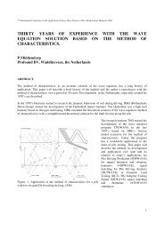
2nd <strong>Statnamic</strong> Seminat, Tokyo, 1998 1<br />
<strong>When</strong> <strong>to</strong> Apply Dynamic Load Testing <strong>and</strong> <strong>Statnamic</strong> Testing<br />
P.Middendorp, <strong>Profound</strong> <strong>BV</strong>, www.profound.nl<br />
R.J. van Foeken, TNO Building <strong>and</strong> Construction Research<br />
ABSTRACT: Pile capacity testing by high strain dynamic loading methods is widely applied<br />
because of its economy <strong>and</strong> efficiency compared <strong>to</strong> static load testing methods (SLT).<br />
Frequently applied dynamic loading methods are dynamic load testing (<strong>DLT</strong>) <strong>and</strong> statnamic<br />
testing (STN). The paper will deal with the very often raised question in practice: <strong>When</strong> <strong>to</strong><br />
<strong>apply</strong> <strong>DLT</strong> <strong>and</strong> STN when pile type <strong>and</strong> soil conditions are known. Special attention is given <strong>to</strong><br />
<strong>DLT</strong> on cast in situ piles, <strong>and</strong> complicating fac<strong>to</strong>rs like limited knowledge of concrete material<br />
properties <strong>and</strong> pile shape. The suitability of <strong>DLT</strong> <strong>and</strong> STN is discussed for cast in situ piles <strong>and</strong><br />
driven precast piles by the evaluation of the accuracy, reliability, economy, mobilization of<br />
capacity <strong>and</strong> the chance on pile damage.<br />
Introduction<br />
Pile capacity testing by high strain dynamic loading methods is widely applied because of its economy<br />
<strong>and</strong> efficiency compared <strong>to</strong> static load testing methods (SLT). The most popular dynamic loading<br />
methods are dynamic load testing (<strong>DLT</strong>) by an impact hammer <strong>and</strong> statnamic testing (STN) by launching<br />
a reaction mass from the pile head. <strong>DLT</strong> introduces a short duration shock pulse in<strong>to</strong> the pile. STN<br />
generates a relative long duration push load on<strong>to</strong> the pile head. Extensive descriptions of load testing<br />
methods <strong>and</strong> comparisons are published by Holeyman (1992) <strong>and</strong> Karkee et al (1997). However these<br />
papers do not deal with the very often raised question from practice: <strong>When</strong> <strong>to</strong> <strong>apply</strong> <strong>DLT</strong> <strong>and</strong> STN when<br />
pile type <strong>and</strong> soil conditions are known. The answer <strong>to</strong> this question will be treated in the next<br />
paragraphs.<br />
Special attention is given <strong>to</strong> <strong>DLT</strong> on cast in situ piles, because<br />
the calculation of the pile load is based on signals from strain<br />
transducers mounted on the pile shaft. So for <strong>DLT</strong> the pile load<br />
calculation depends strongly on pile material <strong>and</strong> cross section<br />
properties <strong>and</strong> fac<strong>to</strong>rs complicating the analysis like limited<br />
knowledge of concrete material properties <strong>and</strong> pile shape are<br />
discussed.<br />
Finally the suitability of both <strong>DLT</strong> <strong>and</strong> STN will be evaluated by<br />
taking in<strong>to</strong> account the following points:<br />
- accuracy of the load measurements<br />
- reliability<br />
- economy<br />
- mobilization of capacity<br />
- chance on pile damage<br />
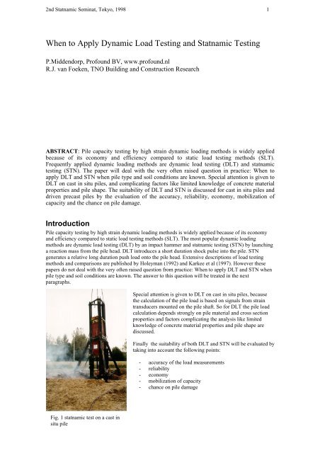
Fig. 1 statnamic test on a cast in<br />
situ pile
2nd <strong>Statnamic</strong> Seminat, Tokyo, 1998 2<br />
The application of <strong>DLT</strong> <strong>and</strong> STN on cast in situ piles<br />
Fig. 2. Dynamic load test on cast in situ pile<br />
For cast in situ piles both <strong>DLT</strong> <strong>and</strong> STN are performed a certain period after pile production, <strong>to</strong> allow the<br />
piles <strong>to</strong> reach the required compressive strength <strong>to</strong> withst<strong>and</strong> the test loads. For <strong>DLT</strong> strain <strong>and</strong><br />
acceleration transducers are mounted on the pile shaft near the pile head. The load displacement behavior<br />
is calculated by signal matching. For STN the load displacement behavior is calculated in most cases by<br />
the Unloading Point Method (UPM), however signal matching techniques are also applied.<br />
Fig. 3. <strong>Statnamic</strong> pis<strong>to</strong>n with<br />
built in load cell placed on a<br />
cast in situ pile<br />
Fig. 4. Strain transducer<br />
mounted on the shaft of a<br />
cast in situ pile<br />
• Accuracy in load measurement for STN<br />
With STN the load is accurately measured by a calibrated load cell placed on the pile head. The measured<br />
load is not dependent on the pile properties. The load measurement error is less than 0.1% of the<br />
maximum range of the load cell.
2nd <strong>Statnamic</strong> Seminat, Tokyo, 1998 3<br />
• Material properties <strong>and</strong> accuracy in load measurement for <strong>DLT</strong><br />
With dynamic load testing strain transducers are mounted on the shaft near the pile head. The load (F) on<br />
the pile head is calculated by multiplying the measured strain (ε) with the modulus of elasticity (E) of the<br />
concrete <strong>and</strong> the pile cross section (A).<br />
F=E.A.ε (1)<br />
The accurate determination of the properties E <strong>and</strong> A for bored piles is difficult in many cases.<br />
To calculate the force from the measured strain in a pile during <strong>DLT</strong> we need <strong>to</strong> know the cross section<br />
<strong>and</strong> the modulus of elasticity of the concrete at the measuring level. For piles with homogeneous material<br />
the stress wave velocity (c) is used <strong>to</strong> calculate the E-modulus with<br />
E = c 2 . ρ (2)<br />
c = 2L/T (3)<br />
Knowing or estimating the stress wave velocity c we can calculate the pile load at the measuring level<br />
with the formula<br />
F= c 2 .ρ.A. (4)<br />
So the derived stress wave velocity has a strong influence on the value of the load measured in the pile.<br />
An error in the measured load will result in an error for the pile capacity prediction.<br />
2L/c<br />
time<br />
c<br />
L<br />
measuring<br />
level<br />
depth<br />
Fig.5 Calculation of stress wave velocity c from<br />
<strong>to</strong>e reflection<br />
The stress wave velocity is calculated from the time (T) it takes for a stress wave <strong>to</strong> travel over the pile<br />
length (L) from the pile head <strong>to</strong> the pile <strong>to</strong>e <strong>and</strong> back <strong>to</strong> the pile head (Fig. 5). For this method it is<br />
required that the reflection coming from the pile <strong>to</strong>e is clearly visible in the signals. In Fig. 6 the force <strong>and</strong><br />
velocity times impedance signals of two dynamic load test are presented. The first case shows a clear <strong>to</strong>e<br />
reflection <strong>and</strong> the stress wave velocity can be calculated accurately. If the <strong>to</strong>e reflection is not visible one<br />
has <strong>to</strong> estimate the <strong>to</strong>e reflection time. However an error in the estimated <strong>to</strong>e reflection time (T) <strong>and</strong> stress<br />
wave velocity (c) will result in a considerable error in the calculation of the E-modulus. For example a
2nd <strong>Statnamic</strong> Seminat, Tokyo, 1998 4<br />
1.8<br />
[MN]<br />
Dynamic Load Test<br />
well visible <strong>to</strong>e<br />
reflection<br />
2.0<br />
[MN]<br />
Dynamic Load Test<br />
no visible <strong>to</strong>e<br />
reflection<br />
1.5<br />
1.3<br />
Pile Length<br />
Wave Velocity<br />
= 16.00 m<br />
= 3500 m/s<br />
1.8<br />
1.5<br />
Pile Length = 17.00 m<br />
Max. Tension Calc.= 13 MPa<br />
Max. Compr. Meas. = 29 MPa<br />
1.0<br />
1.3<br />
0.8<br />
1.0<br />
0.5<br />
0.8<br />
0.3<br />
0.5<br />
0.0<br />
0.3<br />
-0.3<br />
0.0<br />
-0.5<br />
-0.3<br />
-0.8<br />
0.0 6.0 12.0 18.0 24.0 30.0 36.0 42.0 48.0 54.0 60.0<br />
-0.5<br />
0.0 6.0 12.0 18.0 24.0 30.0 36.0 42.0 48.0 54.0 60.0<br />
Time [ms]<br />
Time [ms]<br />
_____ Force ----- Velocity x Impedance<br />
FPDS, PDA, V6.1<br />
_____ Force ----- Velocity x Impedance<br />
FPDS, PDA, V6.1<br />
Fig. 6 Well visible <strong>and</strong> no visible <strong>to</strong>e reflection.<br />
5% error in the stress wave velocity will result in a 10% error for the E-modulus <strong>and</strong> corresponding load<br />
in the pile. Another option in this case is <strong>to</strong> rely on an estimate for the E-modulus from the pile material<br />
properties.<br />
Making an estimate on the E-modulus is difficult because it is not a constant value but depends on the age<br />
<strong>and</strong> the quality of the concrete (Franklin, 1971)(Fig. 7 ), the loading rate (Sparks et all, 1973 ), <strong>and</strong> even<br />
the temperature of the concrete (Abbasi 1990). For example, for static load testing the modulus of<br />
elasticity for concrete is in the range of 28 GPa <strong>to</strong> 32 GPa while for dynamic load testing it is in the range<br />
of 32 GPa <strong>to</strong> 52 GPa<br />
Fig. 7 Relations between dynamic modulus of elasticity <strong>and</strong> age for<br />
concretes made with various aggregates<br />
Another complicating<br />
fac<strong>to</strong>r in determing<br />
the stress wave<br />
velocity c for cast in<br />
situ piles is the fact<br />
that the concrete is<br />
not homogeneous.<br />
The concrete quality<br />
will vary over the<br />
cross section <strong>and</strong> over<br />
the pile axis. The<br />
concrete in contact<br />
with the soil will be<br />
of lesser quality than<br />
the concrete in the<br />
center of the pile <strong>and</strong><br />
the shaft area that has<br />
been in contact with<br />
the soil might be the<br />
location where the<br />
strain transducers are<br />
mounted. The<br />
concrete quality<br />
difference over the pile length is caused by the pouring procedure <strong>and</strong> the difference in concrete pressure<br />
during construction. The quality of the concrete near the <strong>to</strong>e will in general be better than the quality of<br />
the concrete near the pile head. This also means that the stress wave velocity will vary with the pile<br />
length. So the stress wave velocity calculated with c=2L/T is a mean value for the whole pile. The
2nd <strong>Statnamic</strong> Seminat, Tokyo, 1998 5<br />
modulus of elasticity calculated from it represents a mean value for the pile <strong>and</strong> there can be a<br />
considerable difference with the modulus of elasticity at measuring level.<br />
• Influence of pile cross section variations on <strong>DLT</strong> capacity prediction<br />
To predict capacity from <strong>DLT</strong> results, signal matching techniques are<br />
the most frequent applied methods, (TNOWAVE, CAPWAP). Based<br />
on a wave equation computer program calculated signals are matched<br />
with measured signals by adjusting the computer soil model <strong>and</strong> pile<br />
model in an iterative way. <strong>When</strong> signals match it is assumed that the<br />
computer soil model represents the real soil behavior <strong>and</strong> the static pile<br />
capacity is calculated from it.<br />
Fig 8. Cast in situ pile with<br />
bulb<br />
Pile discontinuities like necking, bulbs, <strong>and</strong> material changes introduce<br />
stress wave reflections which can influence the calculated signals<br />
strongly. Reflections from bulbs yield an almost similar wave equation<br />
result as a local stiff soil layer <strong>and</strong> a necking similarly results as a local<br />
soft layer. <strong>When</strong> pile discontinuities are not properly taken in<strong>to</strong> account,<br />
either a proper match cannot be obtained or the capacity prediction will<br />
not be reliable. Soil properties can be confused with pile discontinuities.<br />
• Reliability for testing on cast in situ piles<br />
Because of the many unknowns that have <strong>to</strong> be solved <strong>to</strong> perform a proper <strong>DLT</strong> signal matching analysis<br />
on cast in situ piles, there is considerable chance of errors in pile capacity predictions.<br />
The load measurement for STN is similar as for static load testing <strong>and</strong> unknown pile properties of cast in<br />
situ piles will not influence the load measurement results. During STN the load duration is long enough<br />
that the all pile parts move in the same velocity range. Under these conditions the pile can be considered<br />
<strong>to</strong> act as one mass with a pile rigidity behavior similar <strong>to</strong> static load testing (Middendorp 1995 ) For this<br />
reason pile behavior during STN is closer <strong>to</strong> static load testing than <strong>DLT</strong>.<br />
• Economy<br />
For <strong>DLT</strong> on cast in situ piles a drop hammer with a guiding system has <strong>to</strong> be mobilized. The required ram<br />
mass is as rule of thumb 2% of the maximum load that has <strong>to</strong> be applied. A crane is required <strong>to</strong> move the<br />
drop hammer over the building site. The pile head has <strong>to</strong> be prepared <strong>to</strong> prevent damage from impact<br />
loading. An epoxy or grout cement is used <strong>to</strong> smooth the pile head surface <strong>to</strong> prevent stress<br />
concentrations during impact loading. The location of the transducers has <strong>to</strong> be at least 2 pile diameters<br />
from the pile head. <strong>When</strong> the pile head is loacated at ground level this requires an extension of the pile<br />
head for a similar length or the excavation of the pile head. For small capacity piles multiple piles can be<br />
tested in one day. For loads above 10MN the testing rate is normally in the range of 2 piles per day.<br />
For STN a loading device with a reaction mass catching system has <strong>to</strong> be mobilized. The required<br />
reaction mass is as rule of thumb 5% of the maximum load that has <strong>to</strong> be applied. A crane or a crawler<br />
system is required <strong>to</strong> move the STN device over the building site. For loads up <strong>to</strong> 4MN a STN device<br />
with a hydraulic catch mechanism can be applied. For higher loads STN requires a gravel catch system.<br />
Testing can take between 0.5 <strong>and</strong> 2 days per pile depending on the pile capacity. However for piles with a<br />
capacity less than 4 MN, a loading device with hydraulic catch mechanism can be applied <strong>and</strong> the number
2nd <strong>Statnamic</strong> Seminat, Tokyo, 1998 6<br />
of piles tested in one day are in the same range as with <strong>DLT</strong>. STN can be even more efficient when the<br />
loading device <strong>and</strong> hydraulic catch mechanism are placed on crawlers. An epoxy or grout cement is used<br />
<strong>to</strong> smoothen the pile head surface <strong>to</strong> prevent stress concentrations during push loading.<br />
Table 1. Preferences for <strong>DLT</strong> or STN with respect <strong>to</strong> economy for cast in situ piles<br />
Capacity<br />
<strong>DLT</strong> with drop<br />
hammer<br />
Cast in situ piles<br />
STN device with<br />
gravel catch<br />
mechanism<br />
STN device with<br />
hydraulic catch<br />
mechanism<br />
Up <strong>to</strong> 4 MN **** *** ****<br />
4 MN <strong>to</strong> 10MN **** *** not applicable<br />
10MN <strong>to</strong> 30MN **** *** not applicable<br />
more than 30MN **** *** not applicable<br />
***** = economic<br />
* = not economic<br />
• Chance of pile damage<br />
With <strong>DLT</strong> the load on the pile head is introduced by an impacting ram. <strong>When</strong> the ram is not properly<br />
guided <strong>and</strong> hits the pile in an eccentric way, bending stresses will occur <strong>and</strong> result in excessive<br />
compression <strong>and</strong>/or tension stresses which can damage the pile.<br />
Most cast in situ piles need considerably more displacement <strong>to</strong> mobilize the ultimate capacity than driven<br />
piles. This softer response will easily generate tension waves. Cast in situ piles are not designed <strong>to</strong><br />
withst<strong>and</strong> high tension stresses. As soon as allowable tension stress levels are reached the impact energy<br />
has <strong>to</strong> be reduced <strong>to</strong> prevent pile damage. As a result, <strong>DLT</strong> has <strong>to</strong> be s<strong>to</strong>pped at a stage where full<br />
capacity has not yet been mobilized.<br />
With STN the duration of the loading is long enough <strong>to</strong> keep the pile is under constant compression <strong>and</strong><br />
tension stresses will not occur. To prevent bending stresses the pis<strong>to</strong>n of the statnamic device is installed<br />
exactly on or near the center of the pile head cross section. The launching of the reaction mass, <strong>and</strong> the<br />
resulting push load start from the center of the pile.<br />
The application of <strong>DLT</strong> <strong>and</strong> STN on<br />
precast driven piles<br />
For precast driven piles both <strong>DLT</strong> <strong>and</strong> STN are performed<br />
after a setup period after pile installation. This allows the soil<br />
<strong>to</strong> recover from driving induced disturbances like pore water<br />
pressure. In most cases the soil will regain strength during the<br />
setup period.<br />
For <strong>DLT</strong> strain <strong>and</strong> acceleration transducers are mounted on<br />
the pile shaft near the pile head. The load displacement<br />
behavior is calculated by signal matching.<br />
For STN the load displacement behavior is calculated in most<br />
cases by the Unloading Point Method, however signal<br />
matching techniques are also applied.<br />
Fig 9. Dynamic load test on a precast<br />
pile
2nd <strong>Statnamic</strong> Seminat, Tokyo, 1998 7<br />
• Accuracy<br />
With <strong>DLT</strong> on precast driven piles, the load in pile is measured by strain transducers mounted on the pile<br />
shaft. Precast piles are considered <strong>to</strong> be of homogenous material <strong>and</strong> with the method described in section<br />
2.2 <strong>and</strong> based on the determination of the stress wave the E-modulus can be determined accurately. The<br />
<strong>to</strong>e reflection will be visible at several stages of driving <strong>and</strong> the stress wave velocity can be determined<br />
easily. Only when the pile head is heavily reinforced will the E-modulus at the pile head be different<br />
from the E-modulus calculated by the stress wave velocity.<br />
With STN the load is accurately measured by a calibrated load cell placed on the pile head. The measured<br />
load is not dependent on the pile properties. The load measurement error is less than 0.1% of the<br />
maximum range of the load cell.<br />
• Reliability<br />
The capacity of driven piles is mobilized at relative small displacements.<br />
Both <strong>DLT</strong> <strong>and</strong> STN are performed after a set up period. For <strong>DLT</strong> the pile load displacement behavior is<br />
calculated by a signal matching technique (CAPWAP, TNOWAVE) in most cases.<br />
For STN the pile load displacement behavior is determined by a direct method, the Unloading Point<br />
Method (UPM) <strong>and</strong> in some cases by signal matching.<br />
• Economy<br />
<strong>DLT</strong> has the advantage that the pile driving hammer used for pile installation can also be used for<br />
redriving the piles after a set-up period. However, when the pile driving hammer has <strong>to</strong> be used for<br />
constant production, an additional pile driving hammer or drop hammer has <strong>to</strong> be mobilized. <strong>When</strong> the<br />
mobilization of the full pile capacity is requested, the production hammer might not be sufficient <strong>to</strong><br />
mobilize pile capacity after the set up period <strong>and</strong> an additional heavier hammer has <strong>to</strong> be mobilized.<br />
For STN the same economical conditions are applicable as mentioned in paragraph 2.5.<br />
Table 1. Preferences for <strong>DLT</strong> or STN with respect <strong>to</strong> economy for driven piles<br />
Capacity<br />
<strong>DLT</strong> with pile driving<br />
hammer<br />
Driven piles<br />
STN device with<br />
gravel catch<br />
mechanism<br />
STN device with<br />
hydraulic catch<br />
mechanism<br />
Up <strong>to</strong> 4 MN ***** *** *****<br />
4 MN <strong>to</strong> 30 MN ***** *** not applicable<br />
more than 30MN ***** *** not applicable<br />
***** = economic<br />
* = not economic<br />
• Mobilization of capacity<br />
Set up phenomena can increase the soil resistance considerably. The pile driving hammer used for pile<br />
installation might not be able <strong>to</strong> mobilize the full pile capacity in such a case.<br />
Another reason that capacity can not be mobilized with <strong>DLT</strong> is that the load cannot be increased because<br />
compression or tension stresses becoming <strong>to</strong>o high.
2nd <strong>Statnamic</strong> Seminat, Tokyo, 1998 8<br />
To mobilize the pile capacity a STN device will be sent <strong>to</strong> the building site with at least a corresponding<br />
loading capacity. Only when the piles are overdesigned will the full bearing capacity not be mobilized.<br />
Table . Preferences with respect <strong>to</strong> set up phenomena <strong>and</strong> mobilization of capacity<br />
Driven piles<br />
Soil set up <strong>DLT</strong> STN Preferred method<br />
low <strong>to</strong> medium ***** ***** <strong>DLT</strong>/STN<br />
medium <strong>to</strong> high ** ***** STN<br />
***** = capacity fully mobilized<br />
* = capacity not mobilized<br />
• Chance of pile damage<br />
For <strong>DLT</strong> the are some cases with a chance of pile damage. In the case of low friction <strong>and</strong> a soft <strong>to</strong>e<br />
response tension waves will be generated during <strong>DLT</strong>. <strong>When</strong> the maximum allowable tension stresses are<br />
reached the load on the pile cannot be increased because this will generate higher tension stresses <strong>and</strong> the<br />
pile will experience damage. In the case of a pile with a hard <strong>to</strong>e response, for example pile <strong>to</strong>e on rock,<br />
the compressive stresses at the pile <strong>to</strong>e can theoretically be two times higher than the maximum<br />
compression stress at the pile head. This is caused by the superposition of compression stress waves at<br />
the pile <strong>to</strong>e. So, if during <strong>DLT</strong> the compression stresses at the pile head are higher than half the<br />
compressive strength of the pile material, collapse of the pile material at the pile <strong>to</strong>e will occur. In this<br />
case piles can only be tested up <strong>to</strong> half the compressive strength of the pile material, which may not<br />
correspond with the capacity of the pile.<br />
For STN the pile is kept under constant compression <strong>and</strong> tension waves are suppressed. Superposition of<br />
compression waves at the pile will not occur. As with SLT piles can be tested near <strong>to</strong> the compressive<br />
strength of the shaft.<br />
Preferences with respect <strong>to</strong> soil resistance <strong>and</strong> pile material stresses<br />
Driven piles<br />
Soil resistance Tension stresses Compression stresses<br />
shaft friction<br />
<strong>to</strong>e <strong>DLT</strong> STN <strong>DLT</strong> STN Preferred method<br />
resistance<br />
low <strong>to</strong> medium soft xxxxx x *** *** STN<br />
medium <strong>to</strong> stiff soft xxxx x *** *** STN<br />
low <strong>to</strong> medium medium xx x *** *** <strong>DLT</strong>/STN<br />
medium <strong>to</strong> stiff medium xxx x *** *** <strong>DLT</strong>/STN<br />
low <strong>to</strong> medium high xxx x ***** *** <strong>DLT</strong>/STN<br />
medium <strong>to</strong> stiff high xxxxx x ***** *** STN<br />
xxxxx - high tension stresses ***** - medium compression stresses<br />
x - no tension stresses * - high compression stresses
2nd <strong>Statnamic</strong> Seminat, Tokyo, 1998 9<br />
Conclusions<br />
For bored concrete piles, auger piles <strong>and</strong> caissons the dynamic load testing method is less suitable <strong>and</strong><br />
statnamic load testing is the preferred method. The most important reasons for the preference of statnamic<br />
load testing in the case of cast in situ piles are:<br />
1. Accuracy in load measurement<br />
STN is not dependent on pile material <strong>and</strong> cross section properties<br />
2. No influence of cross sectional variationsSTN results are not influenced by cross sectional<br />
variations over the pile length<br />
3. No tension during compressive testing<br />
STN long duration loading will keep pile under constant compressive pressure<br />
4. Concentric loading<br />
Easy placement of STN loading device in center of the pile<br />
5. Pile <strong>and</strong> soil response closer <strong>to</strong> static<br />
With STN the pile moves as one unit, similar <strong>to</strong> static load tests.<br />
Stress wave phenomena can be neglected resulting in a simple method of analysis<br />
For driven piles both <strong>DLT</strong> <strong>and</strong> STN methods can be applied reliably <strong>and</strong> each has its advantages <strong>and</strong><br />
disadvantages. A big economic advantage for <strong>DLT</strong> can be the use of the production rig for testing. A big<br />
advantage for STN is the fact that maximum available energy can be used <strong>to</strong> mobilize capacity <strong>and</strong> that<br />
that testing does not have <strong>to</strong> be s<strong>to</strong>pped when tensional stresses become <strong>to</strong>o high like with <strong>DLT</strong>.<br />
References<br />
Static <strong>and</strong> Dynamic Tests for Evaluation of the Vertical Load Bearing Capacity of Piles.<br />
Madan B. Karkee, Takashi Horiguchi, Hideaki Kishida, pp199-213<br />
Holeyman, A.E., 1992. Keynote Lecture: Technology of Pile Dynamic Testing. Proceedings of the Fourth<br />
International Conference on the Application of Stress-wave Theory <strong>to</strong> Piles, The Hague, F.B.J. Barends,<br />
Edi<strong>to</strong>r, A.A. Balkema Publishers, pp195-215.<br />
Abbasi, A.F., Al-Tayyib,1990. Effect of hot weather on pulse velocity <strong>and</strong> modulus of elasticity of<br />
concrete. Materials <strong>and</strong> Structures, 1990, 23, pp334-340<br />
Franklin, R.E., King, T.M.J. 1971, Relations between compressive <strong>and</strong> indirect-tensile strength of<br />
concrete, Road Research Labora<strong>to</strong>ry, RRL Report LR 412<br />
Sparks, P.R., Menzies, J.B., 1973. The effect of rate of loading upon the static <strong>and</strong> fatique strength of<br />
plain concrete in compression. Magazine of Concrete Research, Vol 25/ 1973, No. 83, pp 73-80.