
You also want an ePaper? Increase the reach of your titles
YUMPU automatically turns print PDFs into web optimized ePapers that Google loves.
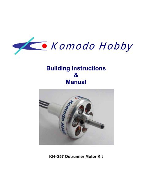
<strong>Komodo</strong> <strong>Hobby</strong><br />
Building Instructions<br />
&<br />
Manual<br />
KH–257 Outrunner Motor Kit
<strong>Komodo</strong> <strong>Hobby</strong><br />
www.komodohobby.com<br />
Introduction<br />
Congratulations on your purchase of a KH-257 Outrunner Motor Kit. The KH-257 is a<br />
lightweight, high torque outrunner motor with a 22mm diameter 12-tooth stator. 16 magnets<br />
are included and the KH-257 can be built as a 10, 14 or 16 magnet pole motor. Moreover, the<br />
12-tooth stator can also be wound using the LRK or Distributed LRK winding technique.<br />
Please take time to read through this manual before building this powerful KH-257 outrunner<br />
motor.<br />
Warning<br />
Radio Control Model and Outrunner Motor Kit are not toy!!! It contains sophisticated small<br />
parts and is designed for hobby use only. All parts of this outrunner motor kit have to be<br />
assembled and operated with great care. Outrunner motor can produce very high power to<br />
turn gear or spin propeller. It is capable of causing property damage and all bodily harm to<br />
operator or spectators. If you are a novis motor builder, please seek assemble and<br />
operational help from an experienced motor builder.<br />
Be Careful!!!<br />
If this outrunner motor kit is not assembled and operated properly, it can damage or destroy<br />
your electronic speed control, receiver, batteries and relevant equipment.<br />
Parts List<br />
(QTY) Items<br />
(1) Pre-pressed End-Bell and Flux Ring<br />
(1) 22mm 12-tooths Stator<br />
(1) Bearing Tube<br />
(1) 3.17mm x 6.35mm Ball Bearing<br />
(1) 3.17mm x 7.93mm Ball Bearing<br />
(1) 3.17mm Hardened Steel Shaft<br />
(1) 30feet, AWG #28 Enameled Magnet Wire<br />
(16) 4 x 4 x 1.5mm N50 Magnets<br />
(3) Connector Pairs (Male and Female)<br />
(7) Shrinking Tubes<br />
(3) M3 x 3 Screws<br />
(1) C-Clip<br />
Optional Parts: (Not included in this kit)<br />
10 magnet spacer<br />
14 magnet spacer<br />
16 magnet spacer<br />
Note: In order to prevent confusion to beginner, this manual mainly<br />
concentrated on assembling 14 magnet poles and distributed LRK winding. In<br />
appendix II, there is shown the winding method for 16 magnet poles.<br />
1
<strong>Komodo</strong> <strong>Hobby</strong><br />
www.komodohobby.com<br />
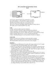
1. Marking Magnets<br />
Stack all magnets together. This will assure all the<br />
magnet poles facing one end of the stack are the<br />
same polarity. Use a marker to mark the face of<br />
one of the end magnets, then move that magnet to<br />
the other end of the stack. Continue marking and<br />
moving magnets until all magnets have one face<br />
marked.<br />
2. Place magnets inside the bell<br />
Before placing magnets inside the bell, you need to choose the number of magnet<br />
poles from the table below.<br />
The characteristics of different magnet pole set-ups<br />
10 magnet poles 14 magnet poles 16 magnet poles<br />
Magnetic Pattern NSNSNSNSNS NSNSNSNSNSNSNS NSNSNSNSNSNSNSNS<br />
RPM High Middle Low<br />
Torque Low Middle High<br />
Note: In this manual, we choose 14 magnet poles for example.<br />
Place the endbell on the template with the center hole<br />
over the center point.<br />
2
<strong>Komodo</strong> <strong>Hobby</strong><br />
www.komodohobby.com<br />
Use a marker to copy all lines onto the flux ring.<br />
Transfer all lines to the edge of flux ring, and place<br />
seven magnets in the bell with marks facing<br />
inward.<br />
Align the magnets with every other mark and<br />
secure them with a small drop of thin CA glue.<br />
Place seven more magnets into the bell, but this<br />
time the marked faces will not show. They will be<br />
against the flux ring. Check to be sure every other<br />
magnet has the marked face showing and the<br />
magnets are evenly spaced. Then apply a small<br />
drop of thin CA to secure the magnets.<br />
Now you have the magnets installed in the desired<br />
NSNSNSNSNSNSNS pattern.<br />
3
<strong>Komodo</strong> <strong>Hobby</strong><br />
www.komodohobby.com<br />
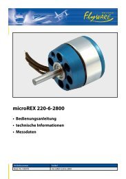
3. Insert bearing tube into stator.<br />
Apply a drop of Loctite (#411, 480 or equivalent) to<br />
the bearing tube and insert it in the stator. Place<br />
the stator on a flat surface and insert the bearing<br />
tube vertically into the stator hole until the end of<br />
the bearing tube is flush with the face of the stator.<br />
4
<strong>Komodo</strong> <strong>Hobby</strong><br />
www.komodohobby.com<br />
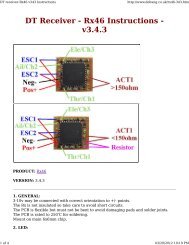
4. Winding<br />
Distributed LRK Winding Diagram (DLRK) for 10 or 14 Magnet Poles<br />
10 magnet poles 14 magnet poles 16 magnet poles<br />
Magnetic Pattern NSNSNSNSNS NSNSNSNSNSNSNS NSNSNSNSNSNSNSNS<br />
DLRK Winding AabBCcaABbcC AabBCcaABbcC ABCABCABCABC<br />
LRK Winding A-b-C-a-B-c A-b-C-a-B-c<br />
• “A” and "a" are first phase wire S1<br />
• “B” and "b" are second phase wire S2<br />
• “C” and "c" are third phase wire S3<br />
• Capital (upper case) letter means Clockwise<br />
• Small (lower case) letter means Anti-Clockwise<br />
• “-“ means the stator tooth not wind<br />
We recommend you mark the stator teeth 1-12, as shown above. It will reduce the chance<br />
of winding the wrong tooth by mistake.<br />
5
<strong>Komodo</strong> <strong>Hobby</strong><br />
www.komodohobby.com<br />
Distributed LRK Winding: AabBCcaABbcC<br />
Please note that this winding can be used for<br />
10 magnet poles (NSNSNSNSNS)<br />
or<br />
14 magnet poles (NSNSNSNSNSNSNS)<br />
It is an example of using three individual magnet wires to complete a 3-phases<br />
system. We recommend beginners to wind 25 turns for their first motor. Please<br />
make sure every coil has same number of turns.<br />
Phase 1 (Tooth 1 & 2)<br />
Step 1: Leave 7-8 cm for making<br />
connections, later.<br />
Step 2: Start the first wire "S1" on tooth<br />
No. 2. Wind 25 turns in a clockwise<br />
direction.<br />
Wind the first layer of 11 turns from the<br />
hub to the hammerhead.<br />
Continue winding the second layer with<br />
8 turns from the hammerhead toward<br />
the hub.<br />
Finish this tooth with 6 turns from the<br />
hub to the hammerhead.<br />
Step 3: Continue this wire to the base<br />
of tooth No. 1 and wind 25 times in the<br />
anti-clockwise direction.<br />
Wind the first layer of 11 turns from the<br />
hub to the hammerhead.<br />
Continue winding the second layer with<br />
8 turns from the hammerhead toward<br />
the hub.<br />
Finish this tooth with 6 turns from the<br />
hub to the hammerhead.<br />
6
<strong>Komodo</strong> <strong>Hobby</strong><br />
www.komodohobby.com<br />
Phase 1 (Tooth 7 & 8)<br />
Step 4: Jump to tooth No. 7 and wind<br />
25 turns in the clockwise direction.<br />
Wind the first layer of 11 turns from the<br />
hub to the hammerhead.<br />
Continue winding the second layer with<br />
8 turns from the hammerhead toward<br />
the hub.<br />
Finish this tooth with 6 turns from the<br />
hub to the hammerhead.<br />
Step 3: Continue this wire to the base<br />
of tooth No. 8 and wind 25 turns in the<br />
anti-clockwise direction.<br />
Wind the first layer of 11 turns from the<br />
hub to the hammerhead.<br />
Continue winding the second layer with<br />
8 turns from the hammerhead toward<br />
the hub.<br />
Finish this tooth with 6 turns from the<br />
hub to the hammerhead.<br />
End wire "S1" by cutting it off leaving<br />
7-8 cm for connections.<br />
7
<strong>Komodo</strong> <strong>Hobby</strong><br />
www.komodohobby.com<br />
Phase 2 (Tooth 5 & 6)<br />
Step 6: Leave 7-8 cm for making<br />
connections, later.<br />
Step 7: Start the second wire "S2" on<br />
tooth No. 6. Wind 25 turns in a<br />
clockwise direction.<br />
Wind the first layer of 11 turns from the<br />
hub to the hammerhead.<br />
Continue winding the second layer with<br />
8 turns from the hammerhead toward<br />
the hub.<br />
Finish this tooth with 6 turns from the<br />
hub to the hammerhead.<br />
Step 8: Continue this wire to the base<br />
of tooth No. 5 and wind 25 times in the<br />
anti-clockwise direction.<br />
Wind the first layer of 11 turns from the<br />
hub to the hammerhead.<br />
Continue winding the second layer with<br />
8 turns from the hammerhead toward<br />
the hub.<br />
Finish this tooth with 6 turns from the<br />
hub to the hammerhead.<br />
8
<strong>Komodo</strong> <strong>Hobby</strong><br />
www.komodohobby.com<br />
Phase 2 (Tooth 11 & 12)<br />
Step 9: Jump to tooth No.11 and wind<br />
25 turns in the clockwise direction.<br />
Wind the first layer of 11 turns from the<br />
hub to the hammerhead.<br />
Continue winding the second layer with<br />
8 turns from the hammerhead toward<br />
the hub.<br />
Finish this tooth with 6 turns from the<br />
hub to the hammerhead.<br />
Step 10: Continue this wire to the base<br />
of tooth No.12 and wind 25 turns in the<br />
anti-clockwise direction.<br />
Wind the first layer of 11 turns from the<br />
hub to the hammerhead.<br />
Continue winding the second layer with<br />
8 turns from the hammerhead toward<br />
the hub.<br />
Finish this tooth with 6 turns from the<br />
hub to the hammerhead.<br />
End wire "S2" by cutting it off leaving<br />
7-8 cm for connections.<br />
9
<strong>Komodo</strong> <strong>Hobby</strong><br />
www.komodohobby.com<br />
Phase 3 (Tooth 9 & 10)<br />
Step 11: Leave 7-8 cm for making<br />
connections, later.<br />
Step 12: Start the first wire "S3" on<br />
tooth No.10. Wind 25 turns in a<br />
clockwise direction.<br />
Wind the first layer of 11 turns from the<br />
hub to the hammerhead.<br />
Continue winding the second layer with<br />
8 turns from the hammerhead toward<br />
the hub.<br />
Finish this tooth with 6 turns from the<br />
hub to the hammerhead.<br />
Step 13: Continue this wire to the base<br />
of tooth No.9 and wind 25 times in the<br />
anti-clockwise direction.<br />
Wind the first layer of 11 turns from the<br />
hub to the hammerhead.<br />
Continue winding the second layer with<br />
8 turns from the hamme head toward<br />
the hub.<br />
Finish this tooth with 6 turns from the<br />
hub to the hammerhead.<br />
10
<strong>Komodo</strong> <strong>Hobby</strong><br />
www.komodohobby.com<br />
Phase 3 (Stator Tooth 3 & 4)<br />
Step 14: Jump to tooth No. 3 and wind<br />
25 turns in the clockwise direction.<br />
Wind the first layer of 11 turns from the<br />
hub to the hammerhead.<br />
Continue winding the second layer with<br />
8 turns from the hammerhead toward<br />
the hub.<br />
Finish this tooth with 6 turns from the<br />
hub to the hammerhead.<br />
Step 15: Continue this wire to the base<br />
of tooth No. 4 and wind 25 turns in the<br />
anti-clockwise direction.<br />
Wind the first layer of 11 turns from the<br />
hub to the hammerhead.<br />
Continue winding the second layer with<br />
8 turns from the hammerhead toward<br />
the hub.<br />
Finish this tooth with 6 turns from the<br />
hub to the hammerhead.<br />
End wire "S3" by cutting it off leaving<br />
7-8 cm for connections.<br />
Picture of a completed 25 turns winding<br />
11
<strong>Komodo</strong> <strong>Hobby</strong><br />
www.komodohobby.com<br />
4. Remove the coating of magnet wires<br />
Now you have 6 wire ends attached to the coils. Use a<br />
sharp knife to scrape off the coating from the last cm of<br />
each wire.<br />
Now, check for any possible shorts between the stator<br />
and each wire or between wires S1, S2 and S3. If any<br />
shorts are found the wire should be removed and new<br />
wire installed. Attempting to run a motor with a short can<br />
damage your electronic speed control, battery, or<br />
receiver.<br />
5. Connecting wires, Delta or Wye system<br />
Now, you need to make you own decision to solder the magnet wires to either Star<br />
(wye) or Delta system.<br />
Star vs Delta<br />
<br />
Star (wye) system gives more torque and uses fewer amps.<br />
In Star system, 1.73 less turns needs to be wound to get the same power and<br />
Kv as DELTA system does.<br />
Delta system gives 1.73 higher power and amps draw compare to STAR<br />
system.<br />
In Delta system, the Kv is 1.73 higher than Star system while the Kt (Torque)<br />
is 1.73 lower<br />
For the winding example above (25Turns), we recommend you to make Delta system.<br />
25Turns, Delta’s Data:<br />
1400Kv<br />
No load current / 8v : 0.5A<br />
No load current / 10v: 0.6A<br />
Resistance (Ohms): 0.1786<br />
For other constant information, please refer to Appendix I<br />
12
<strong>Komodo</strong> <strong>Hobby</strong><br />
www.komodohobby.com<br />
Delta System<br />
Point 1: Solder S1 and E3 together<br />
Point 2: Solder S2 and E1 together<br />
Point 3: Solder S3 and E2 together<br />
Note: Point 1, Point 2 and Point 3 are connected to Electronic Speed Control (ESC)<br />
Star (Wye) System<br />
Solder E1, E2, E3 together<br />
Note: S1, S2 and S3 are connected to ESC.<br />
6. Insert three soldered wires to Shrinking Tubes<br />
Now, you have three soldered wires<br />
attached to coils. Insert those soldered wires<br />
into shrinking tubes for insulating.<br />
7. Put three insulated wires together<br />
Put three wires together and use a short<br />
shrinking tube to secure it.<br />
13
<strong>Komodo</strong> <strong>Hobby</strong><br />
www.komodohobby.com<br />
8. Place ball bearings to bearing tube.<br />
Put a big bearing to front side and small bearing to backside.<br />
9. Insert a main shaft to endbell and put the wound stator into the bell.<br />
10. Put a c-clip into the slot of main shaft.<br />
Put a C-clip to the slot of main shaft to secure<br />
whole motor system.<br />
11. Place three screws at the end-bell.<br />
Place three screws in the end-bell.<br />
Place three M3 x 3 screws into the end bell to<br />
secure the position of the main shaft. Each<br />
screw must be turned a little at a time until all<br />
screws tighten up.<br />
14
<strong>Komodo</strong> <strong>Hobby</strong><br />
www.komodohobby.com<br />
Congratulations!<br />
You finished the assemble work of your KH-257 outrunner motor.<br />
Should you have any comments on this outrunner motor kit, please feel free to<br />
contact us at enquire@komodohobby.com<br />
For other selections of outrunner motor kit, please visit www.komodohobby.com<br />
Firewall Motor Mount Stick Motor Mount<br />
Firewall Motor Mount and Stick Motor Mount for KH-257 Outrunner Motor are<br />
available at www.komodohobby.com.<br />
15
<strong>Komodo</strong> <strong>Hobby</strong><br />
www.komodohobby.com<br />
Appendix I<br />
Magnet: 14 Poles (NSNSNSNSNSNSNS)<br />
Winding: Distributed LRK<br />
Constants of Different Winding<br />
Turns 21 22 23 24 25 26 27<br />
Wire #28 #28 #28 #28 #28 #29 #29<br />
Configuration Delta Delta Delta Delta Delta Delta Delta<br />
Kv 1675 1584 1530 1459 1400 1348 1297<br />
No Load Current / 8v 0.7A 0.6A 0.5A 0.5A 0.5A 0.4A 0.4A<br />
No Load Current / 10v 0.8A 0.7A 0.6A 0.6A 0.6A 0.5A 0.5A<br />
Resistance (Ohms) 0.1479 0.1618 0.1669 0.1699 0.1786 0.2330 0.2590<br />
Weight 0.80oz 0.80oz 0.80oz 0.80oz 0.82oz 0.78oz 0.80oz<br />
22g 22g 22g 22g 23g 21g 22g<br />
16
<strong>Komodo</strong> <strong>Hobby</strong><br />
www.komodohobby.com<br />
Appendix II<br />
Winding: ABCABCABCABC<br />
(For 16 magnet poles)<br />
Wind magnet wire in clockwise direction on all stator teeth.<br />
Winding Diagram for 16 Magnet Poles<br />
17
<strong>Komodo</strong> <strong>Hobby</strong><br />
www.komodohobby.com<br />
Phase 1 (Tooth 1, 4, 7 & 10)<br />
Phase 2 (2, 5, 8 & 11)<br />
18
<strong>Komodo</strong> <strong>Hobby</strong><br />
www.komodohobby.com<br />
Phase 3 (3, 6, 9 & 12)<br />
Star (Wye) System<br />
19
<strong>Komodo</strong> <strong>Hobby</strong><br />
www.komodohobby.com<br />
Delta System<br />
20