R&S®ZVA Vector Network Analyzer Specifications
R&S®ZVA Vector Network Analyzer Specifications
R&S®ZVA Vector Network Analyzer Specifications

You also want an ePaper? Increase the reach of your titles
YUMPU automatically turns print PDFs into web optimized ePapers that Google loves.
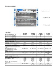
Version 06.00, July 2009<br />
DC MEAS 1 V<br />
Connector type<br />
Voltage range<br />
Measurement accuracy<br />
Resolution<br />
Sample rate<br />
Input impedance<br />
Damage voltage<br />
DC measurement input<br />
4-pin mini DIN, female<br />
–1 V to +1 V<br />
2.5 % of reading + 2.5 mV<br />
12 bit<br />
3 MHz<br />
>10 kΩ<br />
30 V<br />
DC MEAS 10 V<br />
Connector type<br />
Voltage range<br />
Measurement accuracy<br />
Resolution<br />
Sample rate<br />
Input impedance<br />
Damage voltage<br />
DC measurement input<br />
4-pin mini DIN, female<br />
–10 V to +10 V<br />
2.5 % of reading + 25 mV<br />
12 bit<br />
3 MHz<br />
>10 kΩ<br />
30 V<br />
PORT BIAS<br />
Connector type<br />
Maximum nominal input voltage<br />
Maximum nominal input current<br />
Damage voltage<br />
Damage current<br />
DC bias input for PORT<br />
BNC, female<br />
30 V<br />
200 mA<br />
30 V<br />
500 mA<br />
MONITOR<br />
IBM-PC-compatible VGA monitor connector, 15-pin Sub-D (for external monitor)<br />
USER CONTROL<br />
several control and trigger signals, 25-pin Sub-D, 3.3 V TTL<br />
for controlling external generators, for limit checks, sweep signals, etc.<br />
FOOT SWITCH 1 and FOOT SWITCH 2 pin 24 and pin 25 (inputs) control inputs<br />
DRIVE PORT 1 to DRIVE PORT 4 pin 16 to pin 19 (outputs) indicate driving port<br />
CHANNEL BIT 0 to CHANNEL BIT 3 pin 8 to pin 11 (outputs) channel-specific user-configurable bits<br />
PASS 1 and PASS 2 pin 13 and pin 14 (outputs) pass/fail results of limit checks<br />
BUSY pin 4 (output) measurements running<br />
READY FOR TRIGGER pin 6 (output) ready for trigger<br />
EXT GEN TRIGGER pin 21 (output) control signal for external generator<br />
EXT GEN BLANK pin 22 (input) handshake signal from external generator<br />
EXTERNAL TRIGGER pin 2 (input) trigger input for analyzer<br />
EXT TRIGGER<br />
trigger input for analyzer<br />
Connector type<br />
BNC, female<br />
TTL-signal (edge-triggered)<br />
3 V<br />
Polarity (user-selectable)<br />
positive or negative<br />
Minimum pulse width 1 µs<br />
Input impedance<br />
>10 kΩ<br />
Rohde & Schwarz R&S ® ZVA <strong>Vector</strong> <strong>Network</strong> <strong>Analyzer</strong> 29