instruction sheet in pdf - Stark Electronics
instruction sheet in pdf - Stark Electronics
instruction sheet in pdf - Stark Electronics

You also want an ePaper? Increase the reach of your titles
YUMPU automatically turns print PDFs into web optimized ePapers that Google loves.
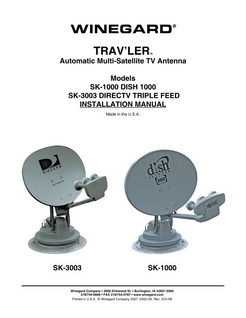
WINEGARD ®<br />
TRAV’LERTM<br />
Automatic Multi-Satellite TV Antenna<br />
Models<br />
SK-1000 DISH 1000<br />
SK-3003 DIRECTV TRIPLE FEED<br />
INSTALLATION MANUAL<br />
Made <strong>in</strong> the U.S.A.<br />
SK-3003<br />
SK-1000<br />
W<strong>in</strong>egard Company • 3000 Kirkwood St. • Burl<strong>in</strong>gton, IA 52601-2000<br />
319/754-0600 • FAX 319/754-0787 • www.w<strong>in</strong>egard.com<br />
Pr<strong>in</strong>ted <strong>in</strong> U.S.A. © W<strong>in</strong>egard Company 2007 2452126 Rev. 3/31/08
Congratulations!<br />
You have selected the W<strong>in</strong>egard® TRAV’LER Automatic Multi-Satellite TV Antenna. The TRAV’LER<br />
antenna will deliver the ability to view up to five satellites at the same time with unmatched signal<br />
strength, the lowest travel height on the market, maximum HD capabilities and easy to use functionality<br />
– just like you get at home. This manual provides important <strong>in</strong>formation on the <strong>in</strong>stallation and operation<br />
of your TRAV’LER Interface Box. Please take time to read the manual <strong>in</strong> it’s entirety before <strong>in</strong>stall<strong>in</strong>g or<br />
operat<strong>in</strong>g your antenna.<br />
Icons appear<strong>in</strong>g <strong>in</strong> the manual are used for important <strong>in</strong>formation and helpful tips.<br />
Alert <strong>in</strong>dicates important <strong>in</strong>formation regard<strong>in</strong>g<br />
product use, product specifications or procedures.<br />
Important tip offers helpful suggestions or<br />
refers you to a related topic <strong>in</strong> the manual.<br />
Recommended Receivers:<br />
The W<strong>in</strong>egard ® TRAV’LER Automatic Multi-Satellite TV Antenna will work with any DISH Network<br />
or DIRECTV ® receiver currently <strong>in</strong> production. However, we recommend:<br />
- DISH Network : models 311 and 211<br />
- DIRECTV : models D11 and H20<br />
Each receiver will require at least one coax cable. Refer to receiver manual for wir<strong>in</strong>g details.<br />
NOTE: DISH Network’s primary HD satellite, the 129°, may not be available <strong>in</strong> all areas.<br />
Check with your programm<strong>in</strong>g provider for coverage <strong>in</strong> certa<strong>in</strong> areas.<br />
The SK-1000 is compatible with all DISH Network Dish Pro Plus Receivers and the SK-3003 is compatible<br />
with all DIRECTV Triple Feed Receivers. Consult your receiver manual or www.w<strong>in</strong>egard.com if<br />
you have any questions about whether your receiver is compatible.<br />
Before you beg<strong>in</strong> please make sure you have received all necessary parts to properly <strong>in</strong>stall and operate<br />
your TRAV’LER antenna.<br />
- Installation/Operation Manual - TRAV’LER Power supply<br />
- Mount Base with 30’ Cable - Power/Control Cable - Gray Coax Cable 30’<br />
- TRAV’LER Interface Box - Black Coax Cable 30’<br />
- Reflector, LNBF & Feed Arm - Mount<strong>in</strong>g Hardware bag<br />
- 24” AC power cord - Cable Entry Hardware bag<br />
Select<strong>in</strong>g a Location for the TRAV’LER Antenna<br />
Before remov<strong>in</strong>g the TRAV’LER antenna from its box, check with your RV Dealer or manufacturer. Your<br />
RV may be pre-wired or have a re<strong>in</strong>forced area for this system. DO NOT <strong>in</strong>stall <strong>in</strong> a location where a<br />
gap of 3/16” or more exists, as it may damage the roof. See diagram at top of page 3.<br />
When <strong>in</strong>stall<strong>in</strong>g the TRAV’LER on a rubber roof, W<strong>in</strong>egard recommends us<strong>in</strong>g the SKA-004 Roller<br />
Plate. If not us<strong>in</strong>g this plate, make sure that the roller does not come <strong>in</strong> contact with any rib supports<br />
or bubbles <strong>in</strong> the roof when <strong>in</strong> operation. Failure to do so, may result <strong>in</strong> damage to the roof.<br />
Rev. 3/31/08<br />
INSTALLATION<br />
2
Plan your entire <strong>in</strong>stallation before<br />
you start. Determ<strong>in</strong>e the location of<br />
all of your equipment and make sure<br />
cable and wires are long enough to<br />
reach their dest<strong>in</strong>ation po<strong>in</strong>ts.<br />
3/16”<br />
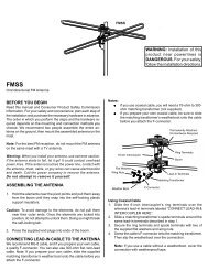
You must f<strong>in</strong>d a location on the roof that provides adequate space to allow the TRAV’LER antenna to<br />
operate. The TRAV’LER antenna has a Front and Back and must be mounted correctly to avoid damage<br />
to the TRAV’LER antenna or the coach. The antenna must be mounted +/-3 degrees of level<br />
or the system may not function correctly. The Transition plate for the TRAV’LER unit is marked<br />
“FRONT” and “BACK”. See Figure 1.<br />
FIGURE 1<br />
!<br />
W<strong>in</strong>egard is NOT liable for damage,<br />
expenses, or <strong>in</strong>jury caused<br />
by improper <strong>in</strong>stallation.<br />
TRANSITION<br />
PLATE<br />
FRONT OF RV<br />
Mount<br />
Parallel to<br />
Center L<strong>in</strong>e<br />
of Coach<br />
Once you have checked for this:<br />
1. Choose a location on the roof of the RV that will allow the dish to raise and rotate without <strong>in</strong>terference<br />
from other roof mounted equipment. The TRAV’LER antenna may only be mounted parallel to<br />
the centerl<strong>in</strong>e of the coach.<br />
FIGURE 2<br />
FRONT OF RV<br />
Mount Parallel to<br />
Center L<strong>in</strong>e of Coach<br />
2. The m<strong>in</strong>imum roof space required for the TRAV’LER antenna is 43” L x 24” W.<br />
a. The operational space requires that no obstructions taller than 8 <strong>in</strong>ches be mounted with<strong>in</strong><br />
a 62” diameter circle from the center of the unit.<br />
3<br />
INSTALLATION
3. The unit must be with<strong>in</strong> 3° of level for best operation.<br />
4. Make sure that the location offers enough support to attach the TRAV’LER antenna securely.<br />
5. F<strong>in</strong>d a well ventilated location with a 110 V outlet for the TRAV’LER Interface <strong>in</strong>side the vehicle.<br />
Make sure to clean the <strong>in</strong>stallation area before you beg<strong>in</strong>.<br />
You will want to decide where the wires will enter the vehicle. One coax cable per receiver and a control<br />
cable will need to be run <strong>in</strong>to the vehicle.<br />
!<br />
Warn<strong>in</strong>g: Do not run the wires through the striped area shown. Consult your receiver<br />
manual for specifics <strong>in</strong> the diagram.<br />
FIGURE 3<br />
20 <strong>in</strong>ches<br />
13 <strong>in</strong>ches<br />
NOTE: Anyth<strong>in</strong>g <strong>in</strong> the striped area will <strong>in</strong>terfere with the operation of the TRAV’LER antenna<br />
and may cause damage to the object or the TRAV’LER antenna.<br />
TRAV’LER Mount Installation<br />
Verify that the “FRONT” of the transition plate is fac<strong>in</strong>g the front of the vehicle then place the TRAV’LER<br />
antenna mount on the roof where you plan to <strong>in</strong>stall it and mark the screw holes so you can see them.<br />
Move the TRAV’LER mount out of the <strong>in</strong>stallation area. It is recommended that you don’t pre-drill theholes.<br />
Use a solid bead of sealant to connect these marks <strong>in</strong> the shape of the base.<br />
Replace the TRAV’LER antenna and screw it to the roof. Check with your vehicle manufacturer for any<br />
special screw requirements before us<strong>in</strong>g the supplied screws.<br />
INSTALLATION<br />
4
FIGURE 4<br />
DO NOT SEAL<br />
!<br />
WARNING: DO NOT cut any<br />
wires when you drill the hole<br />
for your cables.<br />
LIP OF<br />
TRANSITION<br />
PLATE<br />
SEAL<br />
Run a solid bead of sealant around the transition plate, mak<strong>in</strong>g sure to cover each screw head. Be<br />
careful not to get any sealant above the lip of the transition plate. See diagram of transition plate.<br />
Cable Entry Plate Installation:<br />
Decide the best location for the cables to enter the vehicle.<br />
You will need to run:<br />
A coax directly to each receiver location.<br />
A control cable to the TRAV’LER Interface box.<br />
W<strong>in</strong>egard recommends <strong>in</strong>stall<strong>in</strong>g<br />
the Accessory Detect<br />
Cable, this can provide a<br />
emergency stow function.<br />
Drill a 1/2” hole <strong>in</strong> the roof and push the required wires through. (Installations for multiple receivers may<br />
require a larger hole or multiple holes as each receiver requires a dedicated coax cable.) Each receiver<br />
will require at least one coax cable. See receiver manual for wir<strong>in</strong>g details.<br />
Place the cable entry plate supplied <strong>in</strong> hardware bag over the hole and cables. Screw the plate <strong>in</strong> place<br />
and seal the plate and screw holes with approved sealant (not <strong>in</strong>cluded).<br />
Depend<strong>in</strong>g on the length of the cable on the roof, you may need to use cable clamps between the unit<br />
and your cable entry plate. Clamp<strong>in</strong>g every 12-16” should elim<strong>in</strong>ate any unnecessary cable movement.<br />
FIGURE 5<br />
OVERALL INSTALLATION DRAWING<br />
For best results, use TV<br />
1 for the receiver that will<br />
be most active.<br />
POWER<br />
SUPPLY<br />
IDU<br />
A<br />
B<br />
POWER<br />
C<br />
FRONT OF RV<br />
RECEIVER<br />
RECEIVER<br />
ENTRY PLATE<br />
TV 1<br />
RECEIVER<br />
TV 3<br />
TV 2<br />
5<br />
INSTALLATION
Cable <strong>in</strong>stallation:<br />
Connect the control cable and power cable to the back of the TRAV’LER Interface box as shown below. Note:<br />
For cable runs longer than 25’ an extension may be purchased. Do not exceed 50’ of cable.<br />
FIGURE 5<br />
Control Cable<br />
`<br />
`<br />
Power<br />
Attach the TRAV’LER control cable to the TRAV’LER Interface Box, as shown <strong>in</strong> Figure 5.<br />
Attach the output cable from the Power supply to the TRAV’LER Interface Box. See above.<br />
F<strong>in</strong>ally, connect a coax cable from the TRAV’LER mount to each of the receivers be<strong>in</strong>g used with the TRAV’LER<br />
Automatic Satellite Dish. See Appendix for <strong>in</strong>formation on properly <strong>in</strong>stall<strong>in</strong>g a Hex Connector.<br />
F<strong>in</strong>d a location to plug <strong>in</strong> the TRAV’LER Power supply and plug it <strong>in</strong>.<br />
Reflector Installation:<br />
Once the wires are run and the sealant has started to cure:<br />
Check to be sure that there is noth<strong>in</strong>g above the TRAV’LER that might prevent it from rais<strong>in</strong>g. You will need at<br />
least 40” of clearance above the TRAV’LER Mount to ensure that you have room to <strong>in</strong>stall the reflector.<br />
Raise Antenna:<br />
There are two ways to raise the antenna.<br />
Automatic:<br />
Steps 1-7 expla<strong>in</strong> how to use the TRAV’LER Interface box to raise the mount to <strong>in</strong>stall the reflector.<br />
1. Press [POWER] and hold for 2 seconds to turn “ON” the TRAV’LER Interface Box. Wait until the<br />
Interface Box f<strong>in</strong>ishes “connect<strong>in</strong>g to antenna”.<br />
* The TRAV’LER may enter the “Search Rout<strong>in</strong>e” after 10 seconds this is normal (See NOTE Below).<br />
2. Press [ENTER] and hold for 2 seconds or until the unit displays “Enter User Menu”. Press [SELECT] to move the<br />
asterisk to “Yes”. Press [ENTER].<br />
3. Press [SELECT] to move the asterisk to INSTALLATION.<br />
4. Press [ENTER]. You will be asked to provide a code to enter the Installation Menu.<br />
5. Press [ENTER] 4 times to enter code 0000.<br />
6. Press [SELECT] to move the asterisk to RAISE DISH. Press [ENTER]. Press [SELECT] to move the asterisk to Yes.<br />
7. Press [ENTER] the TRAV’LER mount will raise up about half way.<br />
NOTE: If the TRAV’LER enters the “Search Rout<strong>in</strong>e” you can still enter the “Menu Mode”. See Steps A & B.<br />
If the TRAV’LER Mount raises past 1/2 way before RAISE DISH is selected (See Step 6), the TRAV’LER will hit its<br />
Upper Hard Stop and “Motor Stall” appears. This is Normal.<br />
The “Motor Stall” means the TRAV’LER is all the way up & mount can raise no more. There are two easy ways to<br />
clear the “Motor Stall”.<br />
Rev. 3/31/08<br />
INSTALLATION<br />
6
A. Press [ENTER] the TRAV’LER will return to the “Installation Menu”<br />
OR<br />
B. Press [POWER] the TRAV’LER will stow and turn “OFF” (Restart at Step 1).<br />
1. Press [POWER] and hold for 2 seconds to turn “ON” the TRAV’LER Interface Box. Wait until the<br />
Interface Box f<strong>in</strong>ishes “connect<strong>in</strong>g to antenna”.<br />
* The TRAV’LER may enter the “Search Rout<strong>in</strong>e” after 10 seconds this is normal (See NOTE Below).<br />
2. Press [ENTER] and hold for 2 seconds or until the unit displays “Enter User Menu”. Press [SELECT]<br />
to move the asterisk to “Yes”. Press [ENTER].<br />
3. Press [SELECT] to move the asterisk to INSTALLATION.<br />
4. Press [ENTER]. You will be asked to provide a code to enter the Installation Menu.<br />
5. Press [ENTER] 4 times to enter code 0000.<br />
6. Press [SELECT] to move “ * ” to “Calibrate EL”.<br />
7. Press [ENTER].<br />
8. Press [SELECT] to move “ * ” to YES.<br />
9. Press [ENTER] to start the elevation calibration procedure. The LCD should now display “ Calibrate<br />
EL In Progress ...”.<br />
10. After a few moments the IDU LCD will display “On EL Hard Stop?- Yes *No”. Visually exam<strong>in</strong>e<br />
the antenna to verify that the antenna is aga<strong>in</strong>st the Hard Stop. The antenna will be po<strong>in</strong>t<strong>in</strong>g as far up<br />
as it can go, this is the Hard Stop.<br />
11. Press [SELECT] once to move asterisk to “Yes” if antenna is on the Hard Stop.<br />
12. Press [ENTER] and the LCD will display “Calibrate EL Success”.<br />
13. You may now stow the antenna.<br />
Rev. 3/31/08<br />
7 INSTALLATION
WARNING: Pay attention to these P<strong>in</strong>ch Po<strong>in</strong>ts as the antenna raises.<br />
FIGURE 6 FIGURE 7<br />
P<strong>in</strong>ch Po<strong>in</strong>ts<br />
P<strong>in</strong>ch Po<strong>in</strong>t<br />
P<strong>in</strong>ch<br />
Po<strong>in</strong>t<br />
Us<strong>in</strong>g the (4) bolts and nuts provided, attach the reflector to the mount<strong>in</strong>g bracket.<br />
Press [POWER] to lower the antenna to the travel position. Note: The nuts secur<strong>in</strong>g the dish should be<br />
tightened to 6-8 lb.ft.<br />
Receiver Setup:<br />
If you are not able to see all of your channels or the receiver displays an error, it may be necessary to<br />
go through the receiver set up once the TRAV’LER has f<strong>in</strong>ished a successful search.<br />
For DISH Network users:<br />
First, access your Signal Strength screen: Press MENU button. Select “System Setup” (6), “Installation”<br />
(1), “Po<strong>in</strong>t Dish/Signal” (1).<br />
Next perform a Check Switch: You won’t need to perform this test aga<strong>in</strong>, unless check switch is performed<br />
on another dish.<br />
1. From the “Po<strong>in</strong>t Dish/Signal Meter” Screen, use arrow buttons on remote to select “Check Switch”.<br />
2. Select “Test” on this screen to beg<strong>in</strong>.<br />
3. This test should f<strong>in</strong>d A DPP 1K.2 switch.<br />
4. Select “Cancel” from each menu until you are watch<strong>in</strong>g television.<br />
Note: The Procedure may change subtly from model to model, please consult your receiver manual for<br />
details.<br />
For DIRECTV users:<br />
Please refer to your Receiver Manual to enter the Guided Setup, us<strong>in</strong>g oval dish three satellite locations<br />
for antenna type.<br />
INSTALLATION<br />
8
Appendix:<br />
Mak<strong>in</strong>g the Right Connection<br />
with FC-5910 Hex Connectors<br />
Mak<strong>in</strong>g a coaxial cable connection is critical. If you have the<br />
basic technique right you can modify it to your own personal<br />
taste. Whether you use a knife, stripp<strong>in</strong>g tool or diagonal cutter,<br />
the important th<strong>in</strong>g is to make a good clean cut. A hex crimp<strong>in</strong>g<br />
tool is required for hex connectors, for maximum RF transmission.<br />
As mentioned before, the choice of tools is yours. Be sure you<br />
do a precise job. Failure to do so can cost you time and money<br />
<strong>in</strong> try<strong>in</strong>g to locate a system problem.<br />
Cut the cable flush. Strip the outer<br />
jacket off 1/2”, then trim the dielectric<br />
by cutt<strong>in</strong>g partially thru. DO NOT<br />
NICK THE CENTER CONDUCTOR!<br />
Twist and pull off leav<strong>in</strong>g a 1/2” m<strong>in</strong>umum<br />
of exposed center conductor.<br />
Remove additional 1/4” of the outer<br />
jacket.Pull the braid away from the<br />
dielectric and fold over the jacket.<br />
If there’s any residue on the center<br />
conductor scrape off with non-metallic<br />
object.<br />
Slide FC -5910 connector onto coax.<br />
Trim off excess braid.<br />
Look <strong>in</strong>to end of connector to make<br />
sure no braid or alum<strong>in</strong>um foil touches<br />
or has the possibility of touch<strong>in</strong>g the<br />
center conductor. Short<strong>in</strong>g can result<br />
if either comes <strong>in</strong> contact with center<br />
conductor. Close crimp<strong>in</strong>g tool mak<strong>in</strong>g<br />
correct crimp.<br />
IN HOT WEATHER: Trim off center<br />
conductor leav<strong>in</strong>g 3/16” beyond the<br />
connector. The center conductor<br />
expands at higher temperatures. If<br />
a little extra is not provided, it may<br />
contract enough <strong>in</strong> the w<strong>in</strong>ter to create<br />
an open connection and result <strong>in</strong><br />
loss of picture.<br />
IN COLD WEATHER OR INDOORS:<br />
Trim off center conductor leav<strong>in</strong>g it<br />
extended 1/16” of an <strong>in</strong>ch beyond the<br />
connector. (Use diagonal pliers for<br />
cutt<strong>in</strong>g center conductor).<br />
EMERGENCY MANUAL STOW<br />
1. Unplug TRAV’LER Interface.<br />
2. Remove the black plastic bolt from the back of the<br />
mount.<br />
3. Insert a 3/8th socket extension <strong>in</strong>to the auxiliary<br />
drive as shown <strong>in</strong> Figure 1. Turn auxiliary drive clockwise<br />
to lower the unit. NOTE: DO NOT USE A DRILL.<br />
FIGURE 1<br />
AUXILIARY<br />
DRIVE<br />
!<br />
EMERGENCY MANUAL STOW IS<br />
MEANT AS A LAST RESORT AND<br />
NOT FOR COMMON USAGE!<br />
Rev. 3/31/08<br />
9<br />
INSTALLATION
NOTES:<br />
INSTALLATION<br />
10
WINEGARD MOBILE PRODUCTS LIMITED WARRANTY<br />
(2 YEARS PARTS; 1 YEAR LABOR)<br />
W<strong>in</strong>egard Company warrants this product aga<strong>in</strong>st defects <strong>in</strong> materials or workmanship for a period of two (2) years from the<br />
date of orig<strong>in</strong>al purchase. Dur<strong>in</strong>g year one (1) of such warranty, W<strong>in</strong>egard Company will also pay authorized labor costs to<br />
an authorized W<strong>in</strong>egard dealer to repair or replace defective products. No warranty claim will be honored unless at the time<br />
the claim is made, Customer presents proof of purchase to an authorized W<strong>in</strong>egard dealer (to locate the nearest authorized<br />
W<strong>in</strong>egard dealer, contact W<strong>in</strong>egard Company, 3000 Kirkwood Street, Burl<strong>in</strong>gton, Iowa 52601, Telephone 800-288-8094 or<br />
visit www.w<strong>in</strong>egard.com). Customer must provide proof of purchase with a dated sales receipt for the W<strong>in</strong>egard product to<br />
verify the product is under warranty. If the date of purchase cannot be verified, the warranty period shall be considered to<br />
beg<strong>in</strong> thirty (30) days after the date of manufacture.<br />
If a defect <strong>in</strong> material or workmanship is discovered, Customer may take the product to an authorized W<strong>in</strong>egard dealer<br />
for service. Customer must provide proof of purchase to verify the product is under warranty. If the product is brought to an<br />
authorized W<strong>in</strong>egard dealer for service prior to expiration of year one (1) of the warranty period and a defect <strong>in</strong> material or<br />
workmanship is verified by W<strong>in</strong>egard Technical Services, W<strong>in</strong>egard Company will cover the W<strong>in</strong>egard dealer’s labor charges<br />
for warranty service. The W<strong>in</strong>egard dealer must contact W<strong>in</strong>egard Technical Services <strong>in</strong> advance for pre-approval of the<br />
service. Approval of the service is at the sole discretion of W<strong>in</strong>egard Company.<br />
Alternatively, Customer may ship the product prepaid to W<strong>in</strong>egard Technical Services (located at 3111 Kirkwood Street,<br />
Burl<strong>in</strong>gton, Iowa 52601, Telephone 800-788-4417). Customer must return the product along with a brief description of the<br />
problem and provide W<strong>in</strong>egard Technical Services with Customer’s name, address, and phone number. Customer must<br />
also provide proof of purchase to verify the product is under warranty. If the product is returned before the expiration of the<br />
warranty period, W<strong>in</strong>egard Company will (at its option) either repair or replace the product.<br />
This Limited Warranty does not apply if the product has been damaged, deteriorates, malfunctions or fails from: improper<br />
<strong>in</strong>stallation, misuse, abuse, neglect, accident, tamper<strong>in</strong>g, modification of the product as orig<strong>in</strong>ally manufactured by W<strong>in</strong>egard<br />
<strong>in</strong> any manner whatsoever, remov<strong>in</strong>g or defac<strong>in</strong>g any serial number, usage not <strong>in</strong> accordance with product <strong><strong>in</strong>struction</strong>s or acts<br />
of nature such as damage caused by w<strong>in</strong>d, lightn<strong>in</strong>g, ice or corrosive environments such as salt spray and acid ra<strong>in</strong>.<br />
RETURN AUTHORIZATION POLICY<br />
A Return Material Authorization (RMA) is required prior to return<strong>in</strong>g any product to W<strong>in</strong>egard Company or W<strong>in</strong>egard<br />
Warranty Services under this warranty policy. Please call our Technical Services Department at 800-788-4417 or send an<br />
e-mail to warranty@w<strong>in</strong>egard.com to obta<strong>in</strong> the RMA number. Please furnish the date of purchase when request<strong>in</strong>g an RMA<br />
number. Enclose the product <strong>in</strong> a prepaid package and write the RMA number <strong>in</strong> large, clear letters on the outside of the<br />
package. To avoid confusion or misunderstand<strong>in</strong>g, a shipment(s) without an RMA number(s) or an unauthorized return(s)<br />
will be refused and returned to Customer freight collect.<br />
WINEGARD COMPANY DOES NOT ASSUME ANY LIABILITIES FOR ANY OTHER WARRANTIES, EXPRESS OR<br />
IMPLIED, MADE BY ANY OTHER PERSON.<br />
ALL OTHER WARRANTIES WHETHER EXPRESS, IMPLIED OR STATUTORY INCLUDING WARRANTIES OF<br />
FITNESS FOR A PARTICULAR PURPOSE AND MERCHANTABILITY ARE LIMITED TO THE TWO YEAR PERIOD OF<br />
THIS WARRANTY.<br />
In states that do not allow limitations on implied warranties, or the exclusion of limitation of <strong>in</strong>cidental or consequential<br />
damages, the above limitations or exclusions do not apply.<br />
Some states do not allow limitations on how long an implied warranty lasts, or the exclusion of limitation of <strong>in</strong>cidental or<br />
consequential damages, so the above limitations or exclusions may not apply to you.<br />
This warranty gives Customer specific legal rights. Customer may also have other rights that may vary from state to<br />
state.<br />
SATELLITE RECEIVER WARRANTY:<br />
See manufacturer’s limited warranty policy.<br />
Rev. 2/08<br />
! DO NOT pa<strong>in</strong>t this antenna!<br />
Pa<strong>in</strong>t<strong>in</strong>g the TRAV’LER antenna<br />
will void your warranty.<br />
11<br />
INSTALLATION
WINEGARD ®<br />
TRAV’LERTM<br />
Automatic Multi-Satellite TV Antenna<br />
Models<br />
SK-1000 DISH 1000<br />
SK-3003 DIRECTV TRIPLE FEED<br />
OPERATION MANUAL<br />
Made <strong>in</strong> the U.S.A.<br />
SK-3003<br />
SK-1000<br />
W<strong>in</strong>egard Company • 3000 Kirkwood St. • Burl<strong>in</strong>gton, IA 52601-2000<br />
319/754-0600 • FAX 319/754-0787 • www.w<strong>in</strong>egard.com<br />
Pr<strong>in</strong>ted <strong>in</strong> U.S.A. © W<strong>in</strong>egard Company 2007 2452126 Rev. 3/31//08
Congratulations!<br />
You have selected the W<strong>in</strong>egard® TRAV’LER Automatic Multi-Satellite TV Antenna. The TRAV’LER<br />
will deliver the ability to view up to five satellites at the same time with unmatched signal strength, the<br />
lowest travel height on the market, maximum HD capabilities and easy to use functionality – just like<br />
you get at home. This manual provides important <strong>in</strong>formation on the <strong>in</strong>stallation and operation of your<br />
TRAV’LER Interface Box. Please take time to read the manual <strong>in</strong> it’s entirety before <strong>in</strong>stall<strong>in</strong>g or operat<strong>in</strong>g<br />
your antenna.<br />
Icons appear<strong>in</strong>g <strong>in</strong> the manual are used for important <strong>in</strong>formation and helpful tips.<br />
Alert <strong>in</strong>dicates important <strong>in</strong>formation regard<strong>in</strong>g<br />
product use, product specifications or procedures.<br />
Important tip offers helpful suggestions or<br />
refers you to a related topic <strong>in</strong> the manual.<br />
For W<strong>in</strong>egard Warranty Information:<br />
Att: Technical Services<br />
W<strong>in</strong>egard Company<br />
3000 Kirkwood St.<br />
Burl<strong>in</strong>gton, IA 52601<br />
800-788-4417<br />
Disclaimer<br />
Although every effort has been made to <strong>in</strong>sure the<br />
<strong>in</strong>formation <strong>in</strong> this manual is correct and complete,<br />
no company shall be held liable for any errors or<br />
omissions <strong>in</strong> this manual. All <strong>in</strong>formation conta<strong>in</strong>ed<br />
<strong>in</strong> this manual is subject to change without notice.<br />
No warranty of any k<strong>in</strong>d is made with regard to the<br />
<strong>in</strong>formation <strong>in</strong>cluded <strong>in</strong> this manual. The Satellite<br />
Interface is designed specifically for use with<br />
motorized recreational vehicles and <strong>in</strong>formation<br />
conta<strong>in</strong>ed here<strong>in</strong> is provided for that purpose only.<br />
Trademarks<br />
*W<strong>in</strong>egard, TRAV’LER is a trademark of W<strong>in</strong>egard<br />
Company. DISH Network is a registered trademark<br />
of EchoStar Satellite L.L.C. DIRECTV is a<br />
registered trademark of DIRECTV, Inc., a unit of<br />
Hughes <strong>Electronics</strong> Corp. ExpressVu is a registered<br />
trademark of Bell Canada, Inc. All trademarks<br />
conta<strong>in</strong>ed <strong>in</strong> this manual are property of their<br />
respective owners. Reference made to products or<br />
services provided by companies, other than W<strong>in</strong>egard<br />
Company, does not represent any endorsement of<br />
those products or services.<br />
2 OPERATION
Operation<br />
The TRAV’LER offers a simple one button operation that is also protected from accidental searches by a careful<br />
delay. Simply press<strong>in</strong>g the [Power] button will not start a search.<br />
To start a search:<br />
Press and Hold [Power] for two seconds or until the TRAV’LER <strong>in</strong>terface displays<br />
“POWER ON”.<br />
WINEGARD COMPANY<br />
POWER ON<br />
Now the power is ON and the button may be released.<br />
CONNECTING<br />
TO ANTENNA<br />
Once the power is on, the TRAV’LER <strong>in</strong>terface will try to determ<strong>in</strong>e the type of dish that it is work<strong>in</strong>g with. The<br />
TRAV’LER Interface will display the type of satellite dish on the top l<strong>in</strong>e and the action it is tak<strong>in</strong>g on the bottom.<br />
See below.<br />
DIRECTV USERS<br />
DISH NETWORK USERS<br />
DIRECTV TRIPLE<br />
DISH 1000<br />
READY MULTI-SAT<br />
READY MULTI-SAT<br />
The TRAV’LER will enter the search mode as part of its normal operation. The first part of the search is for the<br />
TRAV’LER to f<strong>in</strong>d its “Home” position. Once it f<strong>in</strong>ds it home position it will beg<strong>in</strong> to look for a satellite.<br />
DIRECTV TRIPLE<br />
HOME EL<br />
DISH 1000<br />
HOME EL<br />
DIRECTV TRIPLE<br />
HOME AZ/SK<br />
DISH 1000<br />
HOME AZ/SK<br />
When the TRAV’LER f<strong>in</strong>ds a satellite it will f<strong>in</strong>e tune or “Peak” on the signal and determ<strong>in</strong>e which of the satellites it<br />
has found. Once the TRAV’LER knows which satellite it has found, it can move directly to the correct satellite(s).<br />
The TRAV’LER <strong>in</strong> its automatic search mode will lock onto three different satellites. As it f<strong>in</strong>ishes its search, the<br />
TRAV’LER will display an “*” for each of the satellites it found. See below.<br />
DIRECTV TRIPLE<br />
*101 *110 *119<br />
DISH 1000<br />
*110 *119 *129<br />
Now you are ready to watch TV.<br />
OPERATION<br />
3
Ready to Travel?<br />
To stow the unit when you are ready to travel:<br />
Press [Power] one time.<br />
DIRECTV 1000<br />
STOWING<br />
The unit will stop what it is do<strong>in</strong>g and beg<strong>in</strong> to return to the stowed position. The TRAV’LER Interface WILL NOT<br />
TURN OFF unless the TRAV’LER mount is successfully stowed.<br />
Manual Mode:<br />
The TRAV’LER is an extremely versatile satellite antenna and can be manually set to f<strong>in</strong>d many different satellites<br />
<strong>in</strong>dividually. NOTE: This function is rarely used.<br />
To enter the Manual Search Mode while the TRAV’LER is stowed:<br />
Press the [Power] button and hold it for two seconds to turn the unit on.<br />
While the Trav’ler Interface reads:<br />
WINEGARD BURLINGTON<br />
POWER ON<br />
Press and hold the [Enter] button for two seconds.<br />
The TRAV’LER Interface will ask if you wish to enter the User Menu:<br />
ENTER USER MENU<br />
YES<br />
*NO<br />
Press [Select] to choose YES and then press [Enter].<br />
The User Menu consists of four choices:<br />
Search Mode<br />
Diagnostics<br />
Installation<br />
Exit<br />
NOTE: Diagnostic and Installation Menus are not required for normal operation and should only be entered by a<br />
tra<strong>in</strong>ed professional.<br />
Rev. 1/28/08<br />
4<br />
OPERATION
To use the Manual Search Mode to select a specific satellite, choose Search Mode by press<strong>in</strong>g the [Enter] button.<br />
Once <strong>in</strong> the Search Menu you may choose from:<br />
MULTISAT MODE (The normal search mode)<br />
MANUAL 61<br />
MANUAL 72<br />
MANUAL 82<br />
MANUAL 91<br />
MANUAL 101<br />
MANUAL 110<br />
MANUAL 119<br />
MANUAL 129<br />
MANUAL 148<br />
MAIN MENU (returns to the User Menu)<br />
EXIT (Enters the Search Rout<strong>in</strong>e)<br />
Press [Select] to cycle through each of these satellites until the asterisk is next to the satellite you wish to f<strong>in</strong>d.<br />
Then press [Enter].<br />
The TRAV’LER Interface will ask you to confirm the change:<br />
Manual ###<br />
YES<br />
*NO<br />
Press [Select] to move the asterisk to YES.<br />
The Trav’ler Interface will acknowledge your selection and ask:<br />
The TRAV’LER will rema<strong>in</strong> <strong>in</strong><br />
manual mode until you select<br />
multi-sat mode aga<strong>in</strong>.<br />
POWER OFF<br />
*YES<br />
NO<br />
Press<strong>in</strong>g [Enter] or choos<strong>in</strong>g YES, will stow the TRAV’LER and turn it off.<br />
Press<strong>in</strong>g [Select] then [Enter] or choos<strong>in</strong>g NO will start a new search for your chosen satellite.<br />
EMERGENCY OFF:<br />
The W<strong>in</strong>egard TRAV’LER antenna comes with an emergency Power Off feature.To activate it, press<br />
and hold [POWER] and then press [SELECT] while still hold<strong>in</strong>g [POWER]. The TRAV’LER antenna will<br />
stop where it is and turn off.<br />
!<br />
If the Emergency Power Off is used, the TRAV’LER antenna may not be <strong>in</strong> a safe position for<br />
travel. DO NOT MOVE THE VEHICLE UNTIL YOU ARE ABLE TO STOW THE UNIT.<br />
OPERATION<br />
5
For ExpressVU Users: ExpressVU requires the DISH 1000 SK-1000 system.<br />
To enter the Installation Menu:<br />
while the TRAV’LER is stowed.<br />
Press the [Power] button and hold it for two seconds to turn the unit on.<br />
While the TRAV’LER Interface reads:<br />
WINEGARD BURLINGTON<br />
POWER ON<br />
Press and hold the [Enter] button for two seconds.<br />
The TRAV’LER Interface will ask if you wish to enter the User Menu:<br />
ENTER USER MENU<br />
YES<br />
*NO<br />
Press [Select] to choose YES and then press [Enter].<br />
The User Menu consists of four choices:<br />
Search Mode<br />
Diagnostics<br />
Installation<br />
Exit<br />
Press [Select] to move the asterisk to INSTALLATION then press [Enter].<br />
the TRAV’LER Interface will ask for a code. Enter 0000.<br />
Make sure the asterisk is next to SELECT ANTENNA then press [Enter].<br />
The TRAV’LER antenna may be set for:<br />
DISH 1000<br />
DIRECTV TRIPLE<br />
DIRECTV SLIMLINE<br />
EXPRESSVU<br />
Press [Select] to move the asterisk to EXPRESSVU then press [Enter].<br />
The TRAV’LER Interface will ask you to confirm the change:<br />
EXPRESSVU<br />
YES<br />
*NO<br />
Press [Select] to move the asterisk to YES.<br />
6<br />
OPERATION
TROUBLESHOOTING:<br />
ERROR CODE:<br />
ANTENNA CONNECTION FAILED<br />
EL HOME FAILURE<br />
AZ MOTOR STALLED<br />
EL MOTOR STALLED<br />
SK MOTOR STALLED<br />
STOW FAILURE<br />
ANT NOT STOWED<br />
STOW FAILURE<br />
STOW UNKNOWN<br />
AZ MOTOR RUN REVERSE<br />
EL MOTOR RUN REVERSE<br />
SK MOTOR RUN REVERSE<br />
AZ MOTOR RUNAWAY<br />
EL MOTOR RUNAWAY<br />
SK MOTOR RUNAWAY<br />
NO LNB VOLTAGE<br />
UNKNOWN ERROR ######<br />
DC MOTOR NOT FOUND<br />
ANTENNA WILL NOT AUTOMATICALLY STOW<br />
POSSIBLE SOLUTION:<br />
Check the data cable connection on the back of the Trav’ler Interface.<br />
It may not be connected properly.<br />
Someth<strong>in</strong>g is prevent<strong>in</strong>g the TRAV’LER Mount from rais<strong>in</strong>g as it attempted<br />
to f<strong>in</strong>d the HOME position. Look for obstructions if unit has<br />
recently been manually raised, or the electronics have been replaced.<br />
The calibration may need to be reset. Contact W<strong>in</strong>egard Technical<br />
Support 1-(800) 788-4417.<br />
Someth<strong>in</strong>g is prevent<strong>in</strong>g the TRAV’LER Mount from rotat<strong>in</strong>g, look for<br />
obstructions. If no obvious obstruction, contact W<strong>in</strong>egard Technical<br />
Support 1-(800) 788-4417.<br />
Someth<strong>in</strong>g is prevent<strong>in</strong>g the TRAV’LER Mount from rais<strong>in</strong>g or lower<strong>in</strong>g,<br />
look for obstructions. If no obvious obstruction, contact W<strong>in</strong>egard<br />
Technical Support 1-(800) 788-4417.<br />
Someth<strong>in</strong>g is prevent<strong>in</strong>g the TRAV’LER reflector and LNBF from rotat<strong>in</strong>g,<br />
look for obstructions. If no obvious obstruction, contact W<strong>in</strong>egard<br />
Technical Support 1-(800) 788-4417.<br />
The TRAV’LER is not stowed. Do not try to move the vehicle. Try to<br />
stow the Trav’ler aga<strong>in</strong>. If it fails aga<strong>in</strong>, check for obstructions.<br />
Check the data cable connection on the back of the Trav’ler Interface.<br />
It may not be connected properly.<br />
Contact W<strong>in</strong>egard Technical Support 1-(800) 788-4417.<br />
Contact W<strong>in</strong>egard Technical Support 1-(800) 788-4417.<br />
Contact W<strong>in</strong>egard Technical Support 1-(800) 788-4417.<br />
Contact W<strong>in</strong>egard Technical Support 1-(800) 788-4417.<br />
Contact W<strong>in</strong>egard Technical Support 1-(800) 788-4417.<br />
Contact W<strong>in</strong>egard Technical Support 1-(800) 788-4417.<br />
The TRAV’LER is not see<strong>in</strong>g the required 12-18VDC needed to power<br />
the LNBF. Check the coax connections. If these are all connected<br />
properly Contact W<strong>in</strong>egard Technical Support 1-(800) 788-4417.<br />
Contact W<strong>in</strong>egard Technical Support 1-(800) 788-4417.<br />
Contact W<strong>in</strong>egard Technical Support 1-(800) 788-4417.<br />
See Emergency Manual Stow <strong><strong>in</strong>struction</strong>s. See Page 9 of Installation.<br />
!<br />
Note: Weather and vehicle location can impact the ability of the TRAV’LER to locate all of the required satellites.<br />
!<br />
The Dish 1000’s 129 satellite is not available <strong>in</strong> all parts of the country and ra<strong>in</strong> or snow will reduce the<br />
strength of the 129 satellite. W<strong>in</strong>egard recommends check<strong>in</strong>g with DISH Network for coverage areas.<br />
!<br />
Obstructions such as build<strong>in</strong>gs or tree limbs can block the satellite signals and prevent the TRAV’LER<br />
from successfully locat<strong>in</strong>g all of the satellites for Multi-Sat Mode. Make sure you have a clear view of the<br />
Southern sky.<br />
Rev. 3/31/08<br />
OPERATION<br />
7
NOTES:<br />
8 OPERATION
NOTES:<br />
OPERATION<br />
9