1958-64 impala air ride strongarm front - Ecklers Late Great Chevy
1958-64 impala air ride strongarm front - Ecklers Late Great Chevy
1958-64 impala air ride strongarm front - Ecklers Late Great Chevy

Create successful ePaper yourself
Turn your PDF publications into a flip-book with our unique Google optimized e-Paper software.
By Doc Frohmader<br />
<strong>1958</strong>-<strong>64</strong> IMPALA AIR RIDE STRONGARM FRONT<br />
SUSPENSION<br />
If you’re one of those people who have been thinking about a real<br />
suspension up-grade for your <strong>1958</strong>-19<strong>64</strong> <strong>Chevy</strong>… check this out! This<br />
month we are privileged to present a special tech article by Doc<br />
Frohmader. Doc will be showing you just how easy it is to install Air Ride<br />
Technologies ’58-’<strong>64</strong> Front ShockWave and tubular Strongarm suspension<br />
system. If you’re looking for superior handling and <strong>ride</strong>… this system is<br />
the answer. Thank you Doc for sharing this tech with our subscribers.<br />
Parts Needed:<br />
5<strong>64</strong>928 <strong>1958</strong>-<strong>64</strong> Front ShockWave w/Tubular StrongArms<br />
5<strong>64</strong>923 <strong>1958</strong>-<strong>64</strong> Front CoolRide w/Tubular StrongArms<br />
563293 <strong>1958</strong>-<strong>64</strong> Front CoolRide Using OEM Control Arms<br />
We love our old Impalas and really hate to hear that they<br />
might not measure up to modern suspension technology, but<br />
it’s true. Wallowing, nose diving and understeering were the<br />
standard when these cars were new and no matter how we<br />
romanticize the good old days, it’s something we have to<br />
accept and deal with. Ahhh, the bad old days of bad<br />
suspension!<br />
I put my life in the hands of Greg Schneider at Air Ride<br />
Technologies in a parking lot where he made a few loops<br />
around it at maybe 15 mph in a ’62 Impala, while I shot photos.<br />
The car dove down on the outside wheel so hard the tire was<br />
running almost to the whitewall. The inside tire was nearly off<br />
the ground. Going through a comer, Greg was brave enough to<br />
hit nearly 30 mph (where I had the same day driven a Nova<br />
through at 55 without a problem) and we saw the same near<br />
collapse of the outside and near lift-off of the inner tire. It<br />
didn’t <strong>ride</strong> bad, though, if you like a mushy and wallowing<br />
cruise.<br />
While the car had pretty much state of the art suspension for<br />
1962 American iron, it leaves a lot to be desired compared to<br />
even the most lowly econo-sled of today. A lot of engineering<br />
development has seen light since this car was built and it is<br />
obvious to a massive degree much can be done to improve<br />
handling and <strong>ride</strong>.<br />
In this case, this car was to get a set of StrongArm tubular<br />
steel A-arms backed up with a set of ShockWave combination<br />
<strong>air</strong> spring and billet race-style adjustable shocks. From long<br />
experience, the ART people have learned that cars of this<br />
generation will also need a good sway bar, a set of modern<br />
brakes, and modern tires and rims. These additions will<br />
enhance handling and make the car fully functional at a high<br />
performance level.<br />
On this car, the ART guys started with some cleanup and<br />
inspection. Pressure washing the grease and grime off helps to<br />
see where potential problems are - in addition to making the<br />
work a lot less nasty. Here, to get the rebuilding process started<br />
and make good photos, they ran a wire brush over the area and<br />
shot the remains with some chassis black.<br />
When you disassemble, you’ll find that it is possible to<br />
remove the coils without a spring compressor. However, even<br />
when the A-arm is dropped all the way down, there’s just<br />
enough pressure left so if you get your face in the way you<br />
could get hurt. I recommend that you wrap a chain around the<br />
lower arm and spring so it can’t fly and when you get to where<br />
the arm is all the way down you can use a pry bar to pop the<br />
spring out without it taking off as well.<br />
Same goes for breaking the ball joints loose without getting<br />
into trouble. The best way is to pull all the cotter pins and back<br />
the nuts off far enough so all the threads are cleaned up first.<br />
Otherwise, you will find that instead of the nut spinning off you<br />
just turn the ball inside the housing of the joint. Then, spin<br />
them back on until you get about 1/8 or less gap between the<br />
nut and the spindle, so there is just a little room for the joint to<br />
break and move. Give the connection a good swat with a large<br />
hammer and it should pop apart. Only after the joints are<br />
popped loose and you have the A-arm and spring supported by<br />
the jack, will you remove the upper nut and slowly back the<br />
jack down to release the spring pressure.
Both A-arms are replaced, along with the springs and<br />
shocks so they all get removed and set aside. You will reuse<br />
the original spindles and steering arms as well as the brakes<br />
(unless you upgrade). An upgrade to the sway bar is a real<br />
improvement, but the factory sway bar can be reused with<br />
this kit.<br />
You’ll notice that there are a few small modifications to be<br />
made to the original frame. For one, you’ll have to drill out the<br />
original upper shock mount holes to 5/8” to fit the new<br />
ShockWave mount. To reverse this to stock you’d have to install<br />
a bushing, but that’s a minor deal. Second, you’ll have to open<br />
up the underside of the spring tower, just under the upper<br />
shock mount. This is not visible when the job is done, but it’s<br />
required to get clearance for the upper part of the ShockWave<br />
and it has no affect on original parts should you ever what to<br />
reverse this installation. Finally, you’ll have to drill a hole in the<br />
upper part of the shock tower to allow an <strong>air</strong> line to be run-in.<br />
In all, this is a relatively easy kit to install as Air Ride did a fine<br />
job of engineering the new components to fit properly and to<br />
require minimal alterations. They originally required the re-use<br />
of the original upper A-arm cross shafts, but recently found a<br />
source for reproduction shafts and that is no longer an issue.<br />
New shafts are an extra cost item so you may want to re-use the<br />
originals. I’d say that a reasonably skilled amateur, with basic<br />
tools and a good floor jack and jack stands, can manage this job<br />
with no problem. For the pro installer in a well-equipped shop,<br />
it’s a slam-dunk.<br />
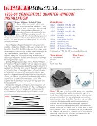
Photo #4: The lower shock mount<br />
is a standard GM arrangement and<br />
comes apart by removing the two<br />
bolts. I’d suggest that you wet all<br />
the old threads with some<br />
penetrating oil a couple times<br />
before starting the job and then just<br />
before. If you snap off a bolt it takes<br />
time to fix, so this is a cheap way to<br />
buy insurance.<br />
#5<br />
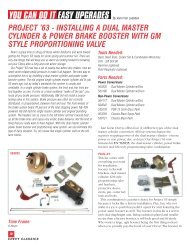
Photo #3: Start disassembly<br />
by removing the upper shock<br />
mount nuts to release the<br />
shock bayonet. Sometimes<br />
this goes easy, but it they are<br />
really rusted together you<br />
might have to cut the<br />
bayonet. If so, be careful not<br />
to damage anything else.<br />
Photo #5: Pull the original<br />
sway bar mounts off at either<br />
end. Here’s another place<br />
where you could easily snap<br />
off hardware, so the<br />
penetrating oil is a good<br />
idea. You can leave the bar<br />
in place and reuse it, but it<br />
may be a good time to<br />
replace the links.<br />
Photo #1: Even at 30 mph, the original suspension was as GM<br />
built it - soft and soggy with a tendency to wallow and dive and<br />
understeer. Today most of us just won’t accept what was state<br />
of the art back then and what is just not safe today. We can do<br />
LOTS better.<br />
Photo #2: The original<br />
suspension is a<br />
relatively modern IFS<br />
with full-width upper<br />
and lower arms, coil<br />
springs, tube shocks<br />
and even a sway bar.<br />
The basics are there<br />
but to get any serious<br />
performance out of it<br />
you need to apply<br />
some current technology and the ART kit is just the ticket.<br />
#6<br />
#7<br />
Photo #6: Often you can<br />
back off the tie rod nuts to<br />
clean threads, then give the<br />
steering arm a sway and the<br />
joint will pop apart. If not,<br />
you’ll need to use a pickle<br />
fork. This is also a good time<br />
to take the brake lines off so<br />
the brake and spindle<br />
assembly can be removed<br />
later.<br />
Photo #7: Support the lower<br />
A-arm with a jack, back off<br />
the ball joint nuts to clean<br />
the threads, then with the<br />
nuts backed off just a bit and<br />
the jack dropped, give the<br />
spindle a good whack with a<br />
hammer and it should pop<br />
loose. The bottom joint gets<br />
the same treatment, but<br />
since there’s no spring<br />
pressure to pop it, you may<br />
need the pickle fork.
Photo #8: Remove the upper<br />
ball joint nut, then SLOWLY<br />
drop the jack to release spring<br />
pressure. For safety, wrap a<br />
length of chain around the<br />
spring and lower arm so the<br />
spring can’t pop out as you do<br />
this. If you have the car set<br />
high enough on the stands,<br />
the lower arm will drop down<br />
far enough to hang. At that<br />
point the spring should be<br />
loose and you can reach in<br />
and lift it out of the way.<br />
#11<br />
Photo #9: Remove the<br />
three retaining bolts<br />
from the lower A-arm<br />
cross shaft and you can<br />
get the old A-arm and<br />
the rest out of the way.<br />
Photo #10: The upper<br />
A-arm is removed by<br />
backing off the two<br />
nuts on the cross shaft<br />
on either side. Preserve<br />
the alignment shims so<br />
you can replace them<br />
for temporary<br />
realignment later.<br />
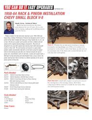
Photo #11:<br />
A comparison of the<br />
original lower arm and<br />
the new StrongArrn.<br />
Can we say that there’s<br />
a BIG difference? These<br />
new arms are made for<br />
ShockWave <strong>air</strong><br />
suspension and require<br />
no additional hardware.<br />
Photo #12: This is<br />
the kit for one<br />
side, plus the<br />
original spindle,<br />
steering arm and<br />
upper A-arm cross<br />
shaft cleaned and<br />
ready to reinstall.<br />
If you don’t have<br />
good upper cross<br />
shafts, you can get new ones for an up-charge from ART.<br />
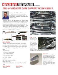
Photo #13: Getting the shafts<br />
out of the A-arms is best<br />
done with an <strong>air</strong> chisel like<br />
this. You’ll want to be careful<br />
not to damage the shaft, but<br />
the bushing is pretty much<br />
toast by the time you get it<br />
out.<br />
Photo #15: On ONE end of<br />
the shaft, you chamfer the<br />
corners of the shaft end.<br />
Here you see the original<br />
and a modified shaft. It<br />
doesn’t harm strength or<br />
function, just makes the<br />
shaft fit through the arm.<br />
Photo #14: The cross shafts have<br />
to be slid inside the A-arm<br />
bushing bosses, but in stock form<br />
this can’t be done. As you can see,<br />
the squared edges of the shaft<br />
prevent this.<br />
Photo #16: The bushings are<br />
installed after the shaft is inserted in<br />
the A-arm. Press them in, don’t beat<br />
them. The shafts are held in just as<br />
in the stock setup by the large flat<br />
washers and bolts. Assemble it all<br />
now, but don’t actually tighten it up<br />
until the whole job is done and the car is sitting at <strong>ride</strong> height.<br />
Photo #17: The upper<br />
ball joints assemble like<br />
this. Yes, there is a right<br />
and wrong way - the dust<br />
seal slides on from the<br />
bottom.<br />
Photo #18: The upper<br />
shock mount holes are<br />
enlarged to 5/8<br />
accommodate the<br />
ShockWave mounts. This<br />
now carries more load,<br />
so the mount is larger.
Photo #19: On the underside of<br />
the spring tower, the opening<br />
you see here must be enlarged<br />
for ShockWave clearance. Check<br />
your clearances! In addition,<br />
note where a hole was drilled in<br />
the top corner for the <strong>air</strong> line. It<br />
will get a rubber grommet for<br />
protection later.<br />
Photo #25: The spindle will<br />
slide onto both ball joint<br />
studs from the bottom.<br />
Tighten both and install the<br />
cotter pins.<br />
#26<br />
#25<br />
Photo #20: The upper<br />
mount parts and <strong>air</strong><br />
fitting are installed like<br />
this. The new swivel<br />
mount on the<br />
ShockWave eliminates<br />
the need for bushings.<br />
Before installing, add<br />
the <strong>air</strong> line as it can’t<br />
be reached after the ShockWave is installed.<br />
Photo #21: The new StrongArm<br />
lower A-arm uses the same<br />
mounting arrangement as stock,<br />
but ART includes these billet<br />
retainer caps. The new lower<br />
cross shafts don’t have the caston<br />
ears.<br />
Photo #22: The original<br />
threaded block is reused, so<br />
make sure the threads are clean<br />
and in good shape. You get this<br />
part by reaching into the spring<br />
pocket above the bolt holes.<br />
Photo #26: The steering<br />
stop bolts on and can be<br />
adjusted or even modified<br />
so you can set it for just<br />
about any wheel and tire<br />
combo. Make sure you<br />
avoid tire rub.<br />
Photo #27: Install the sway<br />
bars links and tighten them<br />
down. Now the brakes can<br />
be reinstalled and bled and<br />
we’re getting close to the<br />
end.<br />
#27<br />
Photo #23: The ShockWave Is<br />
secured at the bottom to the<br />
lower A-arm with a single bolt.<br />
A billet washer is used on<br />
either side between the mount<br />
ears as spacers.<br />
Photo #24: The upper<br />
arms are installed just<br />
the way the originals<br />
were removed. If you<br />
were smart, you saved<br />
the alignment shims<br />
and put them back in<br />
the same place they<br />
were removed - giving<br />
you rough alignment<br />
so you can get the car<br />
to the alignment shop.<br />
Photo #28: The completed assembly not only looks great, but it<br />
performs much better. It is lighter, making the suspension<br />
more nimble. It is stronger. The Shock Wave units not only<br />
have the proven benefits for handling and <strong>ride</strong> that only <strong>air</strong> can<br />
offer, but with the adjustable (up and down, 12-ways each)<br />
shocks inside you can tune this suspension to perform like we<br />
could only dream of in the past.