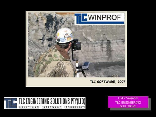
WINPROF - TLC Engineering Solutions
WINPROF - TLC Engineering Solutions
WINPROF - TLC Engineering Solutions

Create successful ePaper yourself
Turn your PDF publications into a flip-book with our unique Google optimized e-Paper software.
L.M.P Valentim<br />
<strong>TLC</strong> ENGINEERING<br />
SOLUTIONS
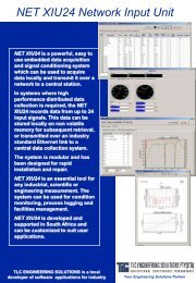
Overview<br />
• <strong>WINPROF</strong> is a software system which<br />
facilitates the design and control of bench<br />
blasts by generating face profile details<br />
• <strong>WINPROF</strong> supports various<br />
laser surveying equipments and<br />
also interfaces to borehole<br />
deviation measurement devices
• Point identification for:<br />
– Crest<br />
– Toe<br />
– Geometry sets<br />
– Boreholes (front and 2..9 rows): up to 1000 boreholes can be<br />
measured<br />
Overall Features<br />
• Ability to read data from a number of laser surveying<br />
instruments:<br />
– Laser Technologies Criterion, Autoscan and Impulse 200<br />
– MDL Autoscan and FastScan format, Quarryman II<br />
– Pulsar Lasers<br />
– Ascii File (generated from<br />
CAD or survey packages)<br />
• Displaying the raw data in<br />
graphical format for editing
Raw Data Editing Tools<br />
• Raw Data can be converted to real mine<br />
coordinates by using a back sight, or by<br />
surveying three known stations.<br />
• Raw Data points may be removed<br />
individually<br />
• Data Limits can be used on the plan view to<br />
remove unwanted data points:
3d Visualization of Raw Data
Database of Fixed Stations<br />
• Database of fixed surveyed station points:<br />
• Surveyed station points<br />
data can be inserted at<br />
different points:<br />
– To define laser station<br />
– To define measured sights
Features of 3D survey software<br />
• Generates the Bench Face Surface based<br />
on user criteria:<br />
• Optimize borehole length according to<br />
bench height<br />
• Adjust elevation of borehole collars to<br />
elevation of the crest<br />
• Automatic calculation of sub-drill<br />
amount as a percentage of toe burden<br />
• Calculate borehole profile using a 3D<br />
surround algorithm (i.e. looking to the<br />
sides of each profile for minimum<br />
burdens)<br />
• Check for minimum burden above and<br />
below at each burden depth
Generated 3D Survey Faces
3d View of Generated Face
Borehole Profiles<br />
• Determination of Borehole Variables:<br />
– Burden at Depth<br />
– Borehole Volume<br />
– Profile Area<br />
– Optimum Borehole<br />
Position<br />
Calculated<br />
Data<br />
Profile Generated<br />
from random Laser<br />
Surveyed Points
Surround Algorithm Calculations<br />
• For each profile, Winprof determines the minimum burden at<br />
depth by calculating the minimum distance to any point on the<br />
rock surface for the burden plane.<br />
3D visualization of algorithm calculations:<br />
Red line shows<br />
minimum<br />
burden occurs out<br />
of the<br />
profile plane
Burden check above/below:
Profile Editing Tools<br />
• Interactive Optimization of Burden Spacing<br />
– Borehole Angle<br />
– Borehole Depth<br />
– Borehole Collar<br />
Positioning<br />
– Profile Line<br />
– Bench floor<br />
slope
Borehole Angle Editing<br />
New Angle<br />
Setting<br />
Mouse drags<br />
borehole
Borehole Depth Editing<br />
New Depth<br />
Setting<br />
Mouse changes<br />
borehole depth
Burden Optimization<br />
• This option calculates the required borehole collar<br />
position to meet one of the following criteria:<br />
• Minimum Burden<br />
• Average Burden<br />
• Maximum Burden<br />
• Fixed Offset from<br />
crest<br />
• Powder Factor<br />
• Can be applied to individual<br />
profiles or to all profiles simultaneously
Borehole Charging<br />
• Winprof provides facilities to define an Explosives<br />
Database with user specific explosives/formulations
Borehole Charging (cont...)<br />
• Each borehole may be loaded individually with:<br />
– Up to 10 decks<br />
– Unloaded decks<br />
(sand/air etc)<br />
– User defined stemming<br />
and backfill<br />
– Equally spaced decks<br />
with air gaps<br />
Defining<br />
Explosives<br />
Decks with the Mouse
Borehole Charging (cont...)<br />
• All boreholes may be loaded automatically:<br />
– According to a predefined loading pattern<br />
– According to user defined criteria based on calculated burden<br />
spacings and borehole depths
Overall Burden Optimization<br />
• Bench Data may be viewed in plan where:<br />
– Boreholes can easily be moved, added and/or deleted<br />
– The Reference Base Line<br />
may be adjusted manually<br />
and/or automatically to<br />
produce better burden<br />
spacings throughout the<br />
face<br />
– The hole collar positions are<br />
adjusted automatically to<br />
ensure that all profile burdens<br />
comply with a user selected<br />
rule (minimum, average or<br />
maximum burdens)
Lifter Boreholes<br />
• Boreholes drilled into the FACE can be<br />
defined as part of the design<br />
• These boreholes are called “LIFTER”<br />
boreholes and are defined in the next page.<br />
• A maximum of 100 lifter boreholes can be<br />
assigned.
Definition of Lifter Boreholes<br />
• Wizard places lifter boreholes along toe line<br />
at specified spacing:
• Holes can be<br />
– Added<br />
– Moved<br />
– Deleted<br />
Lifter boreholes - Front View
Interface with Borehole Angular Deviation Devices<br />
• Winprof interfaces with the following borehole<br />
angular deviation devices:<br />
• BORETRAK<br />
• PULSAR (UK)<br />
• FLEXIT (Sweden)<br />
• DEVIBENCH
Boretrak Interface<br />
• Winprof downloads data directly from the Boretrak CDU unit.<br />
The raw CDU and probe data are immediately available for<br />
editing:
Boretrak Interface (cont)<br />
• Raw data is interpreted to provide<br />
information for each measured borehole:
Boretrak Interface (cont)
3d Visualization of Borehole
Flexit Interface
Flexit Interface (cont)
Angular Deviation Measurements Interface<br />
• Borehole angular deviation<br />
measurements can be linked to the<br />
survey data, automatically, or one<br />
at a time.<br />
• Once the two measurements are<br />
linked, all burden calculations will<br />
be based on the actual<br />
measurements as shown in the<br />
following screens.
3D Survey with Borehole Angular Measurements attached
Borehole Deviation<br />
Actual Borehole<br />
Position
Calculations based on Actual (true) Hole Position<br />
Shaded Area<br />
used for volume<br />
calculations
Reports<br />
• Winprof provides a comprehensive list of reports<br />
including:<br />
– Printout of individual profiles with borehole details, burden<br />
and charging information<br />
– Survey Summary Report<br />
– Borehole Positioning Report<br />
– Inter-Hole Spacing Report (for option with Angular Deviation<br />
Measurement Inputs)<br />
• All reports and printouts can be exported directly to<br />
PDF/RTF/HTML format
Profile Printout
Survey Summary Printout
Borehole Positioning Printout
Inter-Hole Spacing Printout
Boretrak/Pulsar/Flexit Reports<br />
(Angular Deviation Measurements Report)
Blast Pattern Generation<br />
• Winprof provides tools to generate back row<br />
boreholes:
Specifications<br />
• WinProf is a Windows XP/Vista software<br />
product (32bit).<br />
• WinProf supports two other languages<br />
directly:<br />
– Portuguese<br />
– German
• <strong>TLC</strong> <strong>Engineering</strong> <strong>Solutions</strong> (Johannesburg,<br />
South Africa)<br />
– Luis Valentim, Terry Cousins<br />
– sales@tlc.co.za or<br />
luis@tlc.co.za<br />
– www.tlc.co.za<br />
– Tel:+27 11 4633860<br />
• Vibronics (Evansville, Indiana, USA)<br />
– John Wiegand, Jeff Baker<br />
– sales@vibronics.com or<br />
jbaker@vibronics.com<br />
– www.vibronics.com<br />
– Tel: (812) 853 2300<br />
Contact Details: