Download file
Download file
Download file

Create successful ePaper yourself
Turn your PDF publications into a flip-book with our unique Google optimized e-Paper software.
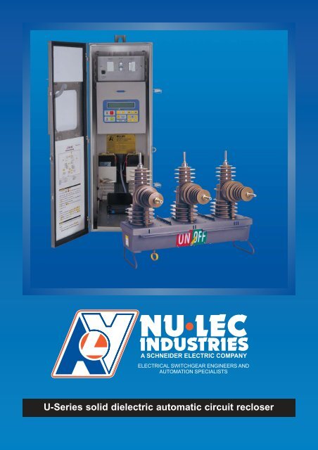
U-Series solid dielectric automatic circuit recloser
Introduction<br />
The U-Series solid dielectric automatic<br />
circuit recloser (also known as a circuit<br />
breaker) represents Nu-Lec Industries’<br />
commitment to improved products and<br />
ongoing product development. It provides<br />
the features of a traditional recloser, plus<br />
the benefits of up to date design optimised<br />
for automation, remote control and<br />
monitoring, now or in the future.<br />
The development of this product was<br />
driven by customer demand for improved<br />
return on capital investment in the<br />
distribution network. After carefully<br />
evaluating customers’ needs, the U-Series<br />
ACR was developed to achieve optimum<br />
performance and reliability, making use of<br />
the very latest available technology in solid<br />
dielectrics, vacuum interruption and<br />
microelectronics. The result is a<br />
competitive world-class product of which<br />
we are justly proud.<br />
In the past, distribution equipment such as<br />
reclosers have been purchased only to<br />
support load growth. Today your<br />
customers, electricity consumers, are<br />
demanding reduced outages and lower<br />
tariffs. We at Nu-Lec Industries are<br />
continually working to provide advanced<br />
equipment needed for tomorrow’s<br />
competitive electricity distribution system.<br />
By using this technologically advanced<br />
equipment, operating costs will be<br />
reduced, revenue will be increased through<br />
reduced outages and capital works can be<br />
deferred through better management of<br />
existing plant.<br />
In addition to automatic circuit reclosers,<br />
the Nu-Lec Industries family of switchgear<br />
includes a range of remotely controlled and<br />
monitored pole mounted load break<br />
switches and sectionalisers as well as<br />
remote control and monitoring software.<br />
This product family is a complete solution<br />
for distribution system automation.<br />
Reduced Purchase Cost<br />
• The V23 FSK modem and Remote Terminal Unit (RTU) are included in the<br />
standard equipment. No additional RTU, modem, power supplies, batteries,<br />
wiring, connectors or enclosures are required.<br />
Reduced Installation Costs<br />
• Commissioning of the unit is simple. Configuration of the device is menu<br />
driven from the Operator Control Panel.<br />
• Pole mounting brackets are provided in the standard package. Lightning<br />
arrester mounting is optional.<br />
Reduced Operating Costs<br />
• The integral protection relay provides fast isolation of faults, reducing<br />
damage.<br />
• The recloser constantly monitors line current and voltage without the need for<br />
additional statistical measurement devices. This data can then be used for<br />
forward planning and optimisation of existing plant. This will reduce<br />
distribution system losses.<br />
• Long lifetime, low maintenance equipment reduces lifetime cost. The solid<br />
dielectric construction ensures a long life, low maintenance product.<br />
Improved Environmental Aspects<br />
• Enclosing the vacuum interrupter in a solid epoxy bushing eliminates the need<br />
for oil or gas insulation.<br />
DSA/SCADA Compatibility<br />
When used with a compatible Distribution System Automation (DSA) or SCADA<br />
system, Nu-Lec Industries automatic circuit reclosers support remote control and<br />
monitoring to provide the following advantages:<br />
• Information on recloser status and fault current values transmitted to system<br />
control allows fast location of the faulted line section, reducing the travelling<br />
time of line crews.<br />
• This same information allows informed remote or automatic switching of lines,<br />
which reduces the area affected and quickly restores supply. Quality of supply<br />
is improved as a result.<br />
• Reclosers can be configured and managed from system control, without<br />
technicians having to visit each individual recloser in the field to change<br />
configuration settings. This allows a reduction in staffing and improved system<br />
integrity.<br />
Increased Revenue<br />
• Supply can be quickly restored to unaffected areas, resulting in less outage<br />
time and therefore increased revenue.<br />
Deferred Capital Works<br />
• Remotely controlled and monitored reclosers give an improved knowledge of<br />
a system and enhance system control. Feeder and substation load can then<br />
be remotely managed and switched, providing cross re-inforcement of<br />
substations and improving utilisation of existing plant. Purchase of new plant<br />
can then most likely be deferred for a considerable period of time.<br />
2 U-Series<br />
Nu-Lec Industries
Recloser Overview and<br />
Operation<br />
15<br />
14<br />
13<br />
12<br />
11<br />
10<br />
9<br />
Cross section of U-Series solid dielectric recloser<br />
Legend<br />
1. X-Side Terminal<br />
2. Vacuum<br />
Interrupter<br />
3. Epoxy bushing<br />
4. Earthing Point<br />
5. Stainless steel tank<br />
6. Magnetic Actuator<br />
7. SCEM card<br />
8. Control cable<br />
9. Manual Trip Ring<br />
10. Pointer<br />
11. Lightning arrester<br />
brackets<br />
12. Stainless steel lid<br />
13. Current<br />
Transformer<br />
14. Capacitive<br />
Voltage<br />
Transformer<br />
15. I-Side Terminal<br />
1<br />
2<br />
3<br />
4<br />
5<br />
6<br />
7<br />
8<br />
The U-Series automatic circuit recloser uses vacuum interrupters,<br />
contained in epoxy bushings, eliminating the need for insulants like<br />
oil and gas. The mechanism is enclosed in a 316 grade stainless<br />
steel tank with a stainless steel lid. The cyclo-aliphatic epoxy resin<br />
casting is bolted onto the lid.<br />
Monitoring and control of the recloser is performed by the field proven Pole Top<br />
Control and Communications cubicle (PTCC), of which many thousand are in<br />
service worldwide. The PTCC houses the Operator Control Panel and<br />
microelectronics that provide the protection functions. It is normally located lower<br />
down the pole for ease of access and is connected to the circuit breaker by a<br />
detachable control cable. The circuit breaker and PTCC together form a remotely<br />
controlled and monitored automatic circuit recloser.<br />
The recloser is operated by a magnetic actuator which produces a positive opening<br />
and closing action. Switching occurs when a controlled pulse is sent through the<br />
open/close actuator from a storage capacitor in the PTCC. When closed, the switch<br />
is latched magnetically. Spring loaded pushrods provide contact loading on the<br />
interrupters.<br />
A Current Transformer (CT) and a Capacitive Voltage Transformer (CVT) are<br />
moulded in the CT-housing. These are monitored by the PTCC for remote<br />
monitoring and display. The PTCC requires an auxiliary AC supply. A control cable<br />
connects the PTCC to the bottom of the circuit breaker through a covered<br />
plug/socket sealing arrangement on both the PTCC and the tank.<br />
The recloser is supplied with copper stems or optional cable clamp connectors.<br />
Mounting brackets for lightning arresters are optionally available.<br />
The recloser contact position is shown by a large, clearly visible external pointer.<br />
A hookstick can be used to engage the manual trip ring to trip and lockout the<br />
recloser from the ground. The mechanical trip ring has two positions. In the “up”<br />
position normal operation takes place. In the “down” position the recloser is tripped<br />
and both mechanically and electronically locked open.<br />
The Pole Top Control Cubicle (PTCC) interfaces to the recloser via the control<br />
cable and connects to the Switch Control Entry Module (SCEM) in the base of the<br />
tank. The SCEM uses EEPROM memory to store all relevant calibration data,<br />
ratings and number of operations conducted. The SCEM also provides the first<br />
stage of electrical isolation and shorting electronics to short the CTs and CVTs in<br />
the event the control cable is disconnected while current is flowing through the<br />
recloser.<br />
U-Series solid dielectric casting<br />
Nu-Lec Industries<br />
U-Series<br />
3
Communications Cubicle<br />
Overview<br />
The advanced protection, data logging and communications<br />
abilities of the U-Series automatic circuit recloser are made<br />
possible by the technology housed in the control and<br />
communications cubicle. It has been designed especially for<br />
outdoor, pole mounted operation and is normally mounted low on<br />
the pole for ease of access by maintenance personnel.<br />
The cubicle is insulated and designed to minimise any temperature rise resulting<br />
from solar heating. An internal equipment panel is used to mount all the equipment,<br />
including the batteries, storage capacitors, mains transformer, low voltage circuit<br />
breakers, Control And Protection Module (CAPM), Operator Control Panel and<br />
radio or modem. These components are carefully located so that the heat<br />
generating parts are at the top, while the battery is at the bottom to keep it cool. In<br />
this way battery life in excess of 5 years can be achieved.<br />
All weather access is provided to the Operator Control Panel through a lockable<br />
door on the front of the control cubicle. Vents are screened against vermin entry<br />
and the door is sealed against the outer with a rubber extrusion. All electronic parts<br />
are well protected from entry of moisture and condensation ensuring a long lifetime.<br />
Three models of control and communications cubicle are available, Tropical,<br />
Moderate and Temperate. The Tropical version is well ventilated and is suitable for<br />
climates where the ambient temperature can reach 50°C and only occasionally<br />
goes below 0°C, with a lower limit of -10°C.<br />
The Moderate version has reduced ventilation and is used where temperatures<br />
rarely go above 40°C and occasionally go below -5°C, with a lower limit of -15°C.<br />
The Temperate model has a heater installed, making it suitable for climates where<br />
the temperature rarely goes above 40°C but can fall as low as -30°C.<br />
All three cubicles are fitted with the same electronics and incorporate the functions<br />
of an overcurrent protection relay, a sensitive earth fault relay, a reclose relay, and<br />
a remote terminal unit. Additionally, the electronics measure line current, voltage,<br />
real and reactive power, fault currents, and stores these for transmission or off-line<br />
analysis.<br />
Pole Top Control & Communications Cubicle<br />
A unique feature of the Nu-Lec Industries automatic circuit recloser is the built-in<br />
microprocessor controlled power supply. This provides uninterrupted operation of<br />
not only the circuit breaker and protection relay, but also the communications radio<br />
or modem. No other power supplies are required for connection into your SCADA<br />
or Distribution Automation System.<br />
Due to careful design the efficiency of all parts is extremely high, allowing a battery<br />
hold up time of five days after auxiliary supply failure (from fully charged battery,<br />
excluding telemetry radio or modem usage). The architecture used has the<br />
advantage that the circuit breaker operation is independent of the high voltage<br />
supply, relying on a set of batteries charged by the auxiliary supply.<br />
Due to sophisticated power supply management techniques, a circuit breaker<br />
operation is always guaranteed when attempted and alarms are raised over the<br />
telemetry when auxiliary power is lost.<br />
A communications radio or special modem can be mounted within the control and<br />
communications cubicle. A V23 FSK modem is included as standard equipment.<br />
Control and Protection Module (CAPM) Circuit Board<br />
4 U-Series<br />
Nu-Lec Industries
Block Diagram & Features<br />
CIRCUIT BREAKER<br />
OPTIONAL<br />
EXTERNAL<br />
CT<br />
CVT<br />
HV LINE 3 PHASES<br />
CVT<br />
TRIP / CLOSE<br />
ACTUATOR<br />
MEMORY<br />
AUXILIARY<br />
SWITCHES<br />
VACUUM<br />
INTERRUPTER<br />
CONTROL<br />
CABLE<br />
UN-INTERRUPTABLE<br />
BATTERY<br />
POWER SUPPLY<br />
TRIP<br />
CAPACITOR<br />
ACTUATOR<br />
POWER<br />
SUPPLY<br />
CLOSE<br />
CAPACITOR<br />
MODEM<br />
V23 FSK<br />
CONTROL CUBICLE ENTRY MODULE<br />
DIGITAL<br />
INTERFACE<br />
MICRO<br />
PROCESSOR<br />
SERIAL<br />
INTERFACE<br />
RS232<br />
SPI<br />
RS232<br />
RADIO<br />
MODEM<br />
REMOTE<br />
I/O CARD<br />
OPERATOR<br />
SUB SYSTEM<br />
PANEL<br />
CONTROL CUBICLE<br />
AUX<br />
POWER<br />
SUPPLY<br />
ANALOGUE TO DIGITAL<br />
CONVERSION<br />
ANALOGUE FRONT END<br />
CONTROL &<br />
PROTECTION<br />
MODULE (CAPM)<br />
WSOS<br />
OPERATOR<br />
PC<br />
Automatic circuit recloser block diagram<br />
--------- OPERATOR SETTINGS --------S<br />
Local Control ON E/F OFF, SEF OFF<br />
Auto Reclose OFF Cold Load IDLE<br />
Single Shot Active Prot ‘A’ Active<br />
Operator control panel<br />
The Nu-Lec Industries automatic circuit reclosers provide many<br />
outstanding advantages to the user. New and innovative features<br />
have been made possible by the intimate way the pole mounted<br />
circuit breaker and communications cubicle work together. The<br />
block diagram below shows how the two items are interfaced. The<br />
heart of the unit is the Control and Protection Module (CAPM) and<br />
the intelligent Operator Control Panel.<br />
HV Line signals are connected into the electronics module by direct connection to<br />
the analogue front end. Special extended range current transformers provide a<br />
range from 1A to 12,500A for measurement and protection. Embedded voltage<br />
screens accurately image the primary voltage value and phase relationship,<br />
allowing measurement of voltage, current, power factor and frequency in the<br />
electronic module.<br />
Each recloser is provided with an Operator Control Panel which has a four line<br />
liquid crystal display with back lighting for night operation. From here a user can<br />
access and program the many measurement and protection features available.<br />
Three levels of user interface with the Operator Control Panel are provided as<br />
follows:<br />
1. Operator Level<br />
This allows basic operation like Trip, Close and display of settings, such as:<br />
• Protection settings and fault history<br />
• Line measurements and historical data<br />
• Recloser functions such as:<br />
Remote control<br />
ON<br />
Local control<br />
ON<br />
Sensitive Earth Fault ON/OFF<br />
Earth Fault<br />
ON/OFF<br />
Auto reclose mode<br />
ON/OFF<br />
Close/Trip<br />
ISOLATE<br />
• Alarms/Status such as:<br />
Auxiliary supply fail<br />
Battery supply fail<br />
Lockout<br />
2. Technician Level<br />
This level is password protected at the user’s discretion in the “Engineer Level” and<br />
allows the setting of all protection related parameters.<br />
3. Engineer Level<br />
This is accessible through a laptop or desktop computer only and allows advanced<br />
customisation of the operator panel, setting of passwords, and all the Operator and<br />
Technician Level functions.<br />
Telemetry Interface<br />
The Nu-Lec Industries automatic circuit recloser can be interfaced to your SCADA<br />
system either through its built-in V23 modem and a radio, or its RS232 port and a<br />
modem of your choice. A variable voltage uninterruptable power supply is included<br />
for the radio or modem, which can be mounted inside the communications cubicle.<br />
Almost all telemetry protocols can be supported. DNP3, IEC870, Conitel and<br />
Modbus are some of the available protocols.<br />
Computer Interface<br />
The Windows Switchgear Operating System (WSOS) is an advanced personal<br />
computer based software package to allow off-line and on-line programming,<br />
monitoring and control of a recloser via the RS232 port. This is available as an<br />
option to the basic Nu-Lec Industries recloser.<br />
Remote Control<br />
As an additional option, Nu-Lec Industries offers the WSOS multiple connect PC<br />
based software package to individually remote control and monitor a population of<br />
field mounted reclosers and/or load break switches. The system communicates with<br />
the control cubicle by either cable, fibre optic, telephone line or radio. WSOS<br />
provides additional features such as alarm and event handling, dial in and dial out<br />
facilities and report generation.<br />
Nu-Lec Industries<br />
U-Series<br />
5
General Protection<br />
Features<br />
Operating Sequence<br />
Reclose times are individually selectable. The operating sequence is defined by:<br />
O - 1st r t -CO - 2nd rt - CO - 3rd rt - CO where rt = reclose time.<br />
Reclose Times<br />
1st reclose time:<br />
0.5 - 180 sec<br />
2nd reclose time:<br />
2.0 - 180 sec<br />
3rd reclose time:<br />
2.0 - 180 sec<br />
Timing resolution:<br />
0.1 sec<br />
Fast Trip Input Module<br />
This module is available as an accessory. It provides an optically isolated input to<br />
unconditionally trip the recloser within 60ms of activation (including debounce and<br />
breaker operating time). This module is purchased as an additional hardware item.<br />
For further details or application suitability, refer to Nu-Lec Industries.<br />
Sequence Reset Time<br />
Sequence reset time:<br />
5 - 180 sec<br />
Timing resolution:<br />
1 sec<br />
Trips to Lockout<br />
Overcurrent and fault trips to lockout are selectable between 1 and 4.<br />
A separate setting is available for Sensitive Earth Fault (SEF).<br />
Inverse Time Curves<br />
The CAPM offers a total of 48 user selectable inverse time protection curves.<br />
These are:<br />
Three IEC255 curves:<br />
Standard Inverse,<br />
Very Inverse and<br />
Three IEEE C37.112 Inverse Time curves:<br />
Extremely Inverse.<br />
Moderately Inverse,<br />
Very Inverse and<br />
Extremely Inverse.<br />
42 Non Standard Inverse Time Curves: Refer to the Technical<br />
Manual for a full listing.<br />
User Defined Curves<br />
Up to five User Defined Curves (UDCs) may be selected at the control panel in the<br />
same manner as the above curves. The UDC module in WSOS is used to<br />
configure the UDCs.<br />
Instantaneous Protection<br />
Instantaneous Protection works by tripping the recloser if the line current exceeds<br />
the Instantaneous Multiplier x Setting Current.<br />
Multiplier Range: 1 - 30<br />
Resolution of setting: 0.1<br />
Max effective setting:<br />
12.5kA<br />
Definite Time Protection<br />
Definite Time is available on phase and earth protection as an alternative to<br />
Inverse Time protection. It works by tripping the recloser at a fixed time after<br />
pickup.<br />
Setting current range:<br />
10 - 1260A<br />
Definite time resolution:<br />
0.1 sec<br />
Definite time range:<br />
0.5 - 100 sec<br />
Setting current resolution:<br />
1A<br />
Sensitive Earth Fault (SEF)<br />
SEF causes the recloser to trip when the earth current rises above a set level for<br />
longer than the set time.<br />
SEF trip current range:<br />
4 - 20A<br />
SEF operating time:<br />
0.1 - 100 sec<br />
SEF trip current setting resolution:<br />
1 A<br />
SEF operating time resolution:<br />
0.1 sec<br />
Sequence Coordination<br />
Sequence Coordination allows a recloser to keep its trip sequence in step with<br />
another recloser downstream.<br />
6<br />
U-Series<br />
Nu-Lec Industries
Advanced Protection<br />
Features<br />
Directional Blocking<br />
Directional blocking is an additional protection feature that restricts tripping on<br />
faults to a designated side of the recloser. It prevents nuisance tripping if particular<br />
network conditions are causing “false” earth faults. In radial systems Directional<br />
Blocking prevents nuisance tripping by blocking faults in the source direction and<br />
only responding to faults in the load direction.<br />
Live Load Blocking<br />
Live Load Blocking prevents a recloser from closing if any of the load side terminals<br />
are live.<br />
Live Load Threshold Voltage Range:<br />
2 - 15kV<br />
Loss of Phase<br />
Loss of Phase Protection trips the recloser if phase-ground voltage on one or two<br />
phases falls below a set voltage threshold for a set length of time.<br />
Threshold voltage range:<br />
2 - 15kV<br />
Voltage resolution:<br />
1V<br />
Time range:<br />
0.1 - 100 sec<br />
Time resolution:<br />
0.1 sec<br />
Negative Phase Sequence<br />
Negative Phase Sequence (NPS) current protection enables detection of low level<br />
phase-to-phase faults in the presence of high level three phase loads. Inverse<br />
Time, Definite Time and Instantaneous operation are available.<br />
Setting current range:<br />
10 - 1260 A<br />
Inrush Restraint<br />
Inrush Restraint raises the phase and earth threshold currents for a short period of<br />
time to allow for short duration inrush currents when closing onto a load.<br />
Multiplier Range: 1 - 30<br />
Multiplier Resolution: 0.1<br />
Time Range:<br />
0.05 - 30 sec<br />
Time resolution:<br />
0.05 sec<br />
Cold Load Pickup<br />
Cold Load Pickup allows for a loss of diversity when a load has been without<br />
supply for a period of time.<br />
Multiplier Range: 1 - 5<br />
Multiplier Resolution: 0.1<br />
Time Constant Range:<br />
1 - 480 min<br />
Time constant resolution:<br />
1 min<br />
Under / Over Frequency Protection<br />
This is an additional protection feature.<br />
Frequency tripping range:<br />
45 - 65 Hz<br />
Frequency calculation:<br />
Once per cycle over<br />
a two cycle period<br />
Number of under/over frequency 2 - 1000<br />
cycles before tripping:<br />
Accuracy:<br />
±0.05Hz<br />
Multiple Protection Groups<br />
The CAPM supports up to 10 Protection Groups, each of which can be configured<br />
with completely separate protection characteristics with different inverse time<br />
curves and setting currents. The number of protection groups available to the<br />
operator can be configured using the Windows Switchgear Operating System<br />
thereby restricting or enabling access to protection settings as required.<br />
Range of protection groups:<br />
A - J<br />
Automatic Protection Group Selection<br />
Automatic Protection Group Selection is used to change the protection<br />
characteristics depending on the direction of power flow. This allows the recloser to<br />
be correctly graded with devices downstream regardless of the power flow<br />
direction.<br />
Range of protection group pairs:<br />
A&B, C&D, E&F, G&H, I&J<br />
Automation Software<br />
Optional software for Loop Automation and Auto-Changeover can be purchased at<br />
time of order or for field upgrade.<br />
Nu-Lec Industries<br />
U-Series<br />
7
Measurement Features<br />
Voltage<br />
True RMS voltage is measured on all three phases on the default source side (I-<br />
Side). A user configured threshold indicates live terminal (accuracy ±2.5%). Load<br />
side voltage measurement is available if the optional external CVTs are installed.<br />
Current<br />
RMS current is measured on three phases (accuracy ±2.5%, reading 2 - 800A),<br />
Earth and Negative Phase Sequence.<br />
Real Power (signed or unsigned)<br />
Determined by multiplying V x I in real time and averaging over several cycles<br />
(accuracy ±5% of reading, within limits of V and I above).<br />
Power Factor<br />
Determined from line voltage and line current phase relationship and the previously<br />
calculated real power (accuracy ±5% of reading, within limits of V and I above).<br />
Default Historical Measurements<br />
Power flow is integrated over 5, 15, 30, or 60 minute intervals (kWH) and recorded<br />
for 2 months at the default setting. This can be viewed on the Operator Control<br />
Panel, computer, or compatible SCADA system. Additionally, data can be uploaded<br />
into a portable computer or a compatible SCADA system.<br />
Configurable Historical Measurements<br />
Average Demand Pro<strong>file</strong>s may be configured using WSOS. Customised<br />
configuration enables the user to specify only the parameters that are required<br />
negating unnecessary information capture.<br />
Event History<br />
Minimum number of typical events<br />
stored in the event history:<br />
3,000 events<br />
8<br />
U-Series<br />
Nu-Lec Industries
Pole Mounting Details<br />
End and Mid-pointmounting arrangements<br />
1175<br />
295 375<br />
Control<br />
Cable<br />
Optional Radio<br />
Aerial (positioned by<br />
customer)<br />
Control and<br />
Communications<br />
Cubicle<br />
685<br />
Side View of End Mounting<br />
I-Side<br />
840<br />
380<br />
230<br />
437<br />
685 869<br />
Bracket Bolted to Pole requires 2 x 20mm Bolts for<br />
Pole Mounting (not supplied)<br />
X-Side<br />
U-Series solid dielectric automatic circuit recloser<br />
and Control Cubicle<br />
Note:<br />
1. Details given in the illustrations on this page<br />
are subject to change without notice. For full<br />
details see the separate Technical Manual.<br />
2. Earthing connections are not shown and are<br />
to be in accordance with the Technical<br />
Manual.<br />
3. Optional substation mounting frame available<br />
on request.<br />
Lightning<br />
arrester<br />
(optional)<br />
Bracket Bolted to Pole requires 2 x 20mm<br />
Bolts for Pole Mounting (not supplied)<br />
Side View of Mid-Point Mounting<br />
Cable connection options<br />
Connections are made to the bare recloser terminals using crimp lugs, parallel<br />
groove clamps or stud connectors. This arrangement is suitable for connection into<br />
an insulated or bare conductor system, as appropriate.<br />
400-15TP stud connector<br />
630-30TP stud connector<br />
Nu-Lec Industries<br />
U-Series<br />
9
Specifications<br />
Ratings 15.5 kV 27 kV<br />
Rated Maximum Voltage . . . . . . . . . . . . . . . . . . . . . . .15.5kV<br />
27kV<br />
Rated Continuous Current . . . . . . . . . . . . . . . . . . . . . .630A<br />
630A<br />
Fault Make Capacity (RMS) . . . . . . . . . . . . . . . . . . . . .12.5kA<br />
12.5kA<br />
Fault Make Capacity (Peak) . . . . . . . . . . . . . . . . . . . . .32.5kA<br />
32.5kA<br />
Fault Break Capacity . . . . . . . . . . . . . . . . . . . . . . . . . .12.5 kA<br />
12.5 kA<br />
Power Operating Time (Close/Open) . . . . . . . . . . . . . .0.1 / 0.05s 0.1 / 0.05s<br />
Mechanical Operations . . . . . . . . . . . . . . . . . . . . . . . .10000 10000<br />
Rated Full Load Operations . . . . . . . . . . . . . . . . . . . . .10000 10000<br />
Short Time Current (3 seconds) . . . . . . . . . . . . . . . . . .12.5kA<br />
12.5kA<br />
Breaking Capacity<br />
Mainly Active (0.7pf) . . . . . . . . . . . . . . . . . . . . . . . . . .630A<br />
Cable Charging . . . . . . . . . . . . . . . . . . . . . . . . . . . . . .25A<br />
Line Charging . . . . . . . . . . . . . . . . . . . . . . . . . . . . . . .5A<br />
Transformer Magnetizing Current . . . . . . . . . . . . . . . . .22A<br />
630A<br />
25A<br />
5A<br />
22A<br />
Lightning Impulse Withstand Voltage<br />
Phase to Earth . . . . . . . . . . . . . . . . . . . . . . . . . . . . . . .110kV<br />
Across Interrupter . . . . . . . . . . . . . . . . . . . . . . . . . . . .110kV<br />
125kV<br />
125kV<br />
One Minute Power Frequency Withstand Voltage<br />
Phase to Earth . . . . . . . . . . . . . . . . . . . . . . . . . . . . . . .50kV<br />
Across Interrupter . . . . . . . . . . . . . . . . . . . . . . . . . . . .50kV<br />
60kV<br />
60kV<br />
Environmental<br />
Ambient Temperature (1) . . . . . . . . . . . . . . . . . . . . . . . .-30 to 50°C -30 to 50°C<br />
Radiation (Max) . . . . . . . . . . . . . . . . . . . . . . . . . . . . . .1.1kW/m² 1.1kW/m²<br />
Humidity . . . . . . . . . . . . . . . . . . . . . . . . . . . . . . . . . . .0 to 100% 0 to 100%<br />
Altitude (Max) (2) . . . . . . . . . . . . . . . . . . . . . . . . . . . . . .3000m<br />
3000m<br />
Net Weight<br />
Recloser tank . . . . . . . . . . . . . . . . . . . . . . . . . . . . . . .118kg<br />
Control Cubicle and Sundry items . . . . . . . . . . . . . . . .145kg<br />
118kg<br />
145kg<br />
Crate Dimensions<br />
Standard . . . . . . . . . . . . . . . . . . . . . . . . . . . . . . . . . . .W=1160mm D=960mm H=1020mm<br />
1 Temperature rating dependent on control cubicle model purchased with<br />
equipment.<br />
2 For altitudes above 1000m derate in accordance with ANSI C37.60.<br />
10<br />
U-Series<br />
Nu-Lec Industries
Ordering Information<br />
The U-Series ACR ordering information comprises two part numbers. The circuit breaker part number includes a<br />
Model Identifier and fields describing the Insulation Type, System Voltage, Interrupt Capacity, Insulation Level,<br />
Terminal Rating and Mounting Bracket. The Pole Top Control Cubicle (PTCC) comprises temperature range,<br />
cable length and auxilliary supply and radio cable. The part numbers do not include measurement units and is<br />
constructed using only one option per field in the selection chart below. A part number example is shown below:<br />
Nu-Lec-U27-ACR-Solid-27-12-110-630-BT-M and Nu-Lec-PTCC-Moderate-240-7<br />
3<br />
5 6<br />
Nu-Lec - U27 - ACR-Solid - - 12 - -<br />
-<br />
7<br />
and<br />
Nu-Lec-PTCC - - -<br />
Field<br />
descriptions<br />
1. Model:<br />
U27 is the current model<br />
U-Series ACR<br />
U27<br />
2. Insulation medium:<br />
Solid dielectric automatic<br />
circuit recloser<br />
3. System Voltage:<br />
15 = 15.5kV<br />
27 = 27kV<br />
ACR-Solid<br />
15<br />
27<br />
4. Interrupt Capacity:<br />
12 = 12.5kA<br />
12<br />
5. Insulation Level:<br />
110 = 110kV (15kV U27)<br />
125 = 125kV (27kV U27)<br />
110 15kV<br />
125 27kV<br />
6. Terminal Rating:<br />
400-15TP = 400A stud<br />
connector<br />
630-30TP = 630A stud<br />
connector<br />
630-BT = 630A Bare<br />
Terminal (BT)<br />
7. Mounting Bracket:<br />
E = End mounting bracket<br />
M= Mid mounting bracket<br />
S = Substation mounting<br />
frame<br />
400-15TP<br />
630-30TP<br />
630-BT<br />
E<br />
M<br />
S<br />
Common control cubicle:<br />
Specify the temperature<br />
range, auxiliary supply<br />
voltage and control cable<br />
length for the Pole Top<br />
Control Cubicle (PTCC).<br />
Communication Protocol<br />
and radio/modem cable<br />
type must be separately<br />
specified at time of order.<br />
PTCC - - -<br />
Control Cable Length<br />
4 = 4m 7 = 7m<br />
11 = 11m<br />
Auxiliary Supply Voltage<br />
110 = 110V AC<br />
240 = 240V AC<br />
Int = Integral supply<br />
Int/110 = Integral and 110V AC<br />
Int/240 = Integral and 240V AC<br />
Dual = 110 & 240V AC<br />
Ambient Temperature<br />
Tropical = -10 to 50°C<br />
Moderate = -15 to 40°C<br />
Temperate = -30 to 40°C<br />
Nu-Lec Industries<br />
U-Series<br />
11
Distributor:<br />
Brochure Part Number: N00-595<br />
CORPORATE OFFICE & FACTORY<br />
35-37 South Street, Lytton, 4178<br />
Queensland, Australia<br />
PO Box 761, Edith Street<br />
Wynnum, Queensland, 4178<br />
Telephone (07) 3249 5444<br />
Intl +61 7 3249 5444<br />
Facsimile (07) 3249 5888<br />
Intl +61 7 3249 5888<br />
E-mail: sales@nulec.com.au<br />
http://www.nulec.com.au<br />
USA OFFICE<br />
1252 Old Alpharetta Road<br />
Alpharetta, Georgia<br />
30005-3986<br />
United States of America<br />
Telephone (770) 521 2000<br />
Intl +1770 521 2000<br />
Facsimile (770) 521 2100<br />
Intl +1770 521 2100<br />
E-mail: sales@nulec.com<br />
http://www.nulec.com<br />
Copyright 2004 Nu-Lec Industries Pty Ltd. No responsibility for loss incurred by any person acting or refraining from action<br />
in reliance upon any material in this brochure can be accepted by Nu-Lec Industries Pty Ltd.