A novel time-division multiplexing fiber Bragg grating sensor ...
A novel time-division multiplexing fiber Bragg grating sensor ...
A novel time-division multiplexing fiber Bragg grating sensor ...

Create successful ePaper yourself
Turn your PDF publications into a flip-book with our unique Google optimized e-Paper software.
ARTICLE IN PRESS<br />
Optics and Lasers in Engineering 47 (2009) 1028–1033<br />
Contents lists available at ScienceDirect<br />
Optics and Lasers in Engineering<br />
journal homepage: www.elsevier.com/locate/optlaseng<br />
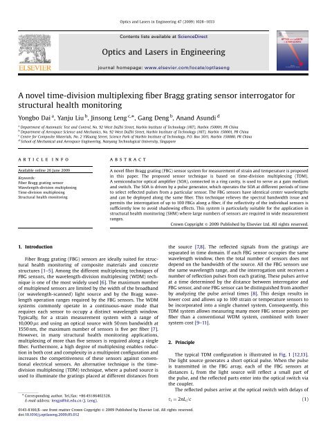
A <strong>novel</strong> <strong>time</strong>-<strong>division</strong> <strong>multiplexing</strong> <strong>fiber</strong> <strong>Bragg</strong> <strong>grating</strong> <strong>sensor</strong> interrogator for<br />
structural health monitoring<br />
Yongbo Dai a , Yanju Liu b , Jinsong Leng c, , Gang Deng b , Anand Asundi d<br />
a Department of Automatic Test and Control, No. 92 West DaZhi Street, Harbin Institute of Technology (HIT), Harbin 150001, PR China<br />
b Department of Aerospace Science and Mechanics, No. 92 West DaZhi Street, Harbin Institute of Technology (HIT), Harbin 150001, PR China<br />
c Centre for Composite Materials, No. 2 YiKuang Street, Science Park of Harbin Institute of Technology, P.O. Box 3011, Harbin 150080, PR China<br />
d School of Mechanical and Aerospace Engineering, Nanyang Technological University, Singapore<br />
article info<br />
Available online 26 June 2009<br />
Keywords:<br />
Fiber <strong>Bragg</strong> <strong>grating</strong> <strong>sensor</strong><br />
Wavelength-<strong>division</strong> <strong>multiplexing</strong><br />
Time-<strong>division</strong> <strong>multiplexing</strong><br />
Structural health monitoring<br />
abstract<br />
A <strong>novel</strong> <strong>fiber</strong> <strong>Bragg</strong> <strong>grating</strong> (FBG) <strong>sensor</strong> system for measurement of strain and temperature is proposed<br />
in this paper. The proposed <strong>sensor</strong> technique is based on <strong>time</strong>-<strong>division</strong> <strong>multiplexing</strong> (TDM).<br />
A semiconductor optical amplifier (SOA), connected in a ring cavity, is used to serve as a gain medium<br />
and switch. The SOA is driven by a pulse generator, which operates the SOA at different periods of <strong>time</strong><br />
to select reflected pulses from a particular <strong>sensor</strong>. The FBG <strong>sensor</strong>s have identical center wavelengths<br />
and can be deployed along the same <strong>fiber</strong>. This technique relieves the spectral bandwidth issue and<br />
permits the interrogation of up to 100 FBGs along a <strong>fiber</strong>, if the reflectivity of the individual <strong>sensor</strong>s is<br />
sufficiently low to avoid shadowing effects. This system is particularly suitable for the application in<br />
structural health monitoring (SHM) where large numbers of <strong>sensor</strong>s are required in wide measurement<br />
ranges.<br />
Crown Copyright & 2009 Published by Elsevier Ltd. All rights reserved.<br />
1. Introduction<br />
Fiber <strong>Bragg</strong> <strong>grating</strong> (FBG) <strong>sensor</strong>s are ideally suited for structural<br />
health monitoring of composite materials and concrete<br />
structures [1–5]. Among the different <strong>multiplexing</strong> techniques of<br />
FBG <strong>sensor</strong>s, the wavelength-<strong>division</strong> <strong>multiplexing</strong> (WDM) technique<br />
is one of the most widely used [6]. The maximum number<br />
of multiplexed <strong>sensor</strong>s are limited by the width of the broadband<br />
(or wavelength-scanned) light source and by the <strong>Bragg</strong> wavelength<br />
operation ranges required by the FBG <strong>sensor</strong>s. The WDM<br />
systems commonly operate in a continuous-wave mode that<br />
requires each <strong>sensor</strong> to occupy a distinct wavelength window.<br />
Typically, for a strain measurement system with a range of<br />
10,000 me and using an optical source with 50 nm bandwidth at<br />
1550 nm, the maximum number of <strong>sensor</strong>s is five per <strong>fiber</strong> [7].<br />
However, in many structural health monitoring applications,<br />
<strong>multiplexing</strong> of more than five <strong>sensor</strong>s is required along a single<br />
<strong>fiber</strong>. Furthermore, a high degree of <strong>multiplexing</strong> enables reduction<br />
in both cost and complexity in a multipoint configuration and<br />
increases the competitiveness of these <strong>sensor</strong>s against conventional<br />
electrical <strong>sensor</strong>s. An alternative technique is the <strong>time</strong><strong>division</strong><br />
<strong>multiplexing</strong> (TDM) technique, where a pulsed source is<br />
used to illuminate the <strong>grating</strong>s placed at different distances from<br />
Corresponding author. Tel./fax: +86 45186402328.<br />
E-mail address: lengjs@hit.edu.cn (J. Leng).<br />
the source [7,8]. The reflected signals from the <strong>grating</strong>s are<br />
separated in <strong>time</strong> domain. If each FBG <strong>sensor</strong> occupies the same<br />
wavelength window, then the total number of <strong>sensor</strong>s does not<br />
depend on the bandwidth of the source. All the FBG <strong>sensor</strong>s use<br />
the same wavelength range, and the interrogation unit receives a<br />
number of reflection pulses from each <strong>grating</strong>. These pulses arrive<br />
at a <strong>time</strong> determined by the distance between interrogator and<br />
FBG <strong>sensor</strong>, and one FBG <strong>sensor</strong> can be distinguished from another<br />
by analyzing the pulse arrival <strong>time</strong>s [8]. This design results in<br />
lower cost and allows up to 100 strain or temperature <strong>sensor</strong>s to<br />
be incorporated into a single channel system. Consequently, this<br />
TDM system allows measuring many more FBG <strong>sensor</strong> points per<br />
<strong>fiber</strong> than a conventional WDM system, combined with lower<br />
system cost [9–11].<br />
2. Principle<br />
The typical TDM configuration is illustrated in Fig. 1 [12,13].<br />
The light source generates a short optical pulse. When the pulse<br />
is transmitted in the FBG array, each of the FBG <strong>sensor</strong>s at<br />
distances L i from the light source will reflect a small part of<br />
the pulse, and the reflected parts enter into the optical switch via<br />
the coupler.<br />
The reflected pulses arrive at the optical switch with delays of<br />
t i ¼ 2nL i =c (1)<br />
0143-8166/$ - see front matter Crown Copyright & 2009 Published by Elsevier Ltd. All rights reserved.<br />
doi:10.1016/j.optlaseng.2009.05.012
ARTICLE IN PRESS<br />
Y. Dai et al. / Optics and Lasers in Engineering 47 (2009) 1028–1033 1029<br />
n is the effective refractive index of optical <strong>fiber</strong> and c the light<br />
velocity in vacuum.<br />
Delay <strong>time</strong> of the optical switch can be adjusted to one of the<br />
FBG <strong>sensor</strong>s, and the reflection spectrum of this particular FBG<br />
<strong>sensor</strong> is measured by the CCD detector. So by changing the delay<br />
<strong>time</strong> any one of the reflected spectra of the FBG array can be<br />
interrogated. However, the interval between the reflected pulses<br />
can become very short for dense <strong>sensor</strong> arrays, and the speed of<br />
the electro-optic switch may not be able to match this.<br />
An alternative to electrical gating is optical gating: an optical<br />
modulator is used to transmit and amplify only reflections for a<br />
single <strong>grating</strong> in the array. Reflections from the isolated <strong>grating</strong><br />
may be integrated over <strong>time</strong> and the wavelength can be extracted.<br />
The TDM system based on optical gating uses a semiconductor<br />
optical amplifier (SOA) as shown in Fig. 2. Typically, a SOA is used<br />
in a continuously-on mode as an amplifier in telecommunications<br />
networks. Here, in the TDM interrogation design, it is driven by a<br />
programmable pulse generator in a short, high-power-pulsed<br />
configuration. When the SOA is first enabled, the drive circuit<br />
causes the SOA to emit a short broadband optical pulse through<br />
the generation of amplified spontaneous emission (ASE). Thus, the<br />
SOA is used as the only light source. The generated broadband<br />
pulse propagates towards the FBG <strong>sensor</strong> array via the <strong>fiber</strong> reel L<br />
to the FBG <strong>sensor</strong>s at distances L i . When the pulse arrives at each<br />
<strong>sensor</strong>, a small reflection begins propagating back towards the<br />
SOA.<br />
At <strong>time</strong> t i (see Eq. (1)), when the reflection from an individual<br />
FBG <strong>sensor</strong> arrives at the SOA, the drive circuit switches on the<br />
SOA again. The weakly reflected signal passes through the SOA<br />
and is amplified. The amplified signal passes through the isolator<br />
and is measured by the optical spectrum analyzer (OSA), the<br />
<strong>sensor</strong> data can be read out. The delay t i of the generator can be<br />
varied, and any FBG <strong>sensor</strong> in the array can be read out. The SOA<br />
can work in a high-speed switch mode with minimum switch<br />
<strong>time</strong> of 1 ns.<br />
The operating principle of the switch is illustrated in Fig. 3a.<br />
First electrical drive pulse is applied to the SOA and an optical<br />
broadband pulse P is generated and launched into the <strong>fiber</strong> <strong>sensor</strong><br />
array. At <strong>time</strong> T1, part of the optical pulse P is reflected by the<br />
<strong>grating</strong> G1 with a spectral pulse of <strong>Bragg</strong> wavelength l1 towards<br />
the SOA. The remainder of the optical pulse P will continue<br />
towards the other <strong>grating</strong>s. At <strong>time</strong> 2T1, a second electrical drive<br />
pulse is applied to the SOA, causing a second optical pulse P to be<br />
generated and launched into the <strong>fiber</strong>. At the same <strong>time</strong>, the first<br />
reflected pulse l1 arrives back at the SOA. Since the SOA is<br />
switched on, it will be transmitted and amplified as described<br />
above. The first reflected pulse l1 will then propagate to the OSA.<br />
However, at this same <strong>time</strong>, the remainder of the first optical<br />
pulse P will arrive at the <strong>grating</strong> G2, where a part of it will be<br />
reflected, creating a second reflected spectral pulse at <strong>Bragg</strong><br />
wavelength l2. From <strong>time</strong> 2T1 to 2T1+2Ts, the l1 and l2 pulses<br />
will arrive at the SOA in same order. The on <strong>time</strong> of the SOA is T w<br />
and the interval between the optical pulses l1 and l2 is2Ts.<br />
If the width T w of the pulses is more than the interval 2Ts, like<br />
the red inset in Fig. 3b, then the OSA cannot distinguish l1 from<br />
l2. So, in this TDM system, the width of the pulses should be less<br />
than the minimal <strong>time</strong> interval between two neighbored <strong>sensor</strong>s.<br />
From the linear arrangement in Fig. 3a, a <strong>novel</strong> ring cavity<br />
configuration has been derived that forms the basis for the<br />
interrogator as illustrated in Fig. 4. The optical loop includes a<br />
<strong>fiber</strong> reel L1, an array of low-reflectivity FBG <strong>sensor</strong>s which have<br />
identical mean resonant wavelength, a ring cavity which is<br />
comprised of a semiconductor optical amplifier and couplers 1<br />
and 2. A pulse generator provides a stream of pulses of<br />
programmable period and duration to drive the SOA. When the<br />
electrical drive circuit turns on and causes the SOA to generate a<br />
short broadband optical pulse which emit via the port 1 and 2<br />
of the SOA. The <strong>fiber</strong> reel L1 has a proper length and the<br />
optical pulses emitted from port 1 and 2 arrive at the coupler 2<br />
at the same <strong>time</strong>, then the two optical pulse form a more<br />
SLED<br />
t1 t2 t3 TN<br />
Pulse<br />
generator<br />
Delay <strong>time</strong>s<br />
Electro-optic<br />
switch<br />
CCD line<br />
Diffraction Grating<br />
Fig. 1. Typical combined TDM/WDM FBG interrogator with electro-optic <strong>grating</strong> [12,13].<br />
Pulse<br />
generator<br />
L<br />
OSA Isolator SOA<br />
G1 G2 G3 GN<br />
Fig. 2. Scheme of switched SOA-based TDM FBG interrogator.
ARTICLE IN PRESS<br />
1030<br />
Y. Dai et al. / Optics and Lasers in Engineering 47 (2009) 1028–1033<br />
Pulse<br />
generator<br />
Tw<br />
T<br />
2Ts<br />
λ1<br />
λ2<br />
0<br />
SOA<br />
P<br />
G1 G2 G3 Gn<br />
Ts<br />
TW<br />
TW1<br />
T1<br />
λ1<br />
P<br />
T1+2TS<br />
λ2<br />
2T1<br />
λ1<br />
2T1+2Ts<br />
λ2<br />
2T1+2(n-1)Ts<br />
λn<br />
Fig. 3. (a) Time/position scheme of light pulses emitted from a pulsed SOA and (b) the limit of pulse width in the TDM system of (a).<br />
L1<br />
L2<br />
OSA<br />
20:80<br />
20:80<br />
SOA<br />
coupler1 1 2<br />
coupler2<br />
G1 G2 Gn<br />
Pulse<br />
generator<br />
Fig. 4. Switched-SOA-based ring cavity FBG TDM configuration.<br />
stronger optical pulse and enter the FBG <strong>sensor</strong> array through the<br />
coupler 2.<br />
On reaching each <strong>grating</strong>, part of the pulses will be reflected,<br />
the reflected pulses arrive at the coupler 2 and are split into two<br />
parts: 80% of the pulse arrives at port 2 of the SOA, and the<br />
remainder arrives at port 1 of the SOA. When the SOA is switched<br />
on, the incoming pulses will pass through and be amplified by<br />
over 15 dB, while the other pulses will be absorbed, when the SOA<br />
is switched off. So, we may tune the period of the driving pulse to<br />
equal the round-trip <strong>time</strong> between the SOA and the FBG. The <strong>fiber</strong><br />
reel length L2 (larger than the distances between FBG <strong>sensor</strong>s)<br />
ensures that only one set of reflected signals can propagate in the<br />
cavity at one <strong>time</strong>, and the round-trip <strong>time</strong> of any <strong>sensor</strong> in the<br />
array is not an integer multiple of another <strong>sensor</strong>.<br />
Each of the FBG <strong>sensor</strong>s can be addressed by different periods<br />
of the SOA driving pulse, and unlike the WDM systems this system<br />
does not address the <strong>sensor</strong>s by their mean <strong>Bragg</strong> wavelength.<br />
If the length difference DL of <strong>fiber</strong>s from the two ports of the<br />
SOA to coupler 2 is large, the pulses emitted from the two ports of<br />
the SOA arrive at the coupler 2 at different <strong>time</strong>s (DL ¼ 1m<br />
produce a pulse delay of 5 ns). In the experiment, the length<br />
difference from the two ports to the coupler 2 is much smaller<br />
than 1 m and the width of the pulses is 40 ns, so the delay<br />
between the two pulses remains o1 ns and can be neglected.<br />
An example for measuring the particular <strong>sensor</strong> G i is used to<br />
illustrate how the TDM FBG interrogator works.<br />
When the SOA is first activated by the pulse generator, the<br />
generated ASE pulse simultaneously emits from the two ports of<br />
the SOA, which add together at coupler 2 and propagate towards<br />
the FBG <strong>sensor</strong> array. After <strong>time</strong> T i , which is equal to the roundtrip<br />
<strong>time</strong> between the <strong>sensor</strong> G i and the SOA, the pulse l i reflected<br />
by <strong>sensor</strong> G i is split into l i1 and l i2 by coupler 2 and arrives<br />
simultaneously at the SOA. The pulse generator switches the SOA<br />
on again, allowing l i1 and l i2 to pass be amplified.
ARTICLE IN PRESS<br />
Y. Dai et al. / Optics and Lasers in Engineering 47 (2009) 1028–1033 1031<br />
Because the total power of the SOA is constant and has the<br />
input signals l i1 and l i2 , the optical pulse emitted from the two<br />
ports of the SOA includes broadband ASE background and the<br />
amplified narrow <strong>sensor</strong> signal. The SOA is driven at the period of<br />
T i , the pulse l i reflected by <strong>sensor</strong> G i will travel through the SOA<br />
repeatedly, and the power of signal l i will increase and the ASE<br />
background will decrease. After approximately five cycles, the<br />
system reaches equilibrium. The loss in the cavity equals the gain<br />
provided by the SOA. After this short <strong>time</strong> (typically a few ms), the<br />
optical signal in the cavity will consist largely of a narrow band<br />
peak. The output signal leaving the ring cavity contains only a<br />
single <strong>sensor</strong> signal and can be extracted using a wavelength<br />
demodulator.<br />
Changing the <strong>time</strong> T i and repeating the above process, the<br />
system can measure any of the FBG <strong>sensor</strong>s along the <strong>fiber</strong>.<br />
3. Estimation of error signal caused by multiple reflections<br />
Power<br />
0.05<br />
0.04<br />
0.03<br />
0.02<br />
0.01<br />
0.00<br />
Reflectivity<br />
20 40 60 80<br />
Number (n)<br />
0.05<br />
0.04<br />
0.03<br />
0.02<br />
0.01<br />
100<br />
When the reflected pulse propagates towards the SOA, part of<br />
it can be reflected by FBGs of same <strong>Bragg</strong> wavelength. Fig. 5 shows<br />
the multiple reflections at the FBGs. Such multiple reflections may<br />
cause cross talk. Assuming the reflectivity of FBG is constant,<br />
a and the power of the source is unity, the reflected pulses by G1,<br />
G2, and G3 are shown in Eq. (2)<br />
P 1 ¼ a<br />
P 2 ¼ að1 aÞ 2<br />
P 3 ¼ að1 aÞ 4 (2)<br />
The reflected pulse P 2 will be partially reflected by G1 and<br />
reflected again by G2 to form pulse P 21 . Fig. 5 shows that the P 3<br />
and P 21 will arrive at the SOA at the same <strong>time</strong>. The signals P 3 and<br />
P 21 may be described by the following equations:<br />
P 21 ¼ a 3 ð1 aÞ 2<br />
P 3 =P 21 ¼ð1 aÞ 2 =a 2 (3)<br />
Consider a numerical example, assuming an upper limit for<br />
reflectivity a ¼ 5%. Then we obtain the relation P 3 /P 21 ¼ 361, i.e.,<br />
P 3 is much higher than P 21 , and hence P 21 can be neglected. Using<br />
low-reflectivity FBGs is necessary for <strong>multiplexing</strong> a high number<br />
of <strong>sensor</strong>s to avoid multiple reflection interference.<br />
The reflected power of the FBG at different reflectivity and<br />
number of <strong>sensor</strong>s is shown in Fig. 6. Based on Eq. (2), we can get<br />
the formula<br />
P n ¼ að1 aÞ 2ðn 1Þ (4)<br />
Eq. (4) indicates that the power can be changed by the<br />
reflectivity and the number of the <strong>sensor</strong>s. Fig. 6 shows the<br />
relation between the power and the number of the <strong>sensor</strong>s for<br />
five different reflectivities, illustrating a decrease in power with<br />
increasing number of the <strong>sensor</strong>s. The power decreases sharply at<br />
a reflectivity of 0.05 (higher shadowing) and slowly at a<br />
reflectivity of 0.01. Using 100 <strong>sensor</strong>s, the power almost<br />
decrease to zero at a reflectivity of 0.05, while the power is still<br />
enough to be measured at a reflectivity of 0.01. Beside such simple<br />
power balance, stronger limitations exist by partly shadowing of<br />
P2<br />
P3<br />
P21<br />
G1 G2 G3<br />
Fig. 5. Multiple reflections at FBG <strong>sensor</strong>s of (almost) equal <strong>Bragg</strong> wavelength.<br />
Fig. 6. Reflected power of large number of <strong>sensor</strong>s at different reflectivity.<br />
<strong>sensor</strong> spectra, with consequent deformation of the received<br />
spectrum and erroneous results of <strong>Bragg</strong> wavelength<br />
measurement. For 100 FBG <strong>sensor</strong>s, maximum reflectivity<br />
should be 0.04 [9]. Consequently, low reflectivity of the FBG<br />
<strong>sensor</strong>s is necessary for the TDM system.<br />
4. Experiments<br />
The experimental device used to evaluate the ring cavity<br />
approach is shown in Fig. 7. Three <strong>sensor</strong>s were put into beaker<br />
filled by water and the temperature difference was monitored<br />
using the TDM system. The SOA was driven by the programmable<br />
pulse generator circuit, the Agilent 33220A that uses a direct<br />
digital synthesis (DDS) technology to accurately tune the<br />
frequency and width of the pulse. The <strong>fiber</strong> reel L2 consisted of<br />
approximately 2000 m of single mode telecommunications <strong>fiber</strong>,<br />
providing a 9780 ns delay for optical pulse. The system was tested<br />
with an array of 3 FBGs having nearly identical <strong>Bragg</strong> wavelengths<br />
of 1550 nm and reflectivity of 5%, the length of the <strong>fiber</strong> LD is 5 m<br />
and is used to separate each FBG. To evaluate the level of <strong>sensor</strong><br />
isolation, the wavelength of each <strong>grating</strong> was partially offset by<br />
using different temperature water, based on the FBG knowledge,<br />
the wavelength of G1, G2, and G3 is different, we can distinguish<br />
the position of the <strong>grating</strong> by the shift of wavelength.<br />
The length of the <strong>fiber</strong> L2 is 2000 m and the round-trip <strong>time</strong><br />
between the SOA and the first FBG is 19.56 ms, so the frequency of<br />
the pulse generator should be close to 51 kHz. The <strong>time</strong> interval<br />
of the reflected optical pulses by the FBGs is 50 ns and the width<br />
of the drive pulse is set to 40 ns to separate each reflected optical<br />
pulse. In this experiment, taking into account that the <strong>grating</strong>s<br />
have an identical central wavelength, the FBGs were placed in<br />
ranging in temperatures from 40 1C (hot water), to 20 1C (normal<br />
water), and to 0 1C (ice water), respectively. We reduce the<br />
frequency gradually from 51 to 50.11, 49.99, 49.87 kHz, to<br />
sequentially address <strong>grating</strong>s G1,G2, and G3, respectively. Fig. 8<br />
shows the recordings taken using the OSA when the pulse<br />
generator was sequentially adjusted to address the 3 FBGs in<br />
turn. Because of difference in water temperature, the central<br />
wavelength shows an obvious shift, but no measurable cross talk.<br />
The results show that the FBG <strong>sensor</strong>s provide an extremely<br />
repeatable signal profile with a peak power of 46 dBm, a<br />
background level of 66 dBm, and an optical signal-tobackground-noise<br />
level of 20 dB. In reference [8], the author’s
ARTICLE IN PRESS<br />
1032<br />
Y. Dai et al. / Optics and Lasers in Engineering 47 (2009) 1028–1033<br />
PC<br />
pulse generator<br />
L2<br />
Wavelength<br />
measuring module<br />
SOA Ring Cavity<br />
40°C 20°C 0°C<br />
LD<br />
LD<br />
G3<br />
G2<br />
G1<br />
Fig. 7. Experimental TDM interrogator of 3 FBG <strong>sensor</strong>s.<br />
-40<br />
-45<br />
G1<br />
G2<br />
G3<br />
1550.60<br />
1550.55<br />
wavelength<br />
Linear Fit of wavelength<br />
Y=0.9997X+1550.232<br />
1550.50<br />
power (dBm)<br />
-50<br />
-55<br />
-60<br />
wavelength (nm)<br />
1550.45<br />
1550.40<br />
1550.35<br />
1550.30<br />
-65<br />
1550.25<br />
-70<br />
1548<br />
1549 1550 1551 1552 1553<br />
wavelength (nm)<br />
Fig. 8. Optical spectra obtained from 3 FBGs G1yG3, kept at different<br />
temperatures 0, 20, and 40 1C, respectively.<br />
1550.20<br />
20<br />
25 30 35 40 45 50 55 60 65<br />
temperature (°C)<br />
Fig. 9. Temperature characteristic of the <strong>Bragg</strong> wavelength, with slope of 10.0 pm/<br />
K at mean <strong>Bragg</strong> wavelength of 1550.4 nm.<br />
system can obtain high-quality signal with an average power of<br />
24 dBm, because of the length of the optical <strong>fiber</strong> is 220 m and<br />
the operating frequency of SOA is near 1 MHz, in this experiment<br />
the operating frequency of SOA is near 50 kHz, so in the same <strong>time</strong><br />
the current system measures fewer pulses and the average power<br />
is lower.<br />
The data we measured is average power but not instantaneous<br />
power, the signal-to-background-noise level is 30 dB. These levels<br />
of performance are excellent for the TDM system.<br />
In order to evaluate the linearity of the TDM system, FBG2 was<br />
placed in a beaker of water whose temperature varied from 24 to<br />
60 1C and measured using a temperature <strong>sensor</strong>. The temperature<br />
increase results in a wavelength change from 1550.232 to<br />
1550.593 nm. The results shown in Fig. 9 indicate a good linear<br />
relationship between wavelength and temperature, with a<br />
coefficient of 10.0 pm/1C. This result agrees with the thermooptic<br />
coefficient of the <strong>fiber</strong>. This experiment shows than the<br />
interrogator has good linearity and the precision is comparable to<br />
the WDM system.<br />
5. Conclusions<br />
We have demonstrated a <strong>novel</strong> FBG <strong>sensor</strong> system based on<br />
ring cavity configuration using TDM to demultiplex up to 100<br />
FBGs in one <strong>fiber</strong>. The ring cavity configuration can capture and<br />
amplify the weak <strong>sensor</strong> signal so that the demodulator can<br />
measure FBGs with low reflectivity. Estimations show negligible<br />
cross talk. The low component count and low loss features of the<br />
system improve the power and extinction ratio of the sensing<br />
signals significant. This system is ideal for implementing large
ARTICLE IN PRESS<br />
Y. Dai et al. / Optics and Lasers in Engineering 47 (2009) 1028–1033 1033<br />
numbers of FBG <strong>sensor</strong>s for structural health monitoring (SHM)<br />
applications.<br />
References<br />
[1] Leng JS, Asundi A. Structural health monitoring of smart composite materials<br />
by using the extrinsic Fabry–Perot interferometer and <strong>fiber</strong> <strong>Bragg</strong> <strong>grating</strong><br />
<strong>sensor</strong>s. Sensors and Actuators A 2003;103:330–40.<br />
[2] Leng JS, Asundi A. Real-<strong>time</strong> cure monitoring of smart composite materials<br />
using extrinsic Fabry–Perot interferometer and fibre <strong>Bragg</strong> <strong>grating</strong> <strong>sensor</strong>s.<br />
Smart Materials and Structures 2002;11:249–55.<br />
[3] Merzbacher CI, Kersey AD, Friebele EJ. Fibre optic <strong>sensor</strong>s in concrete<br />
structures: a review. Smart materials and structures 1996;5:196–208.<br />
[4] Leng JS, et al. Structural NDE of concrete structures using protected EFPI and<br />
FBG Sensors. Sensors and Actuator A 2006;l26:340–7.<br />
[5] Leng JS, et al. Structural health monitoring of concrete cylinder using protected<br />
fibre optic <strong>sensor</strong>s. Smart Materials and Structures 2006;15(2):302–8.<br />
[6] Berkoff TA, Davis MA, Bellemore DG, Kersey AD, Williams GM, Putnam MA.<br />
Hybrid <strong>time</strong> and wavelength-<strong>division</strong> multiplexed fibre <strong>grating</strong> array. Proc<br />
SPIE 1995;2444:288–90.<br />
[7] Lloyd GD, Everall LA, Sugden K, Bennion I. Resonant cavity <strong>time</strong>-<strong>division</strong>multiplexed<br />
<strong>fiber</strong> <strong>Bragg</strong> <strong>grating</strong> <strong>sensor</strong> interrogator. IEEE Photon Technol Lett<br />
2004;16(10):2323–5 (October 2004).<br />
[8] Chung WH, Tam HY, Wai PKA, Khandelwal A. Time- and wavelength-<strong>division</strong><br />
<strong>multiplexing</strong> of FBG <strong>sensor</strong>s using a semiconductor optical amplifier in<br />
ring cavity configuration. IEEE Photon Technol Lett 2005;17(12):2709–11<br />
(December 2005).<br />
[9] Cooper DJ, Coroy T, Smith PWE. Time-<strong>division</strong> <strong>multiplexing</strong> of large serial<br />
<strong>fiber</strong>-optic <strong>Bragg</strong> <strong>grating</strong> <strong>sensor</strong> arrays. Appl Opt 2001;40:2643–54.<br />
[10] Lloyd GD, Everall Lorna A, Sugden Kate, Bennion Ian. A high-performance<br />
miniaturized <strong>time</strong>-<strong>division</strong> multiplexed <strong>sensor</strong> system for remote structural<br />
health monitoring. Proc SPIE 2004;5459:145–55.<br />
[11] Lloyd GD, Bennion I, Everall LA, Sugden K, Novel resonant cavity TDM<br />
demodulation scheme for FBG sensing. In: Proc CLEO, San Francisco, CA, Paper<br />
CWD4, May 2004.<br />
[12] Askins CG, Putnam MA, Optical spectrometer with improved geometry and<br />
data processing for monitoring <strong>fiber</strong> optic <strong>Bragg</strong> <strong>grating</strong>s, US patent<br />
6,233,373, 2001.<br />
[13] Ecke W, Nunes LCS, Valente LCG, Schroeder K, Chojetzki C, Willsch R, OTDR<br />
Multiplexed High-Birefringent Fiber Grating Sensor Network for Transversal<br />
Strain and Optochemical Monitoring. In: Proc. sixteenth int conf opt Fiber<br />
Sensors, IEICE Japan, ISBN 4-89114-036-4, 2003 pp. 548–551.