ABB i-bus® EIB Universal Interfaces US/U 4.2 US/U ... - WindowMaster
ABB i-bus® EIB Universal Interfaces US/U 4.2 US/U ... - WindowMaster
ABB i-bus® EIB Universal Interfaces US/U 4.2 US/U ... - WindowMaster

You also want an ePaper? Increase the reach of your titles
YUMPU automatically turns print PDFs into web optimized ePapers that Google loves.
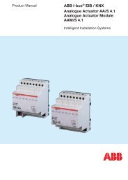
Product Manual<br />
<strong>ABB</strong> i-bus ® <strong>EIB</strong><br />
<strong>Universal</strong> <strong>Interfaces</strong><br />
<strong>US</strong>/U <strong>4.2</strong><br />
<strong>US</strong>/U 2.2<br />
Intelligent Installation Systems<br />
Intelligent and<br />
limitless
Contents<br />
Page<br />
1 General . . . . . . . . . . . . . . . . . . . . . . . . . . . . . . . . . . . . . . . . . . . . . 3<br />
1.1 Product and functional overview . . . . . . . . . . . . . . . . . . . . . . . . . . 3<br />
2 Device technology . . . . . . . . . . . . . . . . . . . . . . . . . . . . . . . . . . . . 4<br />
2.1 Technical data . . . . . . . . . . . . . . . . . . . . . . . . . . . . . . . . . . . . . . . . 4<br />
2.2 Device connection . . . . . . . . . . . . . . . . . . . . . . . . . . . . . . . . . . . . . 5<br />
2.3 Description of the inputs and outputs . . . . . . . . . . . . . . . . . . . . . . 6<br />
2.4 Assembly and installation . . . . . . . . . . . . . . . . . . . . . . . . . . . . . . . 6<br />
3 Function and operation . . . . . . . . . . . . . . . . . . . . . . . . . . . . . . . 7<br />
4 Project design and programming . . . . . . . . . . . . . . . . . . . . . . . 8<br />
4.1 Overview of the functions . . . . . . . . . . . . . . . . . . . . . . . . . . . . . . . 8<br />
<strong>4.2</strong> Overview of the communication objects . . . . . . . . . . . . . . . . . . . . 9<br />
4.3 General functions . . . . . . . . . . . . . . . . . . . . . . . . . . . . . . . . . . . . . 9<br />
4.3.1 General parameters . . . . . . . . . . . . . . . . . . . . . . . . . . . . . 9<br />
4.3.2 General communication objects . . . . . . . . . . . . . . . . . . . . 10<br />
4.4 Function: “Switch sensor” . . . . . . . . . . . . . . . . . . . . . . . . . . . . . . . 11<br />
4.4.1 Parameters . . . . . . . . . . . . . . . . . . . . . . . . . . . . . . . . . . . . 11<br />
4.<strong>4.2</strong> Communication objects . . . . . . . . . . . . . . . . . . . . . . . . . . 13<br />
4.5 Function: “Switch/dimming sensor” . . . . . . . . . . . . . . . . . . . . . . . . 14<br />
4.5.1 Parameters . . . . . . . . . . . . . . . . . . . . . . . . . . . . . . . . . . . . 14<br />
4.5.2 Communication objects . . . . . . . . . . . . . . . . . . . . . . . . . . 15<br />
4.6 Function: “Shutter sensor” . . . . . . . . . . . . . . . . . . . . . . . . . . . . . . . 17<br />
4.6.1 Parameters . . . . . . . . . . . . . . . . . . . . . . . . . . . . . . . . . . . . 17<br />
4.6.2 Communication objects . . . . . . . . . . . . . . . . . . . . . . . . . . 19<br />
4.7 Function: “Value / forced operation” . . . . . . . . . . . . . . . . . . . . . . . 20<br />
4.7.1 Parameters . . . . . . . . . . . . . . . . . . . . . . . . . . . . . . . . . . . . 20<br />
4.7.2 Communication objects . . . . . . . . . . . . . . . . . . . . . . . . . . 21<br />
4.8 Function: “Control scene” . . . . . . . . . . . . . . . . . . . . . . . . . . . . . . . 23<br />
4.8.1 Parameters . . . . . . . . . . . . . . . . . . . . . . . . . . . . . . . . . . . . 23<br />
4.8.2 Communication objects . . . . . . . . . . . . . . . . . . . . . . . . . . 25<br />
4.9 Function: “Control electronic relay (heating actuator)” . . . . . . . . . 27<br />
4.9.1 Parameters . . . . . . . . . . . . . . . . . . . . . . . . . . . . . . . . . . . . 27<br />
4.9.2 Communication objects . . . . . . . . . . . . . . . . . . . . . . . . . . 29<br />
4.10 Function: “Control LED” . . . . . . . . . . . . . . . . . . . . . . . . . . . . . . . . . 31<br />
4.10.1 Parameters . . . . . . . . . . . . . . . . . . . . . . . . . . . . . . . . . . . . 31<br />
4.10.2 Communication objects . . . . . . . . . . . . . . . . . . . . . . . . . . 32<br />
4.11 Function: “Switching sequence” . . . . . . . . . . . . . . . . . . . . . . . . . . 33<br />
4.11.1 Parameters . . . . . . . . . . . . . . . . . . . . . . . . . . . . . . . . . . . . 33<br />
4.11.2 Communication objects . . . . . . . . . . . . . . . . . . . . . . . . . . 34<br />
4.12 Function: “Push button with multiple operation” . . . . . . . . . . . . . . 35<br />
4.12.1 Parameters . . . . . . . . . . . . . . . . . . . . . . . . . . . . . . . . . . . . 35<br />
4.12.2 Communication objects . . . . . . . . . . . . . . . . . . . . . . . . . . 36<br />
4.13 Function: “Counter” . . . . . . . . . . . . . . . . . . . . . . . . . . . . . . . . . . . . 37<br />
4.13.1 Parameters . . . . . . . . . . . . . . . . . . . . . . . . . . . . . . . . . . . . 37<br />
4.13.2 Communication objects . . . . . . . . . . . . . . . . . . . . . . . . . . 39<br />
4.14 Programming . . . . . . . . . . . . . . . . . . . . . . . . . . . . . . . . . . . . . . . . . 40<br />
1
Contents<br />
Seite<br />
5 Special functions . . . . . . . . . . . . . . . . . . . . . . . . . . . . . . . . . . . . . 41<br />
5.1 Debounce time and minimum operation time . . . . . . . . . . . . . . . . 41<br />
5.2 Limit telegram rate . . . . . . . . . . . . . . . . . . . . . . . . . . . . . . . . . . . . . 42<br />
5.3 Cyclical sending . . . . . . . . . . . . . . . . . . . . . . . . . . . . . . . . . . . . . . . 42<br />
5.4 Dimming . . . . . . . . . . . . . . . . . . . . . . . . . . . . . . . . . . . . . . . . . . . . . 42<br />
5.5 Scene control . . . . . . . . . . . . . . . . . . . . . . . . . . . . . . . . . . . . . . . . . 43<br />
5.6 Control of electronic relay (heating actuator) . . . . . . . . . . . . . . . . 43<br />
5.7 Switching sequences . . . . . . . . . . . . . . . . . . . . . . . . . . . . . . . . . . . 45<br />
5.8 Pulse counter . . . . . . . . . . . . . . . . . . . . . . . . . . . . . . . . . . . . . . . . . 46<br />
5.9 Behaviour during bus voltage failure . . . . . . . . . . . . . . . . . . . . . . . 47<br />
5.10 Behaviour after bus voltage recovery . . . . . . . . . . . . . . . . . . . . . . 47<br />
6 Planning and application . . . . . . . . . . . . . . . . . . . . . . . . . . . . . . 49<br />
6.1 1 push button operation with central function (switch lamp) . . . . . 49<br />
6.2 Operation of dimmable lighting . . . . . . . . . . . . . . . . . . . . . . . . . . . 50<br />
6.3 Operation of shutters . . . . . . . . . . . . . . . . . . . . . . . . . . . . . . . . . . . 51<br />
6.4 Controlling scenes . . . . . . . . . . . . . . . . . . . . . . . . . . . . . . . . . . . . . 53<br />
6.5 Controlling a heating valve . . . . . . . . . . . . . . . . . . . . . . . . . . . . . . 55<br />
6.6 Switching the lighting in sequence . . . . . . . . . . . . . . . . . . . . . . . . 57<br />
6.7 Switching the lighting via multiple push button operation . . . . . . . 59<br />
6.8 Counting energy values . . . . . . . . . . . . . . . . . . . . . . . . . . . . . . . . . 60<br />
7 Appendix . . . . . . . . . . . . . . . . . . . . . . . . . . . . . . . . . . . . . . . . . . . 61<br />
7.1 Table of grey code . . . . . . . . . . . . . . . . . . . . . . . . . . . . . . . . . . . . . 61<br />
7.2 Ordering information . . . . . . . . . . . . . . . . . . . . . . . . . . . . . . . . . . . 62<br />
This manual describes the function of the universal interfaces <strong>US</strong>/U 2.2 and<br />
<strong>US</strong>/U <strong>4.2</strong> with the application program “Binary Input Display Heat xf/1”.<br />
Subject to technical changes. Errors excepted<br />
Exclusion of liability:<br />
Despite checking that the contents of this document correspond to the hardware<br />
and software, deviations cannot be ruled out completely. We therefore<br />
cannot accept liability for this. Any necessary corrections will be integrated in<br />
new versions of the manual.<br />
Please tell us about any suggestions for improvement you may have.<br />
2
<strong>ABB</strong> i-bus ® <strong>EIB</strong><br />
1 General<br />
SK 0093 B02<br />
<strong>Universal</strong> <strong>Interfaces</strong><br />
<strong>US</strong>/U 2.2, GH Q631 0074 R0111<br />
<strong>US</strong>/U <strong>4.2</strong>, GH Q631 0070 R0111<br />
The functions implemented in modern buildings with <strong>ABB</strong> i-bus ® <strong>EIB</strong> should<br />
be both simple to operate and intuitive. At the same time, clear and userfriendly<br />
operation is extremely important to the value of a building installation.<br />
The universal interfaces <strong>US</strong>/U 2.2 and <strong>US</strong>/U <strong>4.2</strong> meet individual requirements<br />
in both functional buildings and the residential sector. A variety of<br />
application possibilities are thus available to the planner of the system as<br />
regards the implementation of functions.<br />
This manual provides technical information about the device as well as its<br />
assembly and programming. The last section contains application examples<br />
for its effective use on site.<br />
<strong>US</strong>/U <strong>4.2</strong><br />
1.1 Product and functional<br />
overview<br />
The universal interfaces <strong>US</strong>/U 2.2 (two channels) and <strong>US</strong>/U <strong>4.2</strong> (four channels)<br />
are used as an interface for the convenient operation of <strong>ABB</strong> i-bus ® <strong>EIB</strong> installations<br />
via conventional push buttons/switches or for reading out technical<br />
binary signals. They also enable the control of LEDs as well as the electronic<br />
relay ER/U 1.1 for controlling electrothermal valve drives.<br />
The extremely compact design enables the device to be inserted in a conventional<br />
60 mm wiring box e.g. behind a conventional push button or switch.<br />
The devices stand out due to their functionality which is extremely extensive<br />
but comprehensible and enables the devices to be used in a wide variety<br />
of application areas. The following list provides an overview:<br />
●<br />
●<br />
●<br />
●<br />
●<br />
●<br />
●<br />
●<br />
●<br />
Switching and dimming of the lighting (also 1 button operation)<br />
Operation of blinds and shutters (also 1 button operation)<br />
Sending of values e.g. temperature values<br />
Control and storing of lightscenes<br />
Triggering an electronic relay for controlling an electrothermal drive<br />
mechanism for heating valves<br />
Triggering an LED (with flashing function and time restriction) for reporting<br />
an operation<br />
Operation of various loads by multiple push button actions<br />
Operation of several loads in a fixed switching sequence<br />
Counting of impulses and push button operations<br />
● Reading out of technical contacts (e.g. relays)<br />
Each channel of a device can adopt any of the functions described above.<br />
3
<strong>ABB</strong> i-bus ® <strong>EIB</strong><br />
2 Device technology<br />
<strong>Universal</strong> <strong>Interfaces</strong><br />
<strong>US</strong>/U 2.2, GH Q631 0074 R0111<br />
<strong>US</strong>/U <strong>4.2</strong>, GH Q631 0070 R0111<br />
This section outlines the device functions of the universal interfaces <strong>US</strong>/U 2.2<br />
and <strong>US</strong>/U <strong>4.2</strong>. The device has two (<strong>US</strong>/U 2.2) or four (<strong>US</strong>/U <strong>4.2</strong>) channels<br />
which can be configured as inputs or outputs with the <strong>EIB</strong> Tool Software<br />
ETS2 V1.2a (or higher).<br />
Using the colour-coded connecting cables, it is possible to connect conventional<br />
push buttons, floating contacts, light-emitting diodes (LEDs) or electronic<br />
relays ER/U 1.1. Series resistors for the operation of LEDs are integrated<br />
into the device. The contact scanning voltage and the supply voltage for<br />
LEDs or electronic relay are made available by the device.<br />
The bus connection is carried out via the bus connecting terminal supplied.<br />
2.1 Technical data<br />
Power supply: – Bus voltage via the <strong>ABB</strong> i-bus ® <strong>EIB</strong><br />
Power consumption < approx. 10 mA<br />
Inputs/outputs: – Number 2 for <strong>US</strong>/U 2.2<br />
4 for <strong>US</strong>/U <strong>4.2</strong><br />
Can be individually parameterised<br />
as inputs or outputs<br />
– Permitted cable length ≤ 10 m<br />
Input: – Scanning voltage 20 V DC<br />
– Input current 0.5 mA<br />
Output: – Output voltage 5 V DC<br />
– Output current max. 2 mA, limited via series resistor<br />
of 1.5 kΩ<br />
– Safety Short-circuit-proof, overload<br />
protection, reverse voltage protection<br />
Operating and display elements:<br />
– (Red) LED and push button For assigning the physical address<br />
Connections: – Inputs/outputs 4 cables for <strong>US</strong>/U 2.2<br />
6 cables for <strong>US</strong>/U <strong>4.2</strong><br />
approx. 30 cm long, can be extended to max. 10 m<br />
– <strong>ABB</strong> i-bus ® <strong>EIB</strong> via bus connecting terminal,<br />
with supply<br />
Ambient temperature range: – Operation – 5 °C ... 45 °C<br />
– Storage – 25 °C ... 55 °C<br />
– Transport – 25 °C ... 70 °C<br />
Miscellaneous: Type of protection IP 20 (EN 60529)<br />
when installed<br />
Protection class<br />
III<br />
CE norm<br />
in accordance with the EMC<br />
guideline and the low voltage guideline<br />
Certification<br />
<strong>EIB</strong>-certified<br />
Mounting<br />
in switch box, 60 mm<br />
Dimensions (W x H x D) 39 x 40 x 12 mm<br />
Weight<br />
0.05 kg<br />
4
<strong>ABB</strong> i-bus ® <strong>EIB</strong><br />
2.2 Device connection<br />
<strong>Universal</strong> <strong>Interfaces</strong><br />
<strong>US</strong>/U 2.2, GH Q631 0074 R0111<br />
<strong>US</strong>/U <strong>4.2</strong>, GH Q631 0070 R0111<br />
During operation as an input, the scanned contact is connected between<br />
the grey core and the coloured core.<br />
During operation as an output, the load (LED or electronic relay) is connected<br />
between the black and the coloured core. The coloured core represents<br />
the positive output voltage.<br />
Connection of a floating push button/switch<br />
coloured / farbig<br />
grey / grau<br />
Connection of an electronic relay<br />
coloured / farbig<br />
black /<br />
schwarz<br />
Connection of an LED<br />
coloured / farbig<br />
2 mA<br />
black / schwarz<br />
Note:<br />
When connecting to an S0 impulse output (e.g. an energy<br />
consumption meter), it must be ensured that it is electrically<br />
isolated from the mains. The correct polarity should also be<br />
observed (“+” on the grey core).<br />
5
<strong>ABB</strong> i-bus ® <strong>EIB</strong><br />
2.3 Description of the inputs<br />
and outputs<br />
<strong>Universal</strong> <strong>Interfaces</strong><br />
<strong>US</strong>/U 2.2, GH Q631 0074 R0111<br />
<strong>US</strong>/U <strong>4.2</strong>, GH Q631 0070 R0111<br />
Grey core: Positive scanning voltage<br />
During operation as an input, the grey core makes the positive, pulsed<br />
scanning voltage available.<br />
Coloured core: Control of the channel<br />
During operation as an input, the status of the contact is read out via the<br />
coloured cores.<br />
During operation as an output, the coloured core makes the positive output<br />
voltage available.<br />
The following table allocates the colours to the channels:<br />
brown Channel A<br />
red<br />
Channel B<br />
orange* Channel C<br />
yellow* Channel D<br />
*only for <strong>US</strong>/U <strong>4.2</strong><br />
Black core: Negative reference potential<br />
During operation as an output, the black core makes the negative reference<br />
potential available.<br />
Important:<br />
The inputs and outputs do not have electrical isolation<br />
to the <strong>EIB</strong> bus voltage (SELV). The SELV criteria only enable<br />
the connection of floating contacts with safety separation.<br />
2.4 Assembly and installation<br />
The device can in mounted in any position. Any cores that are not required<br />
must be insulated.<br />
6
<strong>ABB</strong> i-bus ® <strong>EIB</strong><br />
3 Function and<br />
operation<br />
<strong>Universal</strong> <strong>Interfaces</strong><br />
<strong>US</strong>/U 2.2, GH Q631 0074 R0111<br />
<strong>US</strong>/U <strong>4.2</strong>, GH Q631 0070 R0111<br />
This section does not apply.<br />
7
<strong>ABB</strong> i-bus ® <strong>EIB</strong><br />
<strong>Universal</strong> <strong>Interfaces</strong><br />
<strong>US</strong>/U 2.2, GH Q631 0074 R0111<br />
<strong>US</strong>/U <strong>4.2</strong>, GH Q631 0070 R0111<br />
4 Project design and<br />
programming<br />
4.1 Overview of the functions A powerful application program “Binary Input Display Heat 2f/1” (<strong>US</strong>/U 2.2) and<br />
“… 4f/1” (<strong>US</strong>/U <strong>4.2</strong>) is available for the universal interfaces. The programming<br />
requires ETS2 V1.2a or higher.<br />
Application program Number of Max. number of Max. number of<br />
communication objects group addresses associations<br />
Binary Input Display Heat, 2f/1 15 254 254<br />
Binary Input Display Heat, 4f/1 29 254 254<br />
The following functions can be set separately for each input:<br />
Switch sensor<br />
Switch/dimming sensor<br />
Shutter sensor<br />
For switching the lighting or scanning a floating contact<br />
(relay).<br />
Distinction between short/long operation and<br />
cyclical sending of the contact state are possible.<br />
For switching/dimming the lighting.<br />
Start/stop dimming and stepwise dimming, as well as<br />
dimming via a single push button are possible.<br />
For movement/louvre adjustment of a shutter or blind.<br />
Eight present operation modes are possible in total.<br />
Value / Forced operation For sending the values of different data types<br />
(e.g. temperature values).<br />
It is possible to send different values or data types for<br />
short/long operation, possible to activate/deactivate<br />
the forced operation of actuators.<br />
Control scene<br />
For recalling and storing the states of several actuator<br />
groups.<br />
The actuator groups can either be controlled via<br />
max. 5 individual objects or (if supported by the actuators)<br />
via a special 8 bit scene object.<br />
Control of electronic relay For controlling an electrothermal valve drive<br />
(heating actuator) via an electronic relay ER/U 1.1.<br />
The device has the full functionality of a heating actuator.<br />
Control via 2-step controller or continuous controller (PWM),<br />
cyclical valve purging, monitoring of the room thermostat<br />
and forced operation of the valve drive are possible.<br />
Control LED<br />
For controlling a light-emitting diode.<br />
Switching and flashing (with time limit and various flashing<br />
rates) and use as an orientation light are possible.<br />
Switching sequence For the operation of several actuator groups in<br />
(“latching relay”)<br />
a preselected sequence.<br />
Push button with<br />
For triggering various functions depending on the<br />
multiple operation frequency of the operation.<br />
A long operation can also be detected and a function can<br />
be triggered.<br />
Counter<br />
For counting input pulses.<br />
Various data types of the counter can be set. An additional<br />
intermediate counter enables the counting of e.g. daily<br />
values. Factors/dividers enable various counting rates.<br />
8
<strong>ABB</strong> i-bus ® <strong>EIB</strong><br />
<strong>4.2</strong> Overview of the<br />
communication objects<br />
<strong>Universal</strong> <strong>Interfaces</strong><br />
<strong>US</strong>/U 2.2, GH Q631 0074 R0111<br />
<strong>US</strong>/U <strong>4.2</strong>, GH Q631 0070 R0111<br />
Both the communication objects and the objects are identical for each<br />
channel.<br />
4.3 General functions<br />
Parameters and objects, which apply to the device as a whole, are outlined<br />
in this section.<br />
Parameters and objects which are assigned to each channel, are described<br />
in the following sections using output A as an example.<br />
4.3.1 General parameters<br />
Parameters for the functions which affect the complete device can be set via<br />
the “General” parameter window.<br />
Parameter: “Transmission delay after bus voltage recovery”<br />
The transmission delay determines the period between bus voltage recovery<br />
and the point after which telegrams can be sent. An initialisation period<br />
of approx. 2 seconds for starting the device is included in the transmission<br />
delay.<br />
If objects are read out via the bus during the transmission delay (e.g. from<br />
visualisation terminals), these requests are stored and are likewise answered<br />
once the transmission delay has elapsed.<br />
See section 5.10 for a detailed description of the behaviour on bus voltage<br />
recovery.<br />
Parameter: “ Limit number of telegrams”<br />
In order to check the bus load which is generated by the device, there is a<br />
powerful limit function for telegrams. It is possible to set how many telegrams<br />
can be sent within an adjustable period<br />
(“Max. number of transmitted telegrams within a period”).<br />
Detailed information about the telegram limit function can be obtained under<br />
section 5.2.<br />
9
<strong>ABB</strong> i-bus ® <strong>EIB</strong><br />
<strong>Universal</strong> <strong>Interfaces</strong><br />
<strong>US</strong>/U 2.2, GH Q631 0074 R0111<br />
<strong>US</strong>/U <strong>4.2</strong>, GH Q631 0070 R0111<br />
Parameter: “Transmit object ‘Telegr. valve purge’”<br />
This function is only relevant if one or several channels are used to control<br />
an electronic relay. Regular purging of a heating control valve can prevent<br />
deposits from building up in the valve thereby restricting the valve function.<br />
This is particularly significant during periods when only a few changes are<br />
made to the valve position.<br />
If this parameter is set to “yes”, the object “Telegr. trigger valve purge” is<br />
visible. It is sent at adjustable intervals to start the valve purge<br />
(“Transmit telegram every”) and has the value “1” for the “Period of valve<br />
purge”. The “Valve purge” object of a channel which has been assigned the<br />
function of a heating actuator can be controlled via this object.<br />
4.3.2 General<br />
communication objects<br />
Object “Disable”: 1 bit (EIS 1)<br />
This object is visible for each channel that is operated as an input.<br />
The function of the protective input circuit can be disabled or enabled via<br />
the “Disable” object. A disabled input behaves as if a change in the input<br />
signal has not taken place. The objects of the input remain available.<br />
If the input is disabled during operation, the behaviour is undefined.<br />
When a disabled input is enabled, no telegrams are initially sent on the bus,<br />
even if the status of the input has changed during the blocking. If the input is<br />
operated when it is enabled, it behaves as if the operation had started with<br />
the end of the blocking.<br />
Telegram value “0”: Enable input<br />
“1”: Disable input<br />
Object “Telegr. trigger valve purge”: 1 bit (EIS 1)<br />
This object is visible if the parameter “Transmit object ‘Telegr. valve<br />
purge’” is set to “yes”.<br />
The object is set at regular intervals to the value “1” for an adjustable period<br />
and then reset to “0”.<br />
It can be used for example to trigger a valve purge at regular intervals<br />
(see “Valve purge” object).<br />
After bus voltage recovery, this object sends the value “0” to the bus and the<br />
purge cycle is restarted.<br />
10
<strong>ABB</strong> i-bus ® <strong>EIB</strong><br />
4.4 Function: “Switch sensor”<br />
<strong>Universal</strong> <strong>Interfaces</strong><br />
<strong>US</strong>/U 2.2, GH Q631 0074 R0111<br />
<strong>US</strong>/U <strong>4.2</strong>, GH Q631 0070 R0111<br />
The following parameters and objects are visible if the “Switch sensor”<br />
function has been selected.<br />
4.4.1 Parameters<br />
Parameter: “Distinction between long and short operation”<br />
This parameter sets whether the input distinguishes between a short and<br />
long operation. If “yes” is selected, there is a waiting period after the opening/closing<br />
of the contact to determine whether the operation is long or<br />
short. Only then is a possible reaction triggered.<br />
11
<strong>ABB</strong> i-bus ® <strong>EIB</strong><br />
<strong>Universal</strong> <strong>Interfaces</strong><br />
<strong>US</strong>/U 2.2, GH Q631 0074 R0111<br />
<strong>US</strong>/U <strong>4.2</strong>, GH Q631 0070 R0111<br />
The following drawing clarifies the function:<br />
Without<br />
distinction between<br />
short/long<br />
With<br />
distinction between<br />
short/long<br />
Input signal<br />
T L<br />
Possible reaction<br />
to the input signal<br />
Possible reaction<br />
to the input signal<br />
Diagram 1: Distinction between short/long operation in the “Switch sensor” function<br />
T L is the period after which a long operation is detected.<br />
Parameter: “Cyclic transmission of object ‘Telegr. switch’”<br />
This parameter is visible if there is no distinction between a short and long<br />
operation.<br />
The object “Telegr. switch” can be sent cyclically e.g. to monitor the life signs<br />
of the sensor.<br />
If the parameter value “always” is selected, the object sends cyclically<br />
on the bus, regardless of its value.<br />
If the parameter value “if ‘switch’ = ON” or “if ‘switch’ = OFF” is set,<br />
only the corresponding object value is sent cyclically.<br />
You can receive further information about the topic “Cyclical sending”<br />
in section 5.3.<br />
Parameter: “Reaction on closing the contact” or<br />
“Reaction on opening the contact”<br />
This parameter is visible if there is no distinction between a short and long<br />
operation. It can be set separately for each pulse edge whether the object<br />
value should be “ON, “OFF”, “TOGGLE” or “no reaction”.<br />
If cyclical sending has been parameterised, it is possible to select the option<br />
“terminate cyclic transmission” so that an operation of the input can stop the<br />
cyclical sending without a new object value being sent.<br />
Parameter: “Telegram is repeated every (‘transmission cycle time’)”<br />
This parameter is visible if cyclical sending has been set.<br />
The transmission cycle time describes the interval between two telegrams<br />
that are sent cyclically.<br />
Transmission cycle time = Base x Factor.<br />
Parameter: “Connected contact type”<br />
This parameter is visible if there is no distinction between a short and long<br />
operation.<br />
It is possible to select whether the contact at the input is a normally closed<br />
contact or a normally opened contact.<br />
12
<strong>ABB</strong> i-bus ® <strong>EIB</strong><br />
<strong>Universal</strong> <strong>Interfaces</strong><br />
<strong>US</strong>/U 2.2, GH Q631 0074 R0111<br />
<strong>US</strong>/U <strong>4.2</strong>, GH Q631 0070 R0111<br />
Parameter: “Reaction on short operation” or<br />
“Reaction on long operation”<br />
This parameter is visible if there is no distinction between a short and long<br />
operation.<br />
It can be set for each operation at the input (short or long) how the object<br />
value is changed. The object value is updated as soon as it is established<br />
whether the operation is long or short.<br />
Parameter: “Long operation after”<br />
This parameter is visible if there is a distinction between a short and long<br />
operation. The period T L is defined here, after which an operation is interpreted<br />
as “long”.<br />
T L = Base x Factor.<br />
Parameter: “Number of objects for short/long operation”<br />
This parameter is visible if there is a distinction between a short and long<br />
operation.<br />
To differentiate between short and long operations, it is possible to activate<br />
a further object by setting the parameter value “2 objects” which reacts solely<br />
to long operations.<br />
Parameter: “Transmit object value after bus voltage recovery”<br />
This parameter is only visible if there is no distinction between a short and<br />
long operation.<br />
It can be set whether the current status of the input is sent on the bus (object<br />
“Telegr. switch”) after bus voltage recovery (once the transmission delay has<br />
elapsed).<br />
A value is however only sent on the bus if the value “TOGGLE” has not been<br />
set in either of the two parameters “Reaction on opening/closing the contact”.<br />
If one of the two parameters has the value “TOGGLE”, no values are sent in<br />
general on the bus after bus voltage recovery.<br />
Parameter: “Debounce time / min. operation time”<br />
The debounce prevents unwanted multiple operation of the input e.g. by<br />
bouncing of the contacts. Refer to section 5.1 for the exact function of this<br />
parameter. A minimum operation time can only be set if there is no distinction<br />
between a short and long operation.<br />
4.<strong>4.2</strong> Communication objects<br />
Object: “Telegr. switch”, 1 bit (EIS 1)<br />
According to the parameter setting, it is possible for this object to be switched<br />
on, switched off or toggled via an operation of the input.<br />
If the parameter “Distinction between long and short operation” is set to “yes”<br />
and the parameter “Number of objects for short/long operation” is set to<br />
“2 objects”, two separate objects are made available. The second object is<br />
assigned to long operations.<br />
13
<strong>ABB</strong> i-bus ® <strong>EIB</strong><br />
4.5 Function:<br />
“Switch/dimming sensor”<br />
<strong>Universal</strong> <strong>Interfaces</strong><br />
<strong>US</strong>/U 2.2, GH Q631 0074 R0111<br />
<strong>US</strong>/U <strong>4.2</strong>, GH Q631 0070 R0111<br />
The following section describes all the parameters and objects which are<br />
visible if the input is operated with the function “Switch/dimming sensor”.<br />
The function enables the operation of dimmable lighting. 1 button operation<br />
is also possible.<br />
Further details about the dimming function can be found in section 5.4.<br />
4.5.1 Parameter<br />
Parameter: “Connected contact type”<br />
This parameter defines whether the contact at the input is a normally open<br />
contact or a normally closed contact.<br />
Parameter: “Dimming functionality”<br />
This parameter determines whether the lighting is only dimmed (“Only dimming”)<br />
or whether it should also be switched (“Dimming and switching”).<br />
In this case, the lighting is dimmed via a long operation and switched<br />
via a short operation.<br />
The benefit of the setting “Only dimming” is that there is no distinction between<br />
a short and long operation. The dimming command is therefore carried<br />
out immediately after the push button action; there is no delay to determine<br />
whether the operation is long or short.<br />
Parameter: “Reaction on short operation”<br />
This parameter is visible if the value “Dimming and switching” has been set in<br />
the parameter “Dimming functionality”.A short operation changes the value of<br />
the object “Telegr. switch”.<br />
This parameter sets whether the object “Telegr. switch” is toggled after<br />
a short operation (typically: dimming with 1 button) or only switched on and<br />
off (typically: dimming with 2 buttons).<br />
14
<strong>ABB</strong> i-bus ® <strong>EIB</strong><br />
<strong>Universal</strong> <strong>Interfaces</strong><br />
<strong>US</strong>/U 2.2, GH Q631 0074 R0111<br />
<strong>US</strong>/U <strong>4.2</strong>, GH Q631 0070 R0111<br />
Parameter: “Reaction on long operation”<br />
This parameter is visible if the value “Dimming and switching” has been set<br />
in the parameter “Dimming functionality”.A long operation changes the value<br />
of the object “Telegr. dimming”.<br />
This parameter sets whether the object “Telegr. dimming” sends a dim brighter<br />
or a dim darker telegram after a long operation. The setting “Dim BRIGH-<br />
TER/DARKER” must be selected for dimming with 1 button. The opposite<br />
dimming command to the last command is sent in this case.<br />
Parameter: “Long operation after”<br />
This parameter is visible if the value “Dimming and switching” has been set<br />
in the parameter “Dimming functionality”. The period T L is defined here, after<br />
which an operation is interpreted as “long”.<br />
Parameter: “Reaction on operation”<br />
This parameter is visible if the value “Only dimming” has been set in the<br />
parameter “Dimming functionality”. There is no distinction between a short<br />
and long operation. The meaning of the parameter settings corresponds to<br />
those of the parameter “Reaction on long operation” (see above).<br />
Parameter: “Dimming mode”<br />
Normal “Start-stop dimming” begins the dimming process with a dim darker<br />
or brighter telegram and ends the dimming process with a stop telegram.<br />
Cyclical sending of the dimming telegram is not required in this case.<br />
For “Dimming steps”, the dimming telegram is sent cyclically during a long<br />
operation. Once the operation has finished, a stop telegram ends the dimming<br />
process.<br />
Parameter: “Brightness change on every sent telegram”<br />
This parameter is only visible for “Dimming steps”. It can be set, which change<br />
in brightness (percentage value) causes a dimming telegram to be sent<br />
cyclically.<br />
Parameter: “Transmission cycle time: telegram is repeated every”<br />
If “Dimming steps” has been set, the dimming telegram is sent cyclically<br />
during a long operation. The transmission cycle time corresponds to the<br />
interval between two telegrams during cyclical sending.<br />
Parameter: “Debounce time / min. operation time”<br />
The debounce prevents unwanted multiple operation of the input e.g. by<br />
bouncing of the contacts. Refer to section 5.1 for the exact function of this<br />
parameter. A minimum operation time can only be set if the value<br />
“Only dimming” has been set in the parameter “Dimming functionality”.<br />
15
<strong>ABB</strong> i-bus ® <strong>EIB</strong><br />
4.5.2 Communication objects<br />
<strong>Universal</strong> <strong>Interfaces</strong><br />
<strong>US</strong>/U 2.2, GH Q631 0074 R0111<br />
<strong>US</strong>/U <strong>4.2</strong>, GH Q631 0070 R0111<br />
Object: “Telegr. switch”, 1 bit (EIS 1)<br />
This object is visible if the value “Switching and dimming” has been set in the<br />
parameter “Dimming functionality”.<br />
Depending on the parameter setting, the object value can be switched on,<br />
off or toggled after a short operation. For dimming with 1 button, this object<br />
should be linked with the status response of the dimming actuator as a nonsending<br />
group address. The input is thus informed about the current switching<br />
status of the dimming actuator.<br />
Object: “Telegr. dimming”, 4 bit (EIS 2)<br />
A long operation of the input causes a dim brighter or dim darker command<br />
to be sent on the bus via this object. A stop command is sent at the end<br />
of this operation.<br />
16
<strong>ABB</strong> i-bus ® <strong>EIB</strong><br />
4.6 Function: “Shutter sensor”<br />
<strong>Universal</strong> <strong>Interfaces</strong><br />
<strong>US</strong>/U 2.2, GH Q631 0074 R0111<br />
<strong>US</strong>/U <strong>4.2</strong>, GH Q631 0070 R0111<br />
The following section describes all the parameters and objects that are visible<br />
if the input is operated with the “Shutter sensor” function. The function<br />
enables the operation of shutters and blinds with push buttons or switches.<br />
1 push button operation and 1 switch operation modes are possible.<br />
4.6.1 Parameters<br />
Parameter: “Operating functionality of blind”<br />
This parameter defines the type of operation. The following table provides<br />
an overview of the operating modes:<br />
1 push button, short = stepping, long = moving<br />
Short operation STOP / lamella adjustment;<br />
Opposite direction to the last movement*<br />
For reversal of lamella adjustment,<br />
blind must be raised or lowered briefly<br />
Long operation Alternately “MOVE UP” or “MOVE DOWN”<br />
1 push button, short = moving, long = stepping<br />
Short operation Alternately “MOVE UP” or “MOVE DOWN”<br />
Long operation STOP / lamella adjustment (cyclical sending);<br />
Opposite direction to the last movement or<br />
lamella adjustment command*<br />
1 push button operation, moving<br />
On operation<br />
The following commands are sent in sequence:<br />
… -> “MOVE UP” -> “STOP / lamella UP” -><br />
“MOVE DOWN” -> “STOP / lamella DOWN” -> …<br />
17
<strong>ABB</strong> i-bus ® <strong>EIB</strong><br />
<strong>Universal</strong> <strong>Interfaces</strong><br />
<strong>US</strong>/U 2.2, GH Q631 0074 R0111<br />
<strong>US</strong>/U <strong>4.2</strong>, GH Q631 0070 R0111<br />
1 switch operation, moving<br />
Start of operation Alternately “MOVE UP” or “MOVE DOWN”<br />
End of operation STOP / lamella adjustment*<br />
* Note: If the actuator is in a limit position (see “Upper limit position”<br />
or “Lower limit position”), the direction of movement is<br />
preset.<br />
In 1 push button/switch operation mode, the last direction<br />
of movement is determined via the last update of the object<br />
“Telegr. shutter UP/DOWN”.<br />
2 push button, standard<br />
Short operation<br />
Long operation<br />
“STOP / lamella UP” or “STOP / lamella DOWN”<br />
(can be parameterised)<br />
“MOVE UP” or “MOVE DOWN” (can be parameterised)<br />
2 switch operation, moving (shutter)<br />
Start of operation “MOVE UP” or “MOVE DOWN” (can be parameterised)<br />
End of operation “STOP / lamella UP” or “STOP / lamella DOWN”<br />
2 push button, moving (shutter)<br />
On operation<br />
The following commands are sent in sequence:<br />
… -> “MOVE UP” -> “STOP / lamella UP” -> … or<br />
“MOVE DOWN” -> “STOP / lamella DOWN” -> …<br />
2 push button, stepping<br />
On operation<br />
“STOP / lamella UP” or “STOP / lamella DOWN”<br />
Parameter: “Connected contact type”<br />
This parameter defines whether the contact at the input is a normally open<br />
contact or a normally closed contact.<br />
Parameter: “Reaction on operation”<br />
This parameter is visible if there is no distinction between a short and long<br />
operation. It can be set whether the input triggers commands for upward<br />
movement (“UP”) or downward movement (“DOWN”).<br />
Parameter: “Reaction on short operation” or<br />
“Reaction on long operation”<br />
This parameter is visible in all operating modes in which there is a distinction<br />
between a short and long operation. It can be set whether the input triggers<br />
commands for upward movement (“UP”) or downward movement (“DOWN”).<br />
Parameter: “Long operation after”<br />
This parameter is visible in all operating modes in which there is a distinction<br />
between a short and long operation. The period which defines a long operation<br />
is set here.<br />
18
<strong>ABB</strong> i-bus ® <strong>EIB</strong><br />
<strong>Universal</strong> <strong>Interfaces</strong><br />
<strong>US</strong>/U 2.2, GH Q631 0074 R0111<br />
<strong>US</strong>/U <strong>4.2</strong>, GH Q631 0070 R0111<br />
Parameter: “’Telegr. “STOP/lamella adj.’ is repeated every”<br />
This parameter is visible in operating modes in which the object “Telegr.<br />
STOP/lamella adj.” is sent cyclically on the bus during a long operation.<br />
The interval between two telegrams is set here.<br />
Parameter: “Debounce time”<br />
The debounce prevents unwanted multiple operation of the input e.g. by<br />
bouncing of the contacts. Refer to section 5.1 for the exact function of this<br />
parameter.<br />
4.6.2 Communications objects<br />
Object: “Telegr. shutter UP/DOWN”, 1 bit (EIS 7)<br />
This communication object sends a shutter movement command (UP or<br />
DOWN) on the bus. The device also recognises movement commands<br />
of another sensor via the receipt of telegrams.<br />
Telegram value “0” UP<br />
“1” DOWN<br />
Object: “Telegr. STOP/lamella adj.”, 1 bit (EIS 7)<br />
This communication object sends a STOP or lamella adjustment telegram.<br />
Telegram value “0” STOP / lamella UP<br />
“1” STOP / lamella DOWN<br />
Object: “Upper limit position”, 1 bit (EIS 1)<br />
The shutter actuator reports via this object whether it is located in the upper<br />
limit position (“Blind open”).<br />
The object is intended for 1 push button operation.<br />
Telegram value “0” No upper limit position<br />
“1” Upper limit position<br />
Object: “Lower limit position”, 1 bit (EIS 1)<br />
The shutter actuator reports via this object whether it is located in the lower<br />
limit position (“Blind closed”).<br />
The object is intended for 1 push button operation.<br />
Telegram value “0” No lower limit position<br />
“1” Lower limit position<br />
19
<strong>ABB</strong> i-bus ® <strong>EIB</strong><br />
4.7 Function: “Value /<br />
forced operation”<br />
<strong>Universal</strong> <strong>Interfaces</strong><br />
<strong>US</strong>/U 2.2, GH Q631 0074 R0111<br />
<strong>US</strong>/U <strong>4.2</strong>, GH Q631 0070 R0111<br />
This section describes all the parameters and objects which are visible if the<br />
input is operated with the function “Value / forced operation”.<br />
The function enables the sending of values for any data types.<br />
4.7.1 Parameters<br />
Parameter window when there is a distinction between a short and long<br />
operation:<br />
Parameter window when there is no distinction between a short and long<br />
operation:<br />
Parameter: “Connected contact type”<br />
This parameter defines whether the contact at the input is a normally open<br />
contact or a normally closed contact.<br />
Parameter: “Distinction between long and short operation”<br />
This parameter sets whether the input distinguishes between a short and<br />
long operation. If “yes” is selected, there is a waiting period after the opening/closing<br />
of the contact to determine whether the operation is long or<br />
short. The input then reacts accordingly.<br />
Parameter: “Reaction on operation”<br />
This parameter is visible if there is no distinction between a short and a long<br />
operation. It defines the data type that is sent when the contact is pressed.<br />
20
<strong>ABB</strong> i-bus ® <strong>EIB</strong><br />
<strong>Universal</strong> <strong>Interfaces</strong><br />
<strong>US</strong>/U 2.2, GH Q631 0074 R0111<br />
<strong>US</strong>/U <strong>4.2</strong>, GH Q631 0070 R0111<br />
Parameter: “Reaction on short operation” or<br />
“Reaction on long operation”<br />
This parameter is visible if there is no distinction between a short and long<br />
operation. It defines the data type that is sent after a short or long operation.<br />
Parameter: “Transmitted value”<br />
This parameter defines the value which is sent on operation. The value range<br />
is dependent on the selected data type. Two values can be set here when<br />
there is a distinction between a short and long operation.<br />
Parameter: “Long operation after”<br />
This parameter is visible if there is a distinction between a short and long<br />
operation. The period T L is defined here, after which an operation is interpreted<br />
as “long”.<br />
T L = Base x Factor<br />
Parameter: “Transmit object value after bus voltage recovery”<br />
This parameter is visible if there is no distinction between a short and long<br />
operation. If “yes” is selected, the device sends the object “Telegr. value”<br />
on the bus after bus voltage recovery (once the transmission delay has<br />
elapsed).<br />
Parameter: “Debounce time / min. operation time”<br />
The debounce prevents unwanted multiple operation of the input e.g. by<br />
bouncing of the contacts. Refer to section 5.1 for the exact function of this<br />
parameter. A minimum operation time can only be set if there is no distinction<br />
between a short and long operation.<br />
4.7.2 Communication objects<br />
The following tables provides an overview of the available data types:<br />
Data width, type Value range EIS type Typical<br />
application<br />
1 bit 0, 1 EIS 1 Switching command<br />
2 bits 0, 2, 3 EIS 8 Forced operation<br />
1 byte 0 … 255 EIS 6 Brightness value,<br />
without sign<br />
position value<br />
2 bytes, – 32768 … +32767 EIS 10 Count value<br />
integer with sign<br />
2 bytes, 0 … 65535 EIS 10 Count value<br />
integer without sign<br />
2 bytes, – 100 … +100 EIS 5 Temperature values<br />
floating point value*<br />
4 bytes, 0 … 4294967295 EIS 11 Count value<br />
integer without sign<br />
* sends values with the firm exponent of 3<br />
21
<strong>ABB</strong> i-bus ® <strong>EIB</strong><br />
<strong>Universal</strong> <strong>Interfaces</strong><br />
<strong>US</strong>/U 2.2, GH Q631 0074 R0111<br />
<strong>US</strong>/U <strong>4.2</strong>, GH Q631 0070 R0111<br />
Object: “Telegr. value (…)” (various types)<br />
This communication object sends a value on the bus when the contact<br />
is opened or closed. The value and data types can be freely selected<br />
in the parameters.<br />
When there is a distinction between a short and long operation, 2 objects are<br />
visible per input. One object only transmits a value after a short operation<br />
while the other object only sends after a long operation.<br />
Note:<br />
By default, the “Write” flag is deleted for the value objects<br />
(except for the 1 bit objects). The object value cannot thus be<br />
modified via the <strong>EIB</strong>. If this function is required, the “Write” flag<br />
must be set in ETS. On bus voltage recovery, the object value<br />
is overwritten with the parameterised value.<br />
22
<strong>ABB</strong> i-bus ® <strong>EIB</strong><br />
4.8 Function: “Control scene”<br />
<strong>Universal</strong> <strong>Interfaces</strong><br />
<strong>US</strong>/U 2.2, GH Q631 0074 R0111<br />
<strong>US</strong>/U <strong>4.2</strong>, GH Q631 0070 R0111<br />
The following section describes all the parameters and objects that are visible<br />
when the input is operated with the function “Control scene”. This function<br />
enables the states of several actuator groups to be recalled and stored.<br />
A detailed explanation of the function can be found under section 5.5.<br />
4.8.1 Parameters<br />
Parameter window for scene control via “5 separate objects”:<br />
Parameter window for scene control via “8 bit scene”:<br />
(Remaining parameters as above)<br />
Additional parameter window “A-Scene” for controlling the scene via<br />
“5 separate objects”:<br />
Parameter: “Connected contact type”<br />
This parameter defines whether the contact at the input is a normally open<br />
contact or a normally closed contact.<br />
23
<strong>ABB</strong> i-bus ® <strong>EIB</strong><br />
<strong>Universal</strong> <strong>Interfaces</strong><br />
<strong>US</strong>/U 2.2, GH Q631 0074 R0111<br />
<strong>US</strong>/U <strong>4.2</strong>, GH Q631 0070 R0111<br />
Parameter: “Control the scene via”<br />
It is possible to select whether the scene control is carried out via “5 separate<br />
objects” or whether values that are stored in the actuators are recalled and<br />
saved via an “8 bit scene” (see section 5.5 for further information).<br />
Parameter: “Reaction on short operation”<br />
This parameter defines whether a short operation of the input causes<br />
a lightscene to be recalled or no reaction takes place.<br />
Parameter: “Store scene”<br />
This parameter specifies how the saving of the current scene can be triggered<br />
and defines the function of the object “Store scene”. This is dependent on<br />
the type of scene control. The following table provides an overview:<br />
Control the scene via “5 separate objects”<br />
Parameter value<br />
“on long operation”<br />
“if object value = 1”<br />
“on long operation<br />
(if object value = 1)”<br />
Behaviour<br />
As soon as a long operation is detected, the object “Store<br />
scene” sends the value “1” on the bus and the object values<br />
“Telegr. switch/value actuator group A…E” are read out<br />
via the bus and stored in the object values.<br />
The objects “Telegr. switch/value actuator group A…E” can be<br />
modified via the bus for the duration of the long operation.<br />
Once the long operation has finished, the object<br />
“Store scene” sends the value “0” on the bus and the current<br />
object values are stored in the device.<br />
If the object “Store scene” receives the value “1”, the object<br />
values “Telegr. switch/value actuator group A…E” are read out<br />
via the bus.<br />
While the object value is “1”, the objects “Telegr. switch/value<br />
actuator group A…E” can be modified via the bus.<br />
On receipt of the object value “0”, the current object values<br />
are stored in the device.<br />
Important:<br />
The storing of the current scene requires the object values<br />
“1” and “0” to be sent in succession.<br />
If the object “Store scene” receives the value “1” on the bus,<br />
the next long push button action leads to the value “1” being<br />
sent via the object “Store scene”.<br />
The scanning of the object values “Telegr. switch/value actuator<br />
group A…E” is then carried out.<br />
After the end of the long operation, the object values “Telegr.<br />
switch/value actuator group A…E” are stored in the device.<br />
Provided that a “1” has not been received at the object “Store<br />
scene”, a long operation is interpreted in the same way as a<br />
short operation. The same applies if the object “Store scene”<br />
has received the value “0”.<br />
24
<strong>ABB</strong> i-bus ® <strong>EIB</strong><br />
<strong>Universal</strong> <strong>Interfaces</strong><br />
<strong>US</strong>/U 2.2, GH Q631 0074 R0111<br />
<strong>US</strong>/U <strong>4.2</strong>, GH Q631 0070 R0111<br />
Control the scene via “8 bit scene”<br />
Parameter value<br />
“on long operation”<br />
“if object value = 1”<br />
“on long operation<br />
(if object value = 1)”<br />
Behaviour<br />
After a long operation, the object “8 bit scene” sends a save<br />
command on the bus and thereby triggers the storing of the<br />
current scene in the actuators.<br />
The object “Store scene” has no function.<br />
If the object “Store scene” receives the value “1”, the object<br />
“8 bit scene” sends a save command on the bus.<br />
If the object “Store scene” receives the value “1” on the bus,<br />
the next long push button action triggers the sending of<br />
a save command via the object “8 bit scene”.<br />
Provided that a “1” has not been received at the object “Store<br />
scene” since the last save, a long operation is interpreted in<br />
the same way as a short operation. The same applies if the<br />
value “0” has been received.<br />
Parameter: “Long operation after”<br />
This parameter is visible if the saving of the scene is possible via a long<br />
operation. The period is defined here, after which an operation is interpreted<br />
as “long”.<br />
Parameter: “Debounce time”<br />
The debounce prevents unwanted multiple operation of the input e.g. by<br />
bouncing of the contacts. Refer to section 5.1 for the exact function of this<br />
parameter.<br />
Parameter window: “A-Scene”<br />
This parameter window is visible if the control of the lightscenes is carried out<br />
via “5 separate objects”.<br />
Parameter: “Control of actuator group A…E via”<br />
It can be set for each actuator group whether the control is carried out<br />
via a “1 bit object” or an “8 bit object”. The type of the communication object<br />
“Telegr. switch/value actuator group A…E” is set accordingly.<br />
Parameter: “Preset value actuator group A…E”<br />
A value is preset for each actuator group A…E in this parameter. If a scene<br />
has been stored, the current object values of actuator groups A…E are overwritten<br />
with the values set here following programming or bus voltage recovery<br />
and when the scene is recalled again.<br />
4.8.2 Communication objects<br />
Object: “Telegr. switch actuator group A … E”, 1 bit (EIS 1) or<br />
“Telegr. value actuator group A … E”, 8 bit (EIS 6)<br />
These objects are visible if the scene is controlled via “5 separate objects”.<br />
They control several actuator groups, either via 1 bit or 8 bit values (can be<br />
parameterised). When storing the scene, the device reads out the current<br />
value via the bus and stores it in these objects.<br />
On bus voltage recovery, the object values are overwritten with the parameterised<br />
values.<br />
25
<strong>ABB</strong> i-bus ® <strong>EIB</strong><br />
<strong>Universal</strong> <strong>Interfaces</strong><br />
<strong>US</strong>/U 2.2, GH Q631 0074 R0111<br />
<strong>US</strong>/U <strong>4.2</strong>, GH Q631 0070 R0111<br />
Object: “8 bit scene”, 8 bit<br />
This object is visible if the control is carried out via an “8 bit scene”. It sends<br />
a scene number and the information as to whether a scene should be recalled<br />
or the current scene should be stored. The storing of the scene is carried<br />
out in the actuator.<br />
Telegram code in bits: MxSSSSSS<br />
M: 0 – Scene is recalled<br />
1 – Scene is stored<br />
x: Not used<br />
S: Number of the scene (0…63)<br />
Object: “Store scene”, 1 bit (EIS 1)<br />
This object can be used to trigger the saving of a scene via the bus or to<br />
indicate that the scene has been stored. The function depends on the method<br />
of storing the scene.<br />
Refer to the description of the parameter “Store scene” for more detailed<br />
information.<br />
26
<strong>ABB</strong> i-bus ® <strong>EIB</strong><br />
4.9 Function:<br />
“Control electronic relay<br />
(heating actuator)”<br />
<strong>Universal</strong> <strong>Interfaces</strong><br />
<strong>US</strong>/U 2.2, GH Q631 0074 R0111<br />
<strong>US</strong>/U <strong>4.2</strong>, GH Q631 0070 R0111<br />
The following section describes all the parameters and objects that are<br />
visible if the input is operated with the function “Control electronic relay”.<br />
A thermal valve drive for heating valves can be controlled via an electronic<br />
relay. Refer to section 5.6 for a more detailed explanation of the function.<br />
4.9.1 Parameters<br />
Additional parameter window when the parameter Enable monitoring of the<br />
controller, fault message, forced positioning is set to “yes”:<br />
27
<strong>ABB</strong> i-bus ® <strong>EIB</strong><br />
<strong>Universal</strong> <strong>Interfaces</strong><br />
<strong>US</strong>/U 2.2, GH Q631 0074 R0111<br />
<strong>US</strong>/U <strong>4.2</strong>, GH Q631 0070 R0111<br />
Parameter: “Control telegram is received as”<br />
The heating actuator can either be controlled via the 1 bit object<br />
“Telegr. switch” or the 1 byte object “Control value (PWM)”.<br />
In the case of 1 bit control, the heating actuator functions in a similar way to<br />
a normal switch actuator: The room thermostat regulates the heating actuator<br />
via normal switching commands. It is thus possible to implement a simple<br />
2-step closed-loop control or a pulse width modulation of the control value.<br />
In the case of 1 byte control, a value of 0…255 (corresponds to 0%…100%)<br />
is preset by the room thermostat. This function is usually referred to<br />
as “continuous-action control”. The valve is closed at 0% and fully opened<br />
at 100%. The heating actuator controls intermediate values via pulse width<br />
modulation (see the graphic is section 5.6).<br />
Parameter: “Connected valve type”<br />
In this parameter, it is possible to set whether a valve is “de-energised<br />
closed” or “de-energised opened”. In the case of “de-energised closed”,<br />
the opening of the valve is achieved by closing the electronic relay while<br />
the process is reversed for “de-energised opened”.<br />
Parameter: “PWM cycle time for continuous control”<br />
When 1 byte control is selected, this parameter sets the PWM cycle time<br />
T CYC which is used to time the control signal.<br />
For 1 bit control and 1 byte control, this period is only used when the actuator<br />
is controlled in fault mode, during forced positioning and directly after bus<br />
voltage recovery.<br />
Parameter: “Enable object ‘Telegr. valve purge’”<br />
The object “Valve purge” is enabled with this parameter.<br />
Parameter:<br />
“Enable monitoring of the controller, fault message, forced positioning”<br />
The parameter window “A-Fault-Forced Operat.” is enabled with this parameter.<br />
Further settings can be carried out in this window for the cyclical monitoring<br />
of the room thermostat and for the forced positioning of the actuator.<br />
Parameter: “Position of the valve drive on bus voltage recovery”<br />
This parameter defines how the valve drive is controlled after bus voltage<br />
recovery, until the first switching or positioning command of the room thermostat<br />
is received. The parameterised value is selected as the PWM cycle<br />
time.<br />
Parameter window: “A-Fault/Forced Operat.”<br />
This parameter window is visible if the value “yes” is entered in the parameter<br />
“Enable monitoring of the controller, fault message, forced positioning”.<br />
28
<strong>ABB</strong> i-bus ® <strong>EIB</strong><br />
<strong>Universal</strong> <strong>Interfaces</strong><br />
<strong>US</strong>/U 2.2, GH Q631 0074 R0111<br />
<strong>US</strong>/U <strong>4.2</strong>, GH Q631 0070 R0111<br />
Parameter: “Monitoring of the room thermostat”<br />
The cyclical monitoring of the room thermostat is enabled with this parameter.<br />
The telegrams of the room thermostat are transmitted to the electronic actuator<br />
at specific cyclic intervals. If one or more of these telegram sequences<br />
is omitted, there may be a communications fault or a defect in the room<br />
thermostat. If no telegrams are sent to the objects “Telegr. switch” or “Control<br />
vale (PWM)” for the duration of the cyclic monitoring time, the actuator<br />
switches to fault mode and triggers a safety position. The fault mode is finished<br />
as soon as a telegram is received again.<br />
Parameter: “Cyclic monitoring time of room thermostat”<br />
The cyclic monitoring time for the telegrams of the room thermostat is set<br />
in this parameter.<br />
Period = Base x Factor<br />
Parameter: “Position of the valve drive on failure of the control”<br />
This parameter defines the safety position which the actuator triggers in fault<br />
mode. The PWM cycle time T CYC of the control is defined in the parameter<br />
“Cycle time for continuous control”.<br />
Parameter: “Enable object ‘Telegr. fault’”<br />
The object “Telegr. fault” can be enabled in this parameter. It has the object<br />
value “ON” during fault mode. If there is no fault, it has the object value<br />
“OFF”. The object is always sent cyclically. The cyclic transmission time<br />
is identical to the cyclic monitoring time.<br />
Parameter: “Forced positioning”<br />
This parameter enables the forced positioning function. During forced positioning,<br />
the actuator triggers a freely selectable forced positioning. This has the<br />
highest priority i.e. it is not modified by a valve purge or a safety position.<br />
The forced positioning can be activated via the object<br />
“Forced positioning” = “ON” and deactivated via “Forced positioning” = “OFF”.<br />
Parameter: “Valve position during forced positioning”<br />
In this parameter, the valve position triggered by the actuator is defined<br />
during the forced positioning. The PWM cycle time T CYC of the control<br />
is defined in the parameter “Cycle time for continuous control”.<br />
4.9.2 Communication objects<br />
Object: “Telegr. switch”, 1 bit (EIS 1)<br />
This object is visible if the control of the heating actuator is carried out<br />
via a 1 bit object. If the object has the value “ON”, the valve is opened while<br />
the valve is closed if the object has the value “OFF”.<br />
Telegram value: “0” Close valve<br />
“1” Open valve<br />
29
<strong>ABB</strong> i-bus ® <strong>EIB</strong><br />
<strong>Universal</strong> <strong>Interfaces</strong><br />
<strong>US</strong>/U 2.2, GH Q631 0074 R0111<br />
<strong>US</strong>/U <strong>4.2</strong>, GH Q631 0070 R0111<br />
Object: “Control value (PWM)”, 8 bit (EIS 6)<br />
This object is visible if the control of the heating actuator is carried out<br />
via an 8 bit object e.g. during continuous control. The object value (0…255)<br />
determines the selection ratio (mark-to-space ratio) of the valve.<br />
Telegram value: “0” Close valve<br />
“...” Mark-to-space ratio<br />
“255” Open valve<br />
Object: “Valve purge”, 1 bit (EIS 1)<br />
This object is visible if the parameter “Enable object ‘Telegr. valve purge’”<br />
has the value “yes”.<br />
The valve purge of the device is activated or deactivated via this object.<br />
During the valve purge, the valve is controlled with “Open”.<br />
Telegram value: “0” Stop valve purge<br />
“1” Start valve purge<br />
Object: “Forced positioning”, 1 bit (EIS 1)<br />
This object is visible if 1 bit forced positioning is enabled in the parameters.<br />
The forced positioning of the device is activated or deactivated via this object.<br />
In this way, the valve can be controlled with a defined value. Forced positioning<br />
has the highest priority.<br />
Telegram value: “0” Stop forced positioning<br />
“1” Start forced positioning<br />
Object: “Telegr. status/ackn.”, 1 bit (EIS 1)<br />
This object reports the switching state of the heating actuator.<br />
The object value is sent after each change of the output.<br />
Telegram value: “0” Valve is closed<br />
“1” Valve is opened<br />
Note:<br />
For PWM continuous control, this object is sent after each change<br />
in the output. The additional telegram load should therefore<br />
be taken into account particularly if a short PWM cycle time has<br />
been set.<br />
Object: “Telegr. fault”, 1 bit (EIS 1)<br />
This object is visible if the fault message has been enabled in the parameters.<br />
If the output does not receive any telegrams from the room thermostat<br />
via the object “Telegr. switch” or “Control value (PWM)” for an adjustable<br />
period, the devices switches to fault mode and reports this via the object.<br />
Telegram value: “0” No fault<br />
“1” Fault mode active<br />
30
<strong>ABB</strong> i-bus ® <strong>EIB</strong><br />
4.10 Function: “Control LED”<br />
<strong>Universal</strong> <strong>Interfaces</strong><br />
<strong>US</strong>/U 2.2, GH Q631 0074 R0111<br />
<strong>US</strong>/U <strong>4.2</strong>, GH Q631 0070 R0111<br />
The following section describes all the parameters and objects which are<br />
visible if the input is operated with the function “Control LED”. It is possible for<br />
example to confirm an operation via an LED.<br />
4.10.1 Parameters<br />
Parameter window for LED function = “switch ON/OFF”<br />
Parameter window for LED function = “Flashing”<br />
...<br />
Parameter: “LED functionality”<br />
This parameter defines whether the output should control the LED permanently<br />
(“switch ON/OFF”) or whether it should flash. The corresponding<br />
objects “LED, switching” or “LED, flashing” are enabled.<br />
Parameter: “LED is switched ON, if”<br />
This parameter is visible if the LED function has been set to “switch<br />
ON/OFF”. It can be defined which state the object “LED, switching” must have<br />
so that the LED is switched on.<br />
Parameter: “LED flashes, if”<br />
This parameter is visible if the LED function “Flashing” has been set.<br />
It can be defined which state the object “LED, flashing” must have so that the<br />
flashing of the LED is active.<br />
31
<strong>ABB</strong> i-bus ® <strong>EIB</strong><br />
<strong>Universal</strong> <strong>Interfaces</strong><br />
<strong>US</strong>/U 2.2, GH Q631 0074 R0111<br />
<strong>US</strong>/U <strong>4.2</strong>, GH Q631 0070 R0111<br />
Parameter: “LED is switched ON for” or “LED is switched OFF for”<br />
This parameter is visible if the LED function “Flashing” has been set.<br />
It is defined how long the LED is switched on or switched off during the<br />
flashing signal. The flash rate of the signal can thus be set.<br />
Parameter: “Time limit of LED control”<br />
If “yes” has been entered in this parameter, the operating time or flashing<br />
of the LED has a time restriction.<br />
Parameter: “Time limit” (Base/Factor)<br />
If the time limit is active, it is possible to indicate in this parameter the maximum<br />
period that an LED is switched on or flashes. Once this time limit has<br />
elapsed, the LED is switched off.<br />
Period = Base x Factor<br />
Parameter: “Transmit status via object ‘Telegr, status/ackn.’”<br />
The object “Telegr. status/ackn.” Is enabled via this parameter. It indicates<br />
with the value “ON” that the LED has been switched on or is flashing.<br />
4.10.2 Communication objects<br />
Object: “LED, switching”, 1 bit (EIS 1)<br />
This object is visible if the parameter “LED function” has been set to<br />
“switch ON/OFF”. The object switches the LED on and off.<br />
The telegram values can be set in the parameters.<br />
Object: “LED, flashing”, 1 bit (EIS 1)<br />
This object is visible if the parameter “LED function” has been set to<br />
“Flashing”. The flashing of the LED can be started and stopped via this<br />
object.<br />
Telegram value: “0” Stop flashing<br />
“1” Start flashing<br />
Object: “LED, permanent ON”, 1 bit (EIS 1)<br />
This object is visible if the parameter “LED function” has been set to<br />
“Flashing”.<br />
The LED can be switched on permanently via this object.<br />
The flashing function is deactivated in this way.<br />
Telegram value: “0” Flashing function active<br />
“1” LED permanently ON<br />
Object: “Telegr. status/ackn.”, 1 bit (EIS 1)<br />
This object is visible if the value “yes” has been set in the parameter<br />
“Transmit status via …”. It reports the status of the output.<br />
Telegram value: “0” LED is switched off<br />
“1” LED is switched on or flashes<br />
32
<strong>ABB</strong> i-bus ® <strong>EIB</strong><br />
4.11 Function:<br />
“Switching sequence”<br />
<strong>Universal</strong> <strong>Interfaces</strong><br />
<strong>US</strong>/U 2.2, GH Q631 0074 R0111<br />
<strong>US</strong>/U <strong>4.2</strong>, GH Q631 0070 R0111<br />
The following section describes all the parameters which are visible if the<br />
input is operated with the function “Switching sequence”. A switching sequence<br />
enables the stepwise modification of several values via a single operation.<br />
Next switching level = actual value of objects ± 1<br />
+ 1 → Switch upwards<br />
– 1 → Switch downwards<br />
4.11.1 Parameters<br />
Parameter: “Connected contact type”<br />
This parameter defines whether the contact at the input is a normally open<br />
contact or a normally closed contact.<br />
Parameter: “Number of objects”<br />
The number of levels (max. 5) is identical to the number of communication<br />
objects: objects “Value 1” to “Value n” are enabled.<br />
Parameter: “Type of switching sequence”<br />
The switching sequence can be selected here. Each sequence has other<br />
object values for each switching level. The following switching sequences are<br />
possible (a detailed description can be found in section 5.7):<br />
Type of switching sequence<br />
Example<br />
“sequentially on/off (one push button)” ...-000-001-011-111-011-001-...<br />
“sequentially on/off (several push buttons)” 000-001-011-111<br />
“All combinations” ...-000-001-011-010-110-111-101-100-...<br />
The example is based on the status of three objects (“0” = OFF, “1” = ON).<br />
A table of the grey code can be found in section 7.1.<br />
33
<strong>ABB</strong> i-bus ® <strong>EIB</strong><br />
<strong>Universal</strong> <strong>Interfaces</strong><br />
<strong>US</strong>/U 2.2, GH Q631 0074 R0111<br />
<strong>US</strong>/U <strong>4.2</strong>, GH Q631 0070 R0111<br />
Parameter: “Function on operation”<br />
Only visible in the switching sequence “sequentially on/off (several push<br />
buttons)”. It can be set whether an operation of the push button switches<br />
up or down a level.<br />
Parameter: “Debounce time / min. operation time”<br />
The debounce prevents unwanted multiple operation of the input e.g. by<br />
bouncing of the contacts. Refer to section 5.1 for the exact function of this<br />
parameter.<br />
4.11.2 Communication objects<br />
Objects: “Telegr. value 1” to “Telegr. value 5”, 1 bit (EIS 1)<br />
The number of these objects (max. 5) is set in the parameter “Number of<br />
objects”. The objects represent the values within a switching sequence.<br />
Object: “Level increment/decrement”, 1 bit (EIS 1)<br />
On receipt of an ON telegram at this communication object, the input switches<br />
up one level in the switching sequence. On receipt of an OFF telegram,<br />
it switches down one level.<br />
Telegram value: “0” Switch up one level<br />
“1” Switch down one level<br />
34
<strong>ABB</strong> i-bus ® <strong>EIB</strong><br />
4.12 Function: “Push button<br />
with multiple operation”<br />
<strong>Universal</strong> <strong>Interfaces</strong><br />
<strong>US</strong>/U 2.2, GH Q631 0074 R0111<br />
<strong>US</strong>/U <strong>4.2</strong>, GH Q631 0070 R0111<br />
The following section describes all the parameters and objects which are<br />
visible if the input is operated with the function “Push button with multiple<br />
operation”.<br />
If the input is operated several times within a certain period, a specified<br />
object value can be modified depending on the number of operations.<br />
This enables e.g. different lightscenes to be implemented with multiple push<br />
button actions.<br />
4.12.1 Parameters<br />
Parameter: “Connected contact type”<br />
This parameter defines whether the contact at the input is a normally open<br />
contact or a normally closed contact.<br />
Parameter: “Max. number of operations”<br />
This parameter specifies the maximum permitted number of operations.<br />
This number is identical to the number of communication objects “Telegr.<br />
operation x-fold”. If the actual number of operations is higher than the maximum<br />
value set here, the input reacts as if the number of operations were<br />
identical to the maximum value set here.<br />
Parameter: “Transmitted value”<br />
It can be set here which object value should be sent. The settings “ON”,<br />
“OFF” and “TOGGLE” are possible. The current object value is inverted<br />
in the “TOGGLE” setting.<br />
35
<strong>ABB</strong> i-bus ® <strong>EIB</strong><br />
<strong>Universal</strong> <strong>Interfaces</strong><br />
<strong>US</strong>/U 2.2, GH Q631 0074 R0111<br />
<strong>US</strong>/U <strong>4.2</strong>, GH Q631 0070 R0111<br />
Parameter: “Transmit value on each operation”<br />
If “yes” is entered in this parameter, the associated object value is updated<br />
and sent after each operation in the case of multiple push button actions.<br />
Example: For three-fold operations, the objects “Telegr. operation 1-fold”<br />
(after the first operation), “Telegr. operation 2-fold” (after the second operation)<br />
and “Telegr. operation 3-fold” (after the third operation) are sent.<br />
Parameter: “Maximum time between two operations”<br />
This parameter sets the interval between two operations. After an operation,<br />
there is a delay for the duration specified here. If there are no further operations<br />
within this period, the object “Telegr. switch” is sent and the period<br />
restarts after the next operation.<br />
Parameter: “Additional object for long operation”<br />
After a long operation of the input, a further function can be executed via the<br />
object “Telegr. switch-long”. If a long operation is carried out after one or<br />
several short operations within the maximum period, the short operations<br />
are ignored.<br />
Parameter: “Long operation after”<br />
The period is defined here, after which an operation is interpreted as “long”.<br />
Parameter: “Transmitted value”<br />
It can be set here whether the object value “Telegr. switch-long” should be<br />
switched on, switched off or toggled after a long operation.<br />
Parameter: “Debounce time / min. operation time”<br />
The debounce prevents unwanted multiple operation of the input e.g. by<br />
bouncing of the contacts. Refer to section 5.1 for the exact function of this<br />
parameter. A minimum operation time can only be set when there is no<br />
distinction between a short and a long operation.<br />
4.12.2 Communication objects<br />
Objects: “Telegr. operation 1-fold” to “Telegr. operation 4-fold”,<br />
1 bit (EIS 1)<br />
The number of these objects (max. 4) is set in the parameter “Max. number<br />
of operations”.<br />
After multiple operation of an input, the corresponding object is sent<br />
according to the number of operations. The telegram value can be set<br />
in the parameters.<br />
Object: “Telegr. operation-long”, 1 bit (EIS 1)<br />
This object is visible if the value “yes” has been set in the parameter<br />
“Additional object for long operation”.<br />
This object is sent once a long operation has been detected. The telegram<br />
value can be set in the parameters.<br />
36
<strong>ABB</strong> i-bus ® <strong>EIB</strong><br />
4.13 Function: “Counter”<br />
<strong>Universal</strong> <strong>Interfaces</strong><br />
<strong>US</strong>/U 2.2, GH Q631 0074 R0111<br />
<strong>US</strong>/U <strong>4.2</strong>, GH Q631 0070 R0111<br />
The following section describes all the parameters and objects which are<br />
visible when the input is operated with the function “Counter”.<br />
Using the “Counter” function, the device is able to count the number of pulse<br />
edges at the input. A “differential counter” is therefore available if required in<br />
addition to the standard counter. Both counters are triggered by counting<br />
pulses but otherwise operate independently of each other. The counter<br />
always has the same data width as the differential counter.<br />
4.13.1 Parameter<br />
Additional parameter window if “Enable additional options (…)” is set to “yes”.<br />
37
<strong>ABB</strong> i-bus ® <strong>EIB</strong><br />
<strong>Universal</strong> <strong>Interfaces</strong><br />
<strong>US</strong>/U 2.2, GH Q631 0074 R0111<br />
<strong>US</strong>/U <strong>4.2</strong>, GH Q631 0070 R0111<br />
Parameter: “Pulse detection on”<br />
The type of input signal is defined in this parameter. It can be set whether<br />
the contact is a normally open contact or a normally closed contact.<br />
Parameter: “Data width of counter”<br />
The data type of the counter (absolute counter and differential counter)<br />
is defined in this parameter. The data type specifies the counting range for<br />
the counter.<br />
The type of the objects “Telegr. counter value …” and “Differential counter …”<br />
is adapted to the data width.<br />
Parameter: “Counter starts at …”<br />
The starting value of the absolute counter is defined in this parameter.<br />
The starting value is used when there is a counter overflow in order to<br />
calculate the new counter value.<br />
Parameter: “Debounce time / min. operation time”<br />
The debounce prevents unwanted multiple operation of the input e.g. by<br />
bouncing of the contacts. Refer to section 5.1 for the exact function of this<br />
parameter.<br />
Parameter: “Transmit counter values after bus voltage recovery”<br />
If this parameter has the value “yes”, the current value of the counter is sent<br />
on the bus after bus voltage recovery (once the transmission delay has elapsed).<br />
If the differential counter has been enabled, it is also sent on the bus.<br />
After an extended bus voltage failure, the counter is reset to the starting<br />
value. If the differential counter has been enabled, it is reset to zero. If no<br />
data loss has occurred after a short bus voltage failure, the counter contents<br />
are retained.<br />
Parameter: “Enable additional options (…)”<br />
If this parameter is set to “yes”, the parameter window “A-Counter” is displayed.<br />
Additional functions are possible here.<br />
Parameter window: “A-Counter”<br />
Additional functions can be activated in this parameter window for the pulse<br />
counter.<br />
Parameter: “Divider: number of input pulses for one counter step”<br />
It can be set via this parameter how many pulses are necessary to generate<br />
a counting pulse. It thus functions as a divider.<br />
Parameter: “Factor: one counter step changes counter value by”<br />
This parameter defines how much the counter and differential counter should<br />
be increased by in the event of a counting pulse. It thus functions as a factor.<br />
Parameter: “Transmit counter values cyclically”<br />
If this parameter has the value “yes”, the values of the counter and the differential<br />
counter are sent cyclically on the bus.<br />
38
<strong>ABB</strong> i-bus ® <strong>EIB</strong><br />
<strong>Universal</strong> <strong>Interfaces</strong><br />
<strong>US</strong>/U 2.2, GH Q631 0074 R0111<br />
<strong>US</strong>/U <strong>4.2</strong>, GH Q631 0070 R0111<br />
Parameter: “Counter values are being transmitted every”<br />
This parameter is visible if the parameter “Transmit counter values cyclically”<br />
has been set to “yes”. It can be set in which intervals the values are sent<br />
cyclically on the bus.<br />
Parameter: “Enable differential counter”<br />
The object “Differential counter” is made visible via this parameter.<br />
The differential counter can e.g. take over the function of a daily counter.<br />
Parameter: “Over-/underrun of differential counter at”<br />
This parameter is visible if the parameter “Enable differential counter”<br />
is set to “yes”.<br />
It can be set in this parameter which value generates an overflow of the<br />
differential counter. In the event of an overflow, the same rules apply as for<br />
the standard counter. The object “Differential counter overflow” is sent<br />
in this case.<br />
4.13.2 Communication objects<br />
Object: “Telegr. counter value … bytes”, 1 to 4 bytes<br />
This object contains the absolute counter content of the pulse counter.<br />
The counter can have a data width of 1 byte, 2 bytes and 4 bytes.<br />
The following table provides an overview of the data types:<br />
Data width EIS type Value range<br />
1 byte EIS 14 0...255<br />
2 bytes EIS 10 -32.768...32.767<br />
2 bytes EIS 10 0...65.535<br />
4 bytes EIS 11 -2.147.483.648...2.147.483.647<br />
Object: “Differential counter … bytes”, 1 to 4 bytes<br />
This object is visible if the value “yes” has been set in the parameter<br />
“Enable differential counter”.<br />
The object contains the status of the differential counter which is identical<br />
to the absolute counter in its counting function. In contrast to this counter<br />
however, it can be reset (object “Reset differential counter”) and a counter<br />
overflow can be reported on the bus (object “Differential counter overflow”).<br />
Daily consumption values for example can be measured via the differential<br />
counter.<br />
As soon as the differential counter reaches, exceeds or falls below the overflow<br />
value defined in the parameter “Over-/underrun of differential counter at”,<br />
the overflow value is deducted from the value of the differential counter.<br />
Object: “Request counter values”, 1 bit (EIS 1)<br />
The values of the absolute counter and the differential counter are requested<br />
via this object.<br />
Telegram value: “0” No reaction<br />
“1” Send counter values<br />
39
<strong>ABB</strong> i-bus ® <strong>EIB</strong><br />
<strong>Universal</strong> <strong>Interfaces</strong><br />
<strong>US</strong>/U 2.2, GH Q631 0074 R0111<br />
<strong>US</strong>/U <strong>4.2</strong>, GH Q631 0070 R0111<br />
Object: “Differential counter overflow”, 1 bit (EIS 1)<br />
This object is visible if the value “yes” has been selected in the parameter<br />
“Enable differential counter”.<br />
As soon as the value of the differential counter has exceeded or fallen below<br />
the overflow value defined in the parameter “Over-/underrun of differential<br />
counter at”, the object is sent on the bus (telegram value = “1”).<br />
Object: “Reset differential counter”, 1 bit (EIS 1)<br />
This object is visible if the value “yes” has been set in the parameter<br />
“Enable differential counter”.The differential counter can be reset to the value<br />
“0” via this object.<br />
Telegram value: “0” No reaction<br />
“1” Reset differential counter<br />
4.14 Programming<br />
The device can be programmed via the <strong>EIB</strong> Tool Software ETS2 V1.2a or<br />
higher. To reduce the programming time of the device via ETS, it is supplied<br />
as pre-programmed. During the programming, it is automatically detected<br />
whether the device already has the correct application program.<br />
If the device has been pre-programmed with another version, which should<br />
only happen in exceptional cases, a full download is required. This can take<br />
several minutes.<br />
Note: If a programmed application program needs to be<br />
reprogrammed, the device must first be unloaded via the ETS.<br />
This can be necessary in rare cases e.g. if an error occurs<br />
during a download.<br />
Important: If a device has no function after programming, please make<br />
a new product import of the <strong>Universal</strong> Interface (.VD2-file)<br />
into the ETS and repeat the programming.<br />
40
<strong>ABB</strong> i-bus ® <strong>EIB</strong><br />
5 Special functions<br />
5.1 Debounce time and<br />
minimum operation time<br />
<strong>Universal</strong> <strong>Interfaces</strong><br />
<strong>US</strong>/U 2.2, GH Q631 0074 R0111<br />
<strong>US</strong>/U <strong>4.2</strong>, GH Q631 0070 R0111<br />
The following section outlines special functions which could not be described<br />
in connection with the parameters and objects due to lack of space.<br />
A debounce time or a minimum operation time can be defined for each input.<br />
Debounce time<br />
If a pulse edge is detected at the input, the input reacts to it immediately<br />
(e.g. with the sending of a telegram). The debounce time T D starts at the<br />
same time. During the debounce time, the signal is not evaluated at the input.<br />
The following example clarifies this:<br />
Input signal<br />
Detected pulse edge<br />
T D T D T D<br />
When a pulse edge is detected at the input, further pulse edges are ignored<br />
for the duration of the debounce time T D .<br />
Minimum operation time<br />
This function differs from the debounce time in that the telegram is only sent<br />
once the minimum operation time has elapsed. The function operates as<br />
follows:<br />
If a pulse edge is detected at the input, the minimum operation time starts.<br />
No telegrams are sent on the bus at this point. The signal at the input is<br />
observed during the minimum operation time. If a further pulse edge occurs<br />
at the input during this period, it is interpreted as a new operation and the<br />
minimum operation time is restarted. If the input signal does not change<br />
during the minimum operation time, a pulse edge is detected and a telegram<br />
is likewise sent on the bus.<br />
The following example clarifies this:<br />
Input signal<br />
T M<br />
T M<br />
Detected pulse edge<br />
Since only two pulse edges remain stable for the duration of the minimum<br />
operation time T M , only these edges are recognised as valid.<br />
41
<strong>ABB</strong> i-bus ® <strong>EIB</strong><br />
5.2 Limit telegram rate<br />
<strong>Universal</strong> <strong>Interfaces</strong><br />
<strong>US</strong>/U 2.2, GH Q631 0074 R0111<br />
<strong>US</strong>/U <strong>4.2</strong>, GH Q631 0070 R0111<br />
A new monitoring period starts at the end of the previous monitoring period<br />
or – in the case of bus voltage recovery – at the end of the transmission<br />
delay. The transmitted telegrams are counted. As soon as the “Max. number<br />
of transmitted telegrams within a period” has been reached, no further telegrams<br />
are sent on the bus until the end of the monitoring period. When a new<br />
monitoring period starts, the telegram counter is reset to zero and the sending<br />
of telegrams is again permitted.<br />
5.3 Cyclical sending<br />
Cyclical sending is part of the “Switch sensor” function. It enables the object<br />
“Telegr. switch” to be sent automatically at fixed intervals.<br />
If cyclical sending is only carried out for a specific object value (ON or OFF),<br />
this condition is based on the value of the communication object. It is therefore<br />
possible in principle to start the cyclical sending by sending a value to<br />
the object “Telegr. switch”. Since this is generally not required, the “Write”<br />
and “Update” flags of the object are deleted in the default setting so that the<br />
object cannot be modified via the bus. If this functionality should however be<br />
required, these flags must be set accordingly.<br />
When the object “Telegr. switch” is modified and after bus voltage recovery<br />
(once the transmission delay has elapsed), the object value is immediately<br />
sent on the bus and the transmission cycle time is restarted. The minimum<br />
value for the cyclic period is 200 ms. If a smaller value is set in the parameters,<br />
the transmission cycle time is identical to the minimum value.<br />
5.4 Dimming<br />
The option “1 push button dimming” is selected as the default setting i.e.<br />
the switching and dimming function can be fully controlled via a single push<br />
button. As a result, a telegram for dimming BRIGHTER or DARKER is sent<br />
alternately after each dimming operation. If the object “Telegr. switch” = 0,<br />
a dimming BRIGHTER telegram is sent. To be able to evaluate the status signal<br />
of the actuator, the “Write” flag of the “Telegr. switch” object must be set.<br />
42
<strong>ABB</strong> i-bus ® <strong>EIB</strong><br />
<strong>Universal</strong> <strong>Interfaces</strong><br />
<strong>US</strong>/U 2.2, GH Q631 0074 R0111<br />
<strong>US</strong>/U <strong>4.2</strong>, GH Q631 0070 R0111<br />
The following table clarifies the function in detail:<br />
Value of the object Value of the last Reaction to dimming operation<br />
“Telegr. switch” dimming telegram (transmitted dimming telegram)<br />
OFF DARKER BRIGHTER<br />
OFF BRIGHTER BRIGHTER<br />
ON DARKER BRIGHTER<br />
ON BRIGHTER DARKER<br />
Table 1: Dimming function “1 push button dimming”<br />
If “2 push button dimming” is required, the function of the individual push<br />
button (e.g. “ON” or “DIM BRIGHTER”) must be set in the parameters<br />
“Reaction on short or long operation”. The user thus has complete freedom<br />
over<br />
●<br />
●<br />
which push buttons should be combined together in order to dim a group<br />
of luminaires<br />
which function the individual push button has in this case.<br />
5.5 Scene control<br />
Using a scene, an input controls several actuator groups at a specific, preset<br />
value via a single operation. The input can recall and/or store a scene via the<br />
function “Control scene”. A scene can be implemented here in two ways:<br />
Scene via 5 objects<br />
On the one hand, each input can control several actuator groups simultaneously<br />
via 5 communication objects. Several telegrams are usually sent<br />
when the scene is recalled. The storing of the scene is carried out by reading<br />
out the current values of the actuator groups via the bus. An actuator group<br />
can either be controlled via 1 bit values (ON/OFF) or 8 bit values (0…255<br />
corresponds to 0…100%).<br />
8 bit scene<br />
On the other hand, the input can recall values that are stored in the actuator<br />
by sending the object “8 bit scene”. This simplified scene function is only<br />
possible if it is supported by the actuator. A scene object contains a scene<br />
number (0…63) and the information as to whether the scene is recalled or<br />
stored. It is set in the actuator which scene number(s) it reacts to.<br />
5.6 Control of electronic relay<br />
(heating actuator)<br />
The “Heating actuator” function switches an electronic relay which is normally<br />
used to control an electrothermal valve drive. The device is usually regulated<br />
by a room thermostat. Various types of control (e.g. continuous-action control)<br />
are possible.<br />
The electrothermal valve drive can be triggered via two-step control or pulse<br />
width modulation. When pulse width modulation is used, the control is carried<br />
out via a variable mark-to-space ratio.<br />
43
<strong>ABB</strong> i-bus ® <strong>EIB</strong><br />
<strong>Universal</strong> <strong>Interfaces</strong><br />
<strong>US</strong>/U 2.2, GH Q631 0074 R0111<br />
<strong>US</strong>/U <strong>4.2</strong>, GH Q631 0070 R0111<br />
The following example clarifies this:<br />
100%<br />
40%<br />
0%<br />
t ON<br />
t OFF<br />
t<br />
T<br />
CYC<br />
During t ON , the valve is triggered with OPEN (“ON phase”). During t OFF ,<br />
the valve is triggered with CLOSE (“OFF phase”). Due to tON = 0.4 x T CYC ,<br />
the valve is set at approx. 40%. T CYC is the so-called PWM cycle time for<br />
continuous control.<br />
The actuator can trigger specific special positions during “Forced positioning”,<br />
“Valve purge” and “Safety position”. The following diagram provides<br />
an overview:<br />
Start<br />
Is forced<br />
positioning<br />
active?<br />
yes<br />
Trigger forced<br />
positioning<br />
no<br />
Is valve<br />
purge<br />
active?<br />
yes<br />
Valve opened to<br />
maximum for<br />
duration of valve<br />
purge<br />
no<br />
Is fault<br />
mode<br />
active?<br />
yes<br />
Trigger safety<br />
position<br />
no<br />
1 bit<br />
Type of<br />
control<br />
8 bit<br />
Output follows<br />
object “Telegr.<br />
switch”<br />
Control acc. to<br />
object “Control<br />
value (PWM)”<br />
44
<strong>ABB</strong> i-bus ® <strong>EIB</strong><br />
<strong>Universal</strong> <strong>Interfaces</strong><br />
<strong>US</strong>/U 2.2, GH Q631 0074 R0111<br />
<strong>US</strong>/U <strong>4.2</strong>, GH Q631 0070 R0111<br />
To improve the control behaviour, the special positions are sometimes not<br />
started or finished immediately but only once a PWM cycle time has elapsed<br />
or after an ON or OFF phase within the cycle. The following table provides<br />
an overview:<br />
Triggering of the Behaviour at start<br />
valve via<br />
Forced positioning Trigger immediately<br />
Behaviour at end<br />
Once an ON or OFF phase has elapsed<br />
Valve purge Trigger immediately Stop immediately<br />
Fault mode Once the cycle has elapsed Once the cycle has elapsed<br />
The sequence in the table simultaneously indicates the priority of the special<br />
positions. Forced positioning has the highest priority.<br />
5.7 Switching sequences<br />
The function “Switching sequence” enables up to five communication objects<br />
(1 bit) to be switched on or off via a single input.<br />
A switching sequence consists of a succession of switching levels which<br />
represent specific object values. An operation of the input switches up or<br />
down one level.<br />
Example:<br />
Switching sequence “sequentially on/off (one push button)”<br />
with three communication objects<br />
Switching level<br />
Value of the communication objects<br />
No. Short code “Value 3” “Value 2” “Value 1”<br />
0 000 OFF OFF OFF<br />
1 001 OFF OFF ON<br />
2 011 OFF ON ON<br />
3 111 ON ON ON<br />
4 011 OFF ON ON<br />
5 001 OFF OFF ON<br />
0 ...<br />
Short code: ...>000>001>011>111>011>001>...<br />
The defined switching sequences stand out due to the fact that only the value<br />
of a single communication object is changed between two switching levels.<br />
The following switching sequences are possible:<br />
“sequentially on/off (one push button)”<br />
This switching sequence switches on another communication object in<br />
succession after each operation. If all the objects are switched on, they are<br />
switched off again in succession – starting with the last object that was<br />
switched on.<br />
“sequentially on/off (several push buttons)”<br />
This switching sequence is similar to the function “sequentially on/off (one<br />
push button)” with the exception that it is only possible to switch up or down<br />
via an input. When the switching sequence has reached the end, further<br />
operations in the same direction are ignored. For this reason, at least two<br />
inputs are necessary for this switching sequence.<br />
45
<strong>ABB</strong> i-bus ® <strong>EIB</strong><br />
<strong>Universal</strong> <strong>Interfaces</strong><br />
<strong>US</strong>/U 2.2, GH Q631 0074 R0111<br />
<strong>US</strong>/U <strong>4.2</strong>, GH Q631 0070 R0111<br />
“All combinations”<br />
This switching sequence runs through all the combinations of communication<br />
objects in succession. Only the value of one communication object is modified<br />
between two switching levels. A concrete example of this sequence is<br />
e.g. the switching of two groups of luminaires in the order<br />
00 – 01 – 11 – 10 – 00 ...<br />
A table of grey code can be found in the appendix under section 7.1.<br />
Further possibilities<br />
Apart from modifying the switching level via the operation of the input, it can<br />
also be changed via the communication objects “Level increment/decrement”.<br />
This is used for example to switch up or down with two or more inputs.<br />
On receipt of a value at this communication object, the behaviour is identical<br />
to an operation at the input.<br />
Note: The current switching level is continually produced from the<br />
status of the communication objects. If e.g. a communication<br />
object is modified by another device, the current switching level<br />
can also be changed as a result.<br />
5.8 Pulse counter<br />
The pulse counter function is used to count binary switching impulses.<br />
It contains all the important characteristics that are required by a highcapacity<br />
counter.<br />
The following diagram provides an overview:<br />
Input pulse<br />
Reset<br />
Counting register<br />
Differential counter<br />
Counting register<br />
Absolute value<br />
Read out after<br />
time request<br />
<strong>EIB</strong><br />
Factor/divider<br />
Preset value<br />
Apart from the absolute counter, it is possible to enable a differential counter<br />
which measures differential values (e.g. comparable with a daily mileage<br />
indicator). To be able to adapt the count rate, factors and dividers can be set<br />
for both counters.<br />
Both counter values can either be sent cyclically on the bus or on request.<br />
They have definable overflow values.<br />
The overflow of the differential counter can be sent via telegram on the bus.<br />
This telegram can be used to read out the absolute counter content.<br />
The absolute counter content is sent continually on the bus after an adjustable<br />
change.<br />
A bus voltage failure can lead to the deletion of the counter values.<br />
Note :<br />
The maximum counting frequency may not exceed 5 Hz.<br />
The minimum pulse duration is 50 ms. The maximum capacitive<br />
load at the input is 22 nF.<br />
46
<strong>ABB</strong> i-bus ® <strong>EIB</strong><br />
<strong>Universal</strong> <strong>Interfaces</strong><br />
<strong>US</strong>/U 2.2, GH Q631 0074 R0111<br />
<strong>US</strong>/U <strong>4.2</strong>, GH Q631 0070 R0111<br />
Note:<br />
When connecting to an SO impulse output (e.g. an energy<br />
consumption meter), it must be ensured that it is electrically<br />
isolated from the mains. The correct polarity should also be<br />
observed (“-” on the black core).<br />
5.9 Behaviour during<br />
bus voltage failure<br />
After bus voltage failure, the device switches to energy saving mode for a<br />
short period in order to retain the stored values for as long as possible.<br />
If the bus voltage recovers during energy saving mode, the status of the<br />
device is fully maintained.<br />
After a bus voltage failure of approx. 300 ms (duration is dependent on<br />
the function of the device), the energy saving mode is completed and<br />
the temporary memory is deleted. All the object values are identical to “0”<br />
and the device carries out an initialisation after bus voltage recovery.<br />
5.10 Behaviour after<br />
bus voltage recovery<br />
This section describes the behaviour of the device after bus voltage recovery<br />
with an initialisation.<br />
After bus voltage recovery, there is a transmission delay before telegrams are<br />
sent on the bus. The transmission delay can be set in the general<br />
parameters.<br />
The following diagram indicates the time sequence:<br />
Transmission delay<br />
Initialisation period<br />
ca. 2 s<br />
Bus voltage recovery<br />
Receive and process<br />
telegrams,<br />
scan the inputs<br />
Send telegrams<br />
Diagram 2: Behaviour after bus voltage recovery<br />
On bus voltage recovery, the inputs are scanned after the initialisation period<br />
and the object values are update accordingly, if possible. If the input is operated,<br />
the device behaves as if the operation had started at the end of the<br />
initialisation period.<br />
The behaviour is dependent on the function of the channel. The following list<br />
provides an overview:<br />
47
<strong>ABB</strong> i-bus ® <strong>EIB</strong><br />
<strong>Universal</strong> <strong>Interfaces</strong><br />
<strong>US</strong>/U 2.2, GH Q631 0074 R0111<br />
<strong>US</strong>/U <strong>4.2</strong>, GH Q631 0070 R0111<br />
Function<br />
Switch sensor<br />
Switch/dimming sensor<br />
Shutter sensor<br />
Value / forced operation<br />
Control scene<br />
Behaviour after bus voltage recovery*<br />
If there is a distinction between a short and a long operation<br />
or the value “TOGGLE” has been set in one of the parameters<br />
“Reaction on closing/opening the contact”, no telegrams are<br />
sent after bus voltage recovery.<br />
Otherwise the behaviour can be set in the parameters.<br />
No telegrams are sent on the bus.<br />
No telegrams are sent on the bus.<br />
Object values are overwritten with the parameterised values.<br />
When the scene is controlled via “5 separate objects”,<br />
the object values of the scene are overwritten with<br />
the parameterised values.<br />
Control of electronic relay Until the first telegram of the room thermostat has been<br />
(“heating actuator”) received, the adjustable value is set.<br />
Control LED<br />
The status of the output can be set in the parameters.<br />
Switching sequence No telegrams are sent on the bus.<br />
(“latching relay”)<br />
Push button with No telegrams are sent on the bus.<br />
multiple operation<br />
Counter<br />
No telegrams are sent on the bus.<br />
*More precisely: Behaviour directly after the transmission delay<br />
48
<strong>ABB</strong> i-bus ® <strong>EIB</strong><br />
6 Planning and<br />
application<br />
<strong>Universal</strong> <strong>Interfaces</strong><br />
<strong>US</strong>/U 2.2, GH Q631 0074 R0111<br />
<strong>US</strong>/U <strong>4.2</strong>, GH Q631 0070 R0111<br />
This section contains some tips and application examples for the practical<br />
use of the device.<br />
6.1 1 push button operation<br />
with central function<br />
(switch lamp)<br />
The lighting is switched on and off after a short operation of a push button.<br />
A long operation switches the lighting off centrally.<br />
Linking the group addresses:<br />
Push button 1 Lamp 1<br />
<strong>Universal</strong> interface<br />
<strong>US</strong>/U x.2<br />
Telegr. switch 1/1/1<br />
1/1/3<br />
Switch actuator<br />
e.g. AT/S …<br />
1/1/1 Switch<br />
1/1/3<br />
Telegr. switch -long 1/1/3<br />
Push button 2 Lamp 2<br />
<strong>Universal</strong>-Schnittstelle<br />
Switch actuator<br />
<strong>US</strong>/U x.2<br />
e.g. AT/S …<br />
Telegr. switch 1/1/2<br />
1/1/3<br />
1/1/2 Switch<br />
1/1/3<br />
Telegr. switch -long 1/1/3<br />
Parameter settings for push button 1 and push button 2:<br />
49
<strong>ABB</strong> i-bus ® <strong>EIB</strong><br />
<strong>Universal</strong> <strong>Interfaces</strong><br />
<strong>US</strong>/U 2.2, GH Q631 0074 R0111<br />
<strong>US</strong>/U <strong>4.2</strong>, GH Q631 0070 R0111<br />
6.2 Operation of dimmable<br />
lighting<br />
1 push button operation<br />
A short operation switches the lighting while a long operation dims alternately<br />
brighter or darker (opposite to the last dimming process). Both push buttons<br />
operate the same lamps..<br />
Linking the group addresses:<br />
Push button 1 Lamp 1<br />
<strong>Universal</strong> interface<br />
<strong>US</strong>/U x.2<br />
Telegr. switch 1/1/1<br />
1/1/2<br />
Telegr. dimming 1/1/3<br />
Dimming actuator<br />
UD/S 2.300.1<br />
1/1/2 Switch/Status<br />
1/1/1<br />
1/1/3 Relative dimming<br />
Push button 2<br />
<strong>Universal</strong> interface<br />
<strong>US</strong>/U x.2<br />
Telegr. switch 1/1/1<br />
1/1/2<br />
Telegr. dimming 1/1/3<br />
Parameter settings for push button 1 and push button 2:<br />
2 push button operation<br />
The same group address link is suitable for dimming with 2 push buttons.<br />
Modification of the parameters:<br />
“Reaction on short operation” = “ON” or “OFF”<br />
“Reaction on long operation” = “Dim BRIGHTER” or “Dim DARKER”<br />
50
<strong>ABB</strong> i-bus ® <strong>EIB</strong><br />
<strong>Universal</strong> <strong>Interfaces</strong><br />
<strong>US</strong>/U 2.2, GH Q631 0074 R0111<br />
<strong>US</strong>/U <strong>4.2</strong>, GH Q631 0070 R0111<br />
6.3 Operation of shutters 1 push button operation<br />
Push button 1 and push button 2 operate shutter 1 from different places.<br />
A short operation moves the shutter (opposite to last movement) while a long<br />
operation adjusts the lamella.<br />
Linking the group addresses:<br />
Push button 1 Shutter 1<br />
<strong>Universal</strong> interface<br />
<strong>US</strong>/U x.2<br />
Telegr. shutter UP/DOWN 1/1/1<br />
Telegr. STOP/lamella adj. 1/1/2<br />
Upper limit position 1/1/3<br />
Lower limit position 1/1/4<br />
Shutter actuator<br />
JA/S …<br />
1/1/1 Move shutter Up-Down<br />
1/1/2 Lamella adj./Stop Up-Down<br />
1/1/3 Telegr. status upper position*<br />
1/1/4 Telegr. status lower position*<br />
Push button 2<br />
<strong>Universal</strong> interface<br />
<strong>US</strong>/U x.2<br />
Telegr. shutter UP/DOWN 1/1/1<br />
Telegr. STOP/lamella adj. 1/1/2<br />
Upper limit position 1/1/3<br />
Lower limit position 1/1/4<br />
Parameter settings for push button 1 and push button 2:<br />
* The universal interfaces find out via the objects “Upper limit position” and<br />
“Lower limit position” whether the actuator is located in a limit position.<br />
This function is supported by the new generation of <strong>ABB</strong> shutter actuators<br />
(from 2003 onwards). Otherwise, 2 push button operation is recommended.<br />
51
<strong>ABB</strong> i-bus ® <strong>EIB</strong><br />
<strong>Universal</strong> <strong>Interfaces</strong><br />
<strong>US</strong>/U 2.2, GH Q631 0074 R0111<br />
<strong>US</strong>/U <strong>4.2</strong>, GH Q631 0070 R0111<br />
2 push button operation<br />
Push button 1 and push button 2 operate shutter 1 from the same place.<br />
A long operation lowers (push button 1) or raises (push button 2) the shutter.<br />
A short operation closes (push button 1) or opens (push button 2) the lamella<br />
by a step.<br />
Linking the group addresses:<br />
Push button 1 (downwards) Shutter 1<br />
<strong>Universal</strong> interface<br />
<strong>US</strong>/U x.2<br />
Telegr. shutter UP/DOWN 1/1/1<br />
Telegr. STOPP/lamella adj. 1/1/2<br />
Upper limit position 1/1/3<br />
Lower limit position 1/1/4<br />
Shutter actuator<br />
JA/S …<br />
1/1/1 Move shutter UP-Down<br />
1/1/2 Lamella adj./Stop Up-Down<br />
1/1/3 Telegr. status upper position*<br />
1/1/4 Telegr. status lower position*<br />
Push button 2 (upwards)<br />
<strong>Universal</strong> interface<br />
<strong>US</strong>/U x.2<br />
Telegr. shutter UP/DOWN 1/1/1<br />
Telegr. STOPP/lamella adj. 1/1/2<br />
Upper limit position 1/1/3<br />
Lower limit position 1/1/4<br />
Parameter settings for push button 1:<br />
Parameter settings for push button 2:<br />
52
<strong>ABB</strong> i-bus ® <strong>EIB</strong><br />
<strong>Universal</strong> <strong>Interfaces</strong><br />
<strong>US</strong>/U 2.2, GH Q631 0074 R0111<br />
<strong>US</strong>/U <strong>4.2</strong>, GH Q631 0070 R0111<br />
6.4 Controlling scenes 8 bit scene*<br />
Push button 1 and push button 2 control shutter 1 and luminaire 1. Push<br />
button 1 recalls the scene. After a long operation of push button 2, the current<br />
shutter position and the status of the lighting are stored. The scene is saved<br />
in the actuator.<br />
Linking the group addresses:<br />
Push button 1 Shutter 1<br />
<strong>Universal</strong> interface<br />
<strong>US</strong>/U x.2<br />
8-bit-scene 1/1/1<br />
Shutter actuator<br />
JA/S …*<br />
1/1/1 Scene<br />
Store scene 1/1/2<br />
Push button 2 Lamp 1<br />
<strong>Universal</strong> interface<br />
<strong>US</strong>/U x.2<br />
Telegr. switch -long 1/1/2<br />
Switch actuator<br />
AT/S …*<br />
1/1/1 Scene<br />
Parameter settings for push button 1:<br />
Parameter settings for push button 2:<br />
* The 8 bit scene requires actuators that support this function. This is the<br />
case with the new generation of <strong>ABB</strong> shutter actuators and switch actuators<br />
(from 2003 onwards). For other devices, it is advisable to select the option<br />
“5 separate objects”.<br />
53
<strong>ABB</strong> i-bus ® <strong>EIB</strong><br />
<strong>Universal</strong> <strong>Interfaces</strong><br />
<strong>US</strong>/U 2.2, GH Q631 0074 R0111<br />
<strong>US</strong>/U <strong>4.2</strong>, GH Q631 0070 R0111<br />
Scene control via 5 separate objects<br />
Push button 1 and push button 2 control shutter 1 and lamp 1. A short operation<br />
recalls the scene. After a long operation, the current shutter position and<br />
the brightness value are stored. Both push buttons store different scene<br />
values.<br />
Linking the group addresses:<br />
Push button 1 Shutter 1<br />
<strong>Universal</strong> interface<br />
<strong>US</strong>/U x.2<br />
Telegr. value actuator group A 1/1/1<br />
Telegr. value actuator group B 1/1/2<br />
Shutter actuator *<br />
JA/S …<br />
1/1/1 Move to position 0…255<br />
1/1/2 Adjust lamella 0…255<br />
Telegr. value actuator group C 1/1/3<br />
Push button 2 Lamp 1<br />
<strong>Universal</strong> interface<br />
<strong>US</strong>/U x.2<br />
Telegr. value actuator group A 1/1/1<br />
Dimming actuator<br />
UD/S 2.300.1<br />
1/1/3 Brightness value/status<br />
Telegr. value actuator group B 1/1/2<br />
Telegr. value actuator group C 1/1/3<br />
Parameter settings for push button 1 and push button 2:<br />
* This function is only available for shutter actuators that can move into position<br />
via an 8 bit value.<br />
54
<strong>ABB</strong> i-bus ® <strong>EIB</strong><br />
<strong>Universal</strong> <strong>Interfaces</strong><br />
<strong>US</strong>/U 2.2, GH Q631 0074 R0111<br />
<strong>US</strong>/U <strong>4.2</strong>, GH Q631 0070 R0111<br />
6.5 Controlling a heating valve An electronic relay ER/U 1.1, which controls an electrothermal valve drive,<br />
is connected to output 1 of a universal interface. The room temperature is<br />
regulated continuously via controller 1. The valve is purged once a week,<br />
whereby it is opened for approx. 5 minutes. The valve can be fully opened<br />
via a forced operation of push button 1. If no telegrams have been received<br />
from controller 1 within 30 minutes, the valve is opened by 30% (fault mode).<br />
Linking the group addresses:<br />
Controller 1 Output 1<br />
Room thermostat<br />
e. g. triton 3-fold, RTR<br />
Heat (continous) 1/1/1<br />
<strong>Universal</strong> interface<br />
<strong>US</strong>/U x.2<br />
1/1/1 Control value (PWM)<br />
1/1/2 Forced positioning<br />
1/1/3 Valve purge<br />
1/1/3 Telegr. trigger valve purge<br />
Push button 1<br />
<strong>Universal</strong> interface<br />
<strong>US</strong>/U x.2<br />
Telegr. switch 1/1/2<br />
Parameter settings for output 1:<br />
55
<strong>ABB</strong> i-bus ® <strong>EIB</strong><br />
<strong>Universal</strong> <strong>Interfaces</strong><br />
<strong>US</strong>/U 2.2, GH Q631 0074 R0111<br />
<strong>US</strong>/U <strong>4.2</strong>, GH Q631 0070 R0111<br />
Output 1 sends itself the group address 1/1/3 once a week and thereby<br />
triggers the valve purge. The sending object is enabled in the “General”<br />
parameter window.<br />
56
<strong>ABB</strong> i-bus ® <strong>EIB</strong><br />
<strong>Universal</strong> <strong>Interfaces</strong><br />
<strong>US</strong>/U 2.2, GH Q631 0074 R0111<br />
<strong>US</strong>/U <strong>4.2</strong>, GH Q631 0070 R0111<br />
6.6 Switching the lighting<br />
in sequence<br />
Sequentially on/off (several push buttons)<br />
Push button 1 and push button 2 control a luminaire with three independent<br />
circuits – lamp 1, lamp 2, lamp 3. Push button 1 switches them on in sequence<br />
(order: lamp 1>lamp 2>lamp 3). Push button 2 switches them off in<br />
sequence (order: lamp 3>lamp 2>lamp 1).<br />
Linking the group addresses:<br />
Push button 1 Lamp 1<br />
<strong>Universal</strong> interface<br />
<strong>US</strong>/U x.2<br />
Telegr. value 1 1/1/1<br />
Switch actuator<br />
AT/S …<br />
1/1/1 Switch<br />
Telegr. value 2 1/1/2<br />
Telegr. value 3 1/1/3<br />
Level increment/decrement 1/1/4<br />
Push button 2<br />
Lamp 2<br />
Switch actuator<br />
AT/S …<br />
1/1/2 Switch<br />
<strong>Universal</strong> interface<br />
<strong>US</strong>/U x.2<br />
Telegr. switch 1/1/4<br />
Lamp 3<br />
Switch actuator<br />
AT/S …<br />
1/1/3 Switch<br />
Parameter settings for push button 1:<br />
The parameters of push button 2 should be set so that “Telegr. switch” sends<br />
a “0” with each push button action.<br />
57
<strong>ABB</strong> i-bus ® <strong>EIB</strong><br />
<strong>Universal</strong> <strong>Interfaces</strong><br />
<strong>US</strong>/U 2.2, GH Q631 0074 R0111<br />
<strong>US</strong>/U <strong>4.2</strong>, GH Q631 0070 R0111<br />
All combinations<br />
Push button 1 controls a luminaire with two independent circuits – lamp 1 and<br />
lamp 2. After operation, it switches through all the possible combinations<br />
in the following order:<br />
Lamp 1 Lamp 2<br />
Output state OFF OFF<br />
1st operation ON OFF<br />
2nd operation ON ON<br />
3rd operation OFF ON<br />
4th operation OFF OFF<br />
etc.<br />
Linking the group addresses:<br />
Push button 1 Lamp 1<br />
<strong>Universal</strong> interface<br />
<strong>US</strong>/U x.2<br />
Telegr. value 1 1/1/1<br />
Shutter actuator<br />
AT/S …<br />
1/1/1 Switch<br />
Telegr. value 2 1/1/2<br />
Lamp 2<br />
Switch actuator<br />
AT/S …<br />
1/1/2 Switch<br />
Parameter settings for push button 1:<br />
58
<strong>ABB</strong> i-bus ® <strong>EIB</strong><br />
<strong>Universal</strong> <strong>Interfaces</strong><br />
<strong>US</strong>/U 2.2, GH Q631 0074 R0111<br />
<strong>US</strong>/U <strong>4.2</strong>, GH Q631 0070 R0111<br />
6.7 Switching the lighting<br />
via multiple push button<br />
operation<br />
Push button 1 and push button 2 control lamp 1, lamp 2 and lamp 3. After<br />
one push button action, lamp 1 is toggled. Lamp 2 is toggled after a two-fold<br />
operation while lamp 3 is toggled after a three-fold operation. Lamp 1, lamp 2<br />
and lamp 3 are switched off after a long push button action.<br />
Linking the group addresses:<br />
Push button 1 Lamp 1<br />
<strong>Universal</strong> interface<br />
<strong>US</strong>/U x.2<br />
Telegr. operation 1-fold 1/1/1<br />
1/1/4<br />
Telegr. operation 2-fold 1/1/2<br />
1/1/4<br />
Telegr. operation 3-fold 1/1/3<br />
1/1/4<br />
Telegr. operation long 1/1/4<br />
Switch actuator<br />
AT/S …<br />
1/1/1 Switch<br />
1/1/4<br />
Lamp 2<br />
Switch actuator<br />
AT/S …<br />
1/1/2 Switch<br />
1/1/4<br />
Push button 2<br />
<strong>Universal</strong> interface<br />
<strong>US</strong>/U x.2<br />
Telegr. operation 1-fold 1/1/1<br />
1/1/4<br />
Telegr. operation 2-fold 1/1/2<br />
1/1/4<br />
Lamp 3<br />
Switch actuator<br />
AT/S …<br />
1/1/3 Switch<br />
1/1/4<br />
Telegr. operation 3-fold 1/1/3<br />
1/1/4<br />
Telegr. operation long 1/1/4<br />
Parameter settings for push button 1 and push button 2:<br />
59
<strong>ABB</strong> i-bus ® <strong>EIB</strong><br />
<strong>Universal</strong> <strong>Interfaces</strong><br />
<strong>US</strong>/U 2.2, GH Q631 0074 R0111<br />
<strong>US</strong>/U <strong>4.2</strong>, GH Q631 0070 R0111<br />
6.8 Counting energy values Input 1 is connected to the S0 output of an energy consumption meter<br />
(100 pulses/kWh). The 4 byte counter value is displayed on the bus as Wh.<br />
It is sent on the bus every 30 seconds and if the value changes by 100 Wh.<br />
Input 1<br />
<strong>Universal</strong> interface<br />
<strong>US</strong>/U x.2<br />
Telegr. counter value 4 bytes 1/1/1<br />
Request counter values 1/1/2<br />
Differential counter overflow 1/1/2<br />
Parameter settings for input 1:<br />
100 pulses per kWh means 1 pulse per 10 Wh. The counter is therefore<br />
increased every impulse by the value 10 (factor = 10).<br />
The differential counter generates an overflow every 100 Wh, which in turn<br />
requests a new counter value.<br />
60
<strong>ABB</strong> i-bus ® <strong>EIB</strong><br />
<strong>Universal</strong> <strong>Interfaces</strong><br />
<strong>US</strong>/U 2.2, GH Q631 0074 R0111<br />
<strong>US</strong>/U <strong>4.2</strong>, GH Q631 0070 R0111<br />
7 Appendix<br />
7.1 Table of grey code<br />
The sequence is characterised by the fact that only one value changes<br />
between two levels. The transition to the next level therefore only requires<br />
the sending of a single telegram.<br />
The following table describes the grey code when 5 objects are used:<br />
Switching level Value of the communication objects<br />
No. Short code “Value5” “Value4” “Value3” “Value2” “Value1”<br />
0 00000 OFF OFF OFF OFF OFF<br />
1 00001 OFF OFF OFF OFF ON<br />
2 00011 OFF OFF OFF ON ON<br />
3 00010 OFF OFF OFF ON OFF<br />
4 00110 OFF OFF ON ON OFF<br />
5 00111 OFF OFF ON ON ON<br />
6 00101 OFF OFF ON OFF ON<br />
7 00100 OFF OFF ON OFF OFF<br />
8 01100 OFF ON ON OFF OFF<br />
9 01101 OFF ON ON OFF ON<br />
10 01111 OFF ON ON ON ON<br />
11 01110 OFF ON ON ON OFF<br />
12 01010 OFF ON OFF ON OFF<br />
13 01011 OFF ON OFF ON ON<br />
14 01001 OFF ON OFF OFF ON<br />
15 01000 OFF ON OFF OFF OFF<br />
16 11000 ON ON OFF OFF OFF<br />
17 11001 ON ON OFF OFF ON<br />
18 11011 ON ON OFF ON ON<br />
19 11010 ON ON OFF ON OFF<br />
20 11110 ON ON ON ON OFF<br />
21 11111 ON ON ON ON ON<br />
22 11101 ON ON ON OFF ON<br />
23 11100 ON ON ON OFF OFF<br />
24 10100 ON OFF ON OFF OFF<br />
25 10101 ON OFF ON OFF ON<br />
26 10111 ON OFF ON ON ON<br />
27 10110 ON OFF ON ON OFF<br />
28 10010 ON OFF OFF ON OFF<br />
29 10011 ON OFF OFF ON ON<br />
30 10001 ON OFF OFF OFF ON<br />
31 10000 ON OFF OFF OFF OFF<br />
61
<strong>ABB</strong> i-bus ® <strong>EIB</strong><br />
<strong>Universal</strong> <strong>Interfaces</strong><br />
<strong>US</strong>/U 2.2, GH Q631 0074 R0111<br />
<strong>US</strong>/U <strong>4.2</strong>, GH Q631 0070 R0111<br />
7.2 Ordering information<br />
Description Ordering info. Product code bbn 40 16779 Unit price Price Weight Package<br />
Short code EAN [EURO] group 1 Pc. [kg] [Pc.]<br />
<strong>Universal</strong> interface, <strong>US</strong>/U 2.2 GH Q631 0074 R0111 56483 0 26 0.05 1<br />
2-fold<br />
<strong>Universal</strong> interface, <strong>US</strong>/U <strong>4.2</strong> GH Q631 0070 R0111 56481 6 26 0.05 1<br />
4-fold<br />
62
Notizen<br />
63
Notizen<br />
64
The information in this leaflet is subject to change without further notice.<br />
Pub No. 2CDC 504 019 D0201<br />
Your <strong>EIB</strong>-Partner