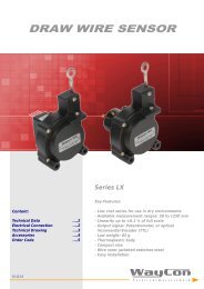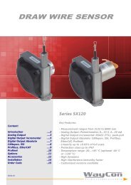
DRAW WIRE SENSOR SX80
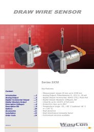
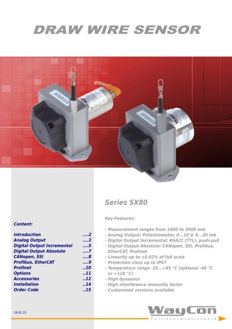
- Measurement ranges from 1000 to 3000 mm - Analog Output: Potentiometer, 0...10 V, 4...20 mA - Digital Output Incremental: RS422 (TTL), push-pull - Digital Output Absolute: CANopen, SSI, Profibus, EtherCAT, Profinet - Linearity up to ±0.02% of full scale - Protection class up to IP67 - Temperature range -20...+85 °C (optional -40 °C or +120 °C) - High dynamics - High interference immunity factor - Customised versions available
- Measurement ranges from 1000 to 3000 mm
- Analog Output: Potentiometer, 0...10 V, 4...20 mA
- Digital Output Incremental: RS422 (TTL), push-pull
- Digital Output Absolute: CANopen, SSI, Profibus,
EtherCAT, Profinet
- Linearity up to ±0.02% of full scale
- Protection class up to IP67
- Temperature range -20...+85 °C (optional -40 °C
or +120 °C)
- High dynamics
- High interference immunity factor
- Customised versions available

You also want an ePaper? Increase the reach of your titles
YUMPU automatically turns print PDFs into web optimized ePapers that Google loves.
<strong>DRAW</strong> <strong>WIRE</strong> <strong>SENSOR</strong><br />
Series <strong>SX80</strong><br />
Content:<br />
Introduction ....2<br />
Analog Output ....3<br />
Digital Output Incremental ....5<br />
Digital Output Absolute ....7<br />
CANopen, SSI ....8<br />
Profibus, EtherCAT ....9<br />
Profinet ..10<br />
Options ..11<br />
Accessories ..12<br />
Installation ..14<br />
Order Code ..15<br />
Key-Features:<br />
- Measurement ranges from 1000 to 3000 mm<br />
- Analog Output: Potentiometer, 0...10 V, 4...20 mA<br />
- Digital Output Incremental: RS422 (TTL), push-pull<br />
- Digital Output Absolute: CANopen, SSI, Profibus,<br />
EtherCAT, Profinet<br />
- Linearity up to ±0.02% of full scale<br />
- Protection class up to IP67<br />
- Temperature range -20...+85 °C (optional -40 °C<br />
or +120 °C)<br />
- High dynamics<br />
- High interference immunity factor<br />
- Customised versions available<br />
16.01.15
- 2 -<br />
INTRODUCTION<br />
WayCon Positionsmesstechnik GmbH is a manufacturer of high quality draw wire position sensors for<br />
industrial use. Due to its small overall size, its short assembly time and its possible customisation,<br />
the SX sensor technology is a cost-effective and flexible solution for a wide range of industrial<br />
applications. The dynamics of the draw wire transducer allows a high motion speed and acceleration<br />
of the measuring target. Its rugged design and high quality makes applications in harsh industrial<br />
environments possible. Special instruments are available with mounting service of encoder on site,<br />
as well as customised versions of housing.<br />
Sensor principle:<br />
The key component of a draw wire sensor is a highly flexible steel wire rope, that is winded singlelayered<br />
on an ultra light capstan. This capstan is connected to the sensor housing by a pre-stressed<br />
spring. The end of the steel wire rope, that is equipped with a rope clip gets connected to the target<br />
object. As soon as the distance between sensor and target object changes, the steel wire rope gets<br />
pulled out of the sensor and is rolled off the capstan (or vice versa). The shaft of the capstan is<br />
connected to a potentiometer (for analog output signals), or to an encoder (for digital output<br />
signals). If there is a rotation of the capstan due to a change in the distance to the target object, the<br />
sensor element will turn proportionally. This way the potentiometer, or the encoder converts a linear<br />
movement into a proportional electrical signal. If a standard analog output signal, like 0...10 V or<br />
4...20 mA is needed, the sensor is equipped with an additional electronics.<br />
rotating shaft<br />
sensor element:<br />
potentiometer<br />
measuring rope<br />
rope capstan<br />
example: SX50<br />
tension spring<br />
electronics:<br />
converts the potentiometer<br />
output into an analog output<br />
SPECIAL FEATURES<br />
easy rope fixation with rope clip<br />
ball bearing drill protection<br />
flexible and shielded sensor cable<br />
measuring rope<br />
(stainless steel)<br />
M12-connector system or<br />
cable output<br />
bushing<br />
anodised<br />
aluminium housing<br />
waterproof housing<br />
IP65 or IP67<br />
dynamic spring drive<br />
with PA6 case<br />
for high displacement speed<br />
2 ball bearings<br />
high linearity<br />
quick and easy mounting<br />
WARNING NOTICES<br />
• Don‘t let the rope snap back. If the rope is retracted freely, this may lead to injuries (whiplash effect) and the device may be damaged.<br />
Caution when unhooking and retracting the rope into the sensor.<br />
• Never exceed the specified measurement range when extracting the rope!<br />
• Do not try to open the device. The stored energy of the spring drive may lead to injuries when being mishandled.<br />
• Do not touch the rope when operating the sensor.<br />
• Avoid guiding the rope over edges or corners. Use a deflection pulley instead.<br />
• Do not operate the sensor if the rope is buckled or damaged. A ripping of the rope may lead to injuries or a damaging of the sensor.
- 3 -<br />
TECHNICAL DATA ANALOG OUTPUT<br />
Measurement range * [mm] 1000 1500 2000 2500 3000<br />
Linearity [%] 0.15 0.15 0.10 0.10 0.10<br />
Improved linearity (optional) [%] 0.10 0.10 0.05 0.05 0.05<br />
Resolution<br />
see types of output table below<br />
Sensor element<br />
Hybrid Potentiometer<br />
Connection<br />
Protection class<br />
connector output M12 axial or cable output axial 2 m (TPE cable)<br />
IP65, optional IP67<br />
Humidity<br />
maximum 90 % relative, no condensation<br />
Temperature<br />
[°C] standard: -20...+85 / optional: -40...+85 / optional: -20...+120 °C (only with Potentiometer (1R) and cable output (KA))<br />
Mechanical data extraction force, maximum velocity and maximum acceleration see table page 13<br />
Life expectancy<br />
approx. 2 million full strokes (dependent on the displacement speed)<br />
Weight [g] 300 to 500, depending on the measurement range<br />
Housing<br />
aluminium, titanium-grey anodised, spring case PA6<br />
Accessories cables, connectors, digital displays, deflection pulley, rope extensions, magnetic clamp (see pages 11 and 12)<br />
* other ranges on request<br />
TYPES OF ANALOG OUTPUT<br />
Output: Potentiometer (voltage divider)<br />
Output<br />
1 kΩ<br />
Supply<br />
max. 30 V<br />
Recommended cursor current<br />
< 1 µA<br />
Resolution<br />
theoretically unlimited, limited by the noise<br />
Noise<br />
dependent on the quality ot the power supply<br />
Working temperature -20...+85 °C , optional: -40...+85 °C / -20...+120 °C<br />
Temperature coefficient<br />
± 0.0025 %/K<br />
V+<br />
+ V+ V<br />
Cursor<br />
GND<br />
Output: Voltage 0...10 V<br />
Output<br />
0...10 V, galvanically isolated, 4 conductors<br />
Supply<br />
12...30 VDC<br />
Current consumption<br />
max. 22.5 mA (unloaded)<br />
Output current<br />
max. 10 mA, min. load 10 kOhm<br />
Dynamics < 3 ms from 0...100 % and 100...0 %<br />
Resolution<br />
limited by the noise<br />
Noise<br />
Inverse-polarity protection<br />
yes, infinite<br />
Short-circuit proof<br />
yes, permanent<br />
Working temperature -20...+85 °C , optional: -40...+85 °C<br />
Temperature coefficient<br />
0.0037 %/K<br />
Electromagnetic compatibility (EMC) according to EN 61326-1:2006<br />
V+<br />
+ V+ V<br />
Signal<br />
GND Sig.<br />
GND<br />
Note: GND Sig. and GND may be connected in<br />
a 3-wire system.<br />
3 mV ss typical, max. 37 mV ss<br />
A<br />
Output: Current 4...20 mA<br />
Output<br />
Supply<br />
4...20 mA, 2 conductors<br />
12...30 VDC<br />
Output current<br />
Dynamics<br />
max. 50 mA in case of error<br />
< 1 ms from 0...100 % and 100...0 %<br />
Resolution<br />
limited by the noise<br />
Noise<br />
Inverse-polarity protection<br />
0.03 mA ss = 6 mV ss an 200 Ohm<br />
yes, infinite<br />
Working temperature -20...+85 °C , optional: -40...+85 °C<br />
Temperature coefficient<br />
0.0079 %/K<br />
Electromagnetic compatibility (EMC) according to EN 61326-1:2006<br />
+<br />
V+<br />
V+<br />
Signal
- 4 -<br />
TECHNICAL <strong>DRAW</strong>ING ANALOG OUTPUT<br />
Detail drawing for measurement ranges 1500, 2500, 3000 mm<br />
connector output axial<br />
connector output radial<br />
Range Output B<br />
1000/ 2000 mm Potentiometer 73<br />
1000/ 2000 mm 10V / 420A 87<br />
1500 mm see detail drawing<br />
2500/ 3000 mm see detail drawing<br />
ELECTRICAL CONNECTION ANALOG OUTPUT<br />
Cable output<br />
Cable type<br />
TPE, flexible<br />
Cable direction<br />
axial<br />
Length<br />
standard: 2 m, (others on request)<br />
Diameter<br />
4.5 mm<br />
Wire<br />
0.25 mm²<br />
Temperature fixed installation -30...+85 °C<br />
flexible installation -20...+85 °C<br />
Cable colour 0...10 V 4...20 mA 1 kOhm<br />
brown V + V + V +<br />
white Signal n. c. Cursor<br />
blue GND Signal GND<br />
black GND Signal n. c. n. c.<br />
Connector output, M12, 4 poles<br />
Pin 0...10 V 4...20 mA 1 kOhm<br />
1 V + V + V +<br />
2 Signal n. c. Cursor<br />
3 GND Signal GND<br />
4 GND Signal n. c. n. c.
- 5 -<br />
TECHNICAL DATA DIGITAL OUTPUT INCREMENTAL<br />
Measurement range * [mm] 1000 / 1500 / 2000 / 2500 / 3000<br />
Linearity [%] 0.05, independent of the measurement range<br />
Improved linearity (optional) [%] 0.02, independent of the measurement range<br />
Selectable resolution<br />
[Pulses/mm] 0.5 / 1.25 / 2.5 / 5 / 10 / 25 (this resolution can be raised by the factor 4 using quadruple edge detection)<br />
Z-Pulse distance [mm] 200<br />
Sensor element<br />
Incremental-Encoder (with optical code disk)<br />
Output signal<br />
Connection<br />
Protection class<br />
A/B-Pulses (90° phase-delayed), Z-Pulse (plus inverted pulses A not , B not , Z not )<br />
M12 connector output or cable output with 2.0 m cable (PVC), open ends<br />
IP65, optional IP67<br />
Humidity<br />
maximum 90 % relative, no condensation<br />
Temperature range [°C] -20...+85<br />
Mechanical data extraction force, maximum velocity and maximum acceleration see table page 13<br />
Life expectancy<br />
approx. 2 million full strokes (dependent on the displacement speed)<br />
Weight [g] approx. 750<br />
Housing<br />
aluminium, titanium-grey anodised, spring case PA6<br />
Accessories digital displays, deflection pulley, rope extensions, magnetic clamp (see pages 12 and 13)<br />
* other ranges on request<br />
Electrical Data<br />
Linedriver L<br />
RS422 (TTL-compatible)<br />
Push-Pull G<br />
Power supply +V [VDC] 5, ±5 % 8...30<br />
Current consumption (no load)<br />
Load/ Channel<br />
Pulse frequency<br />
[mA]<br />
[mA]<br />
[kHz]<br />
typical 40, max. 90 typical 40, max. 100<br />
max. ±20 max. ±40<br />
max. 300 max. 200<br />
Signal level high [V] min. 2.5 min. +V – 3<br />
Signal level low<br />
[V]<br />
max. 0.5 max. 0.5<br />
Sensor<br />
Circuit<br />
Sensor<br />
Circuit<br />
Recommended circuit<br />
+5 V<br />
A<br />
Z<br />
+5 V<br />
A<br />
R L<br />
+V = 8..30 V<br />
0 V<br />
Ā<br />
0 V<br />
Ā<br />
0 V<br />
Z = 120 Ohm<br />
R L<br />
= 1 kOhm<br />
OUTPUT SIGNAL DIGITAL OUTPUT INCREMENTAL<br />
Output signal<br />
90° 360°<br />
Pulses A and B are 90° phase-delayed (detection of direction). The Z-<br />
Pulse is emitted once per turn. The Z-Pulse distance is 125 mm (=<br />
circumference of the rope drum) and can be used as a reference mark.<br />
A<br />
Th diagram shows the signal without inverted signals; time line for<br />
return of rope.<br />
B<br />
Z<br />
90°<br />
Z-Pulse with A/B<br />
AND-related<br />
rope retracting into sensor
- 6 -<br />
TECHNICAL <strong>DRAW</strong>ING DIGITAL OUTPUT INCREMENTAL<br />
Digital Output Incremental<br />
Range<br />
D<br />
1000/ 1500/ 2000 mm 21<br />
2500/ 3000 mm 35<br />
Output<br />
B<br />
cable/ connector axial, cable radial 54.3<br />
connector radial 64.3<br />
CONNECTION DIGITAL OUTPUT INCREMENTAL<br />
Signal 0 V +V 0 V sens<br />
* +V sens<br />
* A A Not B B Not Z Z Not screen<br />
Connector M23, 12-pole 10 12 11 2 5 6 8 1 3 4 housing<br />
Connector M12, 8-pole 1 2 - - 3 4 5 6 7 8 housing<br />
Cable output white brown black violet green yellow grey pink blue red housing<br />
* For Linedriver L only. For long cable lengths it may occur that the operating voltage at the sensor does not suffice due to the output resistance. With the sensor lines 0 V sens<br />
and +V sens<br />
the operating voltage can be checked and, if necessary, be readjusted at the input connection.<br />
+V: Encoder power supply +VDC A, A Not : Incremental output channel A<br />
0 V: Encoder power supply ground GND (0 V) B, B Not : Incremental output channel B<br />
0 V sens / +V sens : Using the sensor outputs of the encoder, the voltage Z, Z Not : Reference signal<br />
present can be measured and if necessary increased accordingly<br />
Connector output, M23, 12 poles<br />
Cable output<br />
Connector output, M12, 8 poles<br />
Cable type<br />
PVC, flexible<br />
Cable direction<br />
radial or axial<br />
Length<br />
Diameter<br />
Wires<br />
2.0 m<br />
ø 4.5 mm<br />
8 (push-pull) and 10 (linedriver) x 0.14 mm²<br />
Temperature fixed installation -30...+85 °C<br />
flexible installation -20...+85 °C<br />
Assignment<br />
see table above
- 7 -<br />
TECHNICAL DATA DIGITAL OUTPUT ABSOLUTE<br />
CANopen SSI Profibus-DP<br />
EtherCAT Profinet<br />
Measurement range [mm] 1000 / 1500 / 2000 / 2500 / 3000<br />
Linearity [%] 0.05, independent of the measurement range<br />
Resolution scalable (with Software) yes no yes yes yes<br />
Standard resolution [Pulses/mm] 40,96 20,48 40,96 40,96 40,96<br />
[Bit] 13 12 13 13 13<br />
Maximum resolution [Pulses/mm] 327.68 - 327.68 327.68 327.68<br />
[Bit] 16 - 16 16 16<br />
Sensor element<br />
Multiturn-Absolute-Encoder (with optical code disk)<br />
Connection cable gland radial 1 x connector M23 cable gland radial 3 x connector M12 3 x connector M12<br />
2 x radial, 12 poles 3 x 4 pole, radial 4 pole, radial<br />
Power supply [VDC] 10...30 (reverse polarity protection of the power supply)<br />
Current consumption (no load, 24 V) [mA]<br />
max. 100 max. 50 max. 120 max. 120 max. 200<br />
Protection class<br />
IP65, optional IP67<br />
Humidity<br />
Temperature [°C]<br />
max. 90 % relative, no condensation<br />
-20...+80<br />
Mechanical data extraction force, maximum velocity and maximum acceleration see table page 14<br />
Life expectancy<br />
approx. 2 million full strokes (dependent on the displacement speed)<br />
Weight [g] approx. 1100<br />
Housing<br />
aluminium, titanium-grey anodised, spring case PA6<br />
Special cables needed yes yes yes yes yes<br />
Accessories cable, connector, digital display,deflection pulley, rope extensions, magnetic clamp (see pages 12 and 13)<br />
Other encoder types are available on request<br />
TECHNICAL <strong>DRAW</strong>ING DIGITAL OUTPUT ABSOLUTE<br />
Note: for dimensions of the sensor housing please see page 4.<br />
CANopen: Bus terminal cover with terminal box<br />
SSI: M23 connector<br />
Profibus: Bus terminal cover (terminal box)<br />
EtherCAT, Profinet: 3 x M12 connector<br />
*<br />
* Profinet: 80
- 8 -<br />
DESCRIPTION CANopen<br />
Parameters of the CANopen Interface<br />
Code<br />
Interface<br />
Protocol<br />
Baud rate<br />
Node address<br />
Termination switchable<br />
SET Button (Option)<br />
LED<br />
Binary<br />
CAN High-Speed acc. to ISO 11898, Basic- and Full-CAN, CAN Specification 2.0 B<br />
CANopen profile DS406 V3.2 with manufacturer-specific add-ons<br />
10 ... 1000 kbit/s (can be set via DIP switches/ Software configurable)<br />
1...127 (can be set via rotary switches/ Software configurable)<br />
can be set via DIP switches/ Software configurable<br />
Zero or defined value option<br />
LED is ON with the following fault conditions: Sensor error (internal code or LED error) too low voltage, over-temperature<br />
Electrical connection CANopen<br />
Bus out<br />
Bus in<br />
Signal CAN_GND CAN_L CAN_H 0 V +V 0 V +V CAN_L CAN_H CAN_GND<br />
Abbreviation CG CL CH 0 V +V 0 V +V CL CH CG<br />
DESCRIPTION SSI<br />
Parameters of the SSI interface<br />
Output driver<br />
RS485 Transceiver-type<br />
Permissible load/channel<br />
max. ±20 mA<br />
Signal level<br />
HIGH: typ 3.8 V<br />
LOW: with I Load = 20 mA typ 1.3 V<br />
Resolution<br />
12 bit<br />
Code<br />
Gray<br />
SSI clock rate<br />
ST-resolution: 50 kHz...2 MHz<br />
Monoflop time ≤ 15 µs<br />
Data refresh rate<br />
≤ 1 µs<br />
Status and Parity bit<br />
on request<br />
SET Input (optional)<br />
The encoder can be set to zero at any position by means of a HIGH signal on<br />
the SET input. Other preset values can be factory-programmed. The SET input<br />
has a signal processing time of approx. 1 ms, after which the new position<br />
data can be read via SSI or BiSS-C. Once the SET function has been triggered,<br />
the encoder requires an internal processing time of typ. 200 ms; during this<br />
time the power supply must not be switched off.<br />
The SET function should be carried out whilst the encoder is at rest.<br />
SET Input<br />
Input<br />
Input type<br />
Signal level<br />
(+V = power supply)<br />
Input current<br />
Min. pulse duration (SET)<br />
Input delay<br />
New position data readable after<br />
Internal processing time<br />
active HIGH<br />
comparator<br />
HIGH: min 60% of +V, max. +V<br />
LOW: max. 25% of +V<br />
- 9 -<br />
DESCRIPTION PROFIBUS DP<br />
Parameters of the Profibus DP interface<br />
Code<br />
Interface<br />
Protocol<br />
Baud rate<br />
Device address<br />
Termination switchable<br />
SET Button (Option)<br />
LED<br />
Binary<br />
Profibus DP 2.0 Standard (DIN 19245 Part 3), RS485 Driver galvanically isolated<br />
Profibus Encoder Profile V1.1 Class1 and Class2 with manufacturer-specific add-ons<br />
maximum 12 Mbit/s<br />
1...127 (set by rotary switches)<br />
set by DIP switches<br />
Zero or defined value option<br />
LED is ON with the following fault conditions: Sensor error, Profibus error<br />
Electrical connection Profibus<br />
Bus IN<br />
Bus OUT<br />
Signal B A 0 V +V 0 V +V B A<br />
Terminal 1 2 3 4 5 6 7 8<br />
The shield of the connection cable must be connected over a large area via the cable gland.<br />
DESCRIPTION EtherCAT<br />
Parameters of the Ether CAT Interface<br />
Code<br />
Binary<br />
Protocol<br />
EtherNet / EtherCAT<br />
Modes<br />
Freerun, Distributed Clock<br />
Diagnostic LED red LED is ON with the following fault conditions: Sensor error (internal code or LED error), low voltage, over-temperature<br />
Run LED green LED is ON with the following conditions: Preop-, Safeop and Op-State (EtherCAT Status machine)<br />
2 x Link LEDs yellow LED is ON with the following conditions (Port IN and Port OUT): Link detected<br />
Electrical connection EtherCAT<br />
Signal Transmit data + Receive data + Transmit data - Receive data -<br />
Bus Port in Abbreviation TxD+ RxD+ TxD- RxD-<br />
PIN 1 2 3 4<br />
Power Signal Voltage + - Voltage - -<br />
Abbreviation +V - 0 V -<br />
supply<br />
PIN 1 2 3 4<br />
Signal Transmit data + Receive data + Transmit data - Receive data -<br />
Bus Port out Abbreviation TxD+ RxD+ TxD- RxD-<br />
PIN 1 2 3 4
- 10 -<br />
DESCRIPTION PROFINET<br />
Parameters of the Profinet interface<br />
Code<br />
Binary<br />
Protocol PROFINET 10<br />
LED Link1/Link2<br />
two coloured: green = active link<br />
yellow = data transfer<br />
Ezturn Software for Profinet (supplied with the encoder)<br />
- Monitoring of cyclic data (e.g. position, speed)<br />
- Monitoring of acyclic data (e.g. IMO, electronic name plate, encoder parameters,<br />
warnings and error messages, preset)<br />
- Setting of preset values<br />
- Firmware updates via the bus<br />
Electrical connection Profinet<br />
Signal Transmit data + Receive data + Transmit data - Receive data -<br />
Bus Port 1 Abbreviation TxD+ RxD+ TxD- RxD-<br />
PIN 1 2 3 4<br />
Power Signal Voltage + - Voltage - -<br />
Abbreviation +V - 0 V -<br />
supply<br />
PIN 1 2 3 4<br />
Signal Transmit data + Receive data + Transmit data - Receive data -<br />
Bus Port 2 Abbreviation TxD+ RxD+ TxD- RxD-<br />
PIN 1 2 3 4
- 11 -<br />
OPTIONS<br />
Option Order code Description<br />
Protection class IP67 (instead of IP65)<br />
Corrosion protection by HARTCOAT ®<br />
Best corrosion protection<br />
only in combination with analog output<br />
IP67<br />
CO(80)<br />
ICP(80)<br />
The regular ball bearings are replaced by stainless steel ball bearings.<br />
Note that with this option there may occur a light hysteresis in the output signal due to the special sealing<br />
The max. acceleration and displacement speed are reduced to 60 % of the specified value.<br />
Increased temperature range Low TEMP-40-SX-ST Spezial components and a low temperature grease make a working temperature down to -40 °C<br />
only in combination with analog output<br />
Increased temperature range High<br />
only in combination with potentiometer 1R<br />
TEMP120<br />
(up to +85°C) possible.<br />
(NOT in combination with analog or digital output signals)<br />
Changed rope outlet S1, S2, S3 S1: rope outlet sideways at the top<br />
S2*: rope outlet sideways at the bottom<br />
S3*: rope outlet on the bottom<br />
* with modified mounting plate<br />
see page 13<br />
Changed cable or K1, K2, K3 Standard: sideways, opposite to the rope outlet<br />
connector orientation<br />
only for digital incremental output<br />
and digital incremental output<br />
Use option IP67, if sensor will operate in a humid environment.<br />
All components of the housing and the inner mechanics get HARTCOAT ® coated.<br />
This coating is a hard-anodic oxidation that protects the sensor from corrosion by aggressive media<br />
(e. g. sea water) with a hard ceramics-like layer<br />
The regular ball bearings are replaced by stainless steel ball bearings.<br />
This option combines the options CO (HARTCOAT ® -coating) and IP67 (protection class IP67).<br />
In addition, a increased corrosive protection is achieved by the use of special components.<br />
Sensors with potentiometer output (1R) can be operated from -20 to +120 °C when this option is used.<br />
K1: at the top<br />
K2: sideways, same side as the rope outlet<br />
K3: at the bottom<br />
Rope outlet<br />
standard<br />
Cable/connector<br />
standard<br />
Ring eye RI20 The end of the wire rope is equipped with a ring eye<br />
instead of a rope clip.<br />
Inside diameter 20 mm<br />
Rope fixation by M4 thread M4 Optional, pivoted rope fixation with screw thread M4, length 22 mm.<br />
Ideal for attachment to through holes or thread holes M4.<br />
rope clip with drill<br />
protection<br />
(standard)<br />
Optional<br />
M4-fixation<br />
Inverted output signal<br />
only in combination with analog output<br />
IN<br />
The analog signal of the sensor is increasing by extracting the rope (standard).<br />
Option IN inverts the signal, i. e. the signal of the sensor declines by extracting the rope.<br />
output signal<br />
10V/20mA<br />
inverted<br />
0V/4mA standard<br />
range<br />
0 FS<br />
retract<br />
extract
- 12 -<br />
ACCESSORIES<br />
Deflection pulley - UR2<br />
The rope must be extracted from the sensor vertically. The maximum variation from the<br />
vertical is 3°. A deflection pulley allows a change in the direction of the wire rope. Several<br />
pulleys may be used. The rope clip must not be guided over the deflection pulley.<br />
material:<br />
anodised aluminium, POM<br />
mounting: by 2 hexagon socket or countersunk screws M6,<br />
vertical or horizontal mounting possible.<br />
Ball bearings: with special low temperature grease and RS-sealing.<br />
Temperature: -40...+80 °C.<br />
Rope extension - SV<br />
For bridging a greater distance between the measuring target and the sensor a rope extension<br />
can be applied. The rope clip must not be guided over the deflection pulley.<br />
Please specify the length needed in your order (XXXX). The minimum length is 150 mm:<br />
SV1-XXXX: rope extension (150...4995 mm)<br />
SV2-XXXX: rope extension (5000...19995 mm)<br />
SV3-XXXX: rope extension (20000...40000 mm)<br />
Magnetic clamp - MGG1<br />
Use the magnetic clamp to quickly attach the rope to metallic objects without any assembly time. A rubber coating<br />
provides gentle contact (e. g. on varnished surfaces) and prevents from slipping due to vibration.<br />
The magnet consists of a neodym core for an increased adhesive force of 260 N. The hook makes it easy to attach the<br />
rope clip.<br />
ACCESSORIES ANALOG Output<br />
Cable with connector M12, 4 poles, shielded<br />
K4P2M-S-M12<br />
K4P5M-S-M12<br />
K4P10M-S-M12<br />
K4P2M-SW-M12<br />
K4P5M-SW-M12<br />
K4P10M-SW-M12<br />
2 m, connector straight<br />
5 m, connector straight<br />
10 m, connector straight<br />
2 m, connector angular<br />
5 m, connector angular<br />
10 m, connector angular<br />
PIN No. cable colour PIN No. cable colour<br />
Pin 1 brown Pin 3 blue<br />
Pin 2 white Pin 4 black<br />
Mating Connector M12, 4 poles, shielded<br />
D4-G-M12-S straight, M12 for self assembly<br />
D4-W-M12-S angular, M12 for self assembly<br />
protection class: IP67<br />
temperature: -25...+90 °C<br />
cable passage: ø 4...8 mm<br />
wire cross-section: 0.14...0.34 mm²<br />
mode of connection: spring cage<br />
Digital display - PAXD ( for Potentiometer)<br />
Use the PAXD display to visualise the measured distance of the position transducer with a potentiometer as sensor<br />
element. A transmission of the measurement data to a computer or PLC can be done with interface plug-in cards.<br />
Inputs: Potentiometer signal<br />
Analog output (plug-in cards): 0...20 mA, 4...20 mA, 0...10 V<br />
Serial interfaces (plug-in cards): RS485, RS232, DeviceNet, USB, Profibus, Relay output, Transistor output<br />
Protection class: IP65 (Front panel)<br />
Display: 5 digits<br />
PAXD000B: 1 channel, power supply: 85 to 250 VAC<br />
PAXD001B: 1 channel, power supply:: 11 to 36 VDC/24 VAC<br />
For further information please see the data sheet of the PAXD display series
- 13 -<br />
ACCESSORIES ANALOG OUTPUT<br />
Digital displays PAXP (1 channel) and PAXDP (2 channels) for sensors with analog output signals 0..10V or 4..20 mA<br />
Use the PAXD or PAXDP display to visualise the measured distance of transducers with an analog output signal.<br />
A transmission of the measurement data to a computer or PLC can be done with interface plug-in cards.<br />
Inputs: 0...10 V or 4...20 mA, 2 independent counters (for PAXDP)<br />
Analog output (plug-in cards): 0...20 mA, 4...20 mA, 0...10 V<br />
Serial interfaces (plug-in cards):<br />
Protection class: IP65 (front panel)<br />
Display: 5 digits<br />
RS485, RS232, DeviceNet, USB, Profibus, Relay output, Transistor output<br />
PAXP000B: 1 channel, power supply: 85 to 250 VAC<br />
PAXP001B: 1 channel, power supply: 11 to 36 VDC/24 VAC<br />
PAXDP000B: 2 channels, power supply: 85 to 250 VAC<br />
PAXDP001B: 2 channels, power supply: 11 to 36 VDC/24 VACC<br />
For further information please see the PAXD and PAXDP data sheet.<br />
ACCESSORIES DIGITAL OUTPUT INCREMENTAL<br />
Cable with connector M12, 8 poles, shielded Mating connector M12, 8 poles, shielded Mating connector M23, 12 poles<br />
K8P2M-S-M12 2 m, connector straight D8-G-M12-S mating connector straight CON012-S straight, metal housing<br />
K8P5M-S-M12 5 m, connector straight D8-W-M12-S mating connector angular wire diameter: AWG 16...26 mm²<br />
K8P10M-S-M12 10 m, connector straight protection class: IP67<br />
cable diameter: ø 5.5...10 mm<br />
K8P2M-SW-M12 2 m, connector angular<br />
temperature: -25...+90 °C<br />
K8P5M-SW-M12 5 m, connector angular cable passage: ø 4...8 mm<br />
K8P10M-SW-M12 10 m, connector angular<br />
wire diameter: 0.14...0.34 mm²<br />
CON012-S<br />
Digital distance and speed display - WAY-D for incremental output signals<br />
Use the WAY-D display to visualise the measured distance or the speed (tachometer) of the position transducer.<br />
A transfer of data to a PC or PLC can be done with the RS232 interface of the WAY-DR.<br />
Protection class:<br />
IP65 (front panel)<br />
Display: 6 digits<br />
Supply:<br />
115 / 250 VAC<br />
Output Linedriver L (TTL, RS422):<br />
WAY-DS-5VH:<br />
WAY-DG-5VH:<br />
WAY-DR-5VH:<br />
display only, input level TTL<br />
display with two presets and switching outputs, input level TTL<br />
display with serial interface RS232 / RS485, input level TTL<br />
Output Push-Pull G:<br />
WAY-DS:<br />
WAY-DG:<br />
WAY-DR:<br />
display only, input level HTL<br />
display with two presets and switching outputs, input level HTL<br />
display with serial interface RS232 / RS485, input level HTL<br />
For further information please see the WAY-D data sheet.<br />
ACCESSORIES DIGITAL OUTPUT ABSOLUTE SSI<br />
Digital distance and speed display - WAY-SSI for SSI output signals<br />
Use the WAY-SSI display to visualise the measured distance or the speed (tachometer) of the position transducer.<br />
A transfer of data to a PC or PLC can be done with the RS232 interface of the WAY-SSI-R.<br />
Protection class:<br />
IP65 (front panel)<br />
Display: 6 digits<br />
Supply:<br />
115 / 250 VAC<br />
WAY-SSI-S: display only<br />
WAY-SSI-A: display with analog output<br />
WAY-SSI-G: display with two presets and switching outputs<br />
WAY-SSI-R: display with serial interface RS232 / RS485<br />
For further information please see the WAY-SSI data sheet.
- 14 -<br />
MECHANICAL DATA<br />
Measurement Range Extraction Force Speed* Acceleration*<br />
[mm]<br />
F min<br />
[N] F max<br />
[N] V max<br />
[m/s] a max<br />
[m/s²]<br />
1000 4.2 5.4 10 140<br />
1500 4.2 5.4 10 140<br />
2000 5.0 6.4 10 140<br />
2500 5.0 6.4 10 140<br />
3000 5.0 6.4 10 140<br />
* reduced to 60 % when option IP67 is used<br />
INSTALLATION<br />
• Mount the sensor at the designated place by using the fixing holes before extracting the rope and before attaching the rope to the<br />
measuring target.<br />
• Open the rope clip after the sensor is fully mounted and extract the measuring rope. Hook the rope clip on the measuring object<br />
and close the bracket of the clip. For safety reasons put a screw driver trough the clip to extract the rope.<br />
• Check the track of the measuring target on collision with the sensor housing and on exceeding the specified measurement range. When installing the sensor make<br />
sure that the rubber stopper does not touch the rope outlet.<br />
• Connect the electronics according to the sensor type. When laying the cables be careful not to under-run the minimal allowed bending radius of the cable (5 x<br />
cable diameter).<br />
• The rope must be extracted from the sensor vertically. The maximum variation from the vertical is 3°. Avoid carefully extracting the rope at an inclination, since<br />
the durability of the instrument would shorten considerably. If it is not possible to keep the limit of 3°, a deflection pulley has to be used.<br />
• The measuring range begins after approximately 2 mm extracted rope (=zero point). The mechanical reserve at the end of the measuring range is about 20 mm.<br />
• When mounting outdoors protect the sensor and the rope from icing at temperatures below 0 °C.<br />
• Guide the rope preferably in corners or guarded in channels to prevent pollution or accidental touch.<br />
• When operating the sensor, take care not to let the rope snap back by mistake or extract the rope over the specified measurement range, as this might<br />
destroy the sensor.<br />
• Maintenance: These instruments are maintenance-free. If however, the rope is soiled due to adverse environmental conditions, it can be cleaned with a cloth<br />
drenched in resin-free machine oil.<br />
Mounting: standard rope outlet, rope outlet sideways top (S1)<br />
The sensor is usually installed by using the regular mounting plate (see<br />
technical drawing on page 4).<br />
By disassembling the mounting plate, there are 4 threads (2 x M3, 2 x M5)<br />
in the sensor housing for alternative installation.<br />
Mounting: rope outlet sideways bottom (S2), rope outlet bottom (S3)<br />
Sensors with option rope outlet S2 and S3 have a modified base plate.
- 15 -<br />
ORDER CODE ANALOG OUTPUT<br />
<strong>SX80</strong><br />
Measurement Range [mm]<br />
1000 / 1500 / 2000 / 2500 / 3000<br />
Selectable Options<br />
Analog Output<br />
Potentiometer<br />
Voltage output<br />
Current output<br />
Connection<br />
1 kOhm<br />
0...10 V<br />
4...20 mA<br />
Connector output M12 axial<br />
Connector output M12 radial<br />
Cable output axial<br />
* for measurement ranges 1500, 2500, 3000 mm only<br />
Version<br />
1R<br />
10V<br />
420A<br />
SA<br />
SR*<br />
KA<br />
M4<br />
RI20<br />
S1<br />
S2<br />
S3<br />
IN<br />
L05<br />
L10<br />
SSB8<br />
TEMP-40-SX-ST<br />
TEMP120*<br />
IP67<br />
CO(80)<br />
ICP(80)<br />
rope fixation be M4 thread<br />
ring eye (instead of rope clip)<br />
rope outlet sideways top<br />
rope outlet sideways bottom<br />
rope outlet bottom<br />
inverted output signal<br />
improved linearity 0.05 %<br />
improved linearity 0.10 %<br />
stainless steel bearings<br />
increased temperature range low -40...+85°C<br />
increased temperature range high -20...+120 °C<br />
protection class IP67<br />
HARTCOAT coating <strong>SX80</strong><br />
increased corrosion protection <strong>SX80</strong><br />
Standard<br />
Sensor with options<br />
-<br />
O<br />
* only for 1R in combination with KA<br />
ORDER CODE DIGITAL OUTPUT INCREMENTAL<br />
<strong>SX80</strong><br />
Measurement Range [mm]<br />
Version<br />
1000 / 1500 / 2000 / 2500 / 3000<br />
-<br />
O<br />
Standard<br />
Sensor with options<br />
Resolution [Pulses/mm]<br />
0.5 / 1.25 / 2.5 / 5 / 10 / 25<br />
Selectable Options<br />
Output type<br />
Linedriver according to RS422 (TTL)<br />
Push-Pull<br />
Connection<br />
Connector output M23 radial<br />
Connector output M23 axial<br />
Connector output M12 radial<br />
Connector output M12 axial<br />
Cable output radial (2.0 m length)<br />
Cable output axial (2.0 m length)<br />
L<br />
G<br />
SR<br />
SA<br />
SRM<br />
SAM<br />
KR *<br />
KA *<br />
M4<br />
RI20<br />
S1<br />
S2<br />
S3<br />
K1<br />
K2<br />
K3<br />
L02<br />
IP67<br />
CO(80)<br />
rope fixation M4 thread<br />
ring eye (instead of rope clip)<br />
rope outlet sideways top<br />
rope outlet sideways bottom<br />
rope outlet bottom<br />
cable/connector orientation top<br />
cable/connector orientation left<br />
cable/connector orientation bottom<br />
improved linearity 0.02 %<br />
protection class IP67<br />
HARTCOAT coating <strong>SX80</strong><br />
* for linedriver: 10 wires (with additional sensor lines)<br />
for push-pull: 8 wires (without sensor lines)
- 16 -<br />
ORDER CODE DIGITAL OUTPUT ABSOLUTE<br />
<strong>SX80</strong><br />
Measurement Range [mm]<br />
1000 / 1500 / 2000 / 2500 / 3000<br />
Interfaces / Bus systems<br />
SSI<br />
CANopen<br />
Profibus DP<br />
EtherCAT<br />
Profinet<br />
Version<br />
Standard<br />
Sensor with options<br />
SSI<br />
CAN<br />
PRO<br />
CAT<br />
NET<br />
-<br />
O<br />
M4<br />
RI20<br />
S1<br />
S2<br />
S3<br />
K1<br />
K2<br />
K3<br />
IP67<br />
CO(80)<br />
Selectable Options<br />
rope fixation M4 thread<br />
ring eye (instead of rope clip)<br />
rope outlet sideways top<br />
rope outlet sideways bottom<br />
rope outlet bottom<br />
cable/connector orientation top<br />
cable/connector orientation left<br />
cable/connector orientation bottom<br />
protection class IP67<br />
HARTCOAT coating <strong>SX80</strong><br />
GENERAL ACCESSORIES<br />
UR2 Deflection pulley SV1-XXXX rope extension (150...4995 mm)<br />
MGG1 Magnetic clamp SV2-XXXX rope extension (5000...19995 mm)<br />
SV3-XXXX rope extension (20000...40000 mm)<br />
ACCESSORIES ANALOG OUTPUT<br />
Cable with mating connector M12, 4 poles, shielded<br />
Digital display 1 channel, 0...10V/4...20 mA<br />
K4P2M-S-M12 2 m, straight connector<br />
PAXP000B 1 channel, supply: 85 to 250 VAC<br />
K4P5M-S-M12 5 m, straight connector<br />
PAXP001B 1 channel, supply: 11...36 VDC/24 VAC<br />
K4P10M-S-M12 10 m, straight connector<br />
K4P2M-SW-M12 2 m, angular connector Digital display 2 channels, 0...10V/4...20 mA<br />
K4P5M-SW-M12 5 m, angular connector<br />
PAXDP00B 2 channels, supply: 85 to 250 VAC<br />
K4P10M-SW-M12 10 m, angular connector<br />
PAXDP01B 2 channels, supply: 11...36 VDC/24 VAC<br />
Mating Connector M12, 4 poles, shielded<br />
Digital display 1 channel, Potentiometer<br />
D4-G-M12-S straight, M12 for self assembly<br />
PAXD000B 1 channel, supply: 85 to 250 VAC<br />
D4-W-M12-S angular, M12 for self assembly<br />
PAXD001B 1 channel, supply: 11...36 VDC/24 VAC<br />
Additional cable for cable output KA (2 m length is standard)<br />
Kabel-TPE<br />
order code for 1 m of additional TPE cable
- 17 -<br />
ACCESSORIES DIGITAL OUTPUT INCREMENTAL<br />
Cable with mating connector M12, 8 poles, shielded<br />
Mating Connector M12, 8 poles, shielded<br />
K8P2M-S-M12 2 m, straight connector D8-G-M12-S straight, M12 for self assembly<br />
K8P5M-S-M12 5 m, straight connector D8-W-M12-S angular, M12 for self assembly<br />
K8P10M-S-M12 10 m, straight connector<br />
K8P2M-SW-M12 2 m, angular connector Digital display 1 channel, Linedriver L (input level TTL, RS422)<br />
K8P5M-SW-M12 5 m, angular connector<br />
WAY-DS-5VH display only<br />
K8P10M-SW-M12 10 m, angular connector WAY-DG-5VH display with two presets and switching outputs<br />
WAY-DR-5VH display with serial interface RS232 / RS485<br />
Cable with mating connector M23, 8 poles, shielded<br />
K8P2M-S-M23<br />
K8P5M-S-M23<br />
2 m, straight connector<br />
5 m, straight connector<br />
Digital display 1 channel, Push-Pull G<br />
K8P10M-S-M23 10 m, straight connector<br />
WAY-DS display only<br />
WAY-DG display with two presets and switching outputs<br />
Mating Connector M23, 12 poles, shielded WAY-DR display with serial interface RS232 / RS485<br />
CON012-S<br />
straight, M23 for self assembly, metal housing<br />
ACCESSORIES DIGITAL OUTPUT ABSOLUTE<br />
SSI output:<br />
CANopen output:<br />
K12P02M-S-M23-SSI 2 m cable, shielded, M23 connector straight K5P2M-B-M12-CAN 2 m cable, plug female M12, 5 poles, open ends<br />
K12P05M-S-M23-SSI 5 m cable, shielded, M23 connector straight K5P2M-SB-M12-CAN 2 m cable, connector male M12, 5 poles, plug female M12<br />
K12P10M-S-M23-SSI 10 m cable, shielded, M23 connector straight K5P2M-S-M12-CAN 2 m cable, connector male, M12, 5 poles, open ends<br />
K12P15M-S-M23-SSI<br />
CON012-S<br />
15 m cable, shielded, M23 connector straight<br />
Mating connector M23 shielded, straight, 12 poles<br />
Digital display 1 channel, for sensors with SSI signal<br />
EtherCAT / Profinet:<br />
WAY-SSI-S display only K4P2M-S-M12-CAT 2 m cable, connector male M12, 4 poles, open ends<br />
WAY-SSI-A<br />
display with analog output<br />
K4P5M-S-M12-CAT 5 m cable, connector male M12, 4 poles, open ends<br />
WAY-SSI-G<br />
display with two presets and switching outputs<br />
K4P10M-S-M12-CAT 10 m cable, connector male M12, 4 poles, open ends<br />
WAY-SSI-R display with serial interface RS232 / RS485 K4P2M-B-M12-CAT<br />
K4P5M-B-M12-CAT<br />
2 m cable, plug female M12, 4 poles, open ends<br />
5 m cable, plug female M12, 4 poles, open ends<br />
Profibus DP:<br />
K4P10M-B-M12-CAT 10 m cable, plug female M12, 4 poles, open ends<br />
K5P2M-B-M12-PROF<br />
K5P2M-SB-M12-PROF<br />
K5P2M-S-M12-PROF<br />
M12-PROF-AW<br />
2 m cable, plug female M12, 5 poles, open ends<br />
2 m cable, connector male M12, 5 poles, plug female M12<br />
2 m cable, connector male, M12, 5 poles, open ends<br />
terminator<br />
Subject to change without prior notice.<br />
WayCon Positionsmesstechnik GmbH<br />
email: info@waycon.de<br />
internet: www.waycon.de<br />
Head Office<br />
Mehlbeerenstr. 4<br />
82024 Taufkirchen<br />
Tel. +49 (0)89 67 97 13-0<br />
Fax +49 (0)89 67 97 13-250<br />
Office Köln<br />
Auf der Pehle 1<br />
50321 Brühl<br />
Tel. +49 (0)2232 56 79 44<br />
Fax +49 (0)2232 56 79 45