
Create successful ePaper yourself
Turn your PDF publications into a flip-book with our unique Google optimized e-Paper software.
Furuno's high-grade satellite compass<br />
provides superior heading accuracy for<br />
AIS, ECDIS, Radar and more<br />
Compass Rose<br />
Mode<br />
■ Provides highly accurate heading data<br />
for autopilot, radar, AIS, Sonar and<br />
plotting systems<br />
■ IMO MSC.116(73) type approved as a<br />
verified THD (Transmitting Heading<br />
Device) with high accurate 0.3° RMS<br />
■ Rapid 45°/s follow-up rate greatly<br />
exceeds IMO High Speed Craft<br />
requirements 20°/s<br />
■ High accurate GPS, WAAS Data –<br />
SOG, COG, ROT, and L/L<br />
■ High Contrast 4.5" Silver Bright LCD<br />
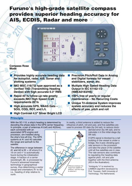
Principle<br />
With the SC-110, a ship's heading is determined by<br />
decoding the phase data in the GPS carrier frequency.<br />
In principle, a pair of antennas A1(ref) and A2(fore),<br />
each connected with an<br />
associated GPS engine and<br />
North<br />
processor, are installed along<br />
the ship's fore-aft line. The GPS<br />
systems at A1 and A2 calculate<br />
the range and azimuth to the<br />
Heading<br />
satellite.<br />
Antenna A3<br />
The difference in range between<br />
A1 and A2 is + n where is<br />
19 cm and n* is automatically<br />
found during the initialization<br />
stage. A fraction of a carrier<br />
n<br />
wavelength, , is processed by<br />
Furuno's advanced kinematic<br />
technology in geographical<br />
survey, thus determining a vector<br />
(range and orientation) A1 to A2,<br />
i.e., heading of ship relative to<br />
north.<br />
Antenna A1<br />
Vector to decide heading<br />
■ Precision Pitch/Roll Data in Analog<br />
and Digital formats for vessel<br />
stabilizers, sonar, etc.<br />
■ Multiple High Speed Heading Data<br />
Output in IEC 61162-1/2<br />
(NMEA0183/HS)<br />
■ 100% free of yearly or regular<br />
maintenance – No Recurring Costs<br />
■ Unique Tri-Antenna System improves<br />
system accuracy and reduces the<br />
effects of yaw, pitch and roll<br />
In reality, a third antenna is added to reduce the<br />
influence of pitch, roll and yaw, and five satellites are<br />
used to process 3D data (by 3rd sat), to reduce clockderived<br />
error (by 4th sat), and to<br />
calculate n in the initial stage (by<br />
5th sat).<br />
If GPS signal is blocked by a tall<br />
building or the vessel is under a<br />
bridge, the 3-axis vibrating-gyro<br />
rate sensors in the processor<br />
unit take the place of the satellite<br />
until all five satellites are in view.<br />
The rate sensors also contribute<br />
to regulating the heading data<br />
Antenna A2 against pitch, roll and yaw<br />
together with the third antenna<br />
(A3 in the illustration).<br />
Fore-aft line<br />
Difference between the<br />
range from satellite to<br />
antenna 1 and the range<br />
to antenna 2.<br />
*Ambiguity "n" is resolved by<br />
LAMBDA algorithm developed by<br />
Prof. Teussen, Delft University of<br />
Technology, The Netherlands.