

reprap-granule-extruder-tudelft1
reprap-granule-extruder-tudelft1
reprap-granule-extruder-tudelft1

Create successful ePaper yourself
Turn your PDF publications into a flip-book with our unique Google optimized e-Paper software.
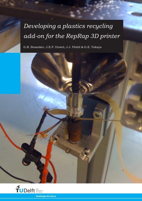
Developing a plastics recycling<br />
add-on for the RepRap 3D printer<br />
G.B. Braanker, J.E.P. Duwel, J.J. Flohil & G.E. Tokaya
Abstract<br />
The main theme of this paper is using domestic waste plastic to create new plastic products. A brief research is<br />
conducted in the <strong>granule</strong>-making field. This research functions as the foundation in selecting the right domestic<br />
appliance for creating <strong>granule</strong> of the right size for a small <strong>extruder</strong>. This had to be done in a way that regular<br />
people must be able to copy this process, so this should be as easy as possible.<br />
Parallel to this a literature review was conducted to find the right <strong>extruder</strong> principle for the creation of a<br />
mini <strong>extruder</strong>. A principle was selected and with the help of experts in the field of 3D printing and extruding this<br />
principle was evolved to a design. After lots of trial and error this design has been transformed into a working<br />
prototype.<br />
With this prototype five tests were conducted. These tests proved to be very valuable in obtaining new<br />
insight in problems that still have to be overcome. The most important problems that were faced are getting the<br />
right accuracy in the tolerances, heat development in the <strong>granule</strong> making process and creating a good <strong>granule</strong><br />
feed flow for the <strong>extruder</strong>. While trying to solve these problems other point of interest came along. This research<br />
can be seen as the starting point of the development of a new kind of domestic <strong>extruder</strong>.<br />
Keywords,<br />
Extrusion, <strong>granule</strong> <strong>extruder</strong>, mini extrusion, RepRap, 3d printing, domestic, plastics, recycling<br />
2 | Prototyping Lab (IO3028) - RepRap Recycle Add-on
Table of Contents<br />
1. Introduction 5<br />
2. The RepRap project 6<br />
3. From product to <strong>granule</strong> 8<br />
4. From <strong>granule</strong> to extrusion 14<br />
5. Adapting the prototype to the RepRap 23<br />
6. Conclusions and discussion 25<br />
7. Recommendations for further development 27<br />
8. References 29<br />
Appendixes:<br />
A. Blender <strong>granule</strong> tests<br />
B. Technical drawings of the parts used in the setup<br />
C. Extrusion screw manufacturing<br />
3 | Prototyping Lab (IO3028) - RepRap Recycle Add-on
4 | Prototyping Lab (IO3028) - RepRap Recycle Add-on
1<br />
İntroduction<br />
The RepRap is a 3D printer that is available for<br />
Western households. The technology behind the<br />
RepRap is open source and thus available online for<br />
free. All the printer’s plastic parts can be printed by<br />
the printer itself.<br />
The idea behind the RepRap is that it can<br />
produce products based on digital files one can<br />
download from the Internet or on CAD models which<br />
can be created by the owner of the RepRap. This way<br />
of producing articles will reduce transportation cost<br />
and the 3D printing process is efficient in material<br />
use. The big drawback, however, is that when people<br />
start to design products themselves with CAD<br />
software, the chance of misprinting objects increases.<br />
Misprints will result in waste. Next to this, lots of<br />
homes produce a giant amount of plastic waste. It<br />
would be very interesting to use these two waste<br />
flows to create new products.<br />
Therefore the purpose of this research is to<br />
explore the possibility to use domestic waste plastic<br />
as input for the RepRap. This exploration will be<br />
extended by an experiment involving two steps. The<br />
first step is creating <strong>granule</strong> sized material from a<br />
commercial product that can be used as input<br />
material. The second step is using <strong>granule</strong> to create<br />
an extrusion flow. The result of this research is an<br />
idea of the feasibility of this concept and a conceptual<br />
printer head design. The next step is fitting the<br />
prototype to the RepRap. The final printer head<br />
should only consist of parts that are either printable<br />
or easy accessible for normal consumers, to fit the<br />
RepRap philosophy.<br />
This research is carried out for the Bachelor elective<br />
course ‘Prototyping Lab’ at the faculty of Industrial<br />
Design Engineering of Delft University of Technology.<br />
In 10 weeks, the project was executed by a team of 4<br />
students working half-time on it.<br />
Since all team member were new in the world of<br />
rapid prototyping and the RepRap, first a literature<br />
review was carried out to determine interesting fields<br />
for a research, of which the <strong>granule</strong> <strong>extruder</strong> was<br />
chosen. In chapter 2 of this report, the findings of our<br />
review about the RepRap can be found. In chapter 3<br />
the process of converting a plactic object to <strong>granule</strong><br />
can be found. The process of changing this <strong>granule</strong><br />
into an extrusion, actions and tests carried out for<br />
developing the <strong>extruder</strong> can be found in chapter 4. A<br />
vision on how the results of this project can be<br />
adapted to an <strong>extruder</strong> that can be placed on the<br />
RepRap are found in chapter 5, while conclusions and<br />
recommendations of the project can be found in<br />
chapter 6 and 7, respectively.<br />
Our special thanks go out to Adrie Kooijman for his<br />
supervision, Jouke Verlinden for coordinating the<br />
course, Martin Verwaal for helping us with the test<br />
setup, Rolf Koster for his advice on the properties of<br />
plastics and extrusion characteristics and Kevin<br />
Kamman from the TU Delft PMB for helping us with<br />
machining the different parts.<br />
5 | Prototyping Lab (IO3028) - RepRap Recycle Add-on
2<br />
Ṫhe RepRap project<br />
In the beginning of this project, a literature review<br />
was carried out. The goal of this review was to gain<br />
some insight in the RepRap project and to determine<br />
a goal for the project. After the review, the subject of<br />
creating a recycling add-on for the printer was<br />
determined. An extract of the review, with a focus on<br />
the parts about the RepRap project, can be found in<br />
this chapter.<br />
The RepRap 3D printer project is, according to their<br />
creators, “a project to save the world… or at least to<br />
improve it”. The project is initiated by Adrian Bowyer,<br />
member of the Department of Mechanical Engineering<br />
at the University of Bath, United Kingdom 1 . The first<br />
RepRap machine was the Darwin, completed in<br />
October 2008 2 , see figure 2.1. Recently a new<br />
version, the Mendel, was released, having various<br />
improvements like a bigger print area, simpler<br />
assembly and a higher efficiency 3 .<br />
At Delft University of Technology, a Darwin<br />
printer created from a Bits from Bytes kit, is<br />
assembled by a previous project group. Bits from<br />
Bytes is an online reseller, selling complete RepRap<br />
kits made from plexiglass 4 . The available printer is a<br />
RepMan version 3.1.<br />
Building a complete printer costs about $400<br />
when producing all the parts at home, while<br />
commercial kits are available starting from $1200.<br />
2.1<br />
RepRap philosophy<br />
No current engineering manufacturing process is<br />
capable of exponentially expanding production,<br />
because none use self-replication. John von Neumann<br />
was the first person to propose self-replicating<br />
machines back in the 1960s 5 .<br />
The RepRap is built on the idea that anyone<br />
could manufacture products, anywhere in the world.<br />
It is an open-source project, with the goal to enable<br />
relatively low-cost 3d printing. This is realized by<br />
engineering a printer, using mostly simple standard<br />
components and of course the fact that both soft- and<br />
hardware are open-source. The hardware blueprints<br />
are available for free, so parts for the pinter can be<br />
produced at home. This leads to the next<br />
characteristic of the RepRap. Its name stands for<br />
REPlicating RAPid-prototyper: this means that the<br />
machine should be able to print the parts for a new<br />
printer. At this moment the RepRap can fabricate up<br />
to 50% of its own components 2 . To create the first<br />
RepRap of a family one can use a so called RepStrap 6 .<br />
Figure 2.1 - The Darwin RepRap<br />
The RepStrap project has been set-up to help<br />
people build there own RepRap machine without<br />
using an already existing RepRap machine. The goal<br />
of RepStrap is that anyone (no matter what<br />
education) can build his own complete RepRap only<br />
using tool and materials commonly available. Once<br />
someone has built his own RepRap machine, the<br />
printer is able to replicate itself and produce other<br />
useful parts. In this philosophy, the number of<br />
RepRap printer should be able to grow exponentially.<br />
2.2<br />
Working principle<br />
The machine is composed of a frame, built out of<br />
standard thread rods and printed parts. A platform,<br />
where the parts are meant to be built on, can move in<br />
the frame along the vertical axis. A stepper motor<br />
drives this platform up and down by using movement<br />
threads. On top of the frame rests the print head,<br />
which extrudes a thin layer of molten plastic to form a<br />
layer on the base platform. The <strong>extruder</strong> is moved<br />
along the horizontal axes by two stepper motors and<br />
toothed belts.<br />
6 | Prototyping Lab (IO3028) - RepRap Recycle Add-on
2 | The RepRap project<br />
Fused deposition modeling<br />
The object that is printed is built up layer by layer,<br />
with the platform moving down as each layer is<br />
finished 7 . This form of rapid prototyping is also known<br />
as fused deposition modelling. From studies, factors<br />
that influence the strength of a sample part, created<br />
with fused deposition modelling, appeared. Layer<br />
thickness, sample orientation, raster angle raster<br />
width and the air gap were of significant influence 8 .<br />
Assembly<br />
To collect all the parts necessary for building a<br />
RepRap, the Bill of Materials (BOM) can be accessed<br />
through the project’s official website. The BOM<br />
divides the RepRap into different subassemblies,<br />
based on function. The main frame with the XYZ<br />
movement is called the Cartesian Robot; other<br />
subassemblies are the Thermoplastic Extruder and<br />
different drivers and controllers for the RepRap and<br />
its motors. For all parts that cannot be build by a<br />
RepRap, detailed specifications and professional<br />
suppliers are listed. With the stepper motor, for<br />
example, two online suppliers are provided. For all<br />
the other parts, parts that a RepRap can print itself,<br />
both online suppliers and digital files are provided.<br />
Although there is a ‘standard’ version of the<br />
RepRap Darwin, the open source approach of the<br />
project initiated the possibility of creating add-ons to<br />
the printer, what is also the goal of this research<br />
project. This has resulted in the release of an<br />
alternative tool head, as a replacement of the<br />
thermoplastic <strong>extruder</strong> head. This ‘Paste <strong>extruder</strong>’<br />
can not extrude plastics, but all sorts of paste, from<br />
icing sugar to filler, and is still under development.<br />
Also, lots of other ideas for tool heads exist: from<br />
milling heads to a soldering tool 9 .<br />
Because of the number of subassemblies and<br />
the wish to be able to improve subassemblies without<br />
affecting the rest of the machine, the initiators of the<br />
RepRap project chose a modular approach. This<br />
means every component or assembly that is operated<br />
by electronics works complete separate of other<br />
components. The main controller is an Arduino, an<br />
open source microcontroller that is easy<br />
programmable 10 .<br />
One big disadvantage of the RepRap is that it<br />
needs to be assembled by people with technical<br />
knowledge. Since the whole philosophy of the project<br />
is to create a self-replicating device, current assembly<br />
is too hard for ‘normal’ people in their domestic<br />
environment. Further research is needed to get closer<br />
to that goal.<br />
CAD approach<br />
The digital files for the parts that are available on the<br />
RepRap website are so called STL (Stereo<br />
lithography) files, a widely used format for computeraided<br />
manufacturing 11 , although stereo lithography is<br />
not the technology used by RepRap. Many widely<br />
used CAD applications support importing and<br />
exporting STL, including AutoCAD, ProE, Rhino and<br />
Solid Works 12 . STL files only describe the surface<br />
geometry of a model, not colour, texture or any other<br />
attributes.<br />
The application that RepRap supports as CAD<br />
tool for part design is a programme called Art of<br />
Illusion (AoI). This programme is open-source and<br />
available for free. Although it is not created as a CAD<br />
programme more for assisting in animation, it was<br />
chosen because of its minimalistic and intuitive<br />
interface 13 .<br />
When sending a file to the RepRap trough USB<br />
and the serial connection on the Arduino, the file is<br />
converted to G-code, a programming language that<br />
can operate machine tools by sending the wanted<br />
position and movement of the various components.<br />
For this, a special piece of RepRap software, written<br />
in Java, is needed.<br />
Materials<br />
Many of the materials that are suitable for use with<br />
the RepRap are filed under the thermoplastic<br />
category. These materials change phase with<br />
temperature and return to their original state after<br />
cooling. Examples of thermoplastic materials that can<br />
be processed are ABS, PP, HDPE and PLA. Interesting<br />
is that PLA is a bio-degradable material, fermented<br />
from maize crops. Duroplastics, plastics that cannot<br />
be molten again once hardened, are less suitable for<br />
use with the RepRap. The most common way to<br />
obtain Duroplastics is to take a specific Resin and<br />
polymerizing it by initiating it with, for example, a<br />
catalyst. Also, fillers like wood saw-dust and glass can<br />
be applied 14 .<br />
2.3<br />
Crowdsourcing<br />
Since the RepRap project is open-source, everyone<br />
that wants to help should be able to share thoughts<br />
and knowledge about the process. This happens<br />
trough various channels. The official website,<br />
RepRap.org, contains extensive user forums and a<br />
wiki about all developments. Next to that, various<br />
projects keep track of their progress on their own<br />
weblogs.<br />
To incorporate this means of crowd-sourcing in<br />
this project, an online weblog was set up at<br />
WordPress.com. It is available at http://<strong>reprap</strong>delft.<br />
wordpress.com. This weblog was updated regularly<br />
with updates on the progress and results of the<br />
process. Comments were posted by other RepRap<br />
enthusiasts, which varied from encouragements to<br />
fresh ideas to serious feedback on the progression.<br />
All questions were answered and discussed, to<br />
accentuate that the message was read and<br />
processed.<br />
At the end of this project, this report will be put<br />
online on the weblog, to ensure it is available for<br />
everyone that is willing to further investigate the<br />
subject and to emphasise on the open-source<br />
character of it.<br />
7 | Prototyping Lab (IO3028) - RepRap Recycle Add-on
3<br />
Ḟrom product to <strong>granule</strong><br />
The first part of this research is based on the question<br />
how a common, thin walled, plastic product can be<br />
turned into <strong>granule</strong>. This <strong>granule</strong> should be used in<br />
the <strong>extruder</strong> head that is being developed. In this<br />
chapter, the milk bottle and its properties, different<br />
shredding methods, the conducted tests and the<br />
issues that emerged will be discussed.<br />
resistant to a lot of common influences in daily life. It<br />
is cheap and easy to fabricate. HDPE has longer and<br />
less branched chains of molecules than, for example,<br />
Low density polyethylene (LDPE). Because of this, it<br />
is stiffer and stronger and therefore used for all kinds<br />
of containers 16 .<br />
Below follows a table with important material<br />
properties 16 .<br />
3.1<br />
Background<br />
Yield strength<br />
17.9 - 29 (MPa)<br />
Chosen product<br />
For this research, it was chosen to deal with a specific<br />
product, since this enables a focus on processing one<br />
specific material instead of all plastics in general. A<br />
milk bottle was chosen because it is a common object<br />
and made of a recyclable plastic, which also can be<br />
extruded on the RepRap 14 .<br />
Figure 3.1 - Examples of the milk bottles used.<br />
In the 20th century, milk was delivered to consumers<br />
in glass milk bottles. Today, plastic bottles are more<br />
common. These bottles are often made from high<br />
density polyethylene (HDPE). In contrary to the glass<br />
bottles, these bottles are only used once and can be<br />
collected afterwards for recycling. The milk bottles<br />
are made from HDPE using a production process<br />
called blow molding 15 , in which the material is<br />
heated and blown in the correct shape by using a<br />
mould.<br />
Material<br />
High density polyethylene is a type of grade of<br />
Polyethylene (PE). PE is widely used because it is<br />
Density 939 - 960 (kg/m 3 )<br />
Melting point<br />
Specific heat capacity<br />
125 - 132 (°C)<br />
1.81e3 - 1.88e3 J/kg.K<br />
When recycling thermoplastics, the material has to be<br />
heated again to be able to transform an object into a<br />
new shape or object wanted. What is the influence of<br />
temperature changes on the material properties of<br />
plastics?<br />
Plastics like PE, can be recycled (thus: heated)<br />
about 7 or 8 times before it is not useable anymore.<br />
Every time it is recycled its material properties like<br />
quality and appearance are getting degraded 17 , yet in<br />
normal products this is not noticeable up till the<br />
above-mentioned amount. The reason why recycling<br />
in plastics is not widespread is just because of the<br />
costs: the use of recycled plastics is more expensive<br />
than the use of new plastics 20 . Above that, the<br />
addition of fillers added to modify a plastic’s<br />
properties makes recycling more complicated.<br />
Label<br />
The bottles that are used in this research are HDPE<br />
milk bottles as described above, which are available<br />
at regular supermarkets in the Netherlands. These<br />
bottles all have a label attached to them, applied with<br />
sticker adhesive. Leaving the label on the bottle or<br />
just tearing it off will pollute the <strong>granule</strong> after<br />
shredding and therefore downgrade the resulting<br />
material after extruding. There are different ways to<br />
remove the labels: for example, commercial sticker<br />
remover or tricks found on various websites.<br />
Decided is to simply cut out the piece of the<br />
bottle with the label attached to it for our testing.<br />
Removing the label with chemicals is likely to affect<br />
the material and its properties. Some of the simple<br />
tricks, like removing the label with water or olive oil,<br />
were tried. However, they just did not work. Besides,<br />
simple cutting out the label is probably also the<br />
fastest way of obtaining a clean piece of material.<br />
8 | Prototyping Lab (IO3028) - RepRap Recycle Add-on
3 | From product to <strong>granule</strong><br />
Possible technique’s and product for breaking down rapid prototype products<br />
Chemical<br />
solution<br />
Cutting<br />
Heating<br />
Grinding/<br />
Chrusing<br />
Punching<br />
Sawing<br />
Tearing<br />
Table 3.1 - Possible techniques and products for plastic products<br />
Different methods of shredding<br />
Before being able to actually make <strong>granule</strong> out of the<br />
milk bottles, different shredding methods were<br />
analysed. Which method would be most suitable for<br />
both our and the RepRap project? A short brainstorm<br />
was held about breaking something into smaller<br />
pieces. The results are summarised in Table 3.1.<br />
9 | Prototyping Lab (IO3028) - RepRap Recycle Add-on
able to create a system like that answers to these demands, we felt it would be cheaper to use an<br />
3 | From product to <strong>granule</strong><br />
existing domestic appliance to create the <strong>granule</strong>. We found the following types of devices:<br />
Blender Juicer Food processor Coffee Grinder<br />
Rotating blades Rotating grater Interchangeable rotating Burr (friction) grinder<br />
blades<br />
Table 3.2 - Different domestic appliances.<br />
Another plausible appliance to use for making <strong>granule</strong> would be a meat mincer, but it is believed that<br />
the penetration degree of this machine is very low nowadays, since everyone buys preprocessed<br />
Although there are a lot of different methods<br />
that can be thought of, a lot of them are not suitable<br />
for meat use with at the the supermarket.<br />
RepRap. It was first tried to come up<br />
with a method that could be integrated in the design<br />
of the <strong>extruder</strong>. However, this seemed not feasible in<br />
the given amount of time. To be able to do this, the<br />
shredded Because material of our limited should all budget, be usable by the<br />
<strong>extruder</strong>, while it is not likely that all shredded pieces<br />
are of the right size. Therefore, the shredding results<br />
should be sieved. To make this process continuous, to<br />
be<br />
RESULTS<br />
able to use it on the RepRap, would be too<br />
difficult.<br />
The next consideration was to create a custom<br />
side machine, especially designed to create <strong>granule</strong><br />
for the RepRap. However, it is plausible that this<br />
involves buying or creating some expensive parts, like<br />
blades, screws and a heavy motor, to shred the milk<br />
bottle to <strong>granule</strong>. Building the <strong>extruder</strong> would become<br />
too expensive in the philosophy Reprap is based on.<br />
The conclusion was, that the creation of a<br />
custom machine would not countervail against the<br />
use (or misuse) of a common domestic appliance<br />
under some conditions. These conditions include the<br />
use of a cheap appliance, to ensure everyone can<br />
have access to it. It is believed the use of an<br />
appliance for this purpose makes it unusable for the<br />
processing of food or other domestic tasks, so the<br />
appliance has the sole purpose of creating <strong>granule</strong> for<br />
the RepRap. This means it is allowed to make slight<br />
modifications to improve the efficiency of the<br />
shredding. The next step was to look at different<br />
domestic appliances and try to acquire some for<br />
testing.<br />
Domestic appliances<br />
Different domestic appliances were looked into to<br />
determine which one would work best. Table 3.2<br />
demonstrates some of the machines and their<br />
working principles that were considered.<br />
Another plausible appliance to use for making<br />
<strong>granule</strong> would be a meat mincer, yet it is believed that<br />
the penetration degree of this machine is too low<br />
nowadays to expect that it is widely available, since<br />
everyone buys preprocessed meat at the<br />
supermarket. Of the 4 machines, the coffee grinder<br />
seemed the least suitable for the task of creating<br />
<strong>granule</strong>, because it would turn the plastic into dust,<br />
which is unwanted.<br />
3.2<br />
Creating a test setup<br />
Juicer<br />
After looking at different machines, decided was to<br />
perform some initial testing with a juicer, to see if<br />
that principle worked. The vision was, that because of<br />
the rotating blade and the ability to push the material<br />
in by using human force the juicer would be able to<br />
create <strong>granule</strong>. In a second-hand store, a juicer<br />
(brand: Braun, type 4154, model MP50 with 220<br />
Volts, 50 Hertz and 300 Watts) was bought for €10,<br />
see figure 3.2.<br />
A milk bottle was cut into pieces to try to shred<br />
it to usable <strong>granule</strong>. Soon it turned out the juicer was<br />
not able to shred the plastic to <strong>granule</strong>. Since the<br />
transition between the feed mouth of the juicer and<br />
the blade was a bit too wide, the material could slip<br />
trough it too easy. This way, it would enter the bigger<br />
compartment where it would not be pressed anymore,<br />
so it would just bounce around a bit. The efficiency of<br />
creating <strong>granule</strong> would be very low this way, because<br />
just a little bit of material is shredded. Even<br />
crumpling the pieces had little effect. There were<br />
some ideas to modify the juicer, mainly to close the<br />
gap between the mouth and the blade. However, the<br />
blade would probably scrape this modification, so the<br />
<strong>granule</strong> would be polluted with the modification’s<br />
material. Therefore, the juicer was found not usable<br />
to create <strong>granule</strong>.<br />
Blender<br />
The next effort was to try a blender. Again, a secondhand<br />
machine was bought for €10: a Bestron<br />
DBD101/BD101 blender with 350 Watts of power, see<br />
figure 3.3. With some initial testing, it was<br />
determined that shredding the milk bottle with a<br />
blender might actually work with a relatively high<br />
level of efficieny. However, the next step was to<br />
create a research setup and to actually perform tests<br />
to see what parameters are of influence when<br />
creating <strong>granule</strong>. From the RepRap Delft weblog and<br />
conversations with experts 18,19 , some suggestions<br />
were alreadymade about different issues that could<br />
appear. These are discussed below.<br />
10 | Prototyping Lab (IO3028) - RepRap Recycle Add-on
3 | From product to <strong>granule</strong><br />
Figure 3.2 - The tested juicer.<br />
Figure 3.3 - The tested blender.<br />
Figure 3.4 - Graph of the stiffness of thermoplasts.<br />
Cooling the input material<br />
On the weblog and the RepRap forum, it was<br />
suggested that the material should be cooled in<br />
advance to make it more brittle and therefore easier<br />
to cut 21 . This was looked into.<br />
At room temperature, around 20 degrees<br />
Celsius, HDPE, among other plastics, shows a sort of<br />
flexibility, also referred to as the rubber phase. At a<br />
given temperature (range), the glass transition<br />
temperature, molecules in polymers are beginning to<br />
stiffen up. This is called the ‘glass transition’. At the<br />
end of this temperature range, the plastic has become<br />
very stiff and brittle with glass-like properties. This is<br />
shown in figure 3.3 22 .<br />
This would be a good reason to put a piece of<br />
plastic in a freezer before cutting it, so it will be more<br />
brittle and would brake easier. However, the glass<br />
transition temperature of PE lies around -20 degrees<br />
Celsius. This would mean that for PE to become<br />
completely glassy, one would need a freezer that<br />
cools to this temperature. A commercial freezer can<br />
reach this temperature, yet the transition between<br />
the fridge and the blender has to be fast, because the<br />
plastic warms up fast. Tests have to point out if there<br />
is an effect.<br />
Initial testing showed that the blades of the<br />
blender were getting hot, which could result in them<br />
getting blunt fast. This is why the idea came up to try<br />
to add a coolant to see if the blade temperature<br />
would be lowered. Two options were tried: both<br />
cooling with water as putting the pieces in a fridge<br />
before blending them. Temperature measurements<br />
were done with an infra-red thermometer through the<br />
top of the blender pitcher. The tests with the frozen<br />
pieces were cancelled shortly after the blending<br />
begun: the temperature of the plastic rose so fast,<br />
the effect became undone just seconds after the<br />
blending started. It was tried to shorten the time<br />
between getting the pieces out of the fridge and the<br />
starting of the blending, yet that did not help.<br />
Other materials<br />
Depending on the results of the first test, it could be<br />
considered to test other materials, more specific the<br />
waste from previous RepRap prints. This ABS<br />
material, made up from a mix of rafts printed under<br />
RepRap objects and failed prints, can also be<br />
recycled. Although our research still focuses on<br />
HDPE, which is a more soft material with a lower<br />
glass transition temperature, it would be interesting<br />
to see what happens.<br />
Type of blender<br />
While the first tests were conducted, a comment was<br />
posted about on the blog about a person doing the<br />
same test 23 . His pieces of plastic were not shredded,<br />
just merely stirred around. The blender used, uses<br />
350 Watt. This is pretty low, compared to other<br />
commercially available blenders 24 . This may put the<br />
test results gained in a positive perspective, as a<br />
higher wattage seems to indicate higher power and<br />
thus better blending quality. So if the shredding of<br />
11 | Prototyping Lab (IO3028) - RepRap Recycle Add-on
3 | From product to <strong>granule</strong><br />
plastics works with this blender, why would it not with<br />
every other available blender with a higher wattage?<br />
However, although this is indeed what blender<br />
manufacturers suggest, wattage is not as important.<br />
A higher wattage can work better with harder<br />
substances 25 , yet consumer reviews contradict the<br />
argument that a higher wattage also means better<br />
blending. In fact, tests show that wattage has little<br />
correlation to performance 26 .<br />
So, although this is subject to further testing, it<br />
is stated that the size of the pieces of plastic to be<br />
blended is more important than the power of the<br />
blender. Off course it may be the case that blenders<br />
with a higher wattage are too powerful and shred the<br />
plastic to dust instead of <strong>granule</strong>.<br />
3.3<br />
Research outline<br />
During initial tests the use of a blender to create<br />
<strong>granule</strong> was found feasible. Next up were more<br />
structural tests to find out more about the ideal<br />
settings for creating the best <strong>granule</strong>. Note that<br />
during this test, it was not clear what would be the<br />
ideal output, since that depended on the size of the<br />
screw, which was unknown at this time.<br />
Research goals:<br />
• Investigate the wanted size and state of the input<br />
material.<br />
• Look at good ways to cool the material while<br />
blending.<br />
• Find out how much <strong>granule</strong> comes from a single<br />
milk bottle and under what circumstances it<br />
should be shredded.<br />
• Try other materials to test the feasibility for<br />
these.<br />
Test setup<br />
A blender was bought for €10 at a second-hand store.<br />
Model details are as follows:<br />
Brand:<br />
Bestron<br />
Model:<br />
DBD101/BD101<br />
Serial number: 100165<br />
Voltage:<br />
230V~50Hz<br />
Power:<br />
350 Watt<br />
Blades:<br />
4 blades in pairs of two<br />
In total, 13 tests were carried out. In all situations,<br />
the blender was turned on to full power.<br />
Tests with different sizes, numbers and states of<br />
input material:<br />
1. Blending 1 minute, one large flat piece<br />
(size around 13cm x 5,5cm)<br />
2. Blending 1 minute, one large crumpled piece<br />
(size around 13cm x 5,5cm)<br />
3. Blending 1 minute, four large flat pieces<br />
(size around 13cm x 5,5cm; ±10gram)<br />
4. Blending 1 minute, four large crumpled pieces<br />
(size around 13cm x 5,5cm; ±10gram)<br />
5. Blending 1 minute, a number of medium flat<br />
pieces<br />
(size around 5,5cm x 5,5cm; ±10gram)<br />
6. Blending 1 minute, a number of medium<br />
crumpled pieces<br />
(size around 5,5cm x 5,5cm; ±10gram)<br />
7. Blending 1 minute, a lot of small flat pieces<br />
(size around 1,5cm x 1,5cm; ±10gram)<br />
Tests with other materials:<br />
8. Blending 1 minute, small amount of industrial<br />
<strong>granule</strong> (±10gram)<br />
9. Blending 1 minute, large amount of industrial<br />
<strong>granule</strong> (±60gram)<br />
10. Blending 1 minute, ABS RepRap waste (±10gram)<br />
Test to determine amount of <strong>granule</strong> and the process<br />
of shredding 1 milk bottle:<br />
11. Blending entire milk bottle, first in 1 piece, then<br />
cut into 2 pieces, then 4. Until the blender is able<br />
to blend the milk bottle into small pieces.<br />
Tests with coolant:<br />
12. Blending 1 minute, couple of large crumpled<br />
pieces (±10gram) inside a blender with water (in<br />
a way the pieces are just “below” water level,<br />
material floats)<br />
13. Blending 1 minute, couple of large crumpled<br />
pieces (±10gram) inside a blender with water (in<br />
a way the pieces are above water level)<br />
Some of these tests were added during the research, since<br />
new ideas came from the previous results.<br />
3.4<br />
Results and discussion<br />
For an overview of photos and notes from all tests,<br />
see appendix A.<br />
From the tests can be concluded, that the best way to<br />
create equal sized <strong>granule</strong> from milk bottles with a<br />
blender is by cutting the bottle in large, crumpled<br />
pieces of about 13 by 5.5 centimetres (test number<br />
4). These pieces need to placed in such an orientation<br />
that the pieces cannot get stuck in the width of the<br />
blender pitcher.<br />
Adding water<br />
The testing with water was interesting. Aside from<br />
serving as a coolant for the blades, water should be<br />
added to the material to get the best results (test<br />
number 13, see figure 3.5), even better than the ones<br />
without water. The best results from the tests without<br />
water was now tried with water as a coolant. Aside<br />
from the water leading away heat from the blades, it<br />
also gave a better <strong>granule</strong> result then the testing<br />
without water. After 5 minutes of blending, the<br />
temperature of the blades was significantly lower: 65<br />
degrees centigrade without water against 45 degrees<br />
centigrade with water. Only further testing can tell if<br />
the life of the blades is significantly shorter and if<br />
that is true, how much shorter.<br />
12 | Prototyping Lab (IO3028) - RepRap Recycle Add-on
3 | From product to <strong>granule</strong><br />
As for the reason why the resulting <strong>granule</strong> with<br />
water is better than without, it is assumed the water<br />
makes the plastic pieces move downward more and<br />
with a higher speed. This way, the plastic is making<br />
contact with the blades more often and therefore<br />
heightening the chance of having a successful,<br />
cutting impact. Without water, the pieces of plastic<br />
were more often just hit in an upward direction by the<br />
blades instead of making a cut. The water seems to<br />
prevent this by preventing the plastic from<br />
accelerating after impact.<br />
Granule size<br />
At the moment of testing the maximum size for<br />
<strong>granule</strong> was not known, since the process of creating<br />
<strong>granule</strong> and creating the <strong>extruder</strong> were carried out<br />
parallel to each other. That is why we made a sieve<br />
with holes of about 1 millimetre in diameter in it, to<br />
sieve out the pieces that were smaller than 1<br />
millimetre wide each. This was done for both the test<br />
with and without water. Created with water, 27<br />
percent of the <strong>granule</strong>s was smaller than 2 millimetre<br />
wide, while the test without water only gave 13<br />
percent of that size. These pieces were all usable<br />
later on in the extrusion process.<br />
The remains of the sieving from the test with<br />
water as a coolant was later used for testing with the<br />
<strong>extruder</strong>. This were all pieces sized about 2 to 4<br />
millimetres wide. Although this <strong>granule</strong> could also be<br />
extruded, it was noticed the <strong>extruder</strong> was subjected<br />
to higher forces, up to a point were. Therefore, it can<br />
be stated that it depends on the structure and<br />
assembly of the <strong>extruder</strong> if <strong>granule</strong> this size can be<br />
used. However, one should be careful with too large<br />
<strong>granule</strong>, since it can damage the <strong>extruder</strong>.<br />
Another observation was what the blending of a<br />
batch of material a second time is far less effective<br />
than the first time. Because the material already<br />
exists of small pieces, the chance of having a<br />
succcessful impact with the blades is low.<br />
Other materials<br />
Both industrial <strong>granule</strong>, obtained from a shredder<br />
available at Delft University of Technology, as RepRap<br />
ABS waste were blended. Since the industrial <strong>granule</strong><br />
already existed out of relatively small pieces, it could<br />
not be shredded to a smaller size aside from some<br />
small flakes. The ABS waste mainly existed out of<br />
rafts that were printed on the RepRap. These thin<br />
filaments were shredded to smaller pieces, yet not<br />
into ready to use <strong>granule</strong>. However, since it was<br />
decided to emphasize one specific material, not much<br />
effort was put into further testing these materials.<br />
Figure 3.5 - Blending with water: input, process<br />
and result.<br />
Concluding, it can be said blending crumpled pieces<br />
of material of about 13 by 5.5 centimters, with some<br />
water added to the blender pitcher gives the best<br />
equal sized <strong>granule</strong>. This gives pieces with a width up<br />
to about 4 millimetres. When sieved, 27 percent of<br />
the <strong>granule</strong> turned out to be smaller than 2<br />
millimeters.<br />
13 | Prototyping Lab (IO3028) - RepRap Recycle Add-on
4<br />
Ḟrom <strong>granule</strong> to extrusion<br />
The goal in this chapter is to develop a <strong>granule</strong><br />
<strong>extruder</strong> that can be placed on the RepRap 3D<br />
printing machine. With this in mind, it is important<br />
that the same printing method, Fused Deposition<br />
Modeling, can be maintained when the <strong>extruder</strong> is<br />
installed. To achieve this, the focus will be on<br />
extrusion in general and specific <strong>granule</strong> <strong>extruder</strong><br />
projects that happened in the past. The output of the<br />
<strong>extruder</strong> should be the same as with the current<br />
RepRap thermoplastic <strong>extruder</strong>.<br />
4.1<br />
Background<br />
Different ways of extruding<br />
Extrusion is a process based on high pressure,<br />
because pressure generates heat that causes the<br />
plastic to change phase. There are different ways to<br />
generate the pressure needed to extrude material,<br />
yet most of the times an extrusion system uses a<br />
plunger or a screw to build up the pressure needed.<br />
For this research, air pressure, a plunger system and<br />
screw systems were evaluated briefly to choose which<br />
way is best for creating the RepRap add-on.<br />
Air pressure systems<br />
An air pressure <strong>extruder</strong> is based on a compressor<br />
that creates air pressure. This pressure is used to<br />
push the extrusion material trough an extrusion<br />
mould. This system needs lots of external heating,<br />
because both the friction involved and therefore the<br />
heat development will be low.<br />
The benefit of an air pressure system is that the<br />
power source can be placed separately from the<br />
actual extrusion head. This can be of great<br />
importance because of the limited loading properties<br />
of the RepRap. A big drawback of this system is that it<br />
needs a tight fit to function properly. Next to the<br />
required tight fit there is a power loss due to the<br />
transportation of force and movement from the<br />
source to the <strong>extruder</strong>.<br />
Plunger systems<br />
A plunger system is the most low tech solution of the<br />
three solutions. It uses a plunger to push the material<br />
trough an extrusion mould. A similar system can be<br />
found in a combustion engine.<br />
The fact that it low tech is a big benefit from<br />
RepRep perspective. However, this way of pressure<br />
building makes it very difficult to create a continuous<br />
extrusion process. Other problems that can occur<br />
during this kind of extrusion is unequal heating of the<br />
extruding material, the risks of air bubbles and non<br />
homogeneous distribution of material. These<br />
bottlenecks also apply to the air pressure systems.<br />
Screw systems<br />
This system is based on a screw that has a<br />
transportational and a compressive function. The<br />
screw transports the <strong>granule</strong> to the end of the<br />
<strong>extruder</strong>. While transporting the inner diameter<br />
reduces which cause high friction and temperature<br />
rise.<br />
Screw systems are the most used systems to<br />
extrude materials. The reason for this wide<br />
application is the possibility to heat the material with<br />
friction instead of electro thermal energy. Plastics<br />
have a high specific heat capacity, which causes a<br />
relatively large amount of heat and time required to<br />
heat up the plastic. Because of the build in friction,<br />
less energy and time is needed for the extrusion. The<br />
downside of the screw systems is that the screw is a<br />
very complicated part, which can be hard to produce,<br />
in a way non-technical people that own a RapRap can<br />
do. A benefit of this way of extruding material is that<br />
it is quite easy to make a continuous <strong>extruder</strong> instead<br />
of a batch <strong>extruder</strong>.<br />
Chosen system<br />
The system that is chosen to function as our RepRap<br />
<strong>extruder</strong> is the screw system. The reasons for this<br />
decision are the frictional heating; the continuous<br />
process and the good heat and material distribution.<br />
The main drawback of this mechanism is the<br />
complicated screw. While it is possible to create such<br />
a screw on high-end CNC machines, this does not fit<br />
within the RepRap philosophy. To make this part fit in<br />
the philosophy, there is decided that the screw has to<br />
be bought for a reasonable price or has to be made<br />
on a machine that is available for most people in<br />
society, like a machine at a FabLab 27 .<br />
Mini <strong>extruder</strong>s<br />
This project is not the first in the field of small scale<br />
extrusion. So called mini <strong>extruder</strong>s have already been<br />
developed for professional use. Mini <strong>extruder</strong>s are<br />
mostly used when a certain plastic is very costly or<br />
scarce. Some <strong>extruder</strong>s are specially designed to use<br />
only a few grams of granulate in order to save as<br />
much material as possible. Because RepRap requires<br />
a system on a domestic scale, there is looked into the<br />
field of industrial mini <strong>extruder</strong>s to see what can be<br />
applied in this project. The two areas that will be<br />
evaluated in the research are scientific papers and<br />
already existing machinery.<br />
14 | Prototyping Lab (IO3028) - RepRap Recycle Add-on
4 | From <strong>granule</strong> to extrusion<br />
decreases the chance of decomposition of the<br />
material. The small channels are also causing a<br />
steady delivery of the melt and a raise in the melt<br />
pressure.<br />
Existing machinery<br />
Mini <strong>extruder</strong>s are not only subject of research. They<br />
can also be found in specialised shops, both online<br />
and offline. Brands of mini <strong>extruder</strong>s are for example<br />
Rondol; Mprus; Fivestarengineers; Caleva; Brabender<br />
and Extrudex. These mini <strong>extruder</strong>s are very<br />
expensive and therefore not suitable for the RepRap.<br />
Most of these mini <strong>extruder</strong>s are too large for use on<br />
the Reprap. These producers do not share their<br />
information about the screws they use. What these<br />
product do prove, however, is that it is possible to<br />
extrude on a small to very small scale.<br />
Projects on a domestic level<br />
In the past, three attempts were made to design a<br />
screw for domestic 3D printers. One of these<br />
attempts, by Adrian Tan & Timothy Nixon, was<br />
successful. They managed to create a fully<br />
operational <strong>extruder</strong>, while the others failed.<br />
Figure 4.1 - Small screw design<br />
Literature<br />
The design of an extrusion screw is widely discussed.<br />
Lots of papers can be found about screws and<br />
extrusion machines. When the term “small” or “micro”<br />
is added to extrusion the amount of papers reduces<br />
quickly. Still, some interesting papers on the subject<br />
can be found . There are all kinds of ways to design a<br />
small extrusion screw. Some have tried it with the<br />
help of scaling rules for screws 28 . This method is very<br />
primitive and does not lead to optimal results 29 .<br />
Scaling rules are resulting in a very thin screw<br />
thickness that cannot function in reality. The forces<br />
needed to compress material are too big in relation to<br />
the thickness of the screw. This difference between<br />
large and small scale <strong>extruder</strong>s is caused by the<br />
impossibility to scale material properties. The<br />
material can be downscaled, while the material<br />
properties will stay the same. This results in different<br />
situations for large and small <strong>extruder</strong>s.<br />
To avoid uncertainties caused by using scaling<br />
rules or difficult mathematical calculations, computer<br />
simulation is used to design a small screw. Covas and<br />
Costa 29 made an extrusion screw with a diameter of<br />
eight millimetres, which is very small compared to<br />
other extrusion screws. An other design for a mini<br />
screw was made by Bin Liu, Yi Xie and Mingxing Wu 30 .<br />
They tried to make a completely new design based on<br />
their own ideas (see figure 4.1). This kind of screw<br />
uses a melt as input. By making the channels of the<br />
screw very narrow, the melt does not have a big<br />
contact area. These kinds of channels make sure that<br />
there is less shearing in the barrel. Less shearing<br />
The first attempt is the one performed by Adrian<br />
Bowyer, the founder of the RepRap project 31 . His<br />
<strong>extruder</strong> used 3 mm thick <strong>granule</strong>s. These would be<br />
extruded using a variable pitch screw drive (see<br />
figure 4.2) and heated by a heating element. The<br />
main problem with this device is that the <strong>granule</strong> got<br />
stuck in the screw after a while. The problem may<br />
have been that the screw surface was too rough.<br />
Rough surfaces provide lots of grip for the melt.<br />
When the melt cools down it can block the screw by<br />
solidifying in the irregularities of the screw surface.<br />
For a new design of a mini extrusion screw it is<br />
important to find a way to create a screw having a<br />
smooth surface quality.<br />
Another problem that has to be overcome is the<br />
fact that the screw needs to be easily producible<br />
considering the philosophy of the RepRap project.<br />
Therefore another possibility would be the use of a<br />
snake drill, like the one shown in figure 4.3. Forrest<br />
Higgs, who has tried to use this drill as an <strong>extruder</strong><br />
screw 32 , used the theory that if it would be able to<br />
‘pump’ water, then it would be able to move the much<br />
Figure 4.2 - Adrian Bowyer’s screw.<br />
Figure 4.3 - Snake drill.<br />
15 | Prototyping Lab (IO3028) - RepRap Recycle Add-on
4 | From <strong>granule</strong> to extrusion<br />
Figure 4.4 - The Fab@Home <strong>granule</strong> <strong>extruder</strong>.<br />
more viscous polymers. The pumping did not work for<br />
water, although polymers might work after all,<br />
because the difference in viscosity between water<br />
and plastics is very large.<br />
A third research, that has been performed by<br />
Adrian Tan & Timothy Nixon, is an <strong>extruder</strong> made for<br />
the Fab@home domestic 3D printer 33 . This design,<br />
shown in figure 4.4, actually worked, with a different<br />
approach than regular extrusion, however. The Fab@<br />
home <strong>extruder</strong> is based a principle with some sort of<br />
boiler in which the plastic melts. When it is molten,<br />
the plastic will be transported to the extrusion nozzle<br />
using a screw drive. This means that the screw drive<br />
can have a constant radius and pitch, which would<br />
make it much easier to produce. Although it is not a<br />
conventional <strong>extruder</strong> in which <strong>granule</strong>s are<br />
transported and molten on the way, this system has<br />
to be considered as a possible solution for the<br />
Reprap.<br />
4.2<br />
Creating a test setup<br />
Approach<br />
The micro <strong>extruder</strong> is based on a theoretical design.<br />
This theoretical design will be tested by making it in<br />
real life. Instead of making a really detailed research<br />
plan there is decided to start with an experimental<br />
phase: design included research. While testing the<br />
first prototype it will be adjusted continuously in<br />
order to make it work. This kind of research is<br />
qualitative, it is not about conducting a lot of<br />
experiments to proof research goals set. It is about<br />
making the <strong>extruder</strong> work, and learning from the<br />
problems that have to be solved.<br />
Extruder design<br />
After research, the starting-point for the <strong>granule</strong><br />
<strong>extruder</strong> design was established after a brainstorm<br />
and discussions with an expert 20 . The goal was to<br />
create a working extrusion setup and to investigate<br />
its feasibility, before even looking at adapting it to<br />
RepRap. The key elements of the <strong>extruder</strong> are a<br />
extrusion screw, a funnel, a tube, a heating element<br />
and a nozzle, as shown in figure 4.5. Next to these<br />
specific parts, this system has to be built into a test<br />
setup to determine if the <strong>extruder</strong> works with our<br />
screw and what kind of motor, heating element and<br />
other features are needed for the <strong>extruder</strong> to work.<br />
Figure 4.5 - The key parts of the <strong>extruder</strong>.<br />
Screw<br />
An <strong>extruder</strong> consists of many parts. The most difficult<br />
part to be produced would be the screw. Keeping in<br />
mind that the RepRap is an open-source project the<br />
screw needs to be easily producible by a broad public,<br />
for example in a FabLab. This requires the possibility<br />
to create the screw by machining on a small (CNC)<br />
lathe. During this research, different screws, with<br />
designs based on different sources, have been tested.<br />
All screws were machined on an EMCO PC turn<br />
55, a CNC lathe. The machine was instructed to turn a<br />
helical thread with all the correct parameters filled in.<br />
The different parameters were the size of the inner<br />
16 | Prototyping Lab (IO3028) - RepRap Recycle Add-on
4 | From <strong>granule</strong> to extrusion<br />
thread diameter at the start of the screw, the pitch,<br />
that size at the end of the screw and the number of<br />
steps the machine makes, thus the thread size.<br />
The actual shape of the cross-section of the<br />
thread is determined by the shape of the chisel that is<br />
fixed in the lathe. This means that there is a limit to<br />
the angle the flank of the screw thread can have. This<br />
limit lies at 60° for the side in which direction the<br />
chisel moves. The other side can have an angle of<br />
almost 90°.<br />
The programme that the EMCO lathe works with<br />
is essentially a piece of G-code, which is the same<br />
format the RepRap printer works with. The G-code<br />
file contains information about the wanted position<br />
and movement of the chisel and about other variables<br />
like speed. However, the process of writing and<br />
testing the programme code involved a lot of trial and<br />
error, which meant that there were a lot of failed<br />
attempts. The chisels needed for the screw designs<br />
that were picked were custom made and broke<br />
multiple times, which made the creation of the screw<br />
a labour-intensive process.<br />
This, combined with the fact that the tolerances<br />
on the screw are small, makes it hard to say that the<br />
screw is an easy-producible part. It is more likely that<br />
in the future, the screw will be a buyable part for the<br />
RepRap, like the stepper motors.<br />
Extrusion tube<br />
The extrusion tube is a simple tube. Its main function<br />
is to force the <strong>granule</strong> and melt to stay within the<br />
spacing of the pitch of the screw. By forcing the<br />
material in the space, frictional heat development will<br />
occur. The tube can be bought or created by milling.<br />
It is important that the inside of the tube is as smooth<br />
as possible. The <strong>granule</strong> and melt have a downward<br />
motion; every scratch makes it more difficult to<br />
maintain this downward motion. To make sure that<br />
the inner surface of the tube is perfectly round and<br />
free of irregularity a high accuracy drill is used. The<br />
use of a high accuracy drill facilitates also a tight fit<br />
between the screw and the tube. M16 screw thread is<br />
applied at the end of the tube to make it possible to<br />
connect different nozzles. This tube was created<br />
specifically for our test setup.<br />
For the final extrusion design, other aspects,<br />
like the ease to produce this kind of tubing, have to<br />
be taken into account. For example, the connection<br />
between the tube and the nozzle by screw thread is<br />
probably not necessary. At the moment, it is wanted<br />
to be able to change nozzles for research purposes. A<br />
picture of the tube as used in the test is shown in<br />
figure 4.6.<br />
Nozzle<br />
The nozzle is also machined. It is a simple conical<br />
piece of tube closed with only a tiny hole in it on one<br />
end and M16 screw thread on the other end. This is<br />
useful because the <strong>extruder</strong> can be tested with<br />
nozzles with different extrusion diameters. Figure 4.7<br />
shows a picture of the nozzle as used in the test.<br />
Figure 4.6 - The tube used during tests.<br />
Figure 4.7 - The nozzle used during tests.<br />
Funnel<br />
The funnel used is a standard funnel available in<br />
numerous stores. The most important is that it fits on<br />
the extrusion tube. If necessary, a connector can be<br />
made to make it fit. With heat development in mind<br />
there is chosen to use a funnel made from steel.<br />
Heating element<br />
Normal scale extrusion machines generate most of<br />
the heat needed by friction between the <strong>granule</strong> and<br />
the screw tube combination. In the mini <strong>extruder</strong><br />
situation, the heat development is estimated to be<br />
relatively lower in comparison to the normal situation.<br />
The amount of material will also be smaller, yet the<br />
melting temperature needed stays the same.<br />
Presumably, more energy is needed to make the<br />
<strong>granule</strong> extrude-able. For testing reasons a heating<br />
element is used that has a wide temperature range.<br />
The heating element exists of glass fibre<br />
insulated thermocouple wire, winded around the end<br />
of the extrusion tube. Glass fibre insulation is used to<br />
overcome temperatures of 300 degrees centigrade<br />
and higher. By using a sufficient amount of windings<br />
the resistance can be made perfectly well fitting to<br />
the available 12 Volts power source of the Reprap,<br />
which somes down to 3 Ohms. Within the heating<br />
element a piece of thermocouple wire is placed. By<br />
connecting this piece of wire to a multimeter the<br />
temperature can be measured.<br />
17 | Prototyping Lab (IO3028) - RepRap Recycle Add-on
4 | From <strong>granule</strong> to extrusion<br />
Power supply<br />
Power supply<br />
+ 12v Gnd<br />
+ 12v Gnd<br />
Motor<br />
Test setup<br />
While all the parts for the <strong>extruder</strong> were created for a<br />
first attempt, the rest of the test setup was<br />
assembled. A schematic overview of this setup can be<br />
found in figure 4.8, a photo can be found in figure<br />
4.9.<br />
Power supply<br />
The variable laboratory power supplies used were two<br />
Voltcraft PS3610 units. One was connected to the<br />
motor, which was set on 12 Volts. The amperage was<br />
fluctuated to maintain a constant rotational speed,<br />
with an initial setting of 1.0 Ampere. This gave the<br />
motor about 12 Watts of power, depending on the<br />
extrusion stage. The other power source was<br />
connected to the heating element. Its values were<br />
determined on 12 Volts and 3.8 Ampere. This gave<br />
the heating element about 45 Watts of power and a<br />
maximum temperature of 250 degrees centigrade.<br />
o<br />
C<br />
Multimeter<br />
o<br />
C<br />
Multimeter<br />
Motor<br />
The idea was to use a drilling machine, which was<br />
connected to a computer. This setup was made for<br />
another experiment and could be used easily. The<br />
only problem was that the drill was left turning and<br />
the drilling claw could not handle power in that<br />
direction. When the machine was turned on and<br />
torque applied by the extruding mechanism, the<br />
screw loosened in the claw due to the left turning<br />
mechanism. Unfortunately, this drilling machine could<br />
not be used for further testing.<br />
The motor used for this experiment is made by<br />
SPG, type 59D 120-24CH, which can have 120 Watts<br />
of power, a Voltage of 24 (DC) and Amperage of 7.1<br />
Ampere. It is able to reach a speed of 2920 rpm. The<br />
motor is connected to a gearbox; also made by SPG,<br />
type S9KC36BH. This gearbox has a ratio of 1:36.<br />
With the used preferences, the screw reached a<br />
speed of 44 rpm.<br />
Figure 4.8 - A schematic overview of the setup.<br />
Multimeters<br />
To determine the temperature of the heating element,<br />
a small piece of thermocouple wire was attached to<br />
both a multimeter and the tube. The multimeters<br />
were of the brand Iso-Tech, type IDM106M. In later<br />
tests, not only the tube temperature, but also the<br />
nozzle temperature was measured, since it was<br />
figured out this was important as well. Temperature<br />
measurements are just a rough indication, since it is<br />
measured on the outside of the setup instead of the<br />
inside.<br />
4.3<br />
Initial experimenting<br />
After completion of the test setup, experimenting<br />
could begin. In total, five attemps for a succesful<br />
extrusion have been undertaken.<br />
Figure 4.9 - A photo of the setup.<br />
First attempt<br />
During the first three attempts, a steel screw was<br />
used. The screw design was based on the desing of<br />
18 | Prototyping Lab (IO3028) - RepRap Recycle Add-on
4 | From <strong>granule</strong> to extrusion<br />
screwing direction. For the Reprap this is not the ideal<br />
solution because it results in a really broad appliance.<br />
Another problem is the chamfer of the screw<br />
thread. The ideal situation is not to have angled<br />
thread on the downward side of the screw. With an<br />
angle of 90 degrees applied, the screw will force the<br />
material into the tube. In the current situation the<br />
edge is chamfered, which causes an outward force<br />
within the <strong>extruder</strong> tube, see figure 4.11.<br />
Figure 4.10 - The screw used in attempt 1.<br />
Figure 4.11 - The wanted situation in the<br />
<strong>extruder</strong> tube and the situation during attempt 1.<br />
Figure 4.12 - The screw used in attempt 2.<br />
Costa and Covas 29 . The screw that was created,<br />
however, was slightly different because it needed to<br />
be produced by the CNC lathe. The pitch, length and<br />
diameter of the screw were the same as the original<br />
design. The shape of the screw thread and the thread<br />
depth were slightly differed. The depth that was<br />
machined varied from 1.25 at the top end to 0.4<br />
millimetres at the bottom. Both thread edges have an<br />
angle of 60 degrees and a width varying between<br />
4.25 to 2.35 millimetres at the smallest part. This<br />
screw is turned using a symmetric chisel with an<br />
angle of 60°. For a photo of the screw, see figure<br />
4.10.<br />
The first test attempt resulted in a failure. The<br />
material was not dragged into the machine. Due to<br />
the small screw diameter of 6 millimetres and the<br />
triangular shape of the screw thread, very small<br />
granulate size was required. The small plastic<br />
granulate has a comparative high electrostatic<br />
bounding. This makes that the <strong>granule</strong> sticks together<br />
and starts to circulate in the funnel. This circular<br />
motion has to be transformed into a downward<br />
motion. To achieve this several furrows were created<br />
perpendicular to the rotational motion. A better<br />
solution would be a feed perpendicular to the<br />
Second attempt<br />
After the first attempt, some improvements were<br />
made. There were small vertical channels created at<br />
the end of the funnel to prevent the material from<br />
ending up in a circular motion and the inner surface<br />
of the <strong>extruder</strong> tube was smoothed to have less<br />
friction between the tube and the screw. During the<br />
second attempt the material got dragged in more<br />
easily but still not sufficient enough. With a<br />
screwdriver sufficient material was pushed into the<br />
machine. After a few seconds this resulted in a<br />
jamming screw. The possible reasons for the jam<br />
were insufficient heat production, too little space<br />
between screw and tube, too large <strong>granule</strong> or the<br />
roughness of the inside surface of the tube.<br />
Third attempt<br />
The tube, made out of steel, was heated up to 180<br />
degrees centigrade, through 14 windings of glassfiber<br />
insulated thermocouple wire around the tube, having<br />
a total resistance of 3 Ohm. After a few minutes, the<br />
setup was ready for the first test. There was no<br />
nozzle attached at the bottom of the tube, because of<br />
the experimental nature of this first test.<br />
The motor turned smooth, until pressure started<br />
to build up in the tube. After 2 minutes, the material<br />
came out of the top end of the tube and the test<br />
setup started deforming. It seemed the pressure in<br />
the tube got too high. It was clear the material could<br />
not reach the bottom end of the screw. Since the<br />
beginning of this test, a better way to shape a mini<br />
extrusion screw was found in literature.<br />
Fourth attempt<br />
The fourth experiment was conducted using an<br />
aluminium screw. The design of the screw is a simple<br />
downscale of an existing extrusion screw which was<br />
available at the faculty of Industrial Design<br />
Engineering at Delft University of Technology, which<br />
was made in the beginning of this project while<br />
literature review was not finished. Although scaling<br />
rules are not optimal, it was decided to try one<br />
because some other option had to be tried. The screw<br />
was made of aluminium because it was intended as<br />
prototype of a steel screw. It turned out later that it<br />
would not be possible to create this design out of<br />
steel with the CNC lathe, while aluminium would be a<br />
disadvantage because of the softness of the material.<br />
Also, if this type of screw would be made out of steel,<br />
it would be too large and too heavy to use on the<br />
RepRap without making any adaptations. Because of<br />
the rapid wear aluminium would cause upon itself, an<br />
19 | Prototyping Lab (IO3028) - RepRap Recycle Add-on
4 | From <strong>granule</strong> to extrusion<br />
aluminium tube was also made out. The disadvantage<br />
of the combination of the original steel tube with an<br />
aluminium screw is that when damage occurs, it<br />
would be on the screw instead of the extrusion tube.<br />
Because of the deep grooves in the screw, it was<br />
believed the material would build up less cylindrical<br />
pressure in comparison to the first experiment,<br />
because small <strong>granule</strong> was used. A photo of the screw<br />
can be seen in figure 4.12.<br />
A nozzle was mounted, the heating element was<br />
heated and after a few minutes, when the<br />
temperature reached 200 degrees centigrade, the<br />
motor was switched on. Soon, the whole setup<br />
started to deform again, as a result of the high forces<br />
that acted upon it. It seemed it was a bad idea to put<br />
a nozzle on the <strong>extruder</strong>. The material got through<br />
the screw, but cooled down once it reached the<br />
nozzle. There, an accumulation of material was<br />
created, see figure 4.13.<br />
Fifth attempt<br />
The fifth attempt was conducted using a steel screw,<br />
turned with a non-symmetrical chisel which has an<br />
angle of 90° on one side and an angle of 60° on the<br />
other. The design of the screw was changed again.<br />
Since a steel screw is wanted because of the high<br />
forces that are released, the design of the second<br />
attempt is not suitable for this, the design of the first<br />
attempt was used again with a few adaptations. Since<br />
the first attempt was not successful, this time the<br />
grooves in this screw were made between 1.35 to<br />
0.55 mm deep, to ensure material could enter it. The<br />
chisel used to make this screw had an angle of 60<br />
degrees on the downside and a 90 degrees on the<br />
upper side. This causes a cutting motion with respect<br />
to the <strong>granule</strong>. The screw can be seen in figure 4.14.<br />
So far, the heating element was only used to<br />
heat the <strong>extruder</strong> tube, while it turned out in the<br />
second attempt the material cooled down in the<br />
nozzle, where it congealed. To prevent this from<br />
happening again, the thermocouple wire was also<br />
wired around the nozzle. An extra multimeter was<br />
added to measure the nozzle temperature, next to the<br />
tube temperature. In this setup 10 windings were<br />
placed around the tube and 4 windings were placed<br />
around the nozzle. The total resistance remained 3<br />
Ohm.<br />
Because of time restraints, this was going to be<br />
the last experiment. To make sure this one would<br />
work, the diameter of the hole in the nozzle was<br />
enlarged from 1.5 millimetres to 2.3 millimetres,<br />
these dimensions are based on the impute diameter<br />
of the RepRap. This way, it was made sure the<br />
material would be able to flow through the nozzle<br />
once it reached it. Also, to lower the viscosity of the<br />
material some more, the temperature of the heating<br />
element was set to 240 degrees centigrade.<br />
After preheating the <strong>extruder</strong>, the motor was<br />
switched on. The first few minutes, nothing visually<br />
happened. When it seemed the experiment would be<br />
over, a small piece of plastic came out of the nozzle.<br />
When this started, the process started to run.<br />
Figure 4.13 - The accumulation of material.<br />
Figure 4.14 - The screw used in attempt 5.<br />
Figure 4.15- The extruded samples.<br />
Because of gravitational force, the plastic pulled itself<br />
downward reaching extrusion speeds of about 25<br />
millimetres per minute at a motor speed of 43 rpm.<br />
A problem during the experiment was feeding<br />
the screw through the funnel. This was first done by<br />
hand, stirring the material and ticking the funnel to<br />
shake the material intro the entrance of the screw.<br />
Later, a piece of steel wire was attached to the drive<br />
shaft, to stir the material automatically, which worked<br />
well.<br />
Some days later, a small second test was<br />
performed to check if the <strong>extruder</strong> could be started<br />
again by just heating the tube and nozzle again. This<br />
20 | Prototyping Lab (IO3028) - RepRap Recycle Add-on
4 | From <strong>granule</strong> to extrusion<br />
Figure 4.16 - Reaction of a sample to a magnet.<br />
Figure 4.17 - The accumulation of material.<br />
was indeed the case, as the <strong>extruder</strong> was functioning<br />
again.<br />
Technical drawings of the parts used in the final test<br />
setup are added in appendix B. More in depth details<br />
about the extrusion screw, like the used software and<br />
G-code, can be found in appendix C.<br />
4.4<br />
Results and discussion<br />
In total, four samples were extruded. Every sample<br />
was cut off when it was going to touch the ground.<br />
Photos of the samples can be found in figure 4.15.<br />
The extruded material was examined, both<br />
during and after the extrusion. Several aspects of the<br />
extruded rod were conspicuous. Among these<br />
elements were a varying extrusion diameter, an<br />
unstable extrusion speed, changing material colour,<br />
material pollution and diameter expansion of the<br />
extrusion right after exiting the nozzle. These aspects<br />
are discussed more elaborately below.<br />
Varying extrusion diameter<br />
The diameter of the extruded material varied in two<br />
different ways. The first is the extruded material<br />
becoming thinner from the beginning of the extrusion<br />
to the end. This phenomenon can be assigned to<br />
gravitational forces. In the extrusion process the<br />
gravitational forces build up as the extruded material<br />
gets longer. This force leads to faster extrusion and a<br />
thinner output of the material. The second variation<br />
in diameter is harder to explain. The type of variation<br />
is characterised by a waving motion from thick to<br />
thin. This variation can be explained by the fact that<br />
some space is located between the end of the screw<br />
and the end of the nozzle. This space functions as a<br />
pressure vessel, while the nozzle opening functions<br />
as a valve. When the pressure reaches a certain level<br />
the material accelerates trough the nozzle opening,<br />
resulting in a thicker material. After a certain time the<br />
pressure has dropped and the material output<br />
declines, resulting in a thinner material flow.<br />
When the <strong>extruder</strong> was disassembled after the<br />
extrusion, it became clear that this explanation is<br />
plausible. The nozzle contained a piece of plastic, see<br />
figure 4.17. The thin front of the piece is caused by<br />
the shape of the nozzle. More interesting is the<br />
backside of the specimen. One can see that the<br />
backside does not contain any imprint from the<br />
extrusion screw. This means the backside is not<br />
touched by the screw, which means there is indeed<br />
space between the melt and the screw. This is in<br />
harmony with the stated theory of the pressure vessel<br />
and the valve.<br />
Unstable extrusion speed<br />
The unstable extrusion speed noticed is linked to the<br />
thick-thin relation described above. When the<br />
pressure is low in the gap between screw and nozzle,<br />
the extrusion speed is low as well. When the pressure<br />
reaches a certain point, the extrusion speed increases<br />
to release it.<br />
Slow start<br />
It took a very long time before the <strong>extruder</strong> started<br />
giving results. The reason for this slow start also has<br />
something to do with the gap between screw and<br />
nozzle. Before pressure could build up in this vessel it<br />
has to be filled completely with material. Since the<br />
<strong>extruder</strong> was empty it took some time for the whole<br />
system to fill. Only after this, the extrusion started.<br />
Varying colour<br />
The first extrusion sample was darkish grey. An easy<br />
explanation could be that the material was burned at<br />
that point because of too much external heating.<br />
Another explanation could be that metal parts of the<br />
<strong>extruder</strong> have polluted the extruded material.<br />
Because none of the samples smelled burned there<br />
was decided to test the filament with a magnet, see<br />
figure 4.16. The material clearly responded to the<br />
magnet, thus it is clear that there was ferrous<br />
pollution in the extruded material. When the filament<br />
was examined 20 centimetres from the starting point,<br />
the colour of the sample changed from darkish grey<br />
to lighter gray, see figure 5.16. In this part little metal<br />
pieces, still visible with the bare eye, could be found.<br />
These pieces might be found due to two reasons.<br />
The first reason might be that the metal bits were still<br />
in the extrusion tube or the screw when the <strong>granule</strong><br />
was fed to the machine, because these parts where<br />
not cleaned before <strong>extruder</strong> assembly. However, this<br />
would count mainly for the first sample of extruded<br />
material, while that is not the one being of darker<br />
colour. The second explanation might be that the<br />
machine was not aligned well. The wear that occurs<br />
21 | Prototyping Lab (IO3028) - RepRap Recycle Add-on
4 | From <strong>granule</strong> to extrusion<br />
can cause material to chip from the screw of the tube.<br />
When the <strong>extruder</strong> was disassembled it became clear<br />
that the screw was full of small metal parts,<br />
demonstrated by a piece of paper turning gray from<br />
the metal filaments when wrapped around the screw.<br />
This significant pollution is most likely due to the<br />
wear between the screw and the inner surface of the<br />
tube. These findings make it clear that is of great<br />
importance to produce the screw and extrusion tube<br />
with narrow tolerances.<br />
Diameter expansion after exiting the nozzle<br />
It was noticed that the material is expanding after it<br />
exits the nozzle. With the nozzle hole having a<br />
diameter of 2.3 millimetres, the extrusion rod has a<br />
diameter of 2.6 to 2.9 millimetres. This is due the fact<br />
that the material wants to get back in its original<br />
shape. The extrusion nozzle forces the material into a<br />
certain shape. When the material exits the nozzle, the<br />
forces of the extrusion tube disappear. The material<br />
tends to get into force equilibrium and expands a<br />
little.<br />
Larger <strong>granule</strong> causing a darker output colour<br />
When larger pieces of <strong>granule</strong> are fed to the <strong>extruder</strong><br />
the extruded material becomes darker. This can be<br />
caused by two phenomena. The larger <strong>granule</strong>s could<br />
have more problems to get into the extrusion tube,<br />
which can lead to less material in the <strong>extruder</strong>. The<br />
wear between the tube and the screw stays the same<br />
and therefore there are comparative more iron<br />
particles in the melt. The second cause is that the<br />
bigger <strong>granule</strong> causes the screw to bend a little,<br />
because of wrong alignment. This causes the screw to<br />
touch this inner surface of the tube, which causes al<br />
larger wear.<br />
Concluding, it can be questioned if the argumentation<br />
for choosing a screw based <strong>extruder</strong> was solidified. It<br />
seems that due to the small dimensions of the screw<br />
the fractional heating is very low. Another reason for<br />
this can be that the screw is not stiff enough to<br />
counter the force put on it by the material. Still the<br />
material blending and heat spreading properties of<br />
the screw based design are big advantage.<br />
4.5<br />
Research suggestions<br />
Because of time restraints, there was no time left for<br />
any structural testing. Therefore, some suggestions<br />
for testing the setup described before are given.<br />
When the <strong>extruder</strong> works well and controlable,<br />
different parameters have to be investigated: motor<br />
power, couple, motor rpm, external heating, kind of<br />
materials, nozzle diameter, screw design, density of<br />
the <strong>granule</strong>, screw size, screw tube fit, frictional<br />
heating, extrusion speed etc.<br />
As one can see there are a lot of different<br />
variables, which makes testing a difficult and time<br />
consuming process. When conducting this research<br />
one should know that the expected controlable<br />
variables are: temperature of the heating element,<br />
type and size of the input materials and motor speed<br />
(depending on the kind of motor). The chosen input<br />
material will request certain circumstances, which can<br />
be met by adjusting the motor speed and<br />
temperature. This statement is only valid when one<br />
decides to use one kind of machine and one does not<br />
vary the extrusion screw.<br />
At the end of this process the relations between the<br />
different parameters and the ideal values of the<br />
different parameters can be derived. The final phase<br />
of the research will be the exploration of things as<br />
accuracy, reliability and lifespan of the product.<br />
22 | Prototyping Lab (IO3028) - RepRap Recycle Add-on
5<br />
Ȧdapting the prototype to the RepRap<br />
Unfortunately, the time given for this project turned<br />
out to be too short to be able to adapt our findings for<br />
a RepRap ready prototype. A rough concept was<br />
created for our presentation, to show what the<br />
ultimate goal of the project is. This concept reflects<br />
our vision on how the <strong>extruder</strong> will look in a RepRap<br />
setting, yet it tells little about the actual feasibility of<br />
it. The feasibility will be discussed in our conclusion.<br />
RepRap mounted <strong>extruder</strong><br />
In figure 5.1, a concept drawing of the <strong>granule</strong><br />
<strong>extruder</strong> can be seen. For this concept, the design of<br />
the current Thermoplastic <strong>extruder</strong> 34 has been<br />
analysed and adapted. The different parts will be<br />
discussed below.<br />
Base<br />
The base is the part that joins everything together. As<br />
with the current <strong>extruder</strong>, it should be designed to be<br />
printed with a RepRap, to maximise the number of<br />
parts that are printable. Most other parts in the<br />
<strong>extruder</strong> are not that likely to be printed, because of<br />
tolerances and heat development.<br />
The mount displayed in the figure is based on<br />
the current mount to the so called ‘X carriage’, the<br />
module that makes sure the printer head can move in<br />
the X-axis direction. The Bits From Bytes RapMan,<br />
that is available at Delft University of Technology, has<br />
a different kind of mount. The base can be easily<br />
adapted or redesigned to fit everything on that (or<br />
every other) mount.<br />
Motor<br />
For this concept, we added a stepper motor to the<br />
side of the base. The size and weight correspond to<br />
the stepper motor that is currently used in the<br />
Thermoplastic <strong>extruder</strong> 35 . However, it is questionable<br />
if this standard RepRap stepper motor is sufficiently<br />
powerful for this type of extrusion (see chapter 6.<br />
Conclusion and discussion).<br />
Electronics<br />
Little is known about the required electronics at this<br />
moment. The circuit board should take care of the<br />
communication with the main RepRap control board.<br />
It is wired to the heating element, a temperature<br />
Base<br />
Circuit board for motor<br />
and heating control<br />
mounted to base<br />
Funnel<br />
(Stepper) motor<br />
Mount to standard<br />
X-axis carriage<br />
Tube/<br />
Thermal barrier<br />
Thermocouple wire<br />
Heating element<br />
Worm wheel<br />
transmission<br />
Screw<br />
Nozzle<br />
Figure 5.1 - Concept drawing of the <strong>extruder</strong> with different parts named.<br />
23 | Prototyping Lab (IO3028) - RepRap Recycle Add-on
5 | Adapting the prototype to the RepRap<br />
sensor and the stepper motor. It is possible that the<br />
current electronics system for the thermoplastic<br />
<strong>extruder</strong> is sufficient, with possibly some adaptations,<br />
because a different motor setup is likely to be used.<br />
Screw<br />
The screw is designed as said before. Attention<br />
should go to the mount and the alignment of the<br />
screw, since it needs to run without any irregularities.<br />
In the concept, the screw is driven by a worm wheel.<br />
It should be investigated what the most efficient drive<br />
is between the motor and the screw.<br />
Tube/thermal barrier<br />
For our tests, a steel tube was used as a guide for the<br />
screw. For safety reasons (a heated metal tube can<br />
reach a very high temperature) and because the base<br />
might get too hot, it might be best to make it a<br />
thermal barrier, to isolate the heating element, as it is<br />
with the Thermoplastic <strong>extruder</strong>. This barrier consists<br />
of PTFE or PEEK rod. The rod should be a standard<br />
size in which the screw fits perfect.<br />
Heating element<br />
The heating element consists of thermocouple wire,<br />
winded around the tube. Nothing is changed in<br />
comparison to the prototype, because the wire is<br />
relatively cheap and accessible.<br />
should be examined if the original nozzle can be<br />
adapted to fit the design, because it is easier to<br />
produce.<br />
Funnel<br />
The funnel is placed on top of the base. Since the<br />
<strong>granule</strong> feed is crucial, investigated should be how<br />
the funnel can be shaped best for the material to<br />
enter the screw. The size of the funnel should be big<br />
enough, since it is unwanted to refill the funnel every<br />
five minutes.<br />
External <strong>extruder</strong><br />
The result that was obtained with the <strong>extruder</strong> test<br />
setup resembled the input welding rod for the<br />
RepRap. This raises the question if it is possible to<br />
create an external <strong>extruder</strong>, which indeed changes<br />
home-made <strong>granule</strong> into feed material for the<br />
RepRap, instead of directly printing the material.<br />
To see if this is possible, a completely other<br />
approach is needed than for this project. Weight and<br />
size limits disappear, while there should go extra<br />
thought in the question how the extrusion rod should<br />
be caught and stored for later use on the RepRap,<br />
since such an <strong>extruder</strong> can extrude faster than the<br />
RepRap needs input material.<br />
Nozzle<br />
The nozzle in the original RepRap <strong>extruder</strong> is made<br />
from three parts, most notably a brass barrel, in<br />
contrary to the machined one from the prototype. It<br />
24 | Prototyping Lab (IO3028) - RepRap Recycle Add-on
6<br />
Ċonclusion and discussion<br />
The main question during this project was if domestic<br />
waste could be used as input for the RepRap 3D<br />
printer. In short: yes, this is feasible. Although there<br />
were a lot of problems during this research, it is<br />
believed these are solvable.<br />
At this moment, the total assembly is too big and too<br />
heavy to be placed on the RepRap, but since there<br />
was too little time to look at this problem extensively,<br />
it should be possible to make big improvements in<br />
this field. The motor used in the test setup also was<br />
too big and too heavy, but it used only 10 Watts,<br />
which can also be achieved by a motor that is suitable<br />
for the RepRap.<br />
When feeding <strong>granule</strong> into the <strong>extruder</strong> it is important<br />
to use a small stirring device in the funnel. This way<br />
the <strong>granule</strong> stays in motion which causes the material<br />
to move towards the screw. Another important point<br />
with an axial feeding funnel is that the rotational<br />
motion has to be transformed into a downward<br />
motion. To create this motion, transition slots were<br />
created in axial direction at the end of the funnel.<br />
In the extrusion result, metal pieces were present,<br />
which indicates that the screw was out of centre. The<br />
screw, being long because the initial idea was to use<br />
friction as a warmth source, has a high risk of<br />
warping at the moment, which can be prevented by<br />
making it shorter or thicker. Nevertheless, tolerances<br />
will be very important in a final design, as high forces<br />
are released on the construction. This tolerance will<br />
be important in the manufacturing of the parts but<br />
also in the assembly of the parts. It is highly<br />
questionable if these tight tolerances can be met if a<br />
number of parts is replaced by parts that are RepRap<br />
printable and assembled by “amateures”. Another<br />
problem is that the <strong>extruder</strong> is quite fragile. When the<br />
different parameters like temperature and motor<br />
speed are controlled in the wrong way, the <strong>extruder</strong><br />
will break down. This can be prevented by al sorts of<br />
electrical circuits which makes the <strong>extruder</strong> lots more<br />
complicated<br />
The most doubtable part of a domestic <strong>extruder</strong> is the<br />
heat development in combination with the burnable<br />
plastics. When this kind of machine is expected to<br />
function in the domestic environment safety<br />
precautions have to be taken. It has to be absolutely<br />
sure that no toxic chemicals are released into the<br />
atmosphere by smelting the different domestic<br />
plastics. Even more difficult is the temperature safety.<br />
For example, PP and ABS have very melting<br />
temperatures. When the machine is set for ABS and a<br />
person decides to put PP in the machine problems can<br />
arise.<br />
As mentioned in the report it s quite hard to create<br />
your own screw. First of all you have to gain access to<br />
a CNC lathe. Secondly you need to be capable of<br />
making your own chisel. When these to requirements<br />
are met it is important that you understand G-code to<br />
know what kind of file you can send to the CNC lathe.<br />
Finally, it is necessary to have some operating<br />
knowledge on the lathe that you are using, because it<br />
is possible that the turning and moving speeds have<br />
to be adjusted during the machining process. Because<br />
this process is quite complicated it is advisable to<br />
offer the screw as a buyable part or to look at using<br />
standard screws.<br />
Overall, it can be concluded that it is feasible to<br />
create <strong>granule</strong> with a domestic appliance like a<br />
blender. However, it depends on the <strong>extruder</strong> which<br />
size of <strong>granule</strong> is needed and therefore how long it<br />
takes to obtain it. In this project, the best results<br />
were crumpled pieces of plastic with a size of about<br />
13 by 5.5 centimetres, with some water added to the<br />
blender pitcher gave the best results of making<br />
<strong>granule</strong>. The drying of these pieces takes more time<br />
then the tests without water. If needed for the<br />
<strong>extruder</strong>, the result can be sieved. However, further<br />
and longer testing is required to determine if the<br />
concerning appliance does not break down or wear<br />
out too soon after one starts to use is for <strong>granule</strong><br />
creating purposes. In the blender case, the heat<br />
development on the blades, although it was proven<br />
that adding water helps to minimize this effect, can<br />
be a serious problem, as it can cause the blades<br />
getting blunt. As long as a cheap appliance is used,<br />
this does not have to be a problem, depending on the<br />
worth of the objects being printed with the recycled<br />
material, but when a more expensive machine is<br />
used, one does not want it to last only a couple of<br />
weeks. An idea could be to use a food processor for<br />
the shredding, because this appliance uses<br />
replaceable blades. One could have a set of blades for<br />
food processing and one for making <strong>granule</strong>.<br />
However, this leads to another point. When making<br />
<strong>granule</strong>, a lot of plastic powder that has become<br />
electrostatic stays behind in the machine. It is very<br />
hard to clean this, because the dust just sticks<br />
everywhere. It is not plausible that an appliance that<br />
is used for making <strong>granule</strong> can ever be safely used for<br />
processing food, because of health reasons. Another<br />
25 | Prototyping Lab (IO3028) - RepRap Recycle Add-on
6 | Conclusion and discussion<br />
potential problem with the dust that stays behind is<br />
that material can get polluted when one tries to make<br />
<strong>granule</strong> from different kinds of plastics. Next to<br />
HPDE, there were also some tests performed with old<br />
ABS RepRap waste. It was very hard to get our<br />
blender clean enough. Thus, one can wonder if<br />
someone that wants to make his own <strong>granule</strong> should<br />
stick to only one kind of plastic of should have a<br />
different blender for every kind of plastic that can be<br />
recycled. In the future, education about different<br />
kinds of plastic should take place to ensure that<br />
people will not mix different plastics together and<br />
potentially danger themselves when heating that mix.<br />
26 | Prototyping Lab (IO3028) - RepRap Recycle Add-on
7<br />
Ṙecommendations for further<br />
development<br />
To finalise this research, recommendations for further<br />
development in the field of a recycling add-on for the<br />
RepRap project were thought of, next to the<br />
execution of the research plan to determine<br />
temperature and motor characteristics. If someone<br />
wants to elaborate further on this subject, then these<br />
are interesting fields to look into.<br />
Test other domestic appliances<br />
With the blender tests, it was shown that creating<br />
extrude-able <strong>granule</strong> with a common domestic<br />
appliance like a blender is possible. However, there<br />
was only limited time and capacity to facilitate these<br />
experiments. Possibly, other domestic appliances like<br />
a food processor can work more efficient when<br />
creating <strong>granule</strong>. They can possibly cut the <strong>granule</strong> in<br />
a more equal size, in a shorter time, or in a way that<br />
the blades will last longer before they wear out. The<br />
most efficient way of <strong>granule</strong> making is needed to<br />
really be able to recycle plastic waste.<br />
The <strong>granule</strong> needed for an object<br />
For the size of the funnel, it is essential to know<br />
something about the amount of <strong>granule</strong> needed for a<br />
normal RepRap printed object. One wants to be able<br />
to start the RepRap and then leave it alone for some<br />
time while it prints. If the <strong>granule</strong> funnel needs to be<br />
refilled every five minutes, one should stay close.<br />
Also, if one needs to shred multiple milk bottles to<br />
create a small object, this would probably take too<br />
much time. In an ideal world, everyone would recycle<br />
his waste, but this is not going to happen if hours of<br />
free time need to be sacrificed.<br />
Degradation of the material<br />
As said, common HDPE can be recycled about eight<br />
times before it becomes unusable in a professional<br />
setting. Since the material in the process that is<br />
described in this paper is treated in a nonprofessional<br />
and non-sterile way, there is a high<br />
chance it gets polluted, for example by metal parts in<br />
this research. It should be investigated if the material<br />
degrades faster this way and on which scale. At first,<br />
normal material tests, like a tensile test, could be<br />
used. A more thorough approach would be to see the<br />
extruding result trough a microscope to check the<br />
molecular composition of the material.<br />
Test more standard extrusion screws<br />
Although the creation of an extrusion screw that<br />
anyone should be able to produce or get created was<br />
one of the main points of attention for the <strong>extruder</strong>, it<br />
turned out this was hard. The mini extrusion screws<br />
that were found could not be machined in a simple<br />
way. In the end, the most simple screw found that<br />
was specifically for extrusion needed a custom chisel<br />
to be machined. However, this screw did prove that<br />
the <strong>extruder</strong> concept could work. It should be<br />
interesting to see if the same result can be reached<br />
by using a standard DIY shop screw. This would save<br />
a lot of time and money.<br />
Harden the screw<br />
From the extrusion result, it was determined that the<br />
extruded rod was polluted with little metal parts,<br />
which probably flaked off because of some friction<br />
between screw and tube. If the screw, or any other<br />
parts, could be hardened in a simple way, this would<br />
prevent this kind of pollution and also create a longer<br />
lasting, more durable screw.<br />
Examine the possibility of extruding sideways<br />
At the start of this project, vertical extruding was<br />
chosen as the most logical solution because of size<br />
and moment of force reasons. However, there should<br />
be a reason all industrial extrusion machines work<br />
horizontal instead of vertical. This way, the <strong>granule</strong><br />
gets pulled into the screw by force and gravity. It<br />
could be interesting to see if this procedure can also<br />
be applied to the RepRap. However, in this situation<br />
the extruded wire should be forced into a turn after<br />
the screw ends, to be able to exit the nozzle in the<br />
correct way.<br />
Possibility of an external <strong>extruder</strong><br />
In this research, focused was on the creation of an<br />
<strong>extruder</strong> that could be placed on top of the RepRap.<br />
Although the conclusion is that this is a plausible<br />
solution. One could also investigate the feasibility of<br />
having an external <strong>extruder</strong> that extrudes the kind of<br />
welding rod the RepRap is normally fed with and that<br />
was extruded with the test setup for this research.<br />
This eliminates some of the limitations of add-on<br />
<strong>extruder</strong>, like weight and size restraints.<br />
A potential drawback of this approach, however,<br />
is that the input material needs to be heated twice,<br />
once to create the rod and once to be able to print<br />
the material. This way, the recycling costs two times<br />
more energy and the material degrades twice as fast<br />
as with an add-on <strong>extruder</strong>.<br />
Conduct an energy benchmark<br />
This project has mainly focussed on making an<br />
<strong>extruder</strong> that could be assembled to the Raprap. The<br />
main advantage of this, compared to an external wire<br />
<strong>extruder</strong> is that the material only needs two<br />
27 | Prototyping Lab (IO3028) - RepRap Recycle Add-on
7 | Recommendations for further development<br />
transitional instead of four. The drawback of this<br />
system is that it can be very difficult to meet the<br />
tolerances required to use the friction screw <strong>extruder</strong>.<br />
A solution can be to use a transportation screw and<br />
melt the material by only using a heating element.<br />
Technically it would be more ideal to make an<br />
external wire <strong>extruder</strong>. The parts can made bigger,<br />
stiffer and stronger. It is strongly advised to conduct<br />
an energy benchmark between the <strong>extruder</strong> designed<br />
in this research and an external wire <strong>extruder</strong> in<br />
combination wit the RepRap.<br />
Look at control software<br />
One could also look at how the software that controls<br />
temperature and extrusion speed could be<br />
programmed. At first, one could think this is the same<br />
principle as the current software for the<br />
Thermoplastic <strong>extruder</strong>, but under a closer look,<br />
potential problems arise. Because the amount of<br />
<strong>granule</strong> in the funnel changes, the gravitational force<br />
with which the <strong>granule</strong> presses itself in the screw<br />
changes. Also, difference in the size of pieces of<br />
<strong>granule</strong> can cause a change in entrance speed.<br />
Because of this, the extrusion flow is probably not<br />
constant. One can look at possible ways to detect this<br />
and change settings trough software to make the<br />
extrusion stream more equal.<br />
28 | Prototyping Lab (IO3028) - RepRap Recycle Add-on
8<br />
Ṙeferences<br />
1 - Bowyer, A. 1992. Adrian Bowyer - University of Bath. [Online]<br />
Available at: http://people.bath.ac.uk/ensab/ [Accessed 26 March 2010]<br />
2 - Sells, E.A. 2009. Towards a Self-Manufacturing Rapid Prototyping Machine. Bath: University of Bath [Online]<br />
Available at: http://<strong>reprap</strong>.org/wiki/DocumentationMain#Machines [Accessed 12 February 2010]<br />
3 - RepRap.org. 2010. Mendel - RepRapWiki. [Online]<br />
Available at: http://<strong>reprap</strong>.org/wiki/Mendel [Accessed 12 February 2010]<br />
4 - Bits From Bytes Ltd. 2010. BitsFromBytes. [Online]<br />
Available at: http://www.bitsfrombytes.com/ [Accessed 10 February 2010]<br />
5 - Bowyer, A. 2007. Wealth without money. [Presentation, online]<br />
Available at: http://<strong>reprap</strong>.org/wiki/File:DocumentationMain-<strong>reprap</strong>.odp [Accessed 12 February 2010]<br />
6 - RepRap.org. 2010. RepStraps - RepRapWiki. [Online]<br />
Available at: http://<strong>reprap</strong>.org/wiki/RepStraps [Accessed 13 February 2010]<br />
7 - RepRap.org. 2009. RepRepOneDarwin - RepRapWiki. [Online]<br />
Available at: http://<strong>reprap</strong>.org/bin/view/Main/RepRapOneDarwin [Accessed 13 February 2010]<br />
8 - Mahapatra, S.S. et al. 2009. Optimization of Process Parameters in Fused Deposition Modeling using Weighted<br />
Principal Component Analysis. [Online]<br />
Available at: http://dspace.nitrkl.ac.in/dspace/bitstream/2080/1120/1/ssm-hyderabad-conference-2009.<br />
pdf [Accessed 11 February 2010]<br />
9 - RepRap.org. 2010. FutureToolIdeas - RepRapWiki. [Online]<br />
Available at: http://<strong>reprap</strong>.org/bin/view/Main/FutureToolIdeas [Accessed 9 February 2010]<br />
10 - RepRap.org. 2010. RepRapElectronics - RepRapWiki. [Online]<br />
Available at: http://<strong>reprap</strong>.org/bin/view/Main/RepRapElectronics [Accessed 15 February 2010]<br />
11 - FileInfo.com. 2010. STL File Extension - Open .STL files. [Online]<br />
Available at: http://www.fileinfo.com/extension/stl [Accessed 15 February 2010]<br />
12 - AlphaPrototypes.com. 2010. How to Create Stereolithography .stl files. [Online]<br />
Available at: http://www.alphaprototypes.com/how-to-create-stereolithography-files.aspx<br />
[Accessed 13 February 2010]<br />
13 - RepRap.org. 2010. AoI - RepRapWiki. [3.14]<br />
Available at: http://<strong>reprap</strong>.org/bin/view/Main/AoI [Accessed 11 February 2010]<br />
14 - RepRap.org. 2010. PrintingMaterials - RepRapWiki. [Online]<br />
Available at: http://<strong>reprap</strong>.org/bin/view/Main/PrintingMaterials [Accessed 10 February 2010]<br />
15 - ThomasNet News. 2006. Blow Molding Machine produces HDPE milk bottles. [Online]<br />
Available at: http://news.thomasnet.com/fullstory/484960 [Accessed 7 April 2010].<br />
16 - Cambridge Engineering Selector. 2009. Polyethylene (PE). [Software]<br />
17 - Callister, W. 2007. Materials Science and Engineering: An Introduction. 7th ed. Hoboken (NJ): Wiley.<br />
18 - RepRap Delft. 2010. RepRap Delft: Domestic Plastic.<br />
Available at: http://<strong>reprap</strong>delft.wordpress.com [Accessed 14 April 2010]<br />
19 - Song, Y. 2010. Discussion on cooling material. [Conversation, 17 March 2010]<br />
20 - Koster, R. 2010. Discussion on plastics, extruding and recycling. [Conversation, 10 March 2010]<br />
21 - Reprap Forums. 2010. Recycler! New Gada Prize team! [Online]<br />
Available at: http://dev.forums.<strong>reprap</strong>.org/read.php?171,34188 [Accessed 17 March 2010]<br />
22 - Zeus Inc. 2005. Low Temperature Properties of Polymers. [Online]<br />
Available at: http://www.zeusinc.com/UserFiles/zeusinc/Documents/Zeus_Low_Temp.pdf<br />
[Accessed 17 March 2010]<br />
23 - RepRap Delft. 2010. Blending! [Online]<br />
Available at: http://<strong>reprap</strong>delft.wordpress.com/2010/03/12/blending/#comment-15<br />
[Accessed 12 April 2010]<br />
24 - Kieskeurig.nl. 2010. Beste blender? Vergelijk op KIESKEURIG blenders. [Online]<br />
Available at: http://www.kieskeurig.nl/blender/beste [Accessed 17 March 2010]<br />
25 - Life123. 2010. Blender Reviews and Buying Advice. [Online]<br />
Available at: http://www.life123.com/food/cookware-appliances/blender/<br />
blender-reviews-and-buying-advice.shtml [Accessed 17 March 2010]<br />
29 | Prototyping Lab (IO3028) - RepRap Recycle Add-on
8 | References<br />
26 - HowStuffWorks. 2010. Types of Blenders. [Online]<br />
Available at: http://home.howstuffworks.com/blender2.htm [Accessed 17 March 2010]<br />
27 - Fab Lab Central. 2010. Fab Lab FAQ. [Online]<br />
Available at: http://fab.cba.mit.edu/about/faq/ [Accessed 14 April 2010]<br />
28 - Maddock, B.H. 1974. Extruder Scale-Up by Computer. Polymer Engineering and Science, 14(12).<br />
29 - Covas, J.A. et al. 2004. A miniatore extrusion line, for small scale processing studies.<br />
30 - Bin, L. et al. 2009. Research on micro-extrusion characteristic of mini-screw in the screw extruding spray<br />
head.<br />
31 - RepRap.org, Bowyer, A. 2007. GranuleExtruder - RepRapWiki. [Online]<br />
Available at: http://<strong>reprap</strong>.org/bin/view/Main/GranuleExtruder [Accessed 9 February 2010]<br />
32 - Higgs, F. 2006. Initial experiments on filament <strong>extruder</strong> 2.0. [Online]<br />
Available at: http://blog.<strong>reprap</strong>.org/2006/02/initial-experiments-on-filament.html<br />
[Accessed 10 March 2010]<br />
33 - Tan, A. and Nixon, T. 2007. Rapid prototype manufacturing system. University of Adelaide. [Online]<br />
Available at: http://fabathome.org/wiki/uploads/c/cd/Rapid_Prototype_Manufacturing_System_-_Timothy_<br />
Nixon_&_Adrian_Tan_2007.pdf [Accessed 10 March 2010]<br />
34 - RepRap.org. 2010. ThermoplastExtruder 2.0 - RepRapWiki. [Online]<br />
Available at: http://<strong>reprap</strong>.org/wiki/ThermoplastExtruder_2_0 [Accessed 20 March 2010]<br />
35 - MakerBot Industries. 2010. NEMA 23 Stepper Motor. [Online]<br />
Available at: http://store.makerbot.com/featured-products/stepper-motor-nema-23-kelingkl23h51-24-08b.html<br />
[Accessed 20 March 2010]<br />
30 | Prototyping Lab (IO3028) - RepRap Recycle Add-on
Appendix A<br />
Blender <strong>granule</strong> tests<br />
1. Blending 1 minute, one large flat piece<br />
(size around 13cm x 5,5cm)<br />
Input Blender Output<br />
Thoughts<br />
The result was not that good; the piece has only been cut a couple of times.<br />
- Would the blades cut well if we crumpled the material?<br />
- Would the blades cut well if we put more material into the blender?<br />
2. Blending 1 minute, one large crumpled piece<br />
(size around 13cm x 5,5cm)<br />
Input Blender Output<br />
Thoughts<br />
Result; there were still to many large pieces, but the result was a lot better.<br />
- What size is small enough to extrude?<br />
- How can we cut the remaining parts, putting more material into the blender?<br />
31 | Prototyping Lab (IO3028) - RepRap Recycle Add-on
A | Blender <strong>granule</strong> tests<br />
3. Blending 1 minute, four large flat pieces<br />
(size around 13cm x 5,5cm; ±10gram)<br />
Input Blender Output<br />
Thoughts<br />
More material does result into a higher number of smaller pieces and is therefore a better<br />
result than test 1, but still worse than test 2.<br />
- What would happen if we filled the blender with the same amount material but<br />
then crumpled (larger volume, perhaps more impact).<br />
4. Blending 1 minute, four large crumpled pieces<br />
(size around 13cm x 5,5cm; ±10gram)<br />
Input Blender Output<br />
Thoughts<br />
The First good results are in, lot of small pieces but there are still some larger parts.<br />
- The pieces bounce up and down, perhaps a smaller blender would fulfil better<br />
(might blend the material quicker). We think if we would fill the blender to the top<br />
the upper parts won’t hit the blender so a smaller blender would fit better.<br />
- Some extreme small pieces become static and are sticking to the side of the<br />
blender.<br />
- Longer blending could probably result into better pieces.<br />
32 | Prototyping Lab (IO3028) - RepRap Recycle Add-on
A | Blender <strong>granule</strong> tests<br />
5. Blending 1 minute, a number of medium flat pieces<br />
5. Blending (size around 1 minute, 5,5cm a x 5,5cm; number ±10gram) of medium flat pieces<br />
Input (size around 5,5cm Blender x 5,5cm; ±10gram) Output<br />
Input Blender Output<br />
Thoughts<br />
Thoughts<br />
Tryout with smaller flat pieces reasonable result but still a lot of large parts.<br />
Tryout - with These smaller smaller flat pieces are reasonable blending result better but than still the a straight lot of large larger parts. pieces (test 1 and<br />
- These 3), perhaps smaller because pieces they are blending are small better then the than width the straight of the blender larger pieces container. (test 1 and<br />
3), perhaps because they are small then the width of the blender container.<br />
6. Blending 1 minute, a number of medium crumpled pieces<br />
6. Blending (size around 1 minute, 5,5cm a x 5,5cm; number ±10gram) of medium crumpled pieces<br />
Input (size around 5,5cm Blender x 5,5cm; ±10gram) Output<br />
Input Blender Output<br />
Thoughts<br />
Thoughts<br />
The result shows less variation but there seems to be more not useful parts<br />
The -result Small shows crumples less variation bounce but more there up a seems done then to be larger more crumples, not useful size partsof the crumple<br />
- Small is too crumples small for the bounce blender. more up a done then larger crumples, size of the crumple<br />
is too small for the blender.<br />
7. Blending 1 minute, a lot of small flat pieces<br />
(size around 1,5cm x 1,5cm; ±10gram)<br />
Input Blender Output<br />
Thoughts<br />
The output looks nearly the same as the input.<br />
33 | Prototyping Lab (IO3028) - RepRap Recycle Add-on<br />
- The input pieces bounce a lot, the blades hardly cut the material.<br />
- We are glad this does not work because it is a lot of work to cut a milk bottle as
A | Blender <strong>granule</strong> tests<br />
Thoughts<br />
The output looks nearly the same as the input.<br />
- The input pieces bounce a lot, the blades hardly cut the material.<br />
- We are glad this does not work because it is a lot of work to cut a milk bottle as<br />
small as this.<br />
- Fumbling this size will not show a better result. The pieces would only bounce<br />
more up and down; it is not realistic for a consumer to put so much effort in<br />
recycling a milk bottle.<br />
8. Blending 1 minute, small amount of industrial <strong>granule</strong> (±10gram)<br />
Input Blender Output<br />
Thoughts<br />
We wanted to try to blend the industrial <strong>granule</strong>, acquired by using the industrial shredder<br />
available at Delft University of Technology, to even smaller <strong>granule</strong>. The result shows that<br />
some of the <strong>granule</strong> becomes smaller but the rest remains the same.<br />
- A lot of <strong>granule</strong> becomes as large as dust and really static.<br />
- Granule bounces without being cut by the blades.<br />
- What would happen if we put more <strong>granule</strong>s into the blender?<br />
9. Blending 1 minute, large amount of industrial <strong>granule</strong><br />
(±60gram)<br />
Input Blender Output<br />
Thoughts<br />
Result remains the same.<br />
- Granule still bounces up without really being cut by the blades<br />
- We felt that the blades of the blender can become really hot. So we wondered how<br />
that has impact on the material and on the sharpness of the blades.<br />
10. Blending 1 minute, RepRap waste (±10gram)<br />
Input Blender Output<br />
34 | Prototyping Lab (IO3028) - RepRap Recycle Add-on
- Granule still bounces up without really being cut by the blades<br />
- We felt that the blades of the blender can become really hot. So we wondered how<br />
that has impact<br />
A on<br />
| the<br />
Blender material<br />
<strong>granule</strong> and<br />
tests<br />
on the sharpness of the blades.<br />
10. Blending 1 minute, RepRap waste (±10gram)<br />
Input Blender Output<br />
Thoughts<br />
The result of shredding the RepRap waste was a lot of small wires, which came out of the<br />
rafts of the prints. The (failed) RepRap printed objects that were also in the waste were<br />
cut into smaller pieces, but still consisted out of large parts.<br />
- We wonder what would happen if we would cool down the material first<br />
11. Blending entire milk bottle, first in 1 piece, then cut into 2 pieces, then<br />
4. Until the blender is able to blend the milk bottle into small pieces.<br />
Input Blender Output<br />
Thoughts<br />
As we expected the first time we blended the material it was stuck, this effect remained<br />
until we cut the material for the fourth time into 8 pieces.<br />
- The blades could not shred the screw thread part of the bottle.<br />
- Small amount of material out of one bottle, what can you make out of one bottle?<br />
- Pieces of the bottle cannot be bigger than the width of the blender<br />
- Can a layer of water keep the material from bouncing up and down and cool down<br />
the metal blades and material<br />
12. Blending 1 minute, couple of large crumpled pieces (±10gram) inside a<br />
blender with water (so that the pieces are just “below” water level,<br />
material floats)<br />
Input Blender Output<br />
35 | Prototyping Lab (IO3028) - RepRap Recycle Add-on
A | Blender <strong>granule</strong> tests<br />
11. Blending entire milk bottle, first in 1 piece, then cut into 2 pieces, then<br />
4. Until the blender is able to blend the milk bottle into small pieces.<br />
Input Blender Output<br />
Thoughts<br />
As we expected the first time we blended the material it was stuck, this effect remained<br />
until we cut the material for the fourth time into 8 pieces.<br />
- The blades could not shred the screw thread part of the bottle.<br />
- Small amount of material out of one bottle, what can you make out of one bottle?<br />
- Pieces of the bottle cannot be bigger than the width of the blender<br />
- Can a layer of water keep the material from bouncing up and down and cool down<br />
the metal blades and material<br />
12. Blending 1 minute, couple of large crumpled pieces (±10gram) inside a<br />
blender with water (so that the pieces are just “below” water level,<br />
material floats)<br />
Input Blender Output<br />
Thoughts<br />
We used as input the size and shape where we thought we had the best result with: the<br />
result of test number 4. The result was even better than that test. As result we had nearly<br />
only small parts.<br />
- Water keeps the part from bouncing.<br />
- Knifes didn’t feel warm, we wonder if this is also at the moment of impact and after<br />
a long time of use.<br />
36 | Prototyping Lab (IO3028) - RepRap Recycle Add-on
A | Blender <strong>granule</strong> tests<br />
13. Blending 1 minute, couple of large crumpled pieces (±10gram) inside a<br />
blender with water (so that the pieces are above water level)<br />
Input Blender Output<br />
Thoughts<br />
We used as input the size and shape wh3ere we thought we had the best result with. As<br />
result we had nearly only small parts.<br />
- Test result was a bit better than test number 12.<br />
- Knifes did not feel warm, we wonder if this is also at moment of impact and after a<br />
long time of use<br />
37 | Prototyping Lab (IO3028) - RepRap Recycle Add-on
A | Blender <strong>granule</strong> tests<br />
Sieve test<br />
To determine an efficiency in creating <strong>granule</strong> with only pieces smaller than 1<br />
millimetre, a test with water and without were compared.<br />
Total weight:<br />
With water<br />
Without water<br />
41,8 gram 36,8 gram<br />
Size > 1 mm wide (most between 2 and 4)<br />
:<br />
With water<br />
Without water<br />
27,0 gram 36,2 gram<br />
Size < 1 mm wide:<br />
With water<br />
Without water<br />
9,8 gram 5,6 gram<br />
The percentage of small <strong>granule</strong> created with water, 26.6%. Without water it is 13.4%.<br />
38 | Prototyping Lab (IO3028) - RepRap Recycle Add-on
Appendix B.<br />
Technical drawings of the parts used in<br />
the setup<br />
On the next pages, technical drawing of the following<br />
parts can be found:<br />
• The clamp used to mount the test setup<br />
• Tube<br />
• Nozzle<br />
• Screw<br />
On http://<strong>reprap</strong>delft.wordpress.com/, STL files of<br />
these parts can be downloaded.<br />
39 | Prototyping Lab (IO3028) - RepRap Recycle Add-on
Screw<br />
Tube<br />
Clamp<br />
Nozzle<br />
benaming<br />
maateenheid<br />
mm<br />
Extruder Setup<br />
formaat tekeningnummer<br />
schaal datum<br />
2:1<br />
TU Delft<br />
A4 0<br />
4/14/2010<br />
getekend<br />
groep<br />
Industrial Design Engineering<br />
Jasper Flohil<br />
RepRap Delft<br />
Screw<br />
Tube<br />
Clamp<br />
Nozzle<br />
benaming<br />
Extruder Setup<br />
TU Delft<br />
Industrial Design Engineering<br />
schaal<br />
2:1<br />
getekend<br />
datum<br />
4/14/2010<br />
Jasper Flohil<br />
formaat<br />
A4<br />
maateenheid<br />
mm<br />
tekeningnummer<br />
0<br />
groep<br />
RepRap Delft
50<br />
5<br />
5<br />
10<br />
25<br />
50<br />
50<br />
10<br />
R8<br />
5<br />
25<br />
1<br />
10<br />
Clamp<br />
benaming datum<br />
maateenheid<br />
4/14/2010 mm<br />
TU Delft schaal<br />
groep<br />
formaat tekeningnummer<br />
1:1<br />
RepRap Delft<br />
Industrial Design Engineering<br />
getekend<br />
Jasper Flohil<br />
A4<br />
3
Industrial Design Engineering<br />
getekend<br />
Jasper Flohil<br />
A4<br />
1<br />
benaming datum<br />
maateenheid<br />
4/14/2010 mm<br />
TU Delft schaal<br />
groep<br />
formaat tekeningnummer<br />
1:1<br />
RepRap Delft<br />
Tube<br />
M16<br />
70<br />
11<br />
45<br />
8<br />
12<br />
16
M16<br />
20<br />
25<br />
14<br />
2<br />
30°<br />
7<br />
nozzle<br />
benaming datum<br />
maateenheid<br />
4/14/2010 mm<br />
TU Delft schaal<br />
groep<br />
formaat tekeningnummer<br />
2:1<br />
Reprap Delft<br />
Industrial Design Engineering<br />
getekend<br />
Jasper Flohil<br />
A4<br />
2
120<br />
30<br />
5<br />
1.19<br />
6<br />
8<br />
0.54<br />
benaming<br />
schroef screw<br />
TU Delft<br />
Industrial Design Engineering<br />
schaal<br />
1:1<br />
getekend<br />
datum<br />
4/16/2010<br />
Jasper Flohil<br />
formaat<br />
A4<br />
maateenheid<br />
mm<br />
tekeningnummer<br />
4<br />
groep<br />
RepRap Delft
Appendix C.<br />
Extrusion screw manufacturing details<br />
As described in the report, the final extrusion screw<br />
was machined by a CNC lathe, using a G-code script.<br />
The script was created in WinCAM, a pieces of<br />
software that comes with the EMCO lathe that was<br />
used. More information can be found at:<br />
http://www.emco.at/en/win_cam.htm<br />
The script itself is written below:<br />
%MPF1<br />
N0005 G54<br />
N0055 G58 X0. Z172.<br />
N0010 G96 S0<br />
N0015 M3<br />
N0020 G95 F0.100<br />
N0025 G96 S180<br />
N0030 G0 X50. D0<br />
N0035 G0 Z50.<br />
N0040 T6 D6<br />
N0045 G0 X10.<br />
N0050 G0 Z2.<br />
N0060 G95 S50<br />
N0065 R20=6.000 R21=7.4 R22=0. R23=1 R24=-<br />
1. R25=0<br />
N0070 R26=1. R27=3. R28=100 R29=27 R31=5.8<br />
R32=-91.2 L97 P1<br />
The first group of codes are standard written by<br />
WinCAM, the software in which the program is<br />
written. The second group of codes needs some<br />
explanation. The next rules represent the parameters<br />
for the screw, like depth and pitch.<br />
N0060<br />
G95 = Feed per revolution<br />
S50= Meter per Minute<br />
N0065<br />
R20=Pitch<br />
R21= Start of screw thread in X-direction<br />
R22= Start of screw thread in de Z-direction<br />
R24=Depth of screw thread<br />
R25=Surface depth<br />
N0070<br />
R26=Way in (amount of space)<br />
R27=Way out (amount of space)<br />
R28=Number of cycles<br />
R29=Angle of feed<br />
R31=End restraint of X<br />
R32= End restraint of Z<br />
L97=Screw thread cycle<br />
P1=Programme number<br />
N0075 M30<br />
45 | Prototyping Lab (IO3028) - RepRap Recycle Add-on
Delft University of Technology<br />
Faculty of Industrial Design Engineering<br />
Department of Design Engineering<br />
Prototyping Lab (IO3028):<br />
G.B. Braanker (1365045)<br />
J.E.P. Duwel (1363425)<br />
J.J. Flohil (1285653)<br />
G.E. Tokaya (1309528)<br />
Contact:<br />
http://<strong>reprap</strong>delft.wordpress.com/<br />
j.e.p.duwel@student.tudelft.nl