Flow Meter FC01-CA (compressed air/gases ... - Hyxo
Flow Meter FC01-CA (compressed air/gases ... - Hyxo
Flow Meter FC01-CA (compressed air/gases ... - Hyxo

You also want an ePaper? Increase the reach of your titles
YUMPU automatically turns print PDFs into web optimized ePapers that Google loves.
<strong>Flow</strong> <strong>Meter</strong> <strong>FC01</strong>-<strong>CA</strong> (<strong>compressed</strong> <strong>air</strong>/<strong>gases</strong>)<br />
Durchflussmesser <strong>FC01</strong>-<strong>CA</strong><br />
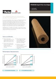
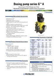
Description<br />
Microcontroller operated <strong>Flow</strong> <strong>Meter</strong> for <strong>gases</strong> such as <strong>air</strong>, <strong>compressed</strong><br />
<strong>air</strong>, oxygen, nitrogen, argon, carbon dioxide, methane/natural gas<br />
and hydrogen. The <strong>FC01</strong>-<strong>CA</strong> is particularly suited to consumption<br />
measurement and leakage detection in <strong>compressed</strong> <strong>air</strong> systems. It is<br />
suitable for use with calorimetric monitoring heads.<br />
Please note for use with carbon dioxide and argon that measurement is<br />
only possible with adapters TP-01 through TP-04.<br />
rail-mounted version<br />
1<br />
front panel mounted version<br />
<strong>FC01</strong>-<strong>CA</strong><br />
surface mounted version<br />
Features<br />
• Menu driven (keypads)<br />
• LC display (2 x 16 digits) can show:<br />
- actual operating flow velocity/standard flow velocity, operating<br />
volume flow/standard volume flow, mass flow, medium<br />
temperature;<br />
- bargraph status indication of limit contacts, actual flow rate/<br />
quantity or medium temperature;<br />
- directions for parameter assignment, configuration, diagnostics<br />
and error correction;<br />
- base value indication<br />
• Two scalable analogue outputs<br />
• Minimum/maximum memory of flow velocity and temperature<br />
• Two freely selectable limit contacts<br />
• Volume- or mass flow dependent pulse output<br />
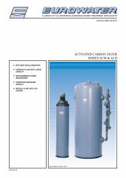
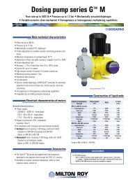
Dimensions<br />
<strong>FC01</strong>-<strong>CA</strong> (rail-mounted housing)<br />
75<br />
2.95<br />
100<br />
56<br />
3.94 2.20<br />
<strong>FC01</strong>-FH-<strong>CA</strong> (surface mounted housing)<br />
60<br />
2.36<br />
140<br />
5.51<br />
103<br />
71<br />
4.06<br />
2.80<br />
M16<br />
Ordering information<br />
Type<br />
<strong>FC01</strong>-<strong>CA</strong><br />
<strong>FC01</strong>-FH-<strong>CA</strong><br />
<strong>FC01</strong>-ST-<strong>CA</strong><br />
<strong>Flow</strong> <strong>Meter</strong> with software for mass measurement of <strong>gases</strong>,<br />
rail mounted<br />
<strong>Flow</strong> <strong>Meter</strong> with software for mass measurement of <strong>gases</strong>,<br />
surface mounted<br />
<strong>Flow</strong> <strong>Meter</strong> with software for mass measurement of <strong>gases</strong>,<br />
front panel mounted<br />
Input voltage<br />
U1 DC 19...32 V<br />
Signal outputs<br />
R2 2 relay outputs (2 limit values)<br />
T4 4 transistor outputs (2 limit values + 2 status<br />
or 2 limit values + 1 status + 1 pulse output)<br />
Analogue outputs<br />
V1 0/1-5 Volt<br />
V2 0/2-10 Volt<br />
C1 0/4-20 mA (self-powered, galvanically isolated)<br />
<strong>FC01</strong>-<strong>CA</strong> - U1 R2 V1 ordering example<br />
125<br />
4.92<br />
ø4.5<br />
M16<br />
.177 mounting holes<br />
<strong>FC01</strong>-ST-<strong>CA</strong> (front panel mounted housing)<br />
96<br />
3.78<br />
144<br />
5.67<br />
M<br />
M<br />
140<br />
5.51<br />
mounting hole<br />
DIN 43700<br />
92<br />
3.62<br />
140<br />
5.51<br />
82<br />
3.23<br />
4<br />
.158<br />
This is a metric design and millimeter dimensions take precedence ( mm )<br />
inch<br />
www.flowvision-gmbh.de<br />
2010<br />
29
<strong>Flow</strong> <strong>Meter</strong> <strong>FC01</strong>-<strong>CA</strong> (<strong>compressed</strong> <strong>air</strong>/<strong>gases</strong>)<br />
1<br />
<strong>Flow</strong> <strong>Meter</strong> <strong>FC01</strong>-<strong>CA</strong><br />
General data<br />
Monitoring heads applicable in<br />
Measuring functions<br />
Display<br />
Parameter assignment, calibration by:<br />
Technical Data<br />
with CSP monitoring head and<br />
sensor adapter TP/ball valve BV<br />
with CST/CSF monitoring head (2)<br />
<strong>air</strong>, <strong>compressed</strong> <strong>air</strong>, oxygen, argon, carbon dioxide, methane/natural gas,<br />
nitrogen, hydrogen, other <strong>gases</strong> on request<br />
operating/standard flow velocity, operating/standard volume flow rate,<br />
mass flow, medium temperature, totalized flow rate<br />
2 x 16 digit LC display<br />
keypads<br />
Temperature range (electronic control unit) in circulating <strong>air</strong> +10 °C ... +50 °C/+50 °F … +122 °F *)<br />
Standard flow velocity (unit = Nm/s) and standard volume flow rate (unit = Nm 3 /h) are related to 1013 mbar/14.7 psi and 0 °C/+32 °F<br />
Operating flow velocity and operating volume flow rate are related to set pressure and measured temperature<br />
Electrical data<br />
Input voltage DC 24 V (19 ... 32 V)<br />
Power consumption DC 200 mA **)<br />
Analogue outputs (flow and temperature)<br />
0/4-20 mA or 0/2-10 V or 0/1-5 V<br />
Signal outputs 2 relay outputs (2 limit values) 2 SPDT contacts AC/DC 50 V / 1 A / 50 W<br />
4 transistor outputs (2 limit values + 2<br />
open collector outputs DC 36 V / 150 mA / 1,5 W<br />
status, or 2 limit values + 1 status + 1<br />
pulse output)<br />
<strong>Flow</strong> measurement<br />
measurement range<br />
Measuring range 0...68 Nm/s (medium <strong>air</strong>)<br />
in TP-02 0 - 77 (109) Nm 3 /h (1)<br />
(display range 0...100 Nm/s)<br />
in TP-03 0 - 120 (170) Nm 3 /h (1)<br />
see table flow<br />
Zero adjustment possible for smallest volume flow quantities<br />
(next page)<br />
Low flow suppression (adjustable, 0% … 10 % of measuring in TP-04 0 - 197 (280) Nm 3 /h (1)<br />
(2)<br />
in TP-01 0 - 50 (70) Nm 3 /h (1)<br />
range final value)<br />
in TP-05 0 - 308 (439) Nm 3 /h (2)<br />
in TP-06 0 - 480 (685) Nm 3 /h (2)<br />
Accuracy (5) 3 % ... 50 % of measuring range ^= 2 ... 34 Nm/s ±3 % of measured value ±0,1 % of MRFV ±5 % of measured value ±0,5 % of MRFV<br />
50 % ... 100 % of measuring range ^= 34 ... 68 Nm/s ±4 % of measured value ±1 % of MRFV ±7 % of measured value ±1 % of MRFV<br />
Repeatability (5 % MRFV ... 100 % MRFV) (3)<br />
±1 % of measured value ±0,5 % of measuring range final value<br />
Temperature drift (4) (of electronic control unit)<br />
0,05 %/°K/measuring range final value<br />
Pressure error<br />
±0,5 %/bar|14.5 psi of measured value<br />
Response time (step function)<br />
< 1 s<br />
Temperature measurement<br />
Measuring range -40 °C ... +130 °C/-40 °F … +266 °F<br />
Accuracy<br />
±1 % of measuring range<br />
Mechanical data (electronic control unit)<br />
Degree of<br />
rail-mounted:<br />
IP20<br />
protection<br />
surface mounted:<br />
IP65<br />
front panel mounted:<br />
IP65<br />
Materials rail-mounted: acrylic vinyl/ styrene/ polycarbonate; heat sink aluminium<br />
surface mounted:<br />
aluminium Acryl<br />
front panel mounted:<br />
aluminium, black coated; display polyester foil<br />
Housing dimension (LxWxH)<br />
see dimension diagram (previous page)<br />
Mass rail-mounted: 485 g<br />
surface mounted:<br />
1250 g<br />
front panel mounted:<br />
900 g<br />
Cables voltage supply 3x0,75 mm 2 (AWG 18)<br />
to monitoring head LifYCY 4x2x0,2 mm 2 (AWG 24)<br />
analogue outputs 2 x LifYCY 2x0,25 mm 2 (AWG 24)<br />
limit value output 2 x LifYCY 3x0,38 mm 2 (AWG 22)<br />
Max. cable length to monitoring head<br />
200 m<br />
*) with output C1 the max. admissible ambient temperature for the rail-mounted version is limited to +40 °C/+104 °F<br />
**) with output C1, power consumption may be up to 300 mA ± 10 %<br />
(1) measuring ranges for: methan/natural gas: argon and carbon dioxide: hydrogen:<br />
TP-01(1/2 in) 36 Nm /h (54 Nm /h) 3 3 3,0 - 50 Nm /h (70 Nm /h) 3 3 29,0 Nm /h (62,3 Nm /h)<br />
3 3<br />
TP-02 (3/4 in) 56 Nm /h (84 Nm /h) 3 3 4,0 - 70 Nm /h (110 Nm /h) 3 3 45,2 Nm /h (97,3 Nm /h)<br />
3 3<br />
TP-03/BV-03 (1 in) 88 Nm /h (132 Nm /h) 3 3 5,0 - 120 Nm /h (176 Nm /h) 3 3 70,7 Nm /h (152 Nm /h)<br />
3 3<br />
TP-04/BV-04 (1.1/4 in) 144 Nm /h (217 Nm /h) 3 3 5,0 - 195 Nm /h (289 Nm /h) 3 3 116 Nm /h (249 Nm /h)<br />
3 3<br />
TP-05/BV-05 (1.1/2 in) 226 Nm /h (339 Nm /h) 3 3 181 Nm /h (389 Nm /h)<br />
3 3<br />
TP-06/BV-06 (2 in) 353 Nm /h (530 Nm /h) 3 3 TP-01 … TP-04 only 283 Nm /h (608 Nm /h)<br />
3 3<br />
CSF and CST monitoring heads up to 141.343 Nm /h (212.000 Nm /h) 3 3 113.112 Nm /h (243.144 Nm /h)<br />
3 3<br />
(2) not released for carbon dioxide (CO 2<br />
) and argon (Ar)<br />
(3) of the set value, at constant temperature and flow conditions and stable thermal conductivity<br />
(4) warm-up time to full accuracy: 15 minutes<br />
(5) the accuracy values were determined under ideal conditions: - symmetrical complete flow profile<br />
- correct mounting in the pipe<br />
- inlets and outlets according to EN ISO 5167-1<br />
MRFV = measuring range final value<br />
30 2010 www.flowvision-gmbh.de
<strong>Flow</strong> <strong>Meter</strong> <strong>FC01</strong>-<strong>CA</strong> (<strong>compressed</strong> <strong>air</strong>/<strong>gases</strong>)<br />
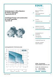
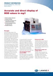
Block diagram<br />
Connection diagram<br />
Sensor<br />
interface<br />
Calorimetric<br />
monitoring<br />
head<br />
Power supply DC/DC<br />
Microcontroller<br />
system<br />
User<br />
interface 1<br />
1 2 3<br />
1<br />
2<br />
3<br />
4<br />
5<br />
6<br />
1 2 3 1 2 3 4<br />
XV XSK<br />
XTF XSF<br />
7<br />
8<br />
9<br />
10<br />
1<br />
User<br />
interface 2<br />
1<br />
2<br />
3<br />
XAS XAO XAH<br />
4<br />
5<br />
6<br />
7<br />
8<br />
1<br />
2<br />
3<br />
4<br />
5<br />
6<br />
7<br />
8<br />
1<br />
2<br />
3<br />
4<br />
5<br />
6<br />
7<br />
8<br />
Keyboard and display<br />
Input voltage:<br />
Keyboard/display:<br />
User interface 1:<br />
User interface 2:<br />
Controller system:<br />
Sensor interfaces:<br />
DC 19 … 32 V<br />
keypads<br />
LC display<br />
2 x 16 digits<br />
relay outputs: 2 limit values<br />
transistor outputs: 2 limit values +<br />
1 error indication +<br />
1 busy or quantity dependent<br />
pulse output (software selected)<br />
analogue outputs<br />
current or voltage<br />
signal processing<br />
I/O - controlling<br />
monitoring<br />
parameter memory<br />
calorimetric monitoring head<br />
Wire size:<br />
Stripping length:<br />
Clamping screw:<br />
Contact material:<br />
XV: current supply<br />
XSK: calorimetric monitoring head<br />
XTF: keyboard release<br />
XSF: not released for user<br />
XAS: not released for user<br />
XAO: analogue outputs<br />
XAH: signal outputs<br />
0.14 mm 2 to 1.5 mm 2 single or finely stranded conductor<br />
6.5 mm<br />
M2 (nickel-plated brass)<br />
pre-tinned tin bronze<br />
<strong>Flow</strong> measurement range (referring to the medium <strong>air</strong>)<br />
The flow measurement range is determined by the inner pipe diameter<br />
(see table). It can be calculated with the following equation:<br />
Q = V N<br />
x A R<br />
Q (Nm 3 /h) - flow quantity<br />
V N<br />
(m/h) - average standard velocity<br />
A R<br />
(m 2 ) - inner pipe cross section<br />
Setting range for inner pipe diameter:<br />
Velocity range:<br />
10.0 mm ... 999.9 mm/<br />
.394 in. … 39.4 in.<br />
0...68 Nm/s (100 Nm/s)<br />
inner pipe measuring display inner pipe measuring display<br />
diameter range range diameter range range<br />
D in mm in Nm /h 3 in Nm /h 3 D in mm in Nm /h 3 in Nm /h<br />
3<br />
20 76 113 200 7690 11309<br />
30 173 254 250 12016 17671<br />
40 307 452 300 17303 25446<br />
50 480 706 400 30762 4523<br />
60 692 1017 500 48066 70685<br />
70 942 1385 600 69215 101787<br />
80 1230 1809 700 94210 138544<br />
90 1557 2290 800 123049 180955<br />
100 1922 2827 900 155734 229021<br />
150 4325 6361 1000 192265 282743<br />
www.flowvision-gmbh.de<br />
2010<br />
31
8<br />
8<br />
8<br />
8<br />
8<br />
1<br />
2<br />
3<br />
4<br />
5<br />
6<br />
7<br />
1<br />
2<br />
1<br />
3<br />
4<br />
2<br />
3<br />
5<br />
4<br />
6<br />
5<br />
7<br />
6<br />
8<br />
7<br />
9<br />
1<br />
2<br />
2<br />
3<br />
3<br />
4<br />
1<br />
5<br />
2<br />
6<br />
3<br />
7<br />
1<br />
2<br />
3<br />
4<br />
5<br />
6<br />
7<br />
1<br />
2<br />
1<br />
3<br />
2<br />
4<br />
3<br />
5<br />
4<br />
6<br />
5<br />
7<br />
6<br />
8<br />
7<br />
9<br />
1<br />
2<br />
2<br />
3<br />
3<br />
4<br />
1<br />
5<br />
2<br />
6<br />
3<br />
7<br />
8<br />
8<br />
8<br />
8<br />
8<br />
8<br />
<strong>Flow</strong> <strong>Meter</strong> <strong>FC01</strong>-<strong>CA</strong> (<strong>compressed</strong> <strong>air</strong>/<strong>gases</strong>)<br />
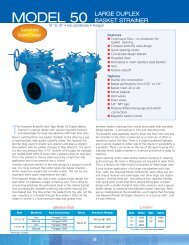
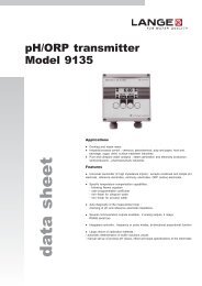
Connection diagrams<br />
1<br />
<strong>FC01</strong>-<strong>CA</strong> with relay outputs<br />
3x0.75 mm (+24V) brown<br />
/LIM2<br />
LIM2COM LifYCY 3x0.38 mm 2 *<br />
LIM2<br />
SGNDL2<br />
/LIM1<br />
LifYCY 3x0.38 mm 2 * signal outputs<br />
}<br />
LIM1COM<br />
LIM1<br />
SGNDL1<br />
R(Tdiff)-HI pink<br />
R(Tdiff)-LO grey<br />
ANA2GND LifYCY 2x0.25 mm 2 *<br />
SGND black<br />
ANAO2<br />
SGNDA2<br />
LifYCY 4x2x0.2 mm 2<br />
IS<br />
red<br />
SGNDA1<br />
blue<br />
ANA1GND LifYCY 2x0.25 mm 2 * analogue outputs **<br />
}<br />
AGND<br />
C1, V1, V2<br />
calorimetric<br />
R(Tref)-LO white<br />
ANAO1<br />
monitoring head<br />
R(Tref)-HI brown<br />
R(HEIZ)-H I green<br />
yellow<br />
R(HEIZ)-LO * recommended<br />
** apply shield on one side only<br />
recommended:<br />
(0V) blue<br />
GND yellow/green<br />
power supply<br />
1 4<br />
10<br />
3<br />
2<br />
1<br />
XV XSK XTF XSF<br />
XAS XAO XAH<br />
<strong>FC01</strong>-<strong>CA</strong> with transistor outputs<br />
3x0.75 mm<br />
R(Tdiff)-HI<br />
(+24V) brown<br />
pink<br />
R(Tdiff)-LO grey<br />
SGND black<br />
LifYCY 4x2x0.2 mm 2<br />
IS<br />
red<br />
AGND blue<br />
calorimetric<br />
R(Tref)-LO white<br />
monitoring head<br />
R(Tref)-HI brown<br />
R(HEIZ)-H I green<br />
R(HEIZ)-LO yellow<br />
recommended:<br />
(0V) blue<br />
GND yellow/green<br />
power supply<br />
1 4<br />
1 2 3<br />
10<br />
XV XSK XTF XSF<br />
XAS XAO XAH<br />
C/ ** +<br />
LIM1<br />
LIM1 E/ -<br />
LIM2 C/ +<br />
LIM2<br />
BUSY/PULSE<br />
E/ -<br />
C/+<br />
LifYCY 4x2x0.2 mm 2 *<br />
BUSY/PULSE E/ -<br />
ERROR C/ +<br />
ERROR E/ -<br />
ANA2GND<br />
ANAO2<br />
SGNDA2<br />
SGNDA1<br />
ANA1GND<br />
ANAO1<br />
SGND<br />
LifYCY 2x0.25 mm 2 *<br />
signal outputs<br />
LifYCY 2x0.25 mm 2 *<br />
analogue outputs ***<br />
}V1, V2, C1<br />
* recommended<br />
** E/ - emitter terminal<br />
C/ + collector terminal<br />
*** apply shield on one side only<br />
<strong>FC01</strong>-<strong>CA</strong> - Recommended connection of pulse output<br />
Electronic signal processing<br />
Electromagnetic pulse counter<br />
XAS XAO XAH<br />
XAS XAO XAH<br />
1<br />
2<br />
3<br />
4<br />
5<br />
6<br />
7<br />
1<br />
2<br />
3<br />
4<br />
5<br />
6<br />
7<br />
1<br />
2<br />
3<br />
4<br />
5<br />
6<br />
7<br />
1<br />
2<br />
3<br />
4<br />
5<br />
6<br />
7<br />
1<br />
2<br />
3<br />
4<br />
5<br />
6<br />
7<br />
1<br />
2<br />
3<br />
4<br />
5<br />
6<br />
7<br />
8<br />
Zener voltage<br />
i C<br />
t L t ON t<br />
U C<br />
U V<br />
i L 10 mA<br />
U V<br />
U C<br />
i C<br />
U V
<strong>FC01</strong>-<strong>CA</strong> - Sensor adapter TP|Ball valve BV<br />
Description<br />
Sensor adapter TP-... / Ball valve BV-...<br />
Sensor adapters TP and BV facilitate correct positioning and exchange<br />
of CSP monitoring heads, FC03 or FS10 in pipes with process<br />
connection DN 15...DN 50.<br />
Ball valve BV enables pressure-free installation and removal of CSP<br />
monitoring heads, <strong>Flow</strong> <strong>Meter</strong> FC03 and <strong>Flow</strong> Monitor FS10 simply by<br />
closing the input and output pipe. The measuring points are suited to<br />
temporary measurements; after completion of the measuring cycle they<br />
can be closed by means of blanking plugs.<br />
1<br />
TP-...<br />
BV-...<br />
Features<br />
Ordering information<br />
• Correct positioning of the sensor<br />
• Ease of sensor replacement<br />
• Measuring point can be closed if not used<br />
• Sensor adapter available as screw-in or welding type<br />
• Ball valve also serves as a shutoff valve (both input and output)<br />
• Carbon dioxide (CO 2<br />
) and argon (Ar): only approved for TP-01 ... 04<br />
Type<br />
BV<br />
ball valve with internal thread<br />
Process connection/Nominal size<br />
03 DN 25 G1 internal thread length: 88 mm/3.46 in.<br />
04 DN 32 G1 1/4 internal thread length: 100 mm/3.94 in.<br />
05 DN 40 G1 1/2 internal thread length: 110 mm/4.33 in.<br />
06 DN 50 G2 internal thread length: 131 mm/5.16 in.<br />
Material of the area exposed to medium<br />
M3 nickel plated brass, Delrin seal<br />
BV - 03 M3 ordering example<br />
Ordering information<br />
Accessories<br />
Type<br />
TP<br />
Sensor adapter with internal thread<br />
Process connection/Nominal size<br />
01 DN 15 G 1/2 internal thread length: 50 mm/1.97 in.<br />
02 DN 20 G 3/4 internal thread length: 64 mm/2.52 in.<br />
03 DN 25 G1 internal thread length: 78 mm/3.07 in.<br />
04 DN 32 G1 1/4 internal thread length: 94 mm/3.70 in.<br />
05 DN 40 G1 1/2 internal thread length: 110 mm/4.33 in.<br />
06 DN 50 G2 internal thread length: 138 mm/5.43 in.<br />
Material of the area exposed to medium<br />
M1 stainless steel 1.4571/AISI 316Ti PN 315 bar/4570 psi<br />
M3 brass (not TP-03..)<br />
PN 25 bar/363 psi<br />
M5 red brass (only TP-03..)<br />
PN 16 bar/232 psi<br />
Description<br />
Ref. No.<br />
Blanking plug, brass, with O ring<br />
0Z121Z000186<br />
Union nut, brass Y 306 901 01<br />
Blanking plug, stainless steel 1.4571/AISI 316 Ti,<br />
with viton O ring<br />
0Z121Z000187<br />
Union nut, stainless steel Y 306 901 03<br />
TP - 01 M3 ordering example<br />
Ordering information<br />
Type<br />
TP<br />
Sensor adapter with welding nipples<br />
Process connection/Nominal size<br />
01 DN 15 dia.d: 16 mm/.630 in. length: 80 mm/3.15 in.<br />
02 DN 20 dia.d: 20 mm/.787 in. length: 70 mm/2.76 in.<br />
03 DN 25 dia.d: 25 mm/.984 in. length: 80 mm/3.15 in.<br />
04 DN 32 dia.d: 32 mm/1.26 in. length: 100 mm/3.94 in.<br />
05 DN 40 dia.d: 40 mm/1.57 in. length: 110 mm/4.33 in.<br />
06 DN 50 dia.d: 50 mm/1.97 in. length: 140 mm/5.51 in.<br />
Material of the area exposed to medium<br />
M1 stainless steel 1.4571/AISI 316Ti<br />
Process connection<br />
SA welded connection<br />
TP - 01 M1 - SA ordering example<br />
www.flowvision-gmbh.de<br />
2010<br />
33
<strong>FC01</strong>-<strong>CA</strong> - Sensor adapter TP|Ball valve BV<br />
Dimensions<br />
1<br />
TP-… Sensor adapter with internal thread<br />
SW<br />
G<br />
ød<br />
t<br />
L<br />
t<br />
SW = width across flats<br />
Material stainless steel (-M1):<br />
Material brass (-M3):<br />
Material red brass (-M5):<br />
Type<br />
TP-01 …<br />
TP-02 …<br />
TP-03 …<br />
TP-04 …<br />
TP-05 …<br />
TP-06 …<br />
PN 315 bar / 4570 psi<br />
PN 25 bar / 363 psi<br />
PN 16 bar / 232 psi<br />
DN<br />
mm<br />
15<br />
20<br />
25<br />
32<br />
40<br />
50<br />
in.<br />
.591<br />
.787<br />
.984<br />
1.26<br />
1.57<br />
1.97<br />
dia. d<br />
mm<br />
16<br />
20<br />
25<br />
32<br />
40<br />
50<br />
in.<br />
.630<br />
.787<br />
.984<br />
1.26<br />
1.57<br />
1.97<br />
G<br />
in.<br />
1/2"<br />
3/4"<br />
1"<br />
11/4"<br />
11/2"<br />
2"<br />
t L<br />
mm in. mm in.<br />
11<br />
12<br />
14<br />
15<br />
15<br />
19<br />
.433<br />
.472<br />
.551<br />
.591<br />
.591<br />
.748<br />
50<br />
64<br />
78<br />
94<br />
110<br />
138<br />
1.97<br />
2.52<br />
3.07<br />
3.70<br />
4.33<br />
5.43<br />
SW<br />
mm in.<br />
27<br />
32<br />
40<br />
50<br />
55<br />
70<br />
1.06<br />
1.26<br />
1.57<br />
1.97<br />
2.16<br />
2.76<br />
TP-..M1-SA Sensor adapter with welding nipples<br />
SW<br />
øD<br />
ød<br />
PN 315 bar / 4570 psi<br />
t<br />
L<br />
t<br />
Type<br />
TP-01M1-S A<br />
TP-02M1-S A<br />
TP-03M1-S A<br />
TP-04M1-S A<br />
TP-05M1-S A<br />
TP-06M1-S A<br />
DN<br />
mm<br />
15<br />
20<br />
25<br />
32<br />
40<br />
50<br />
in.<br />
.591<br />
.787<br />
.984<br />
1.26<br />
1.57<br />
1.97<br />
dia. d<br />
mm<br />
16<br />
20<br />
25<br />
32<br />
40<br />
50<br />
in.<br />
.630<br />
.787<br />
.984<br />
1.26<br />
1.57<br />
1.97<br />
dia. D<br />
t<br />
mm in. mm in. mm in.<br />
21.3 .839<br />
26.9 1.06<br />
33.7 1.33<br />
15<br />
15<br />
15<br />
.591<br />
.591<br />
.591<br />
80 3.15<br />
70 2.76<br />
80 3.15<br />
42.4 1.67<br />
48.3 1.90<br />
60.3 2.37<br />
15<br />
15<br />
15<br />
.591 100 3.94<br />
.591 110 4.33<br />
.591 140 5.51<br />
L<br />
SW<br />
mm<br />
27<br />
32<br />
40<br />
50<br />
55<br />
70<br />
in.<br />
1.06<br />
1.26<br />
1.57<br />
1.97<br />
2.16<br />
2.76<br />
BV-...M3 Ball valve with internal thread<br />
A<br />
ød<br />
G<br />
SW<br />
H<br />
L<br />
t<br />
PN 25 bar / 363 psi<br />
Type<br />
BV-03M3<br />
BV-04M3<br />
BV-05M3<br />
BV-06M3<br />
DN<br />
mm<br />
25<br />
32<br />
40<br />
50<br />
in.<br />
.984<br />
1.26<br />
1.57<br />
1.97<br />
mm<br />
dia. d<br />
25<br />
32<br />
40<br />
50<br />
in.<br />
.984<br />
1.26<br />
1.57<br />
1.97<br />
G<br />
in.<br />
1"<br />
11/4"<br />
11/2"<br />
2"<br />
21<br />
24<br />
24<br />
28<br />
t<br />
.827<br />
.945<br />
.945<br />
1.10<br />
L<br />
mm in. mm in.<br />
88 3.46<br />
100 3.94<br />
110 4.33<br />
131 5.16<br />
mm<br />
41<br />
50<br />
54<br />
70<br />
SW<br />
in.<br />
1.61<br />
1.97<br />
2.13<br />
2.76<br />
mm<br />
59<br />
65<br />
77<br />
85<br />
H<br />
in.<br />
2.32<br />
2.56<br />
3.03<br />
3.35<br />
A<br />
mm<br />
115<br />
115<br />
150<br />
150<br />
in.<br />
4.53<br />
4.53<br />
5.91<br />
5.91<br />
This is a metric design and millimeter dimensions take precedence ( mm )<br />
inch<br />
34 2010 www.flowvision-gmbh.de
2.52<br />
.551<br />
.717<br />
<strong>FC01</strong>-<strong>CA</strong> | Monitoring head CSP-11<br />
Description<br />
Monitoring head CSP<br />
Calorimetric plug-in type monitoring head for sensor adapter TP/BV and<br />
flow meter <strong>FC01</strong>-<strong>CA</strong>, suitable for <strong>compressed</strong>-<strong>air</strong> applications and for<br />
measurement of <strong>gases</strong>.<br />
1<br />
Features<br />
• Ease of installation<br />
• Small physical size<br />
• Medium temperature range: -40 °C ... +130 °C/-40 °F … +266 °F<br />
• Material: stainless steel 1.4571/AISI 316 Ti<br />
• Sealing: Viton O ring<br />
CSP-11<br />
Ordering information<br />
Technical data<br />
Type No.<br />
CSP plug-in type monitoring head with calorimetric sensors<br />
Process connection<br />
11 plug-in type<br />
Medium<br />
A <strong>air</strong> (standard)<br />
Material of areas exposed to medium<br />
M1 stainless steel 1.4571/AISI 316 Ti (standard)<br />
Length of shank/thread<br />
L05 18.2 mm (standard)<br />
Electrical connection<br />
E10 round connector with tinned contacts<br />
(plug and cable to order separately)<br />
Certification<br />
T0 without certificate (standard)*)<br />
Specification of medium<br />
xxx<br />
CSP - 11 A M1 L05 E10 T0 - ... ordering example<br />
*) for detailed information please see section 0.<br />
Dimensions<br />
retention slot<br />
Type of head<br />
Shank diameter<br />
Length of shank<br />
Length of sensor<br />
Suitable for<br />
plug-in type<br />
18 mm/.709 in.<br />
18.2 mm/.717 in.<br />
14 mm/.551 in.<br />
<strong>air</strong>, <strong>compressed</strong> <strong>air</strong>, nitrogen, oxygen,<br />
argon, carbon dioxide, methane, hydrogen<br />
and other <strong>gases</strong> (please enquire)<br />
Temperature range *) -40 °C ... +130 °C/-40 °F … +266 °F<br />
(of gas)<br />
Temperature drift<br />
of monitoring head<br />
±< 0.05 %/°K/measuring range<br />
(in the range between +20°C … +80°C/<br />
+68 °F … +176 °F)<br />
Measuring ranges (<strong>air</strong>) in TP01 0 - 50 Nm 3 /h<br />
in TP02 0 - 77 Nm 3 /h<br />
in TP03 0 - 120 Nm 3 /h<br />
in TP04 0 - 197 Nm 3 /h<br />
in TP05 0 - 308 Nm 3 /h<br />
in TP06 0 - 480 Nm 3 /h<br />
Pressure resistance (1) 100 bar/1450 psi<br />
Degree of protection<br />
Material<br />
housing<br />
O ring<br />
connector (2) : IP67<br />
stainless steel 1.4571/AISI 316 Ti<br />
laser welded<br />
Viton<br />
Cable to LifYCY 4x2x0.2 mm 2 (AWG 24)<br />
electronic control unit<br />
ø18<br />
.709<br />
ø24<br />
.945<br />
8<br />
.315<br />
(1)<br />
Admissible operating pressure DIN 2401, measured at max. temperature<br />
(= max. medium temperature)<br />
(2)<br />
with mating connector<br />
*)<br />
max. +85 °C in the connector area<br />
64<br />
18.2 14<br />
ø20<br />
.787<br />
This is a metric design and millimeter dimensions take precedence ( mm )<br />
inch<br />
www.flowvision-gmbh.de<br />
2010<br />
35
.709<br />
<strong>FC01</strong>-<strong>CA</strong> | Cable types and accessories (CSP-11)<br />
Cable types 15/18 with connectors<br />
Description<br />
1<br />
Cable between <strong>Flow</strong> <strong>Meter</strong> <strong>FC01</strong>-xxx and calorimetric monitoring head<br />
type CSP.<br />
• Connection to monitoring head by means of 8-pole round connector<br />
• Connection to <strong>FC01</strong>-xxx by means of 10-pole clamping connector<br />
(XSK)<br />
Do + Ka Typ 15<br />
Do + Ka Typ 18<br />
Do + Ka Typ 15-ST<br />
Do + Ka Typ 18-ST<br />
Technical data<br />
Accessories<br />
Cable type 15 and 15-ST<br />
Features: highly flexible, p<strong>air</strong>ed, fully shielded,<br />
electrical and thermal properties at +20 °C/+68 °F<br />
Conductor resistance:<br />
Insulation resistance:<br />
Operating voltage:<br />
Withstand voltage:<br />
Max. load:<br />
92 Ω/km<br />
20 MΩ x km<br />
250 V<br />
500 V<br />
2 A<br />
Temperature range: -10 °C ... +80 °C/+14 °F … +176 °F<br />
(processing and operation)<br />
-30 °C ... +80 °C/-22 ° F … +176 °F<br />
(transport and storage)<br />
Cable type 18 and 18-ST<br />
Features: non-halogenous, highly flexible, cold- and heat resistant,<br />
p<strong>air</strong>ed, fully shielded, electrical and thermal properties<br />
at +20 °C/+68 °F<br />
Conductor resistance:<br />
Insulation resistance:<br />
Operating voltage:<br />
Withstand voltage:<br />
Max. load:<br />
80 Ω/km<br />
1200 MΩ x km<br />
300 V<br />
1500 V<br />
3 A<br />
Temperature range: -50 °C ... +180 °C/-58 °F … +356 °F<br />
8-pole round connector<br />
(without cable, for individual wiring by customer)<br />
0Z112Z003124<br />
ø18<br />
50<br />
1.97<br />
10-pole clamping connector for cable types 15 and 18<br />
(without cable, for individual wiring by customer)<br />
0Z112Z000167<br />
10-pole clamping connector for cable types 15-ST and 18-ST<br />
(without cable, for individual wiring by customer)<br />
0Z112Z000205<br />
Ordering information<br />
Typ between calorimetric monitoring heads CST and <strong>FC01</strong>-<strong>CA</strong>, <strong>FC01</strong>-FH-<strong>CA</strong><br />
Do + Ka type 15 PVC insulated cable, type LifYCY 4x2x0.2 mm 2 (AWG 24)<br />
8-pole round connector + 10-pole clamping connector<br />
Do + Ka type 18 silicone insulated cable, type 4x2x0.2 mm 2 (AWG 24)<br />
8-pole round connector + 10-pole clamping connector<br />
Available cable lengths<br />
...m 2 m, 3 m, 5 m, 8 m, 10 m, 15 m, 20 m, 25 m,<br />
30 m, 40 m, 50 m, 60 m, 70 m, 80 m, 90 m,<br />
100 m, 110 m, 120 m, 130 m, 140 m, 150 m,<br />
160 m, 170 m, 180 m, 190 m, 200 m<br />
Do + Ka type 15 - 2 m ordering example<br />
Reducing piece<br />
from G3/4 to G1/2<br />
This Material: is a metric stainless design and steel millimeter 1.4571/AISI dimensions Ti take 316 precedence ( mm )<br />
0Z032Z000149<br />
inch<br />
SW30<br />
24<br />
Standard warranty 1.18 cover will be invalidated .945 if the correct <strong>Flow</strong>Vision<br />
monitoring head/control unit connecting cable is not used.<br />
Type between calorimetric monitoring heads CST and <strong>FC01</strong>-ST-<strong>CA</strong><br />
Do + Ka type 15-ST PVC insulated cable, type LifYCY 4x2x0.2 mm 2 (AWG 24)<br />
8-pole round connector + 10-pole clamping connector<br />
Do + Ka type 18-ST silicone insulated cable, type 4x2x0.2 mm 2 (AWG 24)<br />
8-pole round connector + 10-pole clamping connector<br />
Available cable lengths<br />
...m 2 m, 3 m, 5 m, 8 m, 10 m, 15 m, 20 m, 25 m,<br />
30 m, 40 m, 50 m, 60 m, 70 m, 80 m, 90 m,<br />
100 m, 110 m, 120 m, 130 m, 140 m, 150 m,<br />
160 m, 170 m, 180 m, 190 m, 200 m<br />
G1/2A<br />
G3/4A<br />
Do + Ka type 15-ST - 2 m<br />
ordering example<br />
36 2010 www.flowvision-gmbh.de
1.42<br />
.551<br />
<strong>FC01</strong>-<strong>CA</strong> | Monitoring head CST-11<br />
Description<br />
Thread-mounted calorimetric monitoring head<br />
Thread-mounted calorimetric monitoring head for flow <strong>Meter</strong> <strong>FC01</strong>-<strong>CA</strong>,<br />
suitable for <strong>compressed</strong> <strong>air</strong> applications.<br />
1<br />
Features<br />
• Suitable for installation in welding sleeves<br />
• Medium temperature: -40 °C ... +130 °C/-40 °F … +266 °F<br />
• Material: stainless steel 1.4571/AISI 316 Ti,<br />
or Hastelloy alloy C4/2.4610<br />
• Not suitable for carbon dioxide and argon!<br />
CST-11<br />
Ordering information<br />
Technical data<br />
Type No.<br />
CST Thread-mounted monitoring head with calorimetric sensors<br />
Process connection<br />
11 thread size G1/2A<br />
Medium<br />
A <strong>air</strong><br />
Material of areas exposed to medium<br />
M1 stainless steel 1.4571/AISI 316 Ti (standard)<br />
M2 nickel-based alloy Hastelloy alloy C4/2.4610<br />
Length of shank/thread<br />
L10 36 mm (standard)<br />
Electrical connection<br />
E10 round connector with tinned contacts<br />
(plug and cable to order separately)<br />
Certification<br />
T0 without certificate (standard) *)<br />
Specification of medium<br />
xxx<br />
CST - 11 A M1 L10 E10 T0 - ... ordering example<br />
*) for detailed information please see section 0.<br />
Dimensions of round connector<br />
Type of head<br />
Thread<br />
Length of shank<br />
Length of sensor<br />
Suitable for<br />
thread-mounted<br />
G1/2A<br />
36 mm/1.42 in.<br />
14 mm/.551 in.<br />
<strong>air</strong>, <strong>compressed</strong> <strong>air</strong>, nitrogen, oxygen,<br />
methane, hydrogen and other <strong>gases</strong><br />
(please enquire)<br />
Temperature range *) -40 °C ... +130 °C/-40 °F … +266 °F<br />
(of gas)<br />
Temperature drift<br />
of monitoring head<br />
Measuring ranges:<br />
<strong>Flow</strong> velocity range:<br />
Pressure resistance (1)<br />
Degree of protection<br />
Material<br />
± < 0.05 %/°K/measuring range<br />
(in the range between +20 °C … +80 °C/<br />
+68 °F … +176 °F)<br />
Average standard flow velocity x pipe<br />
cross section<br />
0 - 68 (100) Nm/s<br />
100 bar / 1450 psi<br />
connector (2) : IP67<br />
stainless steel 1.4571/AISI 316 Ti<br />
Hastelloy C4<br />
Cable to LifYCY 4x2x0.2 mm 2 (AWG 24)<br />
electronic control unit<br />
(1)<br />
Admissible operating pressure DIN 2401, measured at max. temperature<br />
(= max. medium temperature)<br />
(2)<br />
with mating connector<br />
*)<br />
max. +85 °C in the connector area<br />
G1/2A<br />
14<br />
B<br />
øA<br />
øA<br />
B<br />
36<br />
mm<br />
inch<br />
mm<br />
inch<br />
G1/2A<br />
18 .709<br />
10 .394<br />
SW27<br />
1.06 in.<br />
round connector<br />
This is a metric design and millimeter dimensions take precedence ( mm )<br />
inch<br />
www.flowvision-gmbh.de<br />
2010<br />
37
.709<br />
<strong>FC01</strong>-<strong>CA</strong> | Cable types and accessories (CST-11)<br />
Cable types 15/18 with connectors<br />
Description<br />
1<br />
Cable between <strong>Flow</strong> <strong>Meter</strong> <strong>FC01</strong>-xxx and calorimetric monitoring head<br />
type CST.<br />
• Connection to monitoring head by means of 8-pole round connector<br />
• Connection to <strong>FC01</strong>-xxx by means of 10-pole clamping connector<br />
(XSK)<br />
Do + Ka Typ 15<br />
Do + Ka Typ 18<br />
Do + Ka Typ 15-ST<br />
Do + Ka Typ 18-ST<br />
Technical data<br />
Accessories<br />
Cable type 15 and 15-ST<br />
Features: highly flexible, p<strong>air</strong>ed, fully shielded,<br />
electrical and thermal properties at +20 °C/+68 °F<br />
Conductor resistance:<br />
Insulation resistance:<br />
Operating voltage:<br />
Withstand voltage:<br />
Max. load:<br />
Ordering information<br />
92 Ω/km<br />
20 MΩ x km<br />
250 V<br />
500 V<br />
2 A<br />
Temperature range: -10 °C ... +80 °C/+14 °F … +176 °F<br />
(processing and operation)<br />
-30 °C ... +80 °C/-22 ° F … +176 °F<br />
(transport and storage)<br />
Cable type 18 and 18-ST<br />
Features: non-halogenous, highly flexible, cold- and heat resistant,<br />
p<strong>air</strong>ed, fully shielded, electrical and thermal properties<br />
at +20 °C/+68 °F<br />
Conductor resistance:<br />
Insulation resistance:<br />
Operating voltage:<br />
Withstand voltage:<br />
Max. load:<br />
80 Ω/km<br />
1200 MΩ x km<br />
300 V<br />
1500 V<br />
3 A<br />
Temperature range: -50 °C ... +180 °C/-58 °F … +356 °F<br />
8-pole round connector<br />
(without cable, for individual wiring by customer)<br />
0Z112Z003124<br />
ø18<br />
50<br />
1.97<br />
10-pole clamping connector for cable types 15 and 18<br />
(without cable, for individual wiring by customer)<br />
0Z112Z000167<br />
10-pole clamping connector for cable types 15-ST and 18-ST<br />
(without cable, for individual wiring by customer)<br />
0Z112Z000205<br />
Typ between calorimetric monitoring heads CST and <strong>FC01</strong>-<strong>CA</strong>, <strong>FC01</strong>-FH-<strong>CA</strong><br />
Do + Ka type 15 PVC insulated cable, type LifYCY 4x2x0.2 mm 2 (AWG 24)<br />
8-pole round connector + 10-pole clamping connector<br />
Do + Ka type 18 silicone insulated cable, type 4x2x0.2 mm 2 (AWG 24)<br />
8-pole round connector + 10-pole clamping connector<br />
Available cable lengths<br />
...m 2 m, 3 m, 5 m, 8 m, 10 m, 15 m, 20 m, 25 m,<br />
30 m, 40 m, 50 m, 60 m, 70 m, 80 m, 90 m,<br />
100 m, 110 m, 120 m, 130 m, 140 m, 150 m,<br />
160 m, 170 m, 180 m, 190 m, 200 m<br />
Do + Ka type 15 - 2 m ordering example<br />
Reducing piece<br />
from G3/4 to G1/2<br />
Material: stainless steel 1.4571/AISI Ti 316<br />
0Z032Z000149<br />
SW30<br />
24<br />
1.18 .945<br />
Type between calorimetric monitoring heads CST and <strong>FC01</strong>-ST-<strong>CA</strong><br />
Do + Ka type 15-ST PVC insulated cable, type LifYCY 4x2x0.2 mm 2 (AWG 24)<br />
8-pole round connector + 10-pole clamping connector<br />
Do + Ka type 18-ST silicone insulated cable, type 4x2x0.2 mm 2 (AWG 24)<br />
8-pole round connector + 10-pole clamping connector<br />
Available cable lengths<br />
...m 2 m, 3 m, 5 m, 8 m, 10 m, 15 m, 20 m, 25 m,<br />
30 m, 40 m, 50 m, 60 m, 70 m, 80 m, 90 m,<br />
100 m, 110 m, 120 m, 130 m, 140 m, 150 m,<br />
160 m, 170 m, 180 m, 190 m, 200 m<br />
Do + Ka type 15-ST - 2 m<br />
ordering example<br />
This is a metric design and millimeter dimensions take precedence ( mm )<br />
inch<br />
Standard warranty cover will be invalidated if the correct <strong>Flow</strong>Vision<br />
monitoring head/control unit connecting cable is not used.<br />
G1/2A<br />
G3/4A<br />
38 2010 www.flowvision-gmbh.de
ø18<br />
SW20<br />
M16x0.75<br />
round connector<br />
<strong>FC01</strong>-<strong>CA</strong> | Monitoring head CSF-11<br />
Description<br />
Monitoring head CSF<br />
Extended calorimetric monitoring head with variable immersion depth<br />
for <strong>Flow</strong> <strong>Meter</strong> <strong>FC01</strong>-<strong>CA</strong>, suitable for use in pipelines with process<br />
connections DN 50 plus.<br />
Caution: Fix with locking set 01 (see accessories).<br />
1<br />
Features<br />
• Medium temperature range<br />
Stainless steel version: -40 °C ... +130 °C/-40 °F … +266 °F<br />
• Material: stainless steel 1.4571/AISI 316 Ti<br />
• Not suitable for carbon dioxide and argon!<br />
CSF-11<br />
variable immersion depth<br />
Ordering information<br />
Technical data<br />
Type<br />
CSF<br />
Extended monitoring head with calorimetric sensors<br />
Monitoring head design<br />
11 Monitoring head with variable immersion depth<br />
Medium<br />
A <strong>air</strong><br />
Material of areas exposed to medium<br />
M1 stainless steel 1.4571/AISI 316 Ti<br />
M2 nickel-base alloy Hastelloy alloy C4 2.4610<br />
Process connection<br />
00 without flange; see accessories for connections<br />
Length of shank/thread<br />
L43 188 mm (standard)<br />
other lengths upon request<br />
Electrical connection<br />
E10 round connector with tinned<br />
contacts<br />
(plug and cable to order separately)<br />
Certification<br />
T0 without certificate (standard) *)<br />
Specification of medium<br />
xxx<br />
CSF - 11 A M1 00 L43 E10 T0 - ... ordering example<br />
*) for detailed information please see section 0<br />
Dimensions<br />
ø22<br />
14<br />
.866 .551<br />
L<br />
9.5<br />
.374<br />
Type of head<br />
Shank diameter<br />
Length of shank<br />
Length of sensor<br />
Suitable for<br />
push-in<br />
18 mm/.709 in. without thread<br />
188 mm/7.40 in.<br />
14 mm/.551 in.<br />
<strong>air</strong>, <strong>compressed</strong> <strong>air</strong>, nitrogen, oxygen,<br />
methane, hydrogen and other <strong>gases</strong><br />
(please enquire)<br />
Temperature range*) -40 °C ... +130 °C/-40 °F … +266 °F<br />
(of gas)<br />
(stainless steel)<br />
Temperature drift<br />
of sensor<br />
Measuring ranges:<br />
<strong>Flow</strong> velocity range:<br />
Pressure resistance (1)<br />
(sensor)<br />
Pressure resistance (1)<br />
(installation)<br />
Degree of protection<br />
Material<br />
± < 0.05 %/°K/measuring range<br />
(in the range between +20 °C … +80 °C/<br />
+68 °F … +176 °F)<br />
depending on immersion depth;<br />
0 - 68 (100) Nm/s<br />
100 bar / 1450 psi (stainless steel)<br />
depending on connection<br />
(see accessories)<br />
connector (2) : IP67<br />
stainless steel 1.4571/AISI 316 Ti<br />
Cable to LifYCY 4x2x0.2 mm 2 (AWG 24)<br />
electronic unit<br />
(1)<br />
Admissible operating pressure DIN 2401, measured at max. temperature<br />
(= max. medium temperature)<br />
(2)<br />
with mating connector<br />
*)<br />
max. +85 °C in the connector area<br />
.709<br />
.787<br />
14<br />
.551<br />
18<br />
.709<br />
Type<br />
L<br />
mm inch<br />
CSF-…L43… 188 7.40<br />
CSF-…L30… 300 11.81<br />
CSF-…L40… 400 15.75<br />
monitoring head should be<br />
aligned in direction of flow<br />
(see arrow)<br />
This is a metric design and millimeter dimensions take precedence ( mm )<br />
inch<br />
www.flowvision-gmbh.de<br />
2010<br />
39
<strong>FC01</strong>-<strong>CA</strong> | Cable types and accessories (CSF-11)<br />
Cable types 15/18 with connectors<br />
Description<br />
1<br />
Cable between <strong>Flow</strong> <strong>Meter</strong> <strong>FC01</strong>-xxx and calorimetric monitoring head<br />
type CSF.<br />
• Connection to monitoring head by means of 8-pole round connector<br />
• Connection to <strong>FC01</strong>-xxx by means of 10-pole clamping connector<br />
(XSK)<br />
Do + Ka Typ 15<br />
Do + Ka Typ 18<br />
Do + Ka Typ 15-ST<br />
Do + Ka Typ 18-ST<br />
Technical data<br />
Ordering information<br />
Cable type 15 and 15-ST<br />
Features: highly flexible, p<strong>air</strong>ed, fully shielded,<br />
electrical and thermal properties at +20 °C/+68 °F<br />
Conductor resistance:<br />
Insulation resistance:<br />
Operating voltage:<br />
Withstand voltage:<br />
Max. load:<br />
92 Ω/km<br />
20 MΩ x km<br />
250 V<br />
500 V<br />
2 A<br />
Temperature range: -10 °C ... +80 °C/+14 °F … +176 °F<br />
(processing and operation)<br />
-30 °C ... +80 °C/-22 ° F … +176 °F<br />
(transport and storage)<br />
Cable type 18 and 18-ST<br />
Features: non-halogenous, highly flexible, cold- and heat resistant,<br />
p<strong>air</strong>ed, fully shielded, electrical and thermal properties<br />
at +20 °C/+68 °F<br />
Conductor resistance:<br />
Insulation resistance:<br />
Operating voltage:<br />
Withstand voltage:<br />
Max. load:<br />
80 Ω/km<br />
1200 MΩ x km<br />
300 V<br />
1500 V<br />
3 A<br />
Temperature range: -50 °C ... +180 °C/-58 °F … +356 °F<br />
Type between calorimetric monitoring heads CSF and <strong>FC01</strong>-<strong>CA</strong>, <strong>FC01</strong>-FH-<strong>CA</strong><br />
Do + Ka type 15 PVC insulated cable, type LifYCY 4x2x0.2 mm 2 (AWG 24)<br />
8-pole round connector + 10-pole clamping connector<br />
Do + Ka type 18 silicone insulated cable, type 4x2x0.2 mm 2 (AWG 24)<br />
8-pole round connector + 10-pole clamping connector<br />
Available cable lengths<br />
...m 2 m, 3 m, 5 m, 8 m, 10 m, 15 m, 20 m, 25 m,<br />
30 m, 40 m, 50 m, 60 m, 70 m, 80 m, 90 m,<br />
100 m, 110 m, 120 m, 130 m, 140 m, 150 m,<br />
160 m, 170 m, 180 m, 190 m, 200 m<br />
Do + Ka type 15 - 2 m ordering example<br />
Type between calorimetric monitoring heads CSF and <strong>FC01</strong>-ST-<strong>CA</strong><br />
Do + Ka type 15-ST PVC insulated cable, type LifYCY 4x2x0.2 mm 2 (AWG 24)<br />
8-pole round connector + 10-pole clamping connector<br />
Do + Ka type 18-ST silicone insulated cable, type 4x2x0.2 mm 2 (AWG 24)<br />
8-pole round connector + 10-pole clamping connector<br />
Available cable lengths<br />
...m 2 m, 3 m, 5 m, 8 m, 10 m, 15 m, 20 m, 25 m,<br />
30 m, 40 m, 50 m, 60 m, 70 m, 80 m, 90 m,<br />
100 m, 110 m, 120 m, 130 m, 140 m, 150 m,<br />
160 m, 170 m, 180 m, 190 m, 200 m<br />
Do + Ka type 15-ST - 2 m<br />
ordering example<br />
40 2010 www.flowvision-gmbh.de
.709<br />
<strong>FC01</strong>-<strong>CA</strong> | Cable types and accessories (CSF-11)<br />
Accessories<br />
8-pole round connector<br />
(without cable, for individual wiring by customer)<br />
0Z112Z003124<br />
50<br />
1.97<br />
ø18<br />
Threaded installation bush<br />
0Z122Z000196<br />
union nut<br />
threaded installation bush<br />
front sealing ring<br />
Teflon sealing ring<br />
0Z122Z000197<br />
rear sealing<br />
ring<br />
1<br />
10-pole clamping connector for cable types 15 and 18<br />
(without cable, for individual wiring by customer)<br />
0Z112Z000167<br />
R 3/4´´<br />
Ø18<br />
Ø.709<br />
19<br />
.748<br />
SW 27<br />
1.06 in.<br />
52<br />
2.05<br />
SW 29<br />
1.14 in.<br />
Ø18<br />
Ø.709<br />
Suitable up to 25 bar/363 psi if used with stainless steel CSF-11 monitoring head.<br />
(Observe instructions for installation.)***)<br />
10-pole clamping connector for cable types 15-ST and 18-ST<br />
(without cable, for individual wiring by customer)<br />
0Z112Z000205<br />
Caution:<br />
Stainless steel ring is designed to cut into monitoring head.<br />
Pressure resistant to 25 bar/363 psi.<br />
Teflon ring can only be used from 0 to 2 bar (29.0 psi).<br />
Please observe user manual !<br />
***) Caution: The threaded installation bush is not made of Hastelloy alloy C4.<br />
The user has to check suitability of the threaded installation bush with<br />
regard to chemical resistance.<br />
Otherwise he will have to use a sutiable moulded installation bush and will<br />
then have to observe the applicable pressure and temperature limits.<br />
PG16 nickel-plated brass<br />
(standard)<br />
0Z122Z000128<br />
NPT3/4" moulded, black<br />
0Z122Z000131<br />
Locking set 01<br />
0Z122Z000204<br />
1<br />
2<br />
3<br />
O ring<br />
PG16<br />
3/4"NPT<br />
SW30<br />
1.18<br />
pressure resistant up to 2 bar/29.0 psi<br />
SW33<br />
1.30<br />
pressure resistant up to 2 bar/29.0 psi<br />
1 chain 4 x 32 DIN 5685 (approx. 1 m)<br />
2 catch for chain NG 5<br />
3 clip with screw and nuts DN15 to DIN 11850<br />
This is a metric design and millimeter dimensions take precedence ( mm )<br />
inch<br />
Caution: Standard warranty cover will be invalidated if the correct<br />
<strong>Flow</strong>Vision monitoring head/control unit connecting cable is<br />
not used.<br />
www.flowvision-gmbh.de<br />
2010<br />
41