Tri-Clover® Dual Stage Tri-Blender - Servibrel
Tri-Clover® Dual Stage Tri-Blender - Servibrel
Tri-Clover® Dual Stage Tri-Blender - Servibrel

Create successful ePaper yourself
Turn your PDF publications into a flip-book with our unique Google optimized e-Paper software.
TB-DS-SM-97<br />
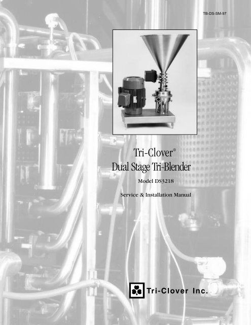
<strong>Tri</strong>-Clover ®<br />
<strong>Dual</strong> <strong>Stage</strong> <strong>Tri</strong>-<strong>Blender</strong><br />
Model DS3218<br />
Service & Installation Manual
CONTENTS<br />
Thank you for purchasing a <strong>Tri</strong>-Clover Product!<br />
This manual contains installation, operation, cleaning and repair instructions, with parts lists, for <strong>Dual</strong><br />
<strong>Stage</strong> <strong>Tri</strong>-<strong>Blender</strong>s manufactured by <strong>Tri</strong>-Clover Inc., Kenosha, Wisconsin. It also provides a<br />
troubleshooting chart to assist in determining blender malfunction.<br />
READ THIS MANUAL carefully to learn how to service the <strong>Tri</strong>-<strong>Blender</strong>. Failure to do so could result<br />
in personal injury or equipment damage.<br />
SAFETY<br />
IMPORTANT SAFETY INFORMATION .......................................................................................... 4<br />
INTRODUCTION<br />
DESCRIPTION................................................................................................................................ 5<br />
BASIC OPERATION ....................................................................................................................... 5<br />
INSTALLATION<br />
INSTALLATION GUIDELINES ........................................................................................................ 6<br />
PIPING HINTS ................................................................................................................................ 7<br />
MAINTENANCE<br />
CLEANING ...................................................................................................................................... 8<br />
DISASSEMBLY ............................................................................................................................... 8<br />
REASSEMBLY .............................................................................................................................. 11<br />
SETTING THE DRIVE COLLAR AND SEAL REPLACEMENT ..................................................... 15<br />
TROUBLESHOOTING<br />
TROUBLESHOOTING GUIDELINES ........................................................................................... 16<br />
PARTS LIST<br />
MODEL DS3218 ............................................................................................................................ 18<br />
EXPLODED VIEW ........................................................................................................................ 19<br />
3
SAFETY<br />
IMPORTANT SAFETY INFORMATION<br />
Safety is very important!<br />
DO NOT attempt to modify any <strong>Tri</strong>-Clover product. To do so could create unsafe conditions and<br />
void all warranties. DO NOT place any <strong>Tri</strong>-Clover product in an application where general<br />
product service ratings are exceeded.<br />
The following DANGER, WARNING, AND CAUTION signs and their meanings are used within these<br />
instructions.<br />
!<br />
DANGER<br />
Indicates an imminently hazardous situation which, if not<br />
avoided, will result in death or serious injury. The word<br />
Danger is used in the most extreme cases.<br />
WARNING<br />
Indicates a potentially hazardous situation which, if not<br />
avoided, may result in minor or moderate injury. May<br />
also be used to alert against an unsafe operating or<br />
maintenance practice.<br />
CAUTION<br />
Indicates a potentially hazardous situation which, if not<br />
avoided, could result in death or serious injury.<br />
Safety labels are placed on every <strong>Tri</strong>-<strong>Blender</strong>. Do not remove any labeling on any <strong>Tri</strong>-Clover product.<br />
Immediately replace any label that is missing.<br />
WARNING<br />
ROTATING SHAFT<br />
DO NOT OPERATE<br />
WITHOUT GUARD IN PLACE<br />
Part Number 38-241<br />
4
INTRODUCTION<br />
DESCRIPTION<br />
The <strong>Dual</strong> <strong>Stage</strong> <strong>Tri</strong>-<strong>Blender</strong> consists of two basic sections, the dry material section and the liquid<br />
material section.<br />
The <strong>Dual</strong> <strong>Stage</strong> <strong>Tri</strong>-<strong>Blender</strong> is mounted on a base plate. It is mounted adjacent to the drive motor<br />
and is driven by belts running between pulleys under the base plate. The manually controlled<br />
Butterfly valve is standard equipment.<br />
On this model, the connection ends, the diffuser and the suction tube, the inlet adapter, the casing,<br />
screens, washer, the impellers and backplate are made of 316 stainless steel. The hopper is made of<br />
304 stainless steel. All of the tubes are fastened with quick couple <strong>Tri</strong>-Clamps for easy care and fast<br />
access. The four legs supporting the <strong>Tri</strong>-<strong>Blender</strong> are adjustable for easy leveling of the blender during<br />
installation.<br />
BASIC OPERATION<br />
The <strong>Tri</strong>-<strong>Blender</strong> basically consists of a centrifugal pump<br />
head and impeller mounted so that the normal suction<br />
port, or inlet, is pointed upward. The inlet piping<br />
consists of a patented tube-within-a-tube arrangement.<br />
This serves to keep the liquid and dry ingredients<br />
separated until they are in the mixing chamber. The<br />
tube-within-a-tube arrangement eliminates prewetting,<br />
one of the major problems of wet-dry mixing.<br />
Our patented (U.S. Patent # 4,850,704) dual stage <strong>Tri</strong>-<br />
<strong>Blender</strong> incorporates the proven design characteristics<br />
of our popular Single <strong>Stage</strong> <strong>Tri</strong>-<strong>Blender</strong>, but takes the<br />
concept a step further for even more efficiency.<br />
The <strong>Dual</strong> <strong>Stage</strong> concept provides for "double blending."<br />
The product passes through the initial liquid/dry<br />
ingredient blending chamber directly below to a<br />
secondary chamber, which effectively acts as a<br />
discharge pump.<br />
Due to its close proximity, the dual (or second) chamber concept actually increases, rather than<br />
decreases vacuum. The vacuum from the suction of the second pumping stage is added to that of<br />
the first stage, greatly improving product addition rates. The "double blend" feature improves end<br />
product consistency, providing a smoother, more uniform blend.<br />
With the <strong>Dual</strong> <strong>Stage</strong>, in applications up to 500 CPS and up to 50 feet (15m) of discharge head, no<br />
discharge pump is required. This is a significant improvement over the Single <strong>Stage</strong> units, which<br />
normally require an auxiliary discharge pump at 25 feet (7.5m) of discharge head and above. On<br />
some applications with higher CPS, a discharge pump may be necessary.<br />
By incorporating the discharge pump function into the blender itself, you can achieve e significantly<br />
higher vacuum rates over a wider range of process conditions. The increased vacuum provides for<br />
fast, consistent product flow rates with no drop-off through your entire production run.<br />
5
INSTALLATION GUIDELINES<br />
UNPACKING EQUIPMENT<br />
INSTALLATION<br />
When unpacking your equipment, inspect all of the contents for damage that may have occurred<br />
during shipping. Report any damage to the carrier.<br />
LOCATION AND INSTALLATION<br />
The <strong>Tri</strong>-<strong>Blender</strong> unit should be located within 3 feet of the liquid source for best performance and in a<br />
position where the supply piping can be short and direct with a minimum number of elbows and<br />
fittings. The liquid to the blender must be supplied by an auxiliary source. It should also be readily<br />
accessible for cleaning and inspection.<br />
The <strong>Tri</strong>-<strong>Blender</strong> unit is ready to install as received from the factory. A minimum space of 32" x 47"<br />
(81cm x 119cm) is required. Install the adjustable legs in the base of the unit and position the blender<br />
in the area it will be used. Turn the adjusting leg with a wrench and individually adjust the legs until<br />
the unit is level.<br />
Attach the supply and discharge piping. Be sure that both the inlet and outlet tubes are correctly<br />
positioned and that supply and discharge piping are properly supported to avoid strain on the blender<br />
casing.<br />
The tube OD of the inlet and outlet connections of the blender casing are:<br />
Liquid Inlet Liquid Outlet Powder Inlet<br />
1½" (38.1mm) 2" (50.8mm) 3" (76.2mm)<br />
IMPORTANT:<br />
If your blender is equipped with the electrically controlled Butterfly valve,<br />
be sure the valve is wired to an auxiliary 110V power source. The axillary<br />
wiring will let the Butterfly operate independently from the blender motor<br />
and will allow the valve to be closed if the drive motor stops running. If<br />
the auxiliary 110V power source also fails, the Butterfly valve is equipped<br />
with a manual override to close (or open) the valve by applying a suitable<br />
size wrench to the flats on the coupling adapter.<br />
6
INSTALLATION<br />
PIPING HINTS<br />
GENERAL<br />
This section provides some hints on piping installation, which will aid in obtaining maximum efficiency<br />
and service from your <strong>Tri</strong>-<strong>Blender</strong>.<br />
Piping should be independently supported at both the inlet and discharge outlet. Care should be<br />
taken that piping is properly aligned and does not put any strain on the <strong>Tri</strong>-<strong>Blender</strong> casing. The piping<br />
should have minimum line restriction.<br />
INLET PIPING<br />
The inlet piping should be short and follow a direct route with a minimum number of elbows and<br />
fittings. Elbows should not be used at the inlet as friction would be greatly increased, resulting in<br />
head loss. Excessive friction losses in the inlet line could cause cavitation in the blender casing,<br />
causing poor performance, noise, vibration, and damage to equipment.<br />
Whenever practical, the diameter of the piping at the inlet should be increased in size. An eccentric<br />
tapered reducer should be used in lieu of a concentric tapered reducer to help direct the flow into the<br />
offset tee to minimize turbulence.<br />
7
MAINTENANCE<br />
CLEANING<br />
C.I.P. CLEANING<br />
The <strong>Dual</strong> <strong>Stage</strong> <strong>Tri</strong>-<strong>Blender</strong> can be cleaned in place. If the <strong>Tri</strong>-<strong>Blender</strong> is to be cleaned, the butterfly<br />
valve must be removed and cleaned separately. Refer to separate valve service manual. In addition,<br />
the dry ingredients inlet adapter tube must be capped off.<br />
DISASSEMBLY<br />
GENERAL<br />
The <strong>Tri</strong>-<strong>Blender</strong> is relatively maintenance free, requiring normal cleaning and inspection to ensure<br />
optimum performance. Inspect all seals for cuts or abrasions and inspect seal faces for nicks and<br />
cracks. Replace worn or damaged parts as necessary.<br />
REPAIR INFORMATION<br />
Repair of the <strong>Tri</strong>-<strong>Blender</strong> is normally accomplished by replacing defective parts. The only moving<br />
parts are the control valve, the impellers, the drive shaft, the seal, the belt, and the motor armature<br />
shaft. It is recommended that all parts of the <strong>Tri</strong>-<strong>Blender</strong> be periodically inspected to prevent<br />
malfunctions caused by worn or broken parts. For repair or replacement of the drive motor, refer to<br />
the motor manufacturer. For repair and service of the Butterfly valve on your blender, refer to B<br />
Series Butterfly Valve Service and Installation Manual (B51SM) available from <strong>Tri</strong>-Clover. Refer to<br />
the parts list for replacement data for the <strong>Tri</strong>-<strong>Blender</strong> parts.<br />
TRI-BLENDER DISASSEMBLY<br />
Remove power before<br />
servicing to prevent<br />
unintended start of the<br />
blender.<br />
WARNING<br />
Relieve pressure and<br />
remove all fluid from blender<br />
prior to disassembly.<br />
1<br />
3<br />
4<br />
5<br />
3<br />
4<br />
1. Remove the clamp (3) securing the hopper (1) to the blender and remove the<br />
hopper and gasket (4).<br />
7<br />
8<br />
2. Remove the clamp (3) securing the control valve (5), and remove the valve and<br />
9<br />
gasket (4). (Hold the valve while loosening the clamp to prevent the valve from<br />
10<br />
falling.)<br />
8<br />
3. Remove the clamp (8) securing the diffuser and suction tube (7), and remove the<br />
diffuser and suction tube and gasket (9).<br />
9<br />
4. Remove the clamp (8) securing the inlet adapter (10), and remove the inlet adapter and gasket (9).<br />
8
MAINTENANCE<br />
5. Remove the clamp (22) securing the upper casing (11a) to the lower<br />
casing (11b). Grasp the upper casing firmly in both hands and pull the<br />
casing straight up and off of the lower casing.<br />
11a<br />
IMPORTANT:<br />
Do not use a tool to pry the casings apart. Any object<br />
inserted between the casing and gasket could cause<br />
damage to the gasket and casing sealing surface,<br />
resulting in leakage after reassembly.<br />
22<br />
13<br />
14<br />
15a<br />
6. Remove and inspect the casing o-ring (16).<br />
12<br />
7. Remove the upper screen (12).<br />
17<br />
8. Using a suitable wrench remove the nut (13) securing the upper impeller<br />
(15a) to the stub shaft. Remove the impeller nut o-ring (14), upper<br />
impeller (15a), and backplate (17).<br />
16<br />
9. Remove the diffuser plate (51) and lower o-ring (16).<br />
51<br />
10. Remove the shaft sleeve (54) and o-rings (54a).<br />
11. Remove the lower impeller (15b), and lower screen (12).<br />
54a<br />
54<br />
54a<br />
12. Remove the o-ring (26) from the lower impeller (15b).<br />
13. Loosen the three casing bolts, and lift the lower casing (11b) off of the<br />
adapter ring.<br />
14. Remove four screws (66) securing the seal gland (67) to the lower casing<br />
(11b). Inspect all parts of the seal for damage or wear and replace as<br />
required. For the DG seal, use caution when handling the casing to avoid<br />
damage to the surfaces around the opening for the carbon seal.<br />
15. Remove the carbon seal (25), o-ring seal (26), cup (27), spring (28) and<br />
drive collar (52) from the stub shaft. To remove the drive collar, loosen<br />
the setscrews (53) and lift the drive collar off of the shaft,<br />
68<br />
12<br />
15b<br />
26<br />
69<br />
16<br />
11b<br />
68<br />
If you need to disassemble the stub shaft and motor, refer to Stub Shaft and<br />
Motor Removal following this section.<br />
66a<br />
66<br />
67<br />
25<br />
27<br />
26<br />
28<br />
52<br />
53<br />
9
MAINTENANCE<br />
STUB SHAFT AND MOTOR REMOVAL<br />
Note: When removing drive components, it is<br />
necessary to tip the entire blender and base<br />
on its side, with the motor end toward the<br />
floor. Remove the hopper, valve, tubing,<br />
casing, impeller, seal guard and seal<br />
components before tipping to make the unit<br />
easier to lift.<br />
1. Loosen the mounting bolts (43) securing the drive<br />
motor (50) to the base (39). (The bolt holes are<br />
elongated to permit belt adjustment.)<br />
2. Slide the motor (50) toward the blender and<br />
remove the drive belts (45).<br />
3. Remove the bolts (44b) securing the blender<br />
pulley (44c). Use the same bolts as a forcing<br />
screw and thread it into the forcing holes, finger<br />
tight.<br />
4. With a suitable wrench, turn the bolt (44b) until<br />
the pulley (44c) releases from the bushing (44a).<br />
Remove the forcing screw and remove the<br />
pulley.<br />
5. Slide tapered bushing (44a) from the shaft (31).<br />
6. Loosen the set screws (53) securing the collar<br />
(30) to the shaft (31) and remove the deflector<br />
collar.<br />
7. Loosen the six capscrews (43) securing the<br />
adapter ring spacers (37). Hold the adapter ring<br />
(23) to prevent it from falling. Remove the<br />
capscrews and remove the adapter and spacers.<br />
8. Set the blender down on its legs (41). Remove<br />
the four capscrews (36) and lockwashers (36a)<br />
securing the bearing housing (34) to the base<br />
(39).<br />
9. Grasp the bearing housing (34) firmly in both<br />
hands and lift it out of the blender base (39).<br />
10. Remove the retaining ring (38) and press the shaft (31) out of the housing (34). Using a suitable<br />
puller, remove the bearing (33) from the shaft and remove the other bearing from the housing.<br />
11. Inspect the shaft (31) sealing surface for nicks or scratches. Inspect all components for cracks<br />
and distortion. Inspect the adjusting legs for worn threads and inspect all o-rings for damage.<br />
12. Replace any worn or damaged components.<br />
IMPORTANT:<br />
The three bearings in the bearing housing are sealed and lifetime lubricated.<br />
If either of the bearings are worn or damaged, make certain they are<br />
replaced with exactly the same type of bearings and replaced as a set.<br />
10
MAINTENANCE<br />
REASSEMBLY<br />
1. Install the o-ring (26) in the deflector collar (30).<br />
2. Install two bearings (33) on the shaft (31) from the bottom until they rests against<br />
the shoulder.<br />
3. Install the shaft into the bearing housing (34).<br />
4. Install the other bearing (33) on the shaft (31) through the bottom of the housing<br />
(34).<br />
5. Install the retaining ring (38) on the bottom of the shaft (31).<br />
6. Install the bearing housing (34) on top of the base (39) and tighten the bolts.<br />
7. Install the deflector (30) on top of the bearing housing (34).<br />
8. Screw the six spacers (37) into the adapter ring (23), and bolt the spacers onto<br />
the baseplate (39).<br />
9. Install the DG insert into the gland ring with gaskets (68).<br />
Note: If you are using a stainless steel replaceable seat, you won't have<br />
an insert and you'll only use one gasket between the lower casing<br />
and the seat.<br />
10. Install the lower casing (11b) over the shaft (31) and onto the adapter ring.<br />
Use the three casing bolts (11c, shown above) to secure the casing to the<br />
adapter ring.<br />
11. Alternately tighten the spacer bolts (37) to center the shaft (31) in the lower casing (11b).<br />
11
MAINTENANCE<br />
12. Tip the base on its side (39), and install the motor (50).<br />
Tighten the bolts enough so that they contact the<br />
bottom of the base. You’ll use the bolts later to adjust<br />
the belt tension.<br />
13. Install the blender pulley key (44d), pulley (44b), and<br />
bushing (44c) and tighten the bolts (44a). Place the<br />
pulley in position using the correct mounting holes for<br />
the bolts securing the pulley.<br />
14. Install the motor pulley key (46d), pulley (46b), and bushing (46c) and tighten the bolts (46a).<br />
Make sure that both pulleys are horizontally aligned. Draw the pulley tight with the mounting<br />
bolts by alternately tightening each bolt a small amount until all three bolts are tight.<br />
15. Place the drive belt (45) on the motor pulley (46b) and the blender pulley (44b). It may be<br />
necessary to move the motor toward the blender to place the belts on the pulleys. Tighten the<br />
belts by moving the drive motor away from the blender housing until there is a deflection of 5 /16"<br />
(7.9 mm) using 5 to 7 pounds of force on the belt. Tighten the motor bolts.<br />
16. Turn the blender upright.<br />
17. Assemble the seal. Refer to Setting the Drive Collar and Seal Replacement section (all motors)<br />
at this point. Then return to Step 17.<br />
18. Slide the lower impeller (15b) with the o-ring onto the shaft (31) and down into the lower casing<br />
(11b).<br />
19. Slide the shaft sleeve (54) with two o-rings (54a) onto the shaft (31).<br />
12
MAINTENANCE<br />
20. Install the upper impeller (15a) onto the shaft (31) with the<br />
impeller nut (13) and o-ring (14).<br />
21. Loosen all spacer bolts (43) to set the clearance between the<br />
lower casing and the lower impeller.<br />
22. Select three alternating adapter ring spacers (37) to adjust for a<br />
.015 to .020 inch clearance between the lower casing and the<br />
lower impeller. Adjust the spacers to obtain a level adjustment.<br />
Tighten the three spacers using the base plate screws (43) to<br />
secure the setting. Recheck the clearance to ensure proper<br />
adjustment.<br />
23. Adjust the three remaining spacers (37) to take up the gap<br />
between the end of the spacer and the base plate. (Also takes up<br />
slack in the threads of the first 3 spacers to prevent casing<br />
movement due to thread clearances.)<br />
24. Tighten the three remaining screws (43) of the spacer to the base plate<br />
connections.<br />
24. Remove the upper impeller (15a).<br />
25. Place the lower screen (12) inside the lower casing (11b) with the pin on the<br />
screen facing upward and lined up with the step in the lower casing.<br />
26. Install the diffuser plate (51) on the lower casing (11b), ensuring that the<br />
pin in the plate fits in the notch in the lower casing. (The pin in the lower<br />
screen must also fit inside the notch on the diffuser plate.)<br />
27. Install the back plate (17).<br />
28. Install the upper impeller (15a) onto the shaft with the impeller nut (13) and o-ring (14).<br />
29. Install the upper screen (12) with the pin down. Rotate the screen counterclockwise until it rests<br />
against one of the tabs on the back plate (17).<br />
13
MAINTENANCE<br />
30. Install the upper casing with o-ring, ensuring that the pins on the upper casing fit into the notches<br />
on the lower casing, and install and tighten the clamp.<br />
31. Install the seal guard (36).<br />
32. Install the inlet adapter (10) on the casing (11),<br />
securing it with a clamp.<br />
IMPORTANT: Be sure to position the adapter (10)<br />
correctly. The adapter inlet should be<br />
opposite the casing outlet (11). See<br />
figure at right.<br />
33. Install the diffuser and suction tube (7) and gasket in<br />
the adapter (10), and secure it with a clamp.<br />
34. Install the butterfly valve (5) and gasket, and secure<br />
it with a clamp (3).<br />
35. Install the hopper (1) and gasket (4) , and secure it<br />
with a clamp (3).<br />
14
MAINTENANCE<br />
SETTING THE DRIVE COLLAR AND SEAL REPLACEMENT<br />
Complete these steps before returning to final reassembly steps in<br />
preceding section.<br />
1. Slide the drive collar and seal assembly toward the seal seat until<br />
the nose of the drive collar pushes the o-ring and carbon seal tight<br />
against the seal seat.<br />
2. Slide the drive collar away from the seal seat 1/32 inch (0.8mm) and<br />
secure the drive collar in this location with the set screws.<br />
3. Remove the impeller screw and the upper impeller.<br />
4. Insert the lower impeller screen with the pin up to align with the hole<br />
in the diffuser.<br />
5. Install the diffuser with an o-ring in the lower casing.<br />
6. Install the backplate onto the diffuser.<br />
7. Insert the upper impeller screen so the pin faces down and when rotated clockwise rests against<br />
one of the 4 tabs of the backplate.<br />
8. Attach the upper impeller to the shaft with the impeller screw and o-ring.<br />
9. Attach the upper casing and o-ring with the large <strong>Tri</strong>-Clamp to the lower casing while aligning the<br />
backplate tabs with the upper casing grooves.<br />
10. Assemble the remaining tubes and seals securing each section with the proper size clamps.<br />
11. With the blender assembled, and casing clamp tightened, if the drive collar is properly positioned,<br />
and the seal components are properly installed, the blender shaft should rotate freely by hand. If<br />
excessive effort is required to rotate the shaft, check to be sure that all components are properly<br />
installed and the drive collar is properly positioned.<br />
12. Assemble seal guard and tighten nut.<br />
After above setting instructions have been followed, return to the Reassembly section for final steps.<br />
15
TROUBLESHOOTING<br />
TROUBLESHOOTING GUIDELINES<br />
<strong>Tri</strong>-<strong>Blender</strong>s are relatively maintenance free with the exception of sanitizing and inspection. Like any<br />
piece of machinery, however, occasional problems can arise. This section provides a means of<br />
determining and correcting most of your <strong>Tri</strong>-<strong>Blender</strong> problems. The motor manufacturer should be<br />
contacted for specific repair instructions on the motor.<br />
The chart below has been prepared on the basis that the <strong>Tri</strong>-<strong>Blender</strong>, as installed, is properly suited to<br />
its application. Should problems arise where the remedies listed below chart do not cure the situation,<br />
impeller cavitation may be the problem. Symptoms of cavitation, such as noisy operation, insufficient<br />
discharge and vibration, can result when the auxiliary pump or suction tube are not properly applied. If<br />
these conditions are present, check the system and reevaluate the application. If assistance is<br />
required, contact <strong>Tri</strong>-Clover.<br />
PROBLEM<br />
1. No suction.<br />
2. Insufficient<br />
discharge.<br />
PROBABLE CAUSE<br />
a. Wrong supply pump or need of<br />
discharge pump.<br />
b. Leak on the suction side of the<br />
supply pump or blender.<br />
c. Carbon seal is worn.<br />
d. Wrong direction of rotation.<br />
e. Inlet port on wrong side.<br />
f. Splashing in the suction throat<br />
of the <strong>Tri</strong>-<strong>Blender</strong>.<br />
g. High viscosity.<br />
h. High temperature.<br />
a. High viscosity with screen in<br />
casing.<br />
b. No liquids.<br />
c. Product too viscous or<br />
discharge head too great.<br />
REMEDY<br />
a. Verify that pumps are sized correctly to<br />
suit application. Contact <strong>Tri</strong>-Clover if<br />
you require assistance.<br />
b. Tighten all clamps, fittings - replace worn<br />
out gaskets.<br />
c. Replace carbon seal on blender and/or<br />
supply pump.<br />
d. Reverse a three phase motor by<br />
switching any of the three power leads at<br />
the motor or controller on blender or<br />
supply pump.<br />
e. Remove inlet adapter housing and<br />
relocate so it is correctly positioned as<br />
shown on the exploded view pages.<br />
f. High Flow - oversized supply pump; see<br />
1a above; see 1e above.<br />
g. See 3b.<br />
h. Reduce temperature below 140°F<br />
(60°C).<br />
a. Remove screen.<br />
b. Check supply pump.<br />
c. Add discharge pump.<br />
16
TROUBLESHOOTING<br />
PROBLEM<br />
3. Excessive<br />
power<br />
consumption.<br />
4. <strong>Tri</strong>-<strong>Blender</strong> is<br />
noisy.<br />
5. Excessive<br />
vibration.<br />
6. <strong>Tri</strong>-<strong>Blender</strong><br />
leaks.<br />
PROBABLE CAUSE<br />
a. High viscosity with screen in<br />
head.<br />
a. Magnetic hum in motor.<br />
b. Motor bearings are worn.<br />
c. <strong>Tri</strong>-<strong>Blender</strong> bearings are worn.<br />
d. Foreign matter is rotating with<br />
impeller.<br />
a. <strong>Blender</strong> is not leveled properly.<br />
b. Impeller is damaged.<br />
c. Foreign matter in casing.<br />
a. Seal failure.<br />
b. Casing gasket worn or<br />
damaged.<br />
REMEDY<br />
a. Remove screen.<br />
b. Install discharge pump on discharge end<br />
of the <strong>Tri</strong>-<strong>Blender</strong>.<br />
a. Consult motor manufacturer.<br />
b. Consult motor manufacturer.<br />
c. Replace bearings.<br />
d. Remove casing and remove foreign<br />
matter - inspect for damage.<br />
Check supply flow to blender.<br />
a. Level blender.<br />
b. Replace impeller.<br />
c. Remove casing and remove foreign<br />
matter - inspect for damage.<br />
a. Replace seal.<br />
b. Replace gasket.<br />
17
PARTS LIST<br />
MODEL DS3218<br />
All orders for repair parts must contain the following data.<br />
1. Complete model number (located on nameplate).<br />
2. <strong>Tri</strong>-<strong>Blender</strong> serial number (located on nameplate).<br />
3. Description and part key number from the parts list.<br />
The exploded views and accompanying parts list facilitate ordering repair parts from the factory. All<br />
parts of the <strong>Tri</strong>-<strong>Blender</strong> are exploded and keyed to the parts list.<br />
Key<br />
No. Description Part Number Qty<br />
1 40° hopper D3218-55-40-01 1<br />
2 60° hopper D3218-55-60-01 1<br />
3 Clamp 13MHHM-2-S 2<br />
4 Gasket 40MP-U-2 2<br />
5 Manual Butterfly Valve B51A-4-E-S 1<br />
7 Difuser & Suction Tube F3218-05-316 1<br />
8 Clamp 13MHHM-4-S 2<br />
9 Gasket 40MP-U-4 2<br />
10 Inlet Adapter F3218-217-316 1<br />
11a Upper Casing DS3218-1B-01-316L 1<br />
11b Lower Casing DS3218-1A-316L 1<br />
12 Impeller Screen DS3218-215-316 2<br />
13 Screw, upper impeller DS3218-26-316L 1<br />
14 0-Ring, upper impeller 17-15-U 1<br />
15a Upper Impeller DS3218-2B-02-316 1<br />
15b Lower Impeller DS3218-2A-02-316 1<br />
16 O-Ring, casing 17-327-U 2<br />
17 Backplate DS3218-11-316 1<br />
22 Clamp, Casing DS3218-75-S 1<br />
23 Adapter Ring DS3218-71-1-S 1<br />
25 Carbon Seal 328E-80-1A-Mat'l 1<br />
26 O-Ring S328-80-2-U 3<br />
27 Cup 328D-80-3P 1<br />
28 Spring 328D-80-4 1<br />
30 Deflector F3218-40E-S 1<br />
31 Drive Shaft DS3218-06-316L 1<br />
33 Bearings D3218-18 3<br />
34 Bearing Housing F4329-99-S 1<br />
Key<br />
No. Description Part Number Qty<br />
35 Seal Gaurd F3218D-131-S 1<br />
36 Screw, Bearing Housing SC1510H-SS 5<br />
36a Lockwasher, Bearing<br />
LWA1500-SS<br />
Housing<br />
5<br />
37 Spacer DS3218-71A-316L 6<br />
38 Retaining Ring DS3218-177 1<br />
39 Base Plate DS3218-23-S 1<br />
40 O-Ring, Adjustable Leg 01-1154-13-34-U 4<br />
41 Adjustable Leg R3-1-23-03-S 4<br />
42 Washer, Spacer & Motor LWA1700-SS 10<br />
43 Screw, Spacer & Motor SC1712H-SS 10<br />
44 <strong>Blender</strong> Pulley 50 Cycle DS3218-106-5-3V5.0x1.500 1<br />
44 <strong>Blender</strong> Pulley 60 Cycle DS3218-106-5-3V6.0x1500 1<br />
44d <strong>Blender</strong> Pulley Key D3218-46 1<br />
45 "V" Belt D3218-3VX600 5<br />
46 Motor Pulley 50 Cycle DS3218-108-5-3V8.0x1.875 1<br />
46 Motor Pulley 60 Cycle DS3218-108-5-3V8.0x1.875 1<br />
49 Washer, Motor WA1700-SS 4<br />
51 Diffuser Plate DS3218-5-316L 1<br />
52 Drive Collar SP328D-23P-S 1<br />
53 Setscrew SC1105A-SS 1<br />
54 Shaft Sleeve DS3218-14-316L 4<br />
54a O-Ring, Shaft Sleeve 17-51-U 1<br />
66 Bolt, Gland Ring SC1310H-SS 2<br />
66a Lockwasher, Gland Ring LWA1300-SS 4<br />
67 Gland Ring (DG Seal) SP328G-17-316L 4<br />
67a Stainless Steel Seat DS3218-17-316L 1<br />
68 PTFE Gasket SP328G-80-1-2-G 2<br />
69 Seal Seat SP328G-80-1-1-Mat'l 1<br />
18
EXPLODED VIEW<br />
19
<strong>Tri</strong>-Clover<br />
manufactures<br />
a complete line of<br />
TRI-WELD ® fittings<br />
TRI-CLAMP ® fittings<br />
BEVEL SEAT fittings<br />
POSITIVE PUMPS<br />
CENTRIFUGAL PUMPS<br />
AUTOMATIC Air Actuated VALVES<br />
STAINLESS STEEL TUBING<br />
AUTOMATED FLOW CONTROL SYSTEMS<br />
Terms, Warranty Provisions, Notice of Claims and Limitation of Liability<br />
Prices and all terms and conditions of sale are established in<br />
current price sheets and are subject to change without notice. All<br />
orders are subject to acceptance by <strong>Tri</strong>-Clover Inc. at its Kenosha,<br />
Wisconsin or Distribution Center* offices only. No assignment of<br />
the purchaser’s rights may be made without consent of <strong>Tri</strong>-Clover<br />
Inc.<br />
Each <strong>Tri</strong>-Clover item is warranted to be free from manufacturing<br />
defects for a period of one (1) year from the date of shipment,<br />
providing it has been used as recommended and in accordance with<br />
recognized piping practice, and providing it has not been worn out<br />
due to severe service, such as encountered under extremely corrosive<br />
or abrasive conditions.<br />
This warranty is expressly in lieu of any other warranties,<br />
express or implied, including but not limited to, any implied<br />
warranty of merchantability or fitness for a particular purpose.<br />
All claims must be in writing and must be mailed or delivered<br />
by purchaser within thirty (30) days after purchaser learns of the<br />
facts upon which such claim is based. Any claim not made in writing<br />
and within the time period specified above shall be deemed waived.<br />
Purchaser’s sole and exclusive remedy and <strong>Tri</strong>-Clover<br />
Inc.’s maximum liability for claims arising hereunder or for<br />
negligence for any and all losses and damages resulting from<br />
any cause shall be either the repair or replacement of defective<br />
items or, at <strong>Tri</strong>-Clover Inc.’s option, the refund of the purchase<br />
price for such items. In no event, including in the case of a<br />
claim for negligence, shall <strong>Tri</strong>-Clover be liable for incidental or<br />
consequential damages including loss of profits.<br />
No person, including any representative, employee or agent of<br />
<strong>Tri</strong>-Clover, is authorized to assume on behalf of <strong>Tri</strong>-Clover Inc., any<br />
liability or responsibility in addition to or different from that described<br />
in this provision. Any and all representations, promises, warranties<br />
or statements that are in addition to or different from the terms of this<br />
provision are of no force or effect.<br />
*Distribution Centers in Union City, California and St. Charles,<br />
Missouri.<br />
2.5M<br />
TB-DS-SM-97<br />
Printed in Nov 1997