SUMPC Alsatom Diathermy Unit
SUMPC Alsatom Diathermy Unit
SUMPC Alsatom Diathermy Unit

Create successful ePaper yourself
Turn your PDF publications into a flip-book with our unique Google optimized e-Paper software.
INSTRUCTION MANUAL<br />
ALSATOM SU 50-MPC, SU 100-MPC, SU 140-MPC, SU 140/D-MPC<br />
This unit is manufactured by ALSA APPARECCHI MEDICALI S.R.L., Via C. Bonazzi 16, 40013 Castel Maggiore (BO), Italy, that guarantees its safety,<br />
reliability and performances only if installation, recalibrations and repairs are carried out by personnel authorized by ALSA and if the unit is used in<br />
compliance with the given instructions in an area that meets all the applicable IEC or CEI requirements. The manufacturer is at disposal to supply, if<br />
requested, the electric diagrams and any further information.<br />
In accordance with the ALSA procedures for the after-sale control of the production, the users are pleased to inform the Manufacturer about every,<br />
even little, problem of this unit.<br />
INTRODUCTION<br />
In a biological tissue crossed by an electric current are shown the following effects:<br />
- thermal, faradic, electrolytic.<br />
By using HF electric current the last 2 undisired and useless effects are eliminated and it is utilized above all the thermal effect. In fact<br />
when an electric current having such characteristics flows, from the active electrode to the neutral one, with sufficient density the cellular<br />
liquid of the tissues warms it and produces the following effects:<br />
1) heating is so quick that the pressure of the vapour created in the cells breaks their membranes (cutting);<br />
2) heating is lower, so the liquid slowly evaporates allowing the coagulation of the coagulable components of the tissues (coagulation or<br />
haemostasis);<br />
3) the effect is a middle way between the two above-described ones (cut with coagulation).<br />
The ESU is “ HF device” that may destroy the cells of biological tissues and therefore it should be used by expert staffs in electrosurgery<br />
and respecting strictly all the given instructions.<br />
The ALSATOM SU-MPC series can be used for every kind of monopolar/bipolar cut and coagulation/microcoagulation in:<br />
GYNAECOLOGY, DERMATOLOGY, PLASTIC SURGERY, DENTAL AND MAXILLO-FACIAL SURGERY, ANGIOLOGY,<br />
GENERAL SURGERY, ORL, GASTROENTEROLOGY, VETERINARY.<br />
In particular, the functions are as follows:<br />
- CUT: Monopolar pure cut without coagulation<br />
- BLEND: Monopolar cut with coagulation<br />
- COAG: Monopolar coagulation (high voltage-fulguration)<br />
- COAG MICRO Monopolar coagulation (low voltage-soft)<br />
- BIPOLAR Bipolar coagulation.<br />
Before using these units, control their performance (for example on a piece of meat) without relying completely on the previous<br />
experiences with other devices. Always start with very low powers, then gradually raise up until obtain the desired surgical effect.<br />
GENERAL PRECAUTIONS – It is dangerous to ignore the following warnings:<br />
1- It is dangerous to use the device if the operating theatre doesnot meet CEI/IEC electrical requirements.<br />
- Do not use “extension leads” for the power supply cable. Contact the technical department for the compatibility of other<br />
equipment eventually in use.<br />
2- It is extremely dangerous to use accessories or instruments which are not perfectly compliant with all the applicable technical or<br />
legislative Rules, and which are not suitable for the working voltages of the device (approx. 2800Vpp “1500Vp” for the<br />
monopolar currents with crest factors equal or higher than 2; 1200 Vpp “600Vp” for the monopolar currents with crest factors<br />
lower than 2; approx. 400Vpp “220Vp for the bipolar currents with crest factors equal or lower than 2). Moreover, the accessories<br />
and instruments must not be old nor worn. Check always their status before the use, notably if for endoscopy. Bear in mind that:<br />
- All the old/worn active electrodes, accessories and cables do not work properly, and do not guarantee the perfect insulation. In<br />
addition, their unstable functioning can lead the operator to increase the output powers at dangerous levels;<br />
- In the user manual, for each current, the maximum output voltage “Vpp” and its variation (see the curves) according to the output<br />
power adjustment are specified. This allows the operators to choose the maximum output power that must not be overcome, in<br />
order to not exceed the rated HF insulation voltage, which is possible for each accessory;<br />
- The standard monopolar active electrodes for normal surgery have a stem with Ø 2.3mm (so, the standard electrode-holder<br />
handles are suitable for the electrodes having stems with this diameter).<br />
3- The interference of HF units may harm the other electromedical equipments in use.<br />
4- Contact cardiological department when using a HF unit on patient with pace-maker (the device can interfere its efficiency causing<br />
fibrillations and ect. or damage their electrodes).<br />
5- Always take metal objects off the patients (ring, chain and etc.). Do not use a HF unit in the presence of flammable anaesthetic<br />
gases (i.e. oxygen, nitrogen protoxide and etc.) especially if operating in cavities (chest, abdomen, trachea, head, etc.)<br />
6- Do not use flammable cleaning substances, disinfectants or solvents, or at least carefully evaporate them before operation.<br />
Always remove the remaining substances from hollow parts of the body or cavities (umbilicus, vagina, etc.) and from underneath.<br />
While using the device, a spark may cause the endogenous gas (intestine) explosion or set fire to oxygen saturated material<br />
(cotton, gauze, etc.).<br />
7- Prevent the patient from touching any metal parts connected to earth or electricity conductors (table, supports, etc.) and isolate<br />
strongly secreting parts of the body and skin-to-skin contacts by using dry covers (i.e. between arm and body).<br />
8- Position monitoring electrodes (not specifically shielded) as far as possible from the electrodes of the HF units. If possible<br />
avoiding the needle type or small-sized ones.<br />
9- Use and position the neutral electrode as follows:<br />
- Choose an area of the body as near as possible to the area to be operated (the ideal is a flabby part without hairs where there<br />
are no protruding bones or uneven surfaces). Clean it, shave it and massage it to favour circulation.<br />
MN SU-MPC ING March 2008 Page 1 of 9
- Firmly fix the electrode without placing anything in-between, ensuring the best contact possible over the entire surface but<br />
without pressing too hard to avoid creating ischemic areas (maybe use conductive gels, etc.) and always make sure that the<br />
contact is constant, especially if the patient is moved or when liquids are poured.<br />
10- The position of the neutral electrode with regard to the operating area creates an HF current route and remember that any metal<br />
objects (prostheses, catherters, etc.) in that area may cause current concentrations that heat or even burn the adjacent tissue.<br />
11- Position the cables of the electrodes so that they do not touch the patient or other wires.<br />
12- Always use the lowest power possible to the surgical need.<br />
The insufficient performance of the equipment may depend on: wrong positioning or faulty contact of the neutral plate, faulty<br />
connection of electrodes, poor conditions of the active electrode and therefore check these factors before increasing the power.<br />
13- Use the bipolar technique for operating on small portions of tissues or in cavities.<br />
14- When the unit is in use, don’t touch with the active electrode the neutral one (short circuit) and try to avoid the activation when<br />
the active electrode doesn’t touch the tissues – it might damage the unit or reduce its life. Please respect the suggested working<br />
times.<br />
15- Contact the Technical Department for the use of “disposable” electrodes.<br />
16- In case lack of supply mains, turn off the unit (setting output power at ZERO).<br />
17- Pay attention that the fault of the HF unit might cause an unexpected power increase.<br />
POSITIONING OF THE PATIENT AND USING OF NEUTRAL PLATE<br />
By using monopolar technique, it is very important that all the currents reaching the patient must return to the unit via the neutral plate,<br />
otherwise two serious consequences will be encountered:<br />
1. HF current discharges from the patient through an insufficient part of the same neutral plate or via casual contacts of conductive<br />
objects (operating table, wet clothes, supports and etc.), since these contact surfaces can be insufficient, the current crossing them may<br />
cause some burns.<br />
2. Output power may lower considerably<br />
Therefore use and position the neutral plate respecting the par. “General Precautions”.<br />
Remember that, using a HF unit, it may occur phenomena generally named as “shocks” but these phenomena are normally only<br />
stimulations or radiofrequency discharges depending on the same contact between the operator and the patient. In case they<br />
happen it is advisable that the operator avoids the direct contacts with patient (e.g. use surgical gloves as insulating) and, if<br />
possible, has not ground contact (use clogs, insulating chair, and so on…).<br />
SAFETY CIRCUIT OF THE NEUTRAL PLATE<br />
The unit is equipped with the neutral plate connection control circuit that, when the monopolar performance is selected, blocks the output<br />
power (if the neutral electrode is not connected or the relevant cable is broken) with specific alarm (intermittente sound and red light).<br />
This circuit doesn’t occur when the bipolar coagulation is selected but the red light signal is put on.<br />
WAY TO USE AND PRATICAL PROPOSALS<br />
1. Check the power supply mains (it must correspond with the technical data at the back) and connect the device with main switch (1)<br />
position OFF. Connect the pedal switch tubing (socket 3 at the back) crew tightly the connector without pushing on the pedal (the<br />
mod. 140/D is provided with 2 sockets for the double pedal switch and the connection must be performed as follows: yellow<br />
tubing of the double pedal to the left socket with yellow area, blue tubing of the double pedal to the right socket with blue area ). The<br />
pedal is pneumatic type, without electric current, waterproof and explosion proof.<br />
2. Connect the electrodes as follows:<br />
- neutral electrode (socket 6) and active electrode (socket 7)<br />
Modd. 140 and 140/D: hand-switch pencil (7A) pedal-switch pencil (7B). For endoscope cables and etc. use only socket 7B,<br />
if neccessary ask for specific adapters.<br />
- Bipolar electrode (socket 8 without any polarity of the pins)<br />
The ALSA standard bipolar cable has this following connector:<br />
3. Put on the unit by the switch 1<br />
4. Set up the initial power as follows:<br />
- modd. SU 100 and SU 50 by control 5,<br />
- modd. SU 140 and SU 140/D by control 5A (pure cut or blend cut), and control 5B (coagulation, micro-coagulation, bipolar<br />
coagulation).<br />
5. Select the performance by selector 4 and activate the output as follows:<br />
modd. SU 100 and SU 50 ............ (selector 4 - position: cut, blend, coag., micro coag., bip. coag.) activation by single pedal switch;<br />
mod. SU 140/D ............................ (selector 4 – position: cut/ coag., cut/micro coag., blend/coag.,) activation by hand switch pencil<br />
or double pedal switch (yellow for cut, blue for coagulation);<br />
(selector 4 – position: bip. coag.) activation by only the pedal switch (blue);<br />
mod. SU 140 ................................ (selector 4 – position: cut/coag.) activation by hand switch pencil;<br />
(selector 4 – position: cut, blend/coag., micro coag., bip. coag.) activation by single pedal switch.<br />
The activation is indicated: cut/blend by yellow light and low acoustic signal, coag./micro coag. by blue light and high acoustic signal,<br />
bipolar coag. by blue light and louder acoustic signal.<br />
To optimize the running of the units follow the following general indications:<br />
1. Do not activate the unit before touching the tissues by the active electrode (otherwise they will creat electric arcs able to produce<br />
eschar on tissue and preventing them from good cicatrization).<br />
2. Keep the active electrode as clean as possible. The patina insulating on an electrode doesn’t permit a good contact with the tissues,<br />
thus it lowers the output power and causes sparks or superficial carbonizations.<br />
MN SU-MPC ING March 2008 Page 2 of 9
3. Using the pure cut (especially with the loop/conization electrodes) if the first effect is not satisfactory (with a slight sticking of the<br />
tissue on the electrode), to have the best result increase the power of 10÷15 W each time.<br />
Pure cut<br />
(for biopsy, laparoscopy, cut or skin incision, uterine conization in gynaecology etc., in general for any<br />
case needing cut without coagulating effect).<br />
1. Use small size electrodes, such as for ex.:<br />
• “thin needle electrode” (from 3÷4 W onwards)<br />
• SAD, SAD/1, SAD/2, SAD/3 “extra-fine needle electrodes” not insulated with diam. from 0.10 to 0.40 mm (from 3÷4 W<br />
onwards)<br />
• “fine loop electrodes” of different measures and shapes (from 8W onwards).<br />
• “long type electrodes” and “LLETZ type electrodes for gynaecology” (from 10W onwards)<br />
2. Select “CUT” current<br />
Cut coagulating<br />
(for laparoscopy, polypectomies or papillotomies in endoscopy, fistulas, haemorrhoids and ect. In<br />
general for any case needing cut combined with an effective coagulating effect).<br />
1. Use the electrodes already mentioned for pure cut or, if possible, the ones with larger section, such as for ex.: knife and thick needle<br />
electrode (from 3÷4 W onwards)<br />
2. Select “BLEND” current and slow a little the sliding of the electrode on the tissue . If coagulating effect is not enough, use even<br />
“COAG.” current.<br />
Micro coagulation<br />
1. Use extra fine needles: AID “insulated needle” (the best for depilation), all the above mentioned “SAD” long type, not insulated<br />
needles for depilation, telangiectasia, spider naevi, pointformed red-ruby angiomas and ect.<br />
2. Use ball electrodes to obtain deep effect avoiding as much as possible a surperficial sparking.<br />
3. Select “COAG MICRO” current (from 0.5 Watt onwards)<br />
Coagulation<br />
1. Use ball electrodes, surgical forceps for coagulation with effective deep effect and good surperficial effect (fulguration).<br />
2. Use small ball, needle, loop or for polipectomy electrodes, etc. to obtain strong superficial effect and limited deep effect.<br />
3. Select “COAG” current (from 2-3 W onwards).<br />
Bipolar coagulation<br />
1. Use bipolar forceps or bipolar electrodes (also for laparoscopy or endoscopy, eventually supplied by the other manufacturers).<br />
2. Select “BIP” current (from 2-3 Watt onwards)<br />
3. Please remind that, to reduce the “sticking phenomena” of the tissue on the tips of the bipolar forceps during the operation, it is very<br />
useful to clam them as little as possible, reduce at maximum the time of activation and moisten them by physicological solution (or<br />
plunged inside a cup or on an imbibed gauze).<br />
AUTOTEST<br />
The running of the unit is completely controlled by microcontroller both during the working and when switching on (starting autotest<br />
which, if regular, ends with short acoustic signal). If any failure the system get blocked the output giving specific error codes (acoustic<br />
signals).<br />
TYPE OF FAILURE<br />
NO. OF<br />
ACOUSTIC<br />
SIGNAL<br />
1. memory RAM 1<br />
SOLUTION<br />
Turn off and re-switch on the unit (if the problem<br />
continues, contact the technical assistance)<br />
2. CRC control software 2 “<br />
3. variables of the system 3 “<br />
4. supply voltage of microcontroller 4 “<br />
5. activation circuits 5 “<br />
6. output power higher than the selected value 6 “<br />
7. incorrect use of the selector 4 7 Check the position of the selector<br />
8. got broken control 5 8 As specified for Fault 1<br />
9. continuous activation for more than 20s 9 Deactivate and reactivate immediately<br />
10. R.F. modulation signal 10 As specified for Fault 1<br />
11. monitoring of the output current 11 “<br />
12. monitoring of R.F. supply 12 “<br />
13. watchdog timer 13 “<br />
14. intervention of neutral plate safety circuit<br />
15. usage error (eg. Activation of cut function if<br />
selecting BIP or activation of 2 switches<br />
comtemporally)<br />
intermittent<br />
(grave)<br />
Intermittent<br />
(acute)<br />
Check the connection of the plug and the cable (bend<br />
and pull it, especially near the plug and the electrode).<br />
If the problem continues, contact the technical<br />
assistance)<br />
Eliminate the cause<br />
Furthermore the following cases may occur:<br />
1. the unit is ON (autotest OK), but when you press the pedal switch, it does not work (without acoustic or light signals) or works<br />
irregularly.<br />
a) check if the pedal is well connected;<br />
b) check if the pedal is broken by activating the unit pushing the central hole of the relevant socket with a round<br />
point. If the unit works regularly it is probably a problem of pedal.<br />
2. the unit is ON (autotest OK), all the running is OK, but there is not output power or it is lower than the normal value.<br />
a) check the good contact of the neutral plate (if the contact is bad or absent there is no power). Remember that the<br />
hair of animals is insulating.<br />
MN SU-MPC ING March 2008 Page 3 of 9
) check if the active electrodes are damaged, if the contact with the pencil is good, if the pencil cable is broken<br />
(pull and bend it, especially near the plug and the handle).<br />
If all the above mentioned interventions do not resolve, please contact the Technical Assitance.<br />
TECHNICAL FEATURES<br />
• Electronic generator in compliance with the Safety Standards IEC 601-2-2 3^ed.<br />
• Monopolar and Bipolar working frequency: 475 kHz<br />
• Classification IEC: I type CF – Classification EC MDD: IIB<br />
• Output circuit: “floating out” protected against the use of the defribrillator<br />
• Mains and Absorption: see rating on the back of the unit<br />
• Mains Fuses: see rating on the back of the unit<br />
• Neutral plate safety circuit with acoustic signal (strong, intermittent) and luminous signal (red)<br />
• Output power : setting by rotary switches<br />
• Running control: by microcontroller with autotest, output error control, error codes<br />
• Protection against liquids: common, not-protected casing<br />
• Cooling by convection without ventilator<br />
• Activation: discontinuous, 10s ON/30s OFF<br />
• Dimensions and weight:<br />
cm (LxDxH) 23x24x10 – Kg 4.75 (modd. SU 140-MPC and SU 140/D-MPC)<br />
cm (LxDxH) 21x24x10 – Kg 4.50 (modd. SU 50-MPC and SU 100/D-MPC)<br />
Conformity EMC/Directive 89/336/CEE: Category A<br />
Suggested distances to keep from not vital devices<br />
Source of the Current RF Typical Power (W) Distance (m)<br />
Microcellular telephones CT1,CT2,CT3 0.01 0.4<br />
Mobile telephones DECT, Wireless devices (modems, LANs) 0.25 2<br />
Mobile telephones (USA) 0.6 3<br />
Hand mobile telephones (GSM, NMT, Europe)<br />
(DECS 1800)<br />
2<br />
8<br />
6<br />
11<br />
Walkie-talkie (police, firemen , protection, maintenance) 5 9<br />
Bag mobile telephones 16 16<br />
Mobile radio (police, firemen, protection) 100 40<br />
For broadcasting stations which use frequencies less than 800MHz, the distance can be established by using the equation: A: d = 4√P<br />
For broadcasting stations which use frequencies between 800MHz and 2.5GHz, the distance can be established by using the equation:<br />
B : d =2.3√P<br />
P = Nominal power of the transmitter in watt (W), established by the manufacturer.<br />
Output power, Vpp-open circuit, Crest factors (SU 100-MPC, SU 140-MPC, SU 140/D-MPC)<br />
Cut: 140 WRMS at 500 Ohm (Vpp 1200, cf 1.7)<br />
Blend: 120 WRMS at 500 Ohm (Vpp 1450, cf 2.8)<br />
Coag: 120 WRMS at 500 Ohm (Vpp 2770, cf 6.9)<br />
Coag Micro: 60 WRMS at 200 Ohm (Vpp 1420, cf 2.8)<br />
Bipolar: 100 WRMS at 100 Ohm (Vpp 400, cf 1.4)<br />
Output power, Vpp-open circuit, Crest factors (SU 50-MPC)<br />
Cut: 80 WRMS at 500 Ohm (Vpp 1000, cf 1.7)<br />
Blend: 80 WRMS at 500 Ohm (Vpp 1420, cf 2.8)<br />
Coag: 80 WRMS at 500 Ohm (Vpp 1950, cf 6.9)<br />
Coag Micro: 60 WRMS at 200 Ohm (Vpp 1420, cf 2.8)<br />
Bipolar: 60 WRMS at 100 Ohm (Vpp 400, cf 1.4)<br />
ATMOSPHERIC CONDITIONS<br />
usage<br />
transport and storage<br />
Temperature (°C) +10 ÷ +40 Temperature (°C) -40 ÷ +70<br />
Humidity 30% ÷ 75% Humidity 10% ÷ 95%<br />
Pressure (hPA) 700 ÷ 1060 Pressure (hPA) 500 ÷ 1060<br />
CLEANING, STERILIZATION, MAINTENANCE, DISPOSAL<br />
1. Clean the unit by neutral soap solution (pay attention: any liquid doesn’t go inside) and wipe it, keep in a dry and not-dusty place<br />
and ensure that is not poured any liquid on it.<br />
2. The unit must be periodically checked (at least once per year) by qualified staff, better by the Manufacturer. Always control the<br />
accessories, if they are not in perfect condition they can be dangerous (eg. Broken cables, dirty electrodes, pins clamped by jury<br />
means and etc.)<br />
3. Waste of the unit must respect every specific national rules.<br />
4. Attention, at the moment of the sale the accessories are not sterile. All the monopolar and bipolar accessories are sterilizable<br />
by autoclave (121°C) or by cold solution (ex. Cydex), the neutral plates by cold solutions only. Sterilize them as indicated in<br />
the instruction of every single package.<br />
STANDARD ACCESSORIES<br />
MPE/E<br />
- Sterilizable pencil with connection cable.(Rated voltage = 4000 Vp)<br />
SEL/VI<br />
- Set of 6 electrodes. (Rated voltage = 4000 Vp)<br />
EIP/9<br />
- Neutral plate with connection cable.<br />
FFE<br />
- Fixing rubber belt for neutral electrode.<br />
D-STOP/P<br />
- Double pneumatic pedal switch (mod. SU 140/D-MPC)<br />
STOP/PN<br />
- Pneumatic pedal switch (modd. SU 50-MPC, SU 100-MPC, SU 140-MPC).<br />
MN SU-MPC ING March 2008 Page 4 of 9
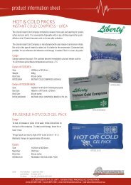
CONTROLS AND SYMBOLS<br />
11<br />
10<br />
9<br />
11<br />
10 9<br />
ALSATOM SU 140/D<br />
ALSATOM SU 140<br />
4<br />
4<br />
5<br />
A<br />
5<br />
B<br />
6<br />
7A<br />
7B<br />
5A<br />
5B<br />
6<br />
7A 7B<br />
11<br />
10<br />
9<br />
11 10 9<br />
ALSATOM SU 100 ALSATOM SU 50<br />
4<br />
8<br />
4<br />
8<br />
5<br />
7<br />
6<br />
5 7 6<br />
At the back<br />
1- Main switch …………. symbol: (switching on) (switching off)<br />
2- Power entry module with double fuse-holder<br />
3- Connection pedal switch ………symbol<br />
only 140/D model:<br />
A = cut (yellow signal)<br />
B = coagulation (blue signal)<br />
In the front<br />
4 Function selector<br />
5 Output power setting (modd. 140 and 140/D:A = pure cut and blend cut; B= coagulation, micro coagulation, bipolar coagulation)<br />
6 Neutral plate socket ................................. symbol:<br />
7 Active electrode socket (modd. 140 and 140/D: A= hand switch handle ...... symbol:<br />
( “ “ B= pedal switch handle ..... symbol:<br />
(modd. 100 and 50 ..................................................... symbol:<br />
8 Bipolar electrode socket ................................................................................... symbol:<br />
9 Output activation/coagulation: (blue light) with display (only modd. 140 and 140/D) ....................... symbol:<br />
10 Output activation/cut: (yellow light) with display (only modd. 140 and 140/D) ................................. symbol:<br />
11 Neutral plate safety circuit (red light) .............................................................. symbol:<br />
Be careful: read the annexed documentation: .......................................................... symbol:<br />
Apparatus of Class I - Type CF – protected against the effect of the defibrillator ... symbol:<br />
Alternating current ................................................................................................... symbol:<br />
MN SU-MPC ING March 2008 Page 5 of 9
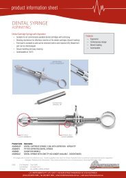
POWER OUTPUT DIAGRAMS (± 20% ) – Modd. SU 100-MPC, 140-MPC, 140/D-MPC (NOTE: in model SU 140-MPC, BLEND<br />
diagram corresponds to BLEND/COAG position of the mode selector)<br />
W RMS<br />
140<br />
130<br />
120<br />
110<br />
100<br />
TAGLIO PURO<br />
MONOPOLARE<br />
90<br />
80<br />
70<br />
MONOPOLAR PURE CUT<br />
SECTION PURE<br />
MONOPOLAIRE<br />
60<br />
50<br />
40<br />
30<br />
20<br />
10<br />
W RMS<br />
130<br />
TAGLIO BLEND<br />
MONOPOLARE<br />
MONOPOLAR BLEND CUT<br />
SECTION AVEC<br />
COAGULATION<br />
MONOPOLAIRE<br />
W RMS<br />
140<br />
COAGULAZIONE<br />
MONOPOLARE<br />
MONOPOLAR<br />
COAGULATION<br />
COAGULATION<br />
MONOPOLAIRE<br />
W RMS<br />
(@ 500 Ω)<br />
Ω<br />
W RMS<br />
(@ 500<br />
Ω)<br />
Ω<br />
W RMS<br />
(@ 500<br />
Ω)<br />
Ω<br />
IMPOSTAZIONE<br />
SETTING<br />
REGLAGE<br />
IMPOSTAZIONE<br />
SETTING<br />
REGLAGE<br />
IMPOSTAZIONE<br />
SETTING<br />
REGLAGE<br />
(V)<br />
Vp-p<br />
(V)<br />
Vp-p<br />
(V)<br />
Vp-p<br />
IMPOSTAZIONE<br />
SETTING<br />
REGLAGE<br />
IMPOSTAZIONE<br />
SETTING<br />
REGLAGE<br />
IMPOSTAZIONE<br />
SETTING<br />
REGLAGE<br />
100<br />
200<br />
300<br />
400<br />
500<br />
600<br />
700<br />
800<br />
900<br />
1000<br />
1100<br />
1100<br />
1200<br />
1200<br />
1300<br />
1300<br />
1400<br />
1400<br />
1500<br />
1500<br />
1600<br />
1600<br />
1700<br />
1700<br />
1800<br />
1800<br />
1900<br />
1900<br />
2000<br />
2000<br />
CUT Pos."10"<br />
CUT Pos."5"<br />
BLEND Pos."10"<br />
BLEND Pos."5"<br />
100<br />
100<br />
200<br />
200<br />
300<br />
300<br />
400<br />
500<br />
600<br />
700<br />
800<br />
900<br />
1000<br />
120<br />
110<br />
100<br />
90<br />
80<br />
70<br />
60<br />
50<br />
40<br />
30<br />
20<br />
10<br />
130<br />
120<br />
110<br />
100<br />
90<br />
80<br />
70<br />
60<br />
50<br />
40<br />
30<br />
20<br />
10<br />
COAG Pos."10"<br />
COAG Pos."5"<br />
400<br />
500<br />
600<br />
700<br />
800<br />
900<br />
1000<br />
1100<br />
1200<br />
1300<br />
1400<br />
1500<br />
1600<br />
1700<br />
1800<br />
1900<br />
2000<br />
1<br />
2<br />
3<br />
4<br />
5<br />
6<br />
7<br />
8<br />
9<br />
10<br />
1<br />
2<br />
3<br />
4<br />
5<br />
6<br />
7<br />
8<br />
9<br />
10<br />
1<br />
2<br />
3<br />
4<br />
5<br />
6<br />
7<br />
8<br />
9<br />
10<br />
1<br />
2<br />
3<br />
4<br />
5<br />
6<br />
7<br />
8<br />
9<br />
10<br />
1<br />
2<br />
3<br />
4<br />
5<br />
6<br />
7<br />
8<br />
9<br />
10<br />
1<br />
2<br />
3<br />
4<br />
5<br />
6<br />
7<br />
8<br />
9<br />
10<br />
130<br />
120<br />
110<br />
100<br />
90<br />
80<br />
70<br />
60<br />
50<br />
40<br />
30<br />
20<br />
10<br />
120<br />
110<br />
100<br />
90<br />
80<br />
70<br />
60<br />
50<br />
40<br />
30<br />
20<br />
10<br />
120<br />
110<br />
100<br />
90<br />
80<br />
70<br />
60<br />
50<br />
40<br />
30<br />
20<br />
10<br />
1300<br />
1200<br />
1100<br />
1000<br />
900<br />
800<br />
700<br />
600<br />
500<br />
400<br />
300<br />
200<br />
100<br />
1500<br />
1400<br />
1300<br />
1200<br />
1100<br />
1000<br />
900<br />
800<br />
700<br />
600<br />
500<br />
400<br />
300<br />
200<br />
100<br />
2000<br />
1900<br />
1800<br />
1700<br />
1600<br />
1500<br />
1400<br />
1300<br />
1200<br />
1100<br />
1000<br />
900<br />
800<br />
700<br />
600<br />
500<br />
400<br />
300<br />
200<br />
100<br />
MN SU-MPC ING March 2008 Page 6 of 9
W RMS<br />
70<br />
Ω<br />
110<br />
RMS<br />
W W RMS<br />
100<br />
(@ 100<br />
Ω<br />
Ω)<br />
IMPOSTAZIONE<br />
SETTING<br />
REGLAGE<br />
(V)<br />
Vp-p<br />
(V)<br />
Vp-p<br />
IMPOSTAZIONE<br />
SETTING<br />
REGLAGE<br />
IMPOSTAZIONE<br />
SETTING<br />
REGLAGE<br />
1<br />
2<br />
3<br />
4<br />
5<br />
6<br />
7<br />
8<br />
9<br />
10<br />
1<br />
2<br />
3<br />
4<br />
5<br />
6<br />
7<br />
8<br />
9<br />
10<br />
60<br />
W RMS<br />
(@ 200<br />
50<br />
COAGULAZIONE MICRO<br />
MONOPOLARE<br />
40<br />
MONOPOLAR MICRO<br />
COAGULATION<br />
30<br />
COAG MICRO Pos."10"<br />
MICRO COAGULATION<br />
MONOPOLAIRE<br />
20<br />
10<br />
COAG MICRO Pos."5"<br />
BIPOLAR COAGULATION<br />
COAGULATION BIPOLAIRE<br />
Ω)<br />
60<br />
50<br />
40<br />
30<br />
20<br />
10<br />
IMPOSTAZIONE<br />
SETTING<br />
REGLAGE<br />
100<br />
200<br />
300<br />
400<br />
500<br />
600<br />
700<br />
800<br />
900<br />
1000<br />
1100<br />
1200<br />
1300<br />
1400<br />
1500<br />
1600<br />
1700<br />
1800<br />
1900<br />
2000<br />
90<br />
COAGULAZIONE BIPOLARE<br />
80<br />
70<br />
60<br />
BIPOLAR Pos."10"<br />
50<br />
40<br />
30<br />
20<br />
10<br />
BIPOLAR Pos."5"<br />
100<br />
80<br />
60<br />
40<br />
20<br />
10<br />
50<br />
100<br />
200<br />
300<br />
400<br />
500<br />
600<br />
700<br />
800<br />
900<br />
1000<br />
1<br />
2<br />
3<br />
4<br />
5<br />
6<br />
7<br />
8<br />
9<br />
10<br />
1<br />
2<br />
3<br />
4<br />
5<br />
6<br />
7<br />
8<br />
9<br />
10<br />
90<br />
70<br />
50<br />
30<br />
10<br />
1500<br />
1400<br />
1300<br />
1200<br />
1100<br />
1000<br />
900<br />
800<br />
700<br />
600<br />
500<br />
400<br />
300<br />
200<br />
100<br />
500<br />
400<br />
300<br />
200<br />
100<br />
MN SU-MPC ING March 2008 Page 7 of 9
POWER OUTPUT DIAGRAMS (± 20% ) – SU 50-MPC<br />
100<br />
200<br />
300<br />
400<br />
500<br />
600<br />
700<br />
800<br />
900<br />
1000<br />
1100<br />
1100<br />
1200<br />
1200<br />
1300<br />
1300<br />
1400<br />
1400<br />
1500<br />
1500<br />
1600<br />
1600<br />
1700<br />
1700<br />
1800<br />
1800<br />
1900<br />
1900<br />
2000<br />
2000<br />
90<br />
80<br />
70<br />
60<br />
50<br />
40<br />
30<br />
20<br />
10<br />
CUT Pos. "10"<br />
CUT Pos. "5"<br />
BLEND Pos."10"<br />
BLEND Pos."5"<br />
100<br />
100<br />
200<br />
200<br />
300<br />
300<br />
400<br />
500<br />
600<br />
700<br />
800<br />
900<br />
1000<br />
COAG Pos."10"<br />
COAG Pos."5"<br />
1100<br />
1000<br />
900<br />
800<br />
700<br />
600<br />
500<br />
400<br />
300<br />
200<br />
100<br />
1500<br />
1400<br />
1300<br />
1200<br />
1100<br />
1000<br />
900<br />
800<br />
700<br />
600<br />
500<br />
400<br />
300<br />
200<br />
100<br />
2000<br />
1900<br />
1800<br />
1700<br />
1600<br />
1500<br />
1400<br />
1300<br />
1200<br />
1100<br />
1000<br />
900<br />
800<br />
700<br />
600<br />
500<br />
400<br />
300<br />
200<br />
100<br />
400<br />
500<br />
600<br />
700<br />
800<br />
900<br />
1000<br />
1100<br />
1200<br />
1300<br />
1400<br />
1500<br />
1600<br />
1700<br />
1800<br />
1900<br />
2000<br />
1<br />
2<br />
3<br />
4<br />
5<br />
6<br />
7<br />
8<br />
9<br />
10<br />
WRMS<br />
WRMS<br />
WRMS<br />
WRMS<br />
(@ 500 Ω)<br />
90<br />
80<br />
70<br />
60<br />
50<br />
40<br />
30<br />
20<br />
10<br />
Ω<br />
IMPOSTAZIONE<br />
SETTING<br />
REGLAGE<br />
W RMS<br />
(@ 500 Ω)<br />
90<br />
80<br />
70<br />
60<br />
50<br />
40<br />
30<br />
20<br />
10<br />
IMPOSTAZIONE<br />
Ω<br />
SETTING<br />
REGLAGE<br />
Ω<br />
(V)<br />
Vp-p<br />
(V)<br />
Vp-p<br />
(V)<br />
Vp-p<br />
IMPOSTAZIONE<br />
SETTING<br />
REGLAGE<br />
IMPOSTAZIONE<br />
SETTING<br />
REGLAGE<br />
IMPOSTAZIONE<br />
SETTING<br />
REGLAGE<br />
1<br />
2<br />
3<br />
4<br />
5<br />
6<br />
7<br />
8<br />
9<br />
10<br />
1<br />
2<br />
3<br />
4<br />
5<br />
6<br />
7<br />
8<br />
9<br />
10<br />
1<br />
2<br />
3<br />
4<br />
5<br />
6<br />
7<br />
8<br />
9<br />
10<br />
90<br />
80<br />
70<br />
60<br />
50<br />
40<br />
30<br />
20<br />
10<br />
90<br />
80<br />
70<br />
60<br />
50<br />
40<br />
30<br />
20<br />
10<br />
W RMS<br />
(@ 500<br />
Ω)<br />
90<br />
80<br />
70<br />
60<br />
50<br />
40<br />
30<br />
20<br />
10<br />
1<br />
2<br />
3<br />
4<br />
5<br />
6<br />
7<br />
8<br />
9<br />
10<br />
1<br />
2<br />
3<br />
4<br />
5<br />
6<br />
7<br />
8<br />
9<br />
10<br />
TAGLIO PURO<br />
MONOPOLARE<br />
MONOPOLAR<br />
PURE CUT<br />
SECTION PURE<br />
MONOPOLAIRE<br />
TAGLIO BLEND<br />
MONOPOLARE<br />
MONOPOLAR<br />
BLEND CUT<br />
SECTION AVEC<br />
COAGULATION<br />
MONOPOLAIRE<br />
COAGULAZIONE<br />
MONOPOLARE<br />
MONOPOLAR<br />
COAGULATION<br />
COAGULATION<br />
MONOPOLAIRE<br />
IMPOSTAZIONE<br />
SETTING<br />
REGLAGE<br />
MN SU-MPC ING March 2008 Page 8 of 9
100<br />
200<br />
300<br />
WRMS<br />
70<br />
60<br />
50<br />
40<br />
30<br />
20<br />
10<br />
COAG MICRO Pos."10"<br />
COAG MICRO Pos."5"<br />
400<br />
500<br />
600<br />
700<br />
800<br />
900<br />
1000<br />
1100<br />
1200<br />
1300<br />
1400<br />
1500<br />
1600<br />
1700<br />
1800<br />
1900<br />
2000<br />
BIPOLAR Pos."10"<br />
BIPOLAR Pos."5"<br />
10<br />
50<br />
100<br />
200<br />
300<br />
400<br />
500<br />
600<br />
700<br />
800<br />
900<br />
1000<br />
1<br />
2<br />
3<br />
4<br />
5<br />
6<br />
7<br />
8<br />
9<br />
10<br />
1<br />
2<br />
3<br />
4<br />
5<br />
6<br />
7<br />
8<br />
9<br />
10<br />
WRMS<br />
60<br />
50<br />
40<br />
30<br />
20<br />
10<br />
W RMS<br />
(@ 200 Ω)<br />
Ω<br />
RMS<br />
(@ 100<br />
Ω<br />
60<br />
50<br />
40<br />
30<br />
20<br />
10<br />
60<br />
50<br />
40<br />
30<br />
20<br />
10<br />
IMPOSTAZIONE<br />
SETTING<br />
REGLAGE<br />
W<br />
Ω)<br />
IMPOSTAZIONE<br />
SETTING<br />
REGLAGE<br />
(V)<br />
Vp-p<br />
(V)<br />
Vp-p<br />
1500<br />
1400<br />
1300<br />
1200<br />
1100<br />
1000<br />
900<br />
800<br />
700<br />
600<br />
500<br />
400<br />
300<br />
200<br />
100<br />
500<br />
400<br />
300<br />
200<br />
100<br />
IMPOSTAZIONE<br />
SETTING<br />
REGLAGE<br />
IMPOSTAZIONE<br />
SETTING<br />
REGLAGE<br />
1<br />
2<br />
3<br />
4<br />
5<br />
6<br />
7<br />
8<br />
9<br />
10<br />
1<br />
2<br />
3<br />
4<br />
5<br />
6<br />
7<br />
8<br />
9<br />
10<br />
COAGULAZIONE<br />
MICRO<br />
MONOPOLARE<br />
MONOPOLAR<br />
MICRO<br />
COAGULATION<br />
MICRO<br />
COAGULATION<br />
MONOPOLAIRE<br />
COAGULAZIONE<br />
BIPOLARE<br />
BIPOLAR<br />
COAGULATION<br />
COAGULATION<br />
BIPOLAIRE<br />
MN SU-MPC ING March 2008 Page 9 of 9