Toro 850 Installation Manual - Reinders.com
Toro 850 Installation Manual - Reinders.com
Toro 850 Installation Manual - Reinders.com

You also want an ePaper? Increase the reach of your titles
YUMPU automatically turns print PDFs into web optimized ePapers that Google loves.
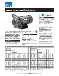
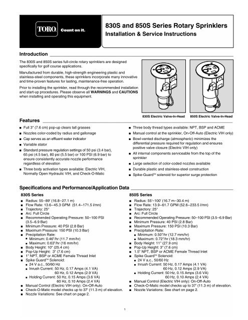
830S and <strong>850</strong>S Series Rotary Sprinklers<br />
<strong>Installation</strong> & Service Instructions<br />
Introduction ______________________________________________________________________<br />
The 830S and <strong>850</strong>S series full-circle rotary sprinklers are designed<br />
specifically for golf course applications.<br />
Manufactured from durable, high-strength engineering plastic and<br />
stainless-steel <strong>com</strong>ponents, these sprinklers incorporate many innovative<br />
and time-proven features for lasting, maintenance-free operation.<br />
Prior to installing the sprinkler, read through the re<strong>com</strong>mended installation<br />
and start-up procedures. Please observe all WARNINGS and CAUTIONS<br />
when installing and operating this equipment.<br />
ON<br />
A U T O<br />
830S Electric Valve-In-Head<br />
<strong>850</strong>S Electric Valve-In-Head<br />
Features _______________________________________________________________________________<br />
■<br />
■<br />
■<br />
■<br />
■<br />
■<br />
Full 3" (7.6 cm) pop-up clears tall grasses<br />
Nozzles color-coded by radius and gallonage<br />
Cap serves as an effluent water indicator<br />
Variable stator<br />
Standard pressure regulation settings of 50 psi (3.4 bar),<br />
65 psi (4.5 bar), 80 psi (5.5 bar) or 100 PSI (6.9 bar) to<br />
ensure consistently accurate nozzle performance<br />
regardless of elevation<br />
Three body activation types available: Electric VIH,<br />
Normally Open Hydraulic VIH, and Check-O-Matic<br />
■<br />
■<br />
■<br />
■<br />
■<br />
■<br />
■<br />
Three body thread types available: NPT, BSP and ACME<br />
<strong>Manual</strong> control at the sprinkler, On-Off-Auto (Electric VIH only)<br />
Bowl-vented discharge (atmospheric) minimizes the<br />
differential pressure required for regulation and ensures<br />
positive valve closure (Electric VIH only)<br />
All internal <strong>com</strong>ponents serviceable from the top of the<br />
sprinkler<br />
Large selection of color-coded nozzles available<br />
Durable plastic and stainless-steel construction<br />
Spike-Guard TM solenoid for superior surge protection<br />
Specifications and Performance/Application Data _______________________________________<br />
830S Series<br />
<strong>850</strong>S Series<br />
■ Radius: 55–89' (16.8–27.1 m)<br />
■ Radius: 55'–100' (16.7 m–30.4 m)<br />
■ Flow Rate: 13.6–45.3 GPM (51.4–171.5 l/mn)<br />
■ Flow Rate: 13.9–61.7 GPM (52.6–233.5 l/mn)<br />
■ Trajectory: 25°<br />
■ Trajectory: 25°<br />
■ Arc: Full Circle<br />
■ Arc: Full Circle<br />
■ Re<strong>com</strong>mended Operating Pressure: 50–100 PSI<br />
■ Re<strong>com</strong>mended Operating Pressure: 50–100 PSI (3.5–6.9 Bar)<br />
(3.5–6.9 Bar)<br />
■ Minimum Pressure: 40 PSI (2.8 Bar)<br />
■ Minimum Pressure: 40 PSI (2.8 Bar)<br />
■ Maximum Pressure: 150 PSI (10.3 Bar)<br />
■ Maximum Pressure: 150 PSI (10.3 Bar)<br />
■ Precipitation Rate:<br />
■ Precipitation Rate:<br />
■ Minimum: 0.50"/hr (12.7 mm/hr)<br />
■ Minimum: 0.46"/hr (11.7 mm/hr)<br />
■ Maximum: 0.72"/hr (18.3 mm/hr)<br />
■ Maximum: 0.63"/hr (16 mm/hr)<br />
■ Body Height: 11" (27.9 cm)<br />
■ Body Height: 10" (25.4 cm)<br />
■ Pop-Up Height: 3" (7.6 cm)<br />
■ Pop-Up Height: 3" (7.6 cm)<br />
■ 1.5" NPT, BSP or ACME Female Thread Inlet<br />
■ 1" NPT, BSP or ACME Female Thread Inlet<br />
■ Spike Guard TM Solenoid:<br />
■ Spike Guard TM Solenoid:<br />
■ 24 V a.c., 50/60 Hz<br />
■ Inrush Current: 50 Hz, 0.17 Amps (4.1 VA)<br />
60 Hz, 0.12 Amps (2.9 VA)<br />
■ Holding Current: 50 Hz, 0.15 Amps (3.6 VA)<br />
■ 24 V a.c., 50/60 Hz<br />
■ Inrush Current: 50 Hz, 0.17 Amps (4.1 VA)<br />
60 Hz, 0.12 Amps (2.9 VA)<br />
■ Holding Current: 50 Hz, 0.15 Amps (3.6 VA)<br />
60 Hz, 0.10 Amps (2.4 VA)<br />
60 Hz, 0.10 Amps (2.4 VA)<br />
■ <strong>Manual</strong> Control (Electric VIH only): On-Off-Auto<br />
■ <strong>Manual</strong> Control (Electric VIH only): On-Off-Auto<br />
■ Check-O-Matic model checks up to 37' (11.3 m) of elevation.<br />
■ Check-O-Matic model checks up to 37' (11.3 m) of elevation. ■ Nozzle Variations: See chart on page 2.<br />
■ Nozzle Variations: See chart on page 2.<br />
1
830S Series Sprinkler Performance Data<br />
26.2 66 31.5 74 34.1 80<br />
36.5 83<br />
<strong>850</strong>S Series Sprinkler Performance Data<br />
31.8 73 32.7 75 36.1<br />
39.5<br />
79<br />
83<br />
41.6<br />
44.2<br />
83<br />
87<br />
48.1<br />
51.6<br />
85<br />
89<br />
Sprinkler Application Data<br />
Nozzle Color Code<br />
Sprinkler Spacing Guidelines<br />
Precipitation Rate Formulas<br />
Nozzle Main Inner Intermediate<br />
❚<br />
Square Spacing<br />
❚ Square-spaced sprinklers in pattern:<br />
1 Yellow Yellow Blue<br />
2 Blue Yellow Blue<br />
No wind - 55% of diameter<br />
4 mph wind - 50% of diameter<br />
8 mph wind - 45% of diameter<br />
GPM of full circle x 96.3<br />
(Spacing) 2<br />
3 Brown Yellow Orange<br />
4 Orange Yellow Orange<br />
5 Green White Gray<br />
6 Gray White Gray<br />
7 Black White Red<br />
8* Red White Red<br />
9* Beige White Beige<br />
*Used with <strong>850</strong>S series sprinklers only.<br />
❚<br />
❚<br />
Triangular Spacing<br />
No wind - 60% of diameter<br />
4 mph wind - 55% of diameter<br />
8 mph wind - 50% of diameter<br />
Single-Row Spacing<br />
No wind - 50% of diameter<br />
4 mph wind - 50% of diameter<br />
8 mph wind - 45% of diameter<br />
Note: Designing for zero (0) mph<br />
wind conditions is not re<strong>com</strong>mended.<br />
Design for worst wind conditions.<br />
❚ Triangular-spaced sprinklers in pattern:<br />
❚ Area and flow:<br />
GPM of full circle x 96.3<br />
(Spacing) 2 (0.866)<br />
Total GPM of zone x 96.3<br />
Total irrigated<br />
square feet of zone<br />
For additional information, refer to<br />
<strong>Toro</strong> Technical Data <strong>Manual</strong>,<br />
form number 490-1737.<br />
❚ Single row:<br />
GPM of full circle x 96.3<br />
(Spacing) (Scallop)<br />
2
O F<br />
ON<br />
A U T O<br />
<strong>Installation</strong> Procedure ___________________________________________________<br />
To assure maximum performance from your 800S series sprinklers, read these instructions<br />
<strong>com</strong>pletely prior to installation or service.<br />
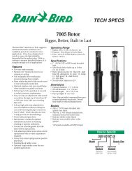
Constructing Swing Joints<br />
1. Construct or provide triple swing joints for each sprinkler as shown in Figure 1. Use PVC or<br />
ABS pipe nipple for the sprinkler connection.<br />
Note: On sites where the possibility of heavy equipment rolling over a sprinkler exists, the<br />
swing joint will flex preventing damage to the lateral or main lines. On a new installation in<br />
raw ground where the sprinklers are to be initially installed above the finished grade and<br />
lowered when new turf is established, the swing joint allows sprinkler repositioning without<br />
changing risers. This is a <strong>com</strong>mon and practical procedure which eliminates the problem of<br />
dirt being accidentally introduced into the lateral lines when a riser is changed.<br />
2. Flush lines thoroughly prior to installing sprinkler.<br />
3. Apply Teflon tape on riser threads (not required on ACME threads). Install sprinkler to riser and tighten.<br />
CAUTION: Use only Teflon tape on riser threads. Use of pipe dope or other types of sealing <strong>com</strong>pounds can cause<br />
deterioration of sprinkler body threads.<br />
Connecting Control Wires (Electric Models Only)<br />
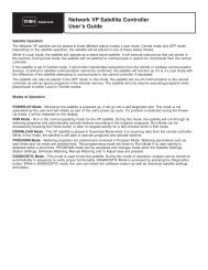
1. Route control wires to sprinklers. Provide extra wire at sprinkler to allow for height adjustment. One <strong>com</strong>mon wire and station<br />
wire is required for each sprinkler. See Wire Sizing Chart, Table 1 for proper application.<br />
Note: Wire length data provided in Table 1 is the sum of the station and <strong>com</strong>mon wire legs. See example in Figure 2.<br />
Table 1: Wire Sizing Chart<br />
Figure 1<br />
Total Wire Length Between Controller and Sprinkler<br />
Voltage AWG mm 2 Voltage Drop Circular Mils 1 Sprinkler 2 Sprinklers 3 Sprinklers 4 Sprinklers<br />
23 14/14 2.5/2.5 4 4100 6571' 2003 m 3285' 1001 m 2190' 668 m 1643' 501 m<br />
23 14/12 2.5/4.0 4 5315 8518' 2596 m 4259' 1298 m 2839' 865 m 2129' 649 m<br />
23 14/10 2.5/5.5 4 7250 11619' 3541 m 5809' 1771 m 3873' 1180 m 2905' 886 m<br />
23 12/12 4.0/4.0 4 6530 10465' 3190 m 5232' 1595 m 3488' 1063 m 2616' 798 m<br />
23 12/10 4.0/5.5 4 8465 13566' 4135 m 6783' 2067 m 4522' 1378 m 3391' 1034 m<br />
23 12/8 4.0/7.0 4 11515 18454' 5625 m 9227' 2812 m 6151' 1875 m 4613' 1406 m<br />
23 10/10 5.5/5.5 4 10400 16667' 5080 m 8333' 2540 m 5556' 1693 m 4167' 1270 m<br />
24 14/14 2.5/2.5 5 4100 8213' 2503 m 4107' 1252 m 2738' 835 m 2053' 626 m<br />
24 14/12 2.5/4.0 5 5315 10647' 3245 m 5324' 1623 m 3549' 1082 m 2662' 812 m<br />
24 14/10 2.5/5.5 5 7250 14523' 4427 m 7262' 2213 m 4841' 1476 m 3631' 1107 m<br />
24 12/12 4.0/4.0 5 6530 13081' 3987 m 6540' 1993 m 4360' 1329 m 3270' 997 m<br />
24 12/10 4.0/5.5 5 8465 16957' 5168 m 8479' 2584 m 5652' 1723 m 4239' 1292 m<br />
24 12/8 4.0/5.5 5 11515 23067' 7031 m 11533' 3515 m 7689' 2344 m 5767' 1758 m<br />
24 10/10 5.5/5.5 5 10400 20833' 6350 m 10417' 3175 m 6944' 2117 m 5208' 1581 m<br />
2. Attach control wires to solenoid leads using an<br />
approved waterproof splicing method.<br />
Figure 2<br />
CAUTION: All wire splices and field<br />
connections must be waterproofed to prevent<br />
short circuit to ground and subsequent controller<br />
damage.<br />
Connecting Hydraulic Control Tubing<br />
1. Route control tubing from the controller to the<br />
sprinkler location(s).<br />
Note: Leave an 18" (45.7 cm) service loop of tubing<br />
at each sprinkler to facilitate movement of sprinkler<br />
and service operations. Refer to Table 2 for tubing<br />
run length and sprinkler elevation information.<br />
2. Flush tubing thoroughly to remove all air and debris.<br />
3. Remove the tube retainer and poly cap from the<br />
tubing adapter at the base of the sprinkler.<br />
4. Slide the tube retainer over the end of the control<br />
tubing and attach tubing to adapter.<br />
5. Slide tube retainer over adapter area to secure tubing.<br />
Table 2: Hydraulic Control Systems<br />
Station Wire = 1095' (334m)<br />
Common Wire = 1095' (334m)<br />
Total Wire Length = 2190' (668m)<br />
Maximum Distance<br />
Type of System* From Controller Elevation Restrictions<br />
Normally Open (01)<br />
Valve elevation should not exceed<br />
with 3/16" Control Tubing 500' 25' ABOVE controller elevation or<br />
70' BELOW controller elevation.<br />
Normally Open (01)<br />
Valve elevation should not exceed<br />
with 1/4" Control Tubing 1000' 25' ABOVE controller elevation or<br />
70' BELOW controller elevation<br />
* - All hydraulic connections on <strong>Toro</strong> valves are 1 ⁄4" insert type.<br />
- Control line pressure must be equal to or greater than mainline pressure.<br />
- Control line pressure range is 40 to 150 PSI.<br />
3
System Start Up _________________________________________________________<br />
The following is a re<strong>com</strong>mended procedure that will protect system <strong>com</strong>ponents during system start-up. The procedure is based on a<br />
velocity fill rate of less than 2' (.61 m) per second. See Table 3 below.<br />
Table 3: Re<strong>com</strong>mended System Fill Rate<br />
Pipe Size Flow Velocity Pipe Size Flow Velocity<br />
in. cm GPM LPM ft/sec m/sec in. cm GPM LPM ft/sec m/sec<br />
1/2 1.3 2 7.6 1.60 0.49 3 7.6 45 170.3 1.86 0.57<br />
3/4 1.9 3 11.4 1.92 0.59 4 10.1 75 283.9 1.87 0.57<br />
1 2.5 5 18.9 1.50 0.46 6 15.2 150 567.8 1.73 0.53<br />
1-1/4 3.1 10 37.9 1.86 0.57 8 20.2 250 946.3 1.70 0.52<br />
1-1/2 3.8 10 37.9 1.41 0.43 10 25.4 450 1703.0 1.97 0.60<br />
2 5.0 20 75.7 1.80 0.55 12 30.5 500 1893.0 1.55 0.47<br />
2-1/2 6.4 30 113.6 1.84 0.56<br />
1. Use a jockey pump only to fill the system at a velocity fill rate of less than 2' (0.61 m) per second.<br />
CAUTION: Failure to <strong>com</strong>ply with re<strong>com</strong>mended fill rate will increase line pressure resulting in a water hammer<br />
effect that could damage sprinklers and piping <strong>com</strong>ponents. See Warning above.<br />
2. At all tees and greens use quick coupler keys with quick coupler valves to bleed air from the system lines during the filling<br />
process. For best results, do not <strong>com</strong>press air and then relieve it – bleed the air constantly while filling the system.<br />
3. After water has filled all lines and all air is removed, remove the quick coupler keys.<br />
Pilot Valve Operation (Electric Models Only) ________________________________________<br />
The pilot valve controls the operation of the main valve located in the base of the sprinkler body. The main valve is operated by the release<br />
of water metered through the pilot valve when it is activated either manually at the sprinkler or by the irrigation system controller.<br />
The pilot valve regulates the water pressure to the sprinkler nozzle. Pressure regulation <strong>com</strong>pensates for large variations within the<br />
system and maintains a constant pressure for optimum sprinkler operation. The pilot valve is factory set to regulate one of four<br />
pressure levels: 50 psi (3.4 bar), 65 psi (4.5 bar), 80 psi (5.5 bar) or 100 PSI (6.9 bar).<br />
The sprinkler operation mode is set using a <strong>Toro</strong> Selector Tool (P/N 995-15) inserted through the body flange onto the pilot valve D-<br />
shaped selector cam. The "AUTO" mode permits automatic operation from the system controller. The "ON" mode opens the main<br />
valve for manual operation and "OFF" mode prevents the main valve from opening.<br />
Troubleshooting _________________________________________________________<br />
■ Pilot Valve<br />
Possible equipment failures with causes and corrective action are listed below.<br />
PROBLEM<br />
SPRINKLER WILL<br />
NOT TURN ON<br />
SPRINKLER WILL<br />
NOT SHUT OFF<br />
WARNING<br />
NEVER STAND OR LEAN OVER THE SPRINKLER WHILE THE IRRIGATION SYSTEM IS BEING FILLED,<br />
DURING MANUAL OR AUTOMATIC OPERATION OR WHEN PERFORMING SPRINKLER SERVICE<br />
PROCEDURES. DIRECT CONTACT WITH IRRIGATION SPRAY, A FAILED OR IMPROPERLY INSTALLED<br />
SPRINKLER CONNECTION OR SPRINKLER COMPONENTS FORCIBLY EJECTED UPWARD UNDER<br />
PRESSURE CAN CAUSE SERIOUS INJURY.<br />
POSSIBLE CAUSE – CORRECTIVE ACTION<br />
(a) No 24 VAC to coil assembly. (Electric Models)<br />
– Measure voltage with a Digital Volt Meter (DVM). Check wiring and controller program.<br />
– Refer to Controller Operating Instructions.<br />
(b) Selector cam in "OFF" position.<br />
– Set to "AUTO" position.<br />
(c) Debris in pilot valve assembly.<br />
– Disassemble and remove all debris. (See Servicing Pilot Valve page 11.)<br />
(d) Insufficient pressure in controller supply line and/or sprinkler control tube. (N.C. Models)<br />
– Check pressure.<br />
(a) Constant 24 VAC from controller. (Electric Models)<br />
– Check for voltage using a DVM. If voltage is present, disconnect wire.<br />
If sprinkler closes, service controller. Refer to Controller Service <strong>Manual</strong>.<br />
(b) Selector cam in manual "ON" position.<br />
– Set to "AUTO" or "OFF" position.<br />
(c) Debris in pilot valve assembly.<br />
– Disassemble and remove all debris. (See Servicing Pilot Valve page 11.)<br />
(d) Constant pressure from controller. (N.C. Models)<br />
– Check pilot valve at controller for constant flow.<br />
– Check elevation differential. Valve elevation should not exceed 0' above<br />
controller elevation or 70' (21.3 m) below controller elevation.<br />
4
■ Sprinkler Assembly<br />
PROBLEM<br />
POSSIBLE CAUSE – CORRECTIVE ACTION<br />
SPRINKLER WON'T ROTATE (a) Debris wedged between stator and turbine.<br />
– Remove obstruction.<br />
(b) Drive assembly defective.<br />
– Replace drive assembly.<br />
(c) Nozzle base assembly defective.<br />
– Replace nozzle base assembly.<br />
HEAD STICKS UP (a) Dirt in riser assembly.<br />
– Flush out. (See Flushing Procedure on page 11.)<br />
(b) Damaged or missing return spring.<br />
– Replace.<br />
(c) Damaged riser.<br />
– Replace.<br />
POOR DISTRIBUTION PATTERN (a) Nozzle plugged with debris.<br />
– Clean or replace nozzle.<br />
(b) Nozzle orifice damaged.<br />
– Replace nozzle.<br />
■ Main Valve<br />
(c) Low operating pressure.<br />
– Determine why system overloaded and correct.<br />
PROBLEM<br />
POSSIBLE CAUSE – CORRECTIVE ACTION<br />
VALVE WON'T CLOSE (a) Continuous 24 VAC to sprinkler.<br />
(Electric )<br />
– Check controller for voltage source.<br />
(b) Leak in pilot valve assembly.<br />
– Replace pilot valve assembly.<br />
(c) Plugged supply screen on piston.<br />
– Clean or replace screen.<br />
(d) <strong>Manual</strong> control selector on pilot valve assembly turned to "ON" position.<br />
– Turn to "AUTO" position.<br />
(e) Plunger movement restricted.<br />
– Inspect and clean or replace.<br />
(f) Valve cylinder misaligned with sprinkler body <strong>com</strong>munication tube.<br />
– Remove valve assembly and install correctly.<br />
(g) Foreign object keeping valve from seating.<br />
– Remove, clean and check valve for damage. Replace if necessary.<br />
(h) Damaged piston seal or piston assembly.<br />
– Replace valve assembly.<br />
VALVE WON'T CLOSE (a) Leak in control tubing.<br />
(Hydraulic)<br />
– Isolate and repair.<br />
(b) Pilot valve leak in controller.<br />
– Confirm by observing constant dripping from discharge line of controller.<br />
Refer to Controller Service <strong>Manual</strong>.<br />
(c) Valve cylinder misaligned with sprinkler body <strong>com</strong>munication tube.<br />
– Remove valve assembly and install correctly.<br />
(d) Foreign object keeping valve from seating.<br />
– Remove, clean and check valve for damage. Replace if necessary.<br />
(e) Damaged piston seal or piston assembly.<br />
– Replace valve assembly.<br />
VALVE WON'T OPEN (a) Control (field) wires severed.<br />
(Electric)<br />
– Isolate and repair.<br />
(b) No power to controller.<br />
– Establish controller power.<br />
(c) No power from controller to solenoid.<br />
– Check for blown fuse and replace.<br />
(d) <strong>Manual</strong> control selector on pilot valve assembly turned to "OFF" position.<br />
– Turn to "AUTO" position.<br />
(e) Pilot valve solenoid inoperative.<br />
– Remove and replace.<br />
(f) Pilot valve plunger movement restricted.<br />
– Inspect, clean and/or replace.<br />
(g) No supply from main valve.<br />
– Debris in control tube, main valve assembly and/or <strong>com</strong>munication passages in<br />
body. Flush thoroughly.<br />
5
VALVE WON'T OPEN (a) Plugged controller discharge line or discharge port in pilot valve.<br />
(Hydraulic)<br />
– Verify by checking for discharge at discharge line when station is<br />
activated. If no discharge, refer to Controller Service <strong>Manual</strong>.<br />
SPRINKLER WEEPING (a) Damaged or blocked valve seat.<br />
(Slow leak in valve)<br />
– Remove blockage and, if necessary, replace valve assembly.<br />
(b) Damaged piston seal or piston assembly.<br />
– Replace valve assembly.<br />
(c) Low pressure on supply line .<br />
– Check for low pressure reason and correct.<br />
(d) Elevation of normally closed sprinkler exceeds 75' (22.9 m) differential.<br />
SEVERAL VALVES ON DIFFERENT (a) Control tubing leak which lowers supply pressure to other stations.<br />
STATIONS FAIL TO CLOSE<br />
– Turn controller from station to station until a station is reached where<br />
(Hydraulic)<br />
only valves on that station stay open. The leak would be in the tubing<br />
on that station. Isolate and repair.<br />
(b) Leak in supply line to controller.<br />
– Verify by checking pressure in all control lines.<br />
(c) Leak in controller pilot valve.<br />
– Verify by constant discharge from controller.<br />
(d) Plugged supply line filter.<br />
– Replace filter if more than 3 psi (0.21 bar) differential exists.<br />
Servicing Procedures<br />
____________________________________________________<br />
The 800S series sprinklers are designed to provide the user trouble-free operation for many years without scheduled maintenance. If<br />
it be<strong>com</strong>es necessary to disassemble the sprinkler to correct a malfunction or replace a <strong>com</strong>ponent, all internal parts of the sprinkler<br />
can be accessed from the top. Refer to the Troubleshooting Procedure in this manual in the event of a malfunction. Some special<br />
tools are required for disassembly and/or maintenance of the sprinkler and are available from your <strong>Toro</strong> dealer.<br />
WARNING<br />
NEVER STAND OR LEAN OVER THE SPRINKLER WHILE THE IRRIGATION SYSTEM IS BEING FILLED,<br />
DURING MANUAL OR AUTOMATIC OPERATION OR WHEN PERFORMING SPRINKLER SERVICE<br />
PROCEDURES. DIRECT CONTACT WITH IRRIGATION SPRAY, A FAILED OR IMPROPERLY INSTALLED<br />
SPRINKLER CONNECTION OR SPRINKLER COMPONENTS FORCIBLY EJECTED UPWARD UNDER<br />
PRESSURE CAN CAUSE SERIOUS INJURY.<br />
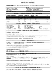
Servicing Sprinkler Mechanism<br />
Note: Refer to Figure 3 for the following procedure.<br />
1. Remove cap screw (1) and cap (3).<br />
2. Insert hooked end of multi-purpose tool (P/N 995-83) into slot in snap<br />
ring (8). Pull snap ring inward toward the sprinkler assembly, then<br />
upward to remove from the snap ring groove in sprinkler body.<br />
3. Insert hooked end of multi-purpose tool into slot over inner nozzle (7)<br />
and pull riser assembly out of sprinkler body.<br />
4. Grasp return spring (11) and riser (13) firmly and hold in place while<br />
removing nozzle base (5). Turn nozzle base assembly counterclockwise<br />
to remove.<br />
5. Carefully release tension from return spring.<br />
6. Remove spring and seal retainer/o-ring assembly (9 and 10).<br />
7. Remove rock screen (16) from bottom of riser assembly by turning it<br />
counterclockwise with edge of multi-purpose tool or tips of snap ring<br />
pliers (P/N 995-100).<br />
8. Remove o-ring (12) from top of riser assembly.<br />
9. Remove drive assembly (14) and stator (15) from riser assembly by<br />
carefully pressing on end of threaded shaft.<br />
10. Using a 5/8" nut driver (P/N 995-99), unscrew main nozzle (4) from<br />
nozzle base assembly.<br />
11. Using a 7/16" nut driver (P/N 995-79), unscrew two inner nozzles<br />
(6 and 7) from nozzle base assembly.<br />
12. Thoroughly clean and inspect all parts and replace as necessary.<br />
Reassemble in the reverse order.<br />
Note: During reassembly, ensure snap ring is correctly installed and<br />
fully seated in snap ring groove.<br />
Figure 3<br />
9<br />
4<br />
1<br />
2<br />
3<br />
5<br />
6<br />
7<br />
8<br />
10<br />
11<br />
12<br />
13<br />
14<br />
15<br />
16<br />
6
Servicing Main Valve<br />
WARNING<br />
IF THE VALVE SNAP RING IS DIFFICULT TO REMOVE, RESIDUAL WATER PRESSURE MAY BE<br />
REMAINING IN THE SYSTEM. TO PREVENT POSSIBLE SERIOUS INJURY DUE TO VALVE BEING<br />
EJECTED UPWARD UNDER PRESSURE, CONFIRM THE FOLLOWING CONDITIONS EXIST PRIOR TO<br />
REMOVING THE SNAP RING AND VALVE:<br />
A. WATER SUPPLY TO SPRINKLER IS SHUT OFF AT SOURCE.<br />
B. All PRESSURE IS BLED FROM SYSTEM, INCLUDING CONTROL TUBES.<br />
C. AC POWER IS DISCONNECTED AT SOURCE.<br />
1. See WARNING above. To remove valve assembly, squeeze<br />
snap ring ears together with snap ring pliers (P/N 995-100) and<br />
remove snap ring from sprinkler body. See Figure 4.<br />
2. Use valve removal tool P/N 995-08 for 830S or 995-09 for <strong>850</strong>S<br />
to remove valve assembly from base of sprinkler body. Valve<br />
removal tool is inserted into sprinkler body and pushed through<br />
valve ribs. A slight twist will catch tool under ribs enabling valve<br />
removal by pulling straight up and out. See Figure 5.<br />
Note: If valve removal tool is not available, use snap ring pliers<br />
to grasp rib of valve cylinder assembly and pull up and out of<br />
sprinkler body.<br />
3. Reinstall valve assembly using valve insertion tool P/N 995-76<br />
for 830S or 995-101 for <strong>850</strong>S as follows:<br />
• Load snap ring on insertion tool carrier with stepped side<br />
against carrier as shown in Figure 6. While holding snap ring in<br />
<strong>com</strong>pressed position, slide retainer clip in to hold snap ring ears<br />
• Load valve assembly on carrier as shown.<br />
• Locate position of <strong>com</strong>munication tube in bottom of sprinkler body and orient insertion tool accordingly.<br />
• Insert tool straight down into sprinkler body aligning bosses on t-handle with holes on sprinkler body flange. When valve<br />
assembly clears vertical side wall ribs inside body, pull up on snap ring release mechanism (<strong>850</strong>S models only) and press valve<br />
assembly into position. Snap ring will lock into groove when properly installed. Remove insertion tool and check snap ring to<br />
confirm that it is fully seated in groove.<br />
Figure 6<br />
Figure 4<br />
Snap Ring In<br />
Retainer Clip<br />
Figure 5<br />
Snap Ring Release<br />
Mechanism<br />
Stepped Side<br />
of Snap Ring<br />
Valve Assembly<br />
Orientation In Carrier<br />
Valve Assembly<br />
Pressed Into Position<br />
Snap Ring<br />
Released<br />
7
Servicing Pilot Valve<br />
WARNING<br />
NEVER STAND OR LEAN OVER THE SPRINKLER WHILE THE IRRIGATION SYSTEM IS BEING FILLED,<br />
DURING MANUAL OR AUTOMATIC OPERATION OR WHEN PERFORMING SPRINKLER SERVICE<br />
PROCEDURES. DIRECT CONTACT WITH IRRIGATION SPRAY, A FAILED OR IMPROPERLY INSTALLED<br />
SPRINKLER CONNECTION OR SPRINKLER COMPONENTS FORCIBLY EJECTED UPWARD UNDER<br />
PRESSURE CAN CAUSE SERIOUS INJURY.<br />
Note: Refer to Figure 7 for the following procedure.<br />
1. Make sure that the water supply to sprinkler is<br />
positively shut off and any residual pressure<br />
has been bled off. If the sprinkler is<br />
pressurized, main valve will open when the<br />
pilot valve is disconnected from control tube.<br />
2. Carefully remove turf and soil from side of<br />
sprinkler to expose pilot valve and control<br />
tubing.<br />
3. Remove two retaining screws from the pilot<br />
valve housing (1).<br />
4. Pull the pilot valve assembly away from the<br />
sprinkler body and cut the control tubing just<br />
below tube retainer. Unless pilot valve has<br />
been previously removed, control tubing<br />
length will be sufficient for re-connection.<br />
5. Remove tube retainer and remaining piece of<br />
control tubing from valve body fitting.<br />
8. Pull pilot valve body assembly out of<br />
housing.<br />
6. Remove solenoid (2) by turning it<br />
counterclockwise.<br />
7. Remove selector shaft assembly (8) and<br />
plunger assembly (3). (The selector shaft<br />
retains the plunger in the valve body.)<br />
9. Remove diaphragm assembly (10), piston (9),<br />
spring (8) and o-ring (4).<br />
Figure 7<br />
10. Thoroughly clean and inspect all parts. Replace damaged parts as necessary and reassemble in reverse order.<br />
Note: Refer to Illustrated Parts Breakout Book, form number 368-0044 for part numbers.<br />
2<br />
3<br />
4<br />
5<br />
6<br />
7<br />
8<br />
1<br />
9<br />
10<br />
Flushing Sprinkler _______________________________________________________<br />
WARNING<br />
NEVER STAND OR LEAN OVER THE SPRINKLER WHILE THE IRRIGATION SYSTEM IS BEING FILLED,<br />
DURING MANUAL OR AUTOMATIC OPERATION OR WHEN PERFORMING SPRINKLER SERVICE<br />
PROCEDURES. DIRECT CONTACT WITH IRRIGATION SPRAY, A FAILED OR IMPROPERLY INSTALLED<br />
SPRINKLER CONNECTION OR SPRINKLER COMPONENTS FORCIBLY EJECTED UPWARD UNDER<br />
PRESSURE CAN CAUSE SERIOUS INJURY.<br />
1. With sprinkler operating, carefully step down on center of cap several times. Water will flow around riser and flush out debris.<br />
2. Cycle sprinkler on and off several times to check for proper retraction. Cap should be even with top of body flange when fully<br />
retracted. If riser sticks in up position, check for debris lodged between riser and body. Flush out all debris. Remove sprinkler<br />
mechanism if necessary.<br />
© 2002 The <strong>Toro</strong> Company, Irrigation Division Form Number 373-0243 Rev. A