NW LTC Plus Controller Users Guide - Century Equipment
NW LTC Plus Controller Users Guide - Century Equipment
NW LTC Plus Controller Users Guide - Century Equipment

You also want an ePaper? Increase the reach of your titles
YUMPU automatically turns print PDFs into web optimized ePapers that Google loves.
Table of Contents<br />
<strong>Controller</strong> Components................................................. 2<br />
Selecting Control Options ............................................ 3<br />
Before Programming the <strong>Controller</strong>…..........................4<br />
About The <strong>Controller</strong>’s Memory ................................... 4<br />
Set Satellite Operating Mode ........................................ 4<br />
Set Current Time and Day............................................. 5<br />
Set Station Run Times................................................... 5<br />
Set Program Start Time(s) ............................................ 6<br />
Set Active Day Watering Schedules ............................ 7<br />
• Calendar Schedule.................................................... 7<br />
• Interval Schedule ...................................................... 8<br />
Set Program Repeat and Soak ..................................... 9<br />
Program Operation Pause and Cancel ...................... 10<br />
Manual Control Operations ...................................10- 12<br />
Cycle Mode................................................................... 10<br />
Syringe Mode ............................................................... 11<br />
Multi-Manual Mode ...................................................... 12<br />
Set Satellite Address ................................................... 13<br />
Set Percent Adjust....................................................... 13<br />
Reviewing Program Information ................................ 14<br />
Special Functions................................................... 14-15<br />
Self Test........................................................................ 14<br />
Initialization .................................................................. 14<br />
Radio Calibration Test................................................. 15<br />
Link Monitor ................................................................ 15<br />
Troubleshooting .......................................................... 16<br />
Lithium Battery Installation (Optional)....................... 16<br />
Manual Output Switch Operation ............................... 17<br />
Power Indicator Lamps ............................................... 17<br />
Program Data Reference Form....................................18<br />
Power Specifications<br />
Line Voltage: 115/230 V a.c. 50/60 Hz (switchable),<br />
130 VA (100W)<br />
Current Draw (no load): 0.21A @ 115 V a.c., 60 Hz, 0.10A<br />
@ 230V, 50 Hz<br />
Current Draw (maximum load): 0.90A @ 115 V a.c, 60 Hz,<br />
0.42A @ 230 V a.c, 50 Hz<br />
Secondary Voltage Output: 24 V a.c., 3.2A (77 VA)<br />
Maximum Load Per Station Output: 0.75A (18 VA)<br />
Maximum Load Per Pump/Master Valve Output:<br />
0.75A (18 VA)<br />
Hardware Features<br />
Plastic or Painted Stainless Steel Cabinetry<br />
Front, Back and Top Locking Covers<br />
Removable Station Output and Common/Pump Modules<br />
Modular Station Output:<br />
16 to 64 stations in 8-station increments<br />
Fuses and Circuit Breakers<br />
Power Supply:<br />
1.5A On/Off Switch/Circuit Breaker – Main Power Input<br />
3.2A Fuse (Slow-Blow) – Field Output<br />
4A Circuit Breaker – Control Functions<br />
Communication Modem (optional): 3/4A (Fast-Blow)<br />
Pump/Common & Communication Surge Protection<br />
Module (optional): 1/2A (Fast-Blow)<br />
Electromagnetic Compatibility<br />
Domestic: This equipment has been tested and found to<br />
comply with the limits for a FCC Class A digital device,<br />
pursuant to part 15 of the FCC Rules. These limits are<br />
designed to provide reasonable protection against harmful<br />
interference when the equipment is operated in a<br />
commercial environment. The equipment generates, uses,<br />
and can radiate radio frequency energy and, if not<br />
installed and used in accordance with the instruction<br />
manual, may cause harmful interference to the radio<br />
communications. Operation in a residential area is likely to<br />
cause harmful interference in which case the user will be<br />
required to correct the interference at his own expense.<br />
International: This is a CISPR 22 Class A product. In a<br />
domestic environment, this product may cause radio<br />
interference, in which case the user may be required to<br />
take adequate measures.<br />
1
R<br />
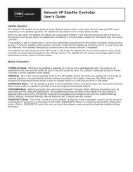
CONTROLLER COMPONENTS<br />
1<br />
Address<br />
Programs<br />
Time/Day<br />
% Adjust<br />
Central<br />
Stand<br />
Alone<br />
Off<br />
Run<br />
Times<br />
Start<br />
Times<br />
Active<br />
Days<br />
Tu<br />
1 2 3 4 5 6 7 8 9 10 11 12 13 14<br />
Week 1<br />
Week 2<br />
Cycle<br />
Syringe<br />
Multi<br />
Manual<br />
ENTER<br />
EXIT<br />
START<br />
STOP<br />
<strong>LTC</strong> <strong>Plus</strong><br />
TM<br />
2<br />
9<br />
10<br />
3<br />
4<br />
5<br />
6<br />
7<br />
11<br />
12<br />
13<br />
14<br />
8<br />
15<br />
16<br />
17<br />
(Plastic cabinet model shown)<br />
1. Control Panel Assembly<br />
2. Pump/Common Output Module<br />
3. Power Indicator Lamp – (5V) Control Functions<br />
4. 8-Station Output Module<br />
5. Pump/Master Valve Control Switch<br />
6. Optional Station Output Control Switches<br />
7. Optional Station Output Surge Protection Module<br />
8. Optional Communication & Pump/Common<br />
Surge Protection Module (Optional)<br />
9. Optional Communications Modem<br />
10. Power Indicator Lamp – (28V) Station Output<br />
11. Field Common Engage Push-Button Switch<br />
12. Field Common Indicator Lamp<br />
13. Standard 8-Station Terminal Block<br />
14. Main Power On/Off Switch/1.5A Circuit Breaker<br />
15. Input Voltage Select Switch<br />
16. 3.2A Fuse – Station Output<br />
17. 4.0A Circuit Breaker – Control Functions<br />
2
R<br />
Selecting Control Options<br />
A set of eight DIP switches, located beneath the upper left corner of the control panel (as illustrated below)<br />
is provided for the selection of optional control characteristics. Power to the controller must be turned Off<br />
and the control panel removed from the cabinet in order to make switch position changes. When power is<br />
switched on, the controller will automatically reconfigure to the new switch settings (with the exception of<br />
switch 5). See *Note below.<br />
The controller is shipped from the factory in the following configuration:<br />
Switch 1 ON and Switch 2 ON – Enables the controller to run eight programs concurrently.<br />
• Option – Switch 1 OFF and Switch 2 ON – Enables the controller to run only six programs<br />
concurrently.<br />
• Option – Switch 1 OFF and Switch 2 OFF – Enables the controller to run only four programs<br />
concurrently.<br />
• Option – Switch 1 ON and Switch 2 OFF – Enables the controller to run only two programs<br />
concurrently.<br />
Switch 3 ON – Time is displayed in a.m./p.m. format.<br />
• Option – Switch 3 OFF – Time is displayed in 24-hour format (00:00–23:59)<br />
Switch 4 ON – Pump output activates at the same time as station output.<br />
• Option – Switch 4 OFF – Pump output starts 5 seconds prior to station output. (Enables pump to reach<br />
pressure prior to station operation.)<br />
Switch 5 ON – Active day change occurs at midnight (12:00 a.m.[00:00])<br />
• Option – Switch 5 OFF – Day change occurs at 6:00 a.m. (06:00)<br />
*Note: This change requires initialization to activate. See page 14 for initialization procedure.<br />
Switches 6, 7 & 8 are non-functional.<br />
To change the DIP switch positions:<br />
1. Switch the power Off at controller power supply.<br />
2. Remove the timing mechanism from the top of the pedestal cabinet. (The cables attached to the timing<br />
mechanism can remain connected for this procedure).<br />
3. Locate the DIP switches mounted on top left corner of timing mechanism PCB.<br />
4. Using a pen tip or small screwdriver, reset the DIP switches as required. (Do not use a pencil for this<br />
procedure. Loose graphite from the pencil can damage the switch mechanism).<br />
5. Reinstall the timing mechanism and switch on the power.<br />
Address<br />
Programs<br />
Time/Day<br />
% Adjust<br />
Central<br />
Stand<br />
Alone<br />
Off<br />
Run<br />
Times<br />
Start<br />
Times<br />
Active<br />
Days<br />
Tu<br />
1 2 3 4 5 6 7 8 9 10 11 12 13 14<br />
Week 1<br />
Week 2<br />
Cycle<br />
Syringe<br />
Multi<br />
Manual<br />
ENTER<br />
EXIT<br />
START<br />
STOP<br />
<strong>LTC</strong> <strong>Plus</strong><br />
TM<br />
OFF<br />
ON<br />
1 2 3 4 5 6 7 8<br />
3
Before Programming the <strong>Controller</strong>…<br />
Please note the following important information before programming the Network <strong>LTC</strong> <strong>Plus</strong> controller<br />
for the first time. Although the controller is quite easy to program, it does have some programming<br />
and operating characteristics which will be helpful to know before starting.<br />
• *If power is interrupted to the satellite within one minute of a programming entry, the controller memory<br />
will be initialized (erased) when power is restored.<br />
• An audible “beep” tone occurs whenever a control panel key is pressed sufficiently. If the tone is not<br />
emitted, the key’s function will not be recognized.<br />
• Programming can only be accomplished in the Central or Stand Alone control modes.<br />
• The and (cursor keys) are used to navigate to the various program elements of the displays.<br />
When an element is selected, it begins flashing. Remember, a program element must be flashing<br />
before it can be changed.<br />
• The and (scroll keys) are used to scroll forward or backward through the program element<br />
values Holding either of these keys down for more than two consecutive seconds will initiate rapid<br />
scrolling.<br />
ENTER<br />
• The (Enter/Start key) must be pressed to enter a program change into memory.<br />
START<br />
• To exit a programming procedure, press the (function select) key to select the Time/Day mode.<br />
• During programming, the controller will automatically revert to Time/Day mode if a control panel key is<br />
not pressed for one minute.<br />
About the <strong>Controller</strong>’s Memory…<br />
The controller utilizes a special “Super Cap” capacitor which stores enough power to maintain the current<br />
time/date and the currently active program information for approximately 30 minutes. The controller will be<br />
otherwise inactive during the power outage. In most circumstances, the user-defined program information is<br />
unaffected by a loss of power and is stored in memory for several years. (See * above). When power is<br />
restored, any automatic programs operating prior to the power failure will resume from the point of interruption.<br />
Any manually started programs operating prior to the power failure will be canceled. Any automatic start<br />
times originating from the satellite or the central during the power failure will be ignored. In regions with frequent<br />
power interruptions, an optional lithium battery can be installed which will sustain real time and currently<br />
active program information for approximately 90 days of continuous duty. See “Battery Installation” on<br />
page 16 for more information.<br />
Set Satellite Operating Mode<br />
Selecting one of three operating modes determines how the satellite will operate.<br />
Central mode enables two-way communication between the satellite and the central controller. The satellite<br />
receives all operating commands (including the current time and day) from the central. No additional programming<br />
is required at the satellite. To operate in the Central mode, the satellite only requires an address<br />
which enables the central to locate it on the communication path. See “Set Satellite Address” on page 13.<br />
Stand Alone mode enables the satellite controller to operate independently from the central. Any data<br />
downloaded from the central will be ignored by the satellite while in this mode. However, information regarding<br />
field status and manual satellite operations will be uploaded to the central. When operating as a standalone<br />
controller, the Network <strong>LTC</strong> <strong>Plus</strong> maintains 16 independent watering programs. Each program is given<br />
specific operating information consisting of: Start Times – when and how often the program will start,<br />
Active Days – the daily watering routine in either a 14-Day Calendar or 29-Day Interval schedule, and Run<br />
Times – the operating duration time of each station assigned to the program. During a program event,<br />
stations assigned to the program operate one at a time in numerical sequence.<br />
Off mode terminates and prevents all automatic and manual controller operations.<br />
If programming the satellite for stand-alone operation, we recommend that you first plan out your irrigation<br />
schedule using the Program Data Reference Form provided on the back cover. Make photocopies of the<br />
form for each program you intend to use. Organizing your program information in this way will provide a<br />
complete overview of your automatic irrigation schedule and simplify the programming task. After the forms<br />
have been filled in, keep them with the satellite for future reference.<br />
1. Press the key as needed to select the Central, Stand Alone, or Off indicator.<br />
4
Set Current Time and Day<br />
Synchronizing the controller's clock with the current time and day is an important first step in the programming<br />
procedure. The timed events for all watering programs (when the satellite is in the Satellite Mode) are based on<br />
the settings you will make here.<br />
Use the following procedure to set the current time and day:<br />
1. Press as needed to select Time/Day indicator.<br />
2. Press – The hour digit(s) will begin flashing.<br />
3. Press or to increase or decrease hour digit(s).<br />
(Observe for correct a.m./p.m. time.)<br />
4. Press – Minute digits will begin flashing.<br />
5. Press or to increase or decrease minute digits.<br />
: AM<br />
:<br />
Mo<br />
1 2 3 4 5 6 7<br />
Week 2<br />
Example: Current Time 11:28 A.M.,<br />
Current Day Tuesday (10) Week 2.<br />
6. Press – Day abbreviation will begin flashing.<br />
7. Press or to select current day in either week of 14-day cycle.<br />
ENTER<br />
8. Press to store new information into controller memory.<br />
START<br />
:<br />
AM<br />
1 2 3 4 5 6 7<br />
Week 1<br />
Tu<br />
8 9 10 11 12 13 14<br />
Week 2<br />
Set Station Run Time<br />
Note the following Station Run Time characteristics:<br />
• Run time can be set from one minute to eight hours and 59 minutes in one-minute increments.<br />
• Each station can have a different assigned run time within each of 16 programs.<br />
1. Press to select the Programs indicator. The Run Time<br />
indicator will light. The program and station number will be shown in the<br />
left display, and the station run time will be shown in the right display.<br />
2. Press or to select the desired program number (1–16).<br />
Note: If the station run time has been adjusted to a value other than 100%<br />
using the % Adjust feature, the right display will alternate between the<br />
programmed run time and the adjusted run time. The % Adjust LED will<br />
light momentarily when the adjusted run time is displayed.<br />
Example Shown: Program 1, station 2, run time 1 hour and 23 minutes.<br />
3. Press – The station number digits will begin flashing.<br />
4. Press or to select the desired station number<br />
Note: The controller will automatically determine the number of station<br />
modules installed and limit the display accordingly.<br />
5. Press to select the run time display. The hours digit will begin<br />
flashing.<br />
6. Press or to select the desired hours of run time (0–8).<br />
Note: If station operation is not desired during a particular program,<br />
enter 0:00 run time.<br />
7. Press – The minutes digits will begin flashing.<br />
8. Press or to select desired minutes of run time (0–59).<br />
ENTER<br />
9. Press to enter the information.<br />
START<br />
10. Repeat steps 4–8 for each station as required.<br />
11. Press – Repeat steps 2–11 for all programs.<br />
5<br />
Program No.<br />
:<br />
Station No.<br />
:<br />
:<br />
:<br />
Run Time<br />
:<br />
Hours<br />
Minutes<br />
:<br />
:<br />
:
Set Program Start Time(s)<br />
This procedure will determine when each program will start during a 24 hour period. Note the following<br />
characteristics:<br />
• Each program can have from 1 to 12 start times.<br />
• Start times can be set to the minute.<br />
• Program operation can be prevented for any of the 12 start times by selecting OFF (no start time).<br />
• When operating in the Stand Alone mode, any new start times downloaded from the central will be ignored.<br />
• When operating in the Central mode, new start times downloaded from the central will be utilized.<br />
1. Press as needed to select the Program indicator.<br />
2. Press to select the Start Time indicator.<br />
3. Press or to select the desired program number (1 – 16).<br />
4. Press – Start time 01 will begin flashing and current start time<br />
will be shown.<br />
5. Press or to select desired start time number (1 – 12).<br />
6. Press – Hours digit(s) or “OFF” will begin flashing.<br />
7. Press or to adjust hours digits up or down.<br />
(Observe for correct a.m./p.m. time.)<br />
Note: If no start time is desired, select "OFF" – located between<br />
11 p.m. and 12 a.m. (23:00 and 00:00). Skip steps 8 & 9 and<br />
continue at step 10.<br />
Example shown: Program 1, start time 1 set to 2:30 a.m.<br />
8. Press – Minutes digits will begin flashing.<br />
9. Press or to adjust minutes digits up or down.<br />
ENTER<br />
10. Press to enter the information.<br />
START<br />
11. Repeat steps 5 – 10 for all desired start times for this program.<br />
12. Press to select another program number.<br />
13. Repeat steps 3 – 12 as required.<br />
Start Time No.<br />
Program No.<br />
:<br />
:<br />
:<br />
:<br />
Current<br />
Start Time<br />
:<br />
AM<br />
:<br />
AM<br />
6
Set Active Day Watering Schedules<br />
The active watering days for each program can be chosen using a Calendar schedule or an Interval<br />
schedule. The Calendar schedule enables active days to be selected within a 14-day (two week) cycle. The<br />
Interval Schedule enables active days to be selected by a specific interval, such as every day, every-other<br />
day, every-third day and so on – up to every twenty-ninth day.<br />
Select the active watering days for each program using either a Calendar schedule (below) or an Interval<br />
schedule (on page 8).<br />
Note the following programming characteristics:<br />
• Only one watering day schedule (Calendar or Interval) can be utilized for each program.<br />
• To prevent automatic operation of any program, all days in a Calendar Schedule can be deleted or<br />
Interval Day can be set to Off.<br />
To Set a Calendar schedule:<br />
1. Press as needed to select the Program indicator.<br />
2. Press to select the Active Days indicator.<br />
3. Press or until the desired program number (1 – 16) is<br />
flashing.<br />
4. Press – The schedule type will begin flashing.<br />
5. Press or until CA (Calendar) is flashing.<br />
6. Press – The current Calendar schedule is displayed and<br />
Sunday (Su) of week 1 is flashing.<br />
7. Choose to select or delete the indicated (flashing) day.<br />
• To select: Press – The day stops flashing and remains<br />
displayed and the next day starts flashing.<br />
• To delete: Press – The day disappears and next day starts<br />
flashing.<br />
8. Repeat step 7 to set the 14-day watering schedule.<br />
Note: To prevent automatic operation of the program, delete all 14<br />
days or, as an alternate method, select Interval “Off”. See page 8 for<br />
this procedure.<br />
Program No.<br />
Schedule Type<br />
(Calendar)<br />
:<br />
:<br />
:<br />
Su Mo We Fr Mo We Fr<br />
1 2 3 4 5 6 7<br />
Week 1<br />
8 9 10 11 12 13 14<br />
Week 2<br />
ENTER<br />
9. Press to enter the information into controller memory.<br />
START<br />
10. Repeat steps 3 – 9 for all programs requiring a Calendar<br />
schedule.<br />
Note: If an Interval watering schedule is not required, programming<br />
for automatic operation is now complete. When an automatic program<br />
starts, the displays will alternate between the time/day and program<br />
status. If two or more programs are operating concurrently, the display<br />
will alternate to show status of each program.<br />
:<br />
:<br />
AM<br />
:<br />
Fr<br />
Pgm #<br />
Sta #<br />
Sta Run Time<br />
7
Interval Schedule<br />
Scheduling active days by Interval enables a program to operate on a specific routine such as, every other<br />
day, or every fourth day, without regard to actual calendar days.<br />
The Interval schedule consists of two programmable numbers: The Interval Reference and the Interval Day.<br />
The Interval Reference number (01 – 29) determines how often an active watering day will occur. For<br />
example, entering 01 equals watering every day, 02 equals every other day and so on up to 29 for watering<br />
every 29th day. The Interval Day number (01 – 29 and Off) indicates when an active watering day will occur.<br />
The Interval Day number automatically decreases by one at the day changeover. An active watering day will<br />
occur when the Interval Day number is 01. As the day change occurs at the end of the active watering day,<br />
the Interval Day number will automatically update to display the number of days until the next active<br />
watering day.<br />
During initial programming, the Interval Day number can be set at any point in the interval to establish the<br />
position of the interval within the week or month. For example, you may select a 6-day interval (watering<br />
every sixth day) but choose to start the interval tomorrow by entering an Interval Day number of 02. After<br />
one day has elapsed, the interval will begin and the day will be active. At the end of the active day, the<br />
Interval Day number will reset to 06, indicating six days until the next scheduled watering.<br />
Note: The Interval Day number cannot be greater than the interval reference number. If attempted, the<br />
Interval Day number will automatically be reduced to equal the the Interval Reference number when the<br />
Enter/Start key is pressed.<br />
To set an Interval schedule:<br />
1. Press as needed to select the Program indicator.<br />
2. Press to select the Active Days indicator.<br />
3. Press or until the desired program number (1 – 16) is<br />
flashing.<br />
4. Press – The schedule type will begin flashing.<br />
Program No.<br />
Schedule Type<br />
(Interval)<br />
:<br />
:<br />
Interval<br />
Reference No.<br />
:<br />
5. Press or until In (Interval) is flashing<br />
6. Press –The Interval Reference digits will begin flashing.<br />
7. Press or to select desired Interval Reference number<br />
(01 – 29).<br />
8. Press – Interval Day number will begin flashing.<br />
9. Press or to select Interval Day (01 – 29).<br />
Example Shown: Watering every third day (03),<br />
starting tomorrow (02).<br />
Note: To prevent automatic operation of this program, select Off<br />
located between 00 and 29.<br />
:<br />
:<br />
:<br />
:<br />
:<br />
ENTER<br />
10. Press to enter information into controller memory.<br />
START<br />
11. Repeat steps 3 – 10 for each program requiring an Interval<br />
schedule.<br />
Note: Programming for automatic operation is now complete. When<br />
an automatic program starts, the displays will alternate between the<br />
time/day and program status. If two or more programs are operating<br />
concurrently, the display will alternate to show status of each program.<br />
:<br />
AM<br />
Fr<br />
:<br />
:<br />
8<br />
Pgm #<br />
Sta #<br />
Sta Run Time
Set Program Repeat and Soak<br />
This is an optional programming feature which enables a program to repeat its operating cycle from 0 – 3<br />
times (in addition to its initial cycle). A soak-in period from 0 – 59 minutes is placed between repeat cycles.<br />
1. Press as needed to select the Program indicator.<br />
2. Press or until the desired program number (1 – 16) is<br />
flashing.<br />
3. Press – 01 will begin flashing.<br />
4. Press – The letter "r" (repeat) will begin flashing.<br />
5. Press – The digit left of colon in the right side display will<br />
begin flashing.<br />
6. Press or to display desired number of repeats (0 – 3).<br />
7. Press – The digits right of colon will begin flashing.<br />
8. Press or to select a soak time (0 – 59 minutes).<br />
Example Shown: Program 1, 2 repeat cycles with a 10-minute soak<br />
time between cycles.<br />
ENTER<br />
9. Press to enter information into controller memory.<br />
START<br />
Program No.<br />
Station No.<br />
:<br />
:<br />
:<br />
Repeat<br />
Program 1<br />
No. of Repeats<br />
:<br />
:<br />
:<br />
2 Repeats<br />
10 minutes<br />
Soak Time<br />
10. Press – The Program number will begin flashing.<br />
11. Repeat steps 2 – 10 for all programs as required.<br />
Note: During the soak period between watering cycles, the displays<br />
will alternate between Time/Day and Repeat/Soak status.<br />
:<br />
:<br />
AM<br />
:<br />
Fr<br />
Program No.<br />
Repeats<br />
Remaining<br />
Soak Time<br />
Remaining<br />
9
Program Operation Pause and Cancel<br />
An operating program can be paused or canceled at any time as needed. The pause feature temporarily<br />
suspends program operation for up to 10 minutes. When operation resumes, the program continues from<br />
the point of interruption without loosing station run time. Use the cancel feature to terminate the program<br />
operation, returning the controller the the time and day mode.<br />
To pause program operation: Press the key while the program status is displayed. The right side<br />
STOP<br />
display will show a letter P indicating the program is Paused.<br />
Note: Program operation will resume automatically in 10 minutes if the Enter/Start key is not pressed.<br />
To resume program operation: Press the<br />
key.<br />
To cancel program operation: Either press the key two times, or press the key to select Off,<br />
STOP<br />
then press the key again as needed to select Central or Stand Alone mode.<br />
Manual Control Operations<br />
Manual operations can be initiated at any time and can occur concurrently with automatically started watering<br />
operations. Three types of manual operations are available:<br />
• Cycle mode to start complete or partial program cycle(s)<br />
• Syringe mode to enable all stations in a program to be operated for a temporary run time from<br />
1 – 30 minutes or 10 – 99%<br />
• Multi-Manual mode to provide simultaneous operation of up to 6 stations.<br />
Cycle Mode<br />
This mode enables you to start and run all or part of any automatic watering program. Full Cycle runs a<br />
complete cycle of any program selected. Partial Cycle starts the program cycle at any selected station, and<br />
runs only the stations (with programmed run time) which follow in the program cycle.<br />
Note: During a manual operation, all programmed repeat and soak operations will be ignored.<br />
■<br />
Full Cycle<br />
1. Press to select the Cycle indicator.The Program indicator will light and program 1 will be<br />
automatically selected.<br />
2. Press or until the desired program number (1 – 16) is flashing.<br />
3. Press to start the program watering cycle.The displays will alternate between the Time/Day and<br />
START<br />
program status displays.<br />
4. To start additional programs, repeat steps 2 – 3.<br />
Note: The maximum number of programs which can operate concurrently during manual operation is 4.<br />
■<br />
ENTER<br />
Partial Cycle<br />
1. Press to select Cycle indicator. Program 1 will be automatically selected.<br />
2. Press or until the desired program number (1 – 16) is flashing.<br />
3. Press – The first station number with a run time in the selected program will begin flashing.<br />
4. Press or as required to select the station number to begin the partial cycle.<br />
ENTER<br />
EXIT<br />
ENTER<br />
START<br />
EXIT<br />
5. Press to start the program watering cycle.The displays will alternate between the Time/Day and<br />
START<br />
program status displays.<br />
10
Syringe Mode<br />
The Syringe mode enables all stations with a programmed run time in a selected program to be operated for<br />
a short, temporary run time (syringe). The amount of run time for the syringe operation can be set from<br />
1 – 30 minutes or by a percentage of programmed station run time from 10% – 99%.<br />
To syringe all stations from 1 – 30 minutes:<br />
1. Press to select Syringe indicator.Program 1 will be<br />
automatically selected .<br />
2. Press or to select desired Program number (1 – 16).<br />
The Left display shows the program number and rt (run time in<br />
minutes). A 1-minute syringe time is automatically selected and shown<br />
in the right display. To increase the syringe run time, continue at step 3.<br />
If no increase is needed, continue at step 5.<br />
3. Press – The syringe time digits will begin flashing.<br />
4. Press or to select a syringe time (02 – 30 minutes).<br />
Program<br />
Number<br />
Run Time In<br />
Minutes<br />
:<br />
Syringe<br />
Run Time<br />
:<br />
:<br />
ENTER<br />
5. Press to start the syringe cycle. The displays will alternate<br />
START<br />
between the time/day and the program status.<br />
Note: Only the stations with a programmed run time in the program<br />
selected will operate during the syringe operation.<br />
:<br />
:<br />
AM<br />
:<br />
Fr<br />
To syringe from 10% – 99% of station run time:<br />
1. Repeat steps 1 and 2 above.<br />
2. Press The left display shows a % symbol. A 25% adjusted run<br />
time value is automatically selected and shown in the right display.<br />
To change the % value, continue at step 4; if no change is needed,<br />
continue at step 6.<br />
3. Press – Syringe % value (25%) will begin flashing.<br />
4. Press or to adjust run time value from 10% – 99%.<br />
ENTER<br />
5. Press to start the syringe cycle. The displays will alternate<br />
START<br />
between Time/Day and program status as shown above.<br />
Note: When the station run time remaining becomes less than one<br />
minute, the display will show 00. The display will continue to show 00<br />
while the remaining time of 59 seconds or less elapses.<br />
Program<br />
Number<br />
Station<br />
Number<br />
Program<br />
Number<br />
Run Time By<br />
Percentage<br />
:<br />
Syringe<br />
Time<br />
Remaining<br />
25%<br />
Adjusted Run<br />
Time % Value<br />
11
Multi-Manual Mode<br />
Up to six selected stations can be operated at the same time using Multi-Manual mode. A temporary run<br />
time from 1 to 59 minutes is given to each station for this operation.<br />
Caution: Prior to Multi-Manual operation, ensure that combined current draw of all stations operating<br />
at the same time (including pump relay) does not exceed 3.2 Amps (holding).<br />
1. Press to select the Multi-Manual indicator. The Program<br />
indicator will light and Station number 01 will be shown (flashing)<br />
in the left display.The right display will show 00 run time.<br />
2. Press or as needed to select the desired station.<br />
3. Press – The Run Time digits will begin flashing.<br />
Station Number<br />
Run Time<br />
:<br />
4. Press or as needed to select desired Run Time (01 – 59)<br />
ENTER<br />
5. Press – Selected station will start.<br />
START<br />
6. Repeat steps 2 – 5 to start up to five additional Stations. If the<br />
same run time is desired, skip steps 3 and 4.<br />
Note: Any additional stations entered while six stations are in<br />
operation will be ignored.<br />
Note: After 1 minute has elapsed, the displays will begin alternating<br />
between the time/day and the program status, showing (in sequence)<br />
each operating station and its remaining run time.<br />
:<br />
AM<br />
:<br />
Fr<br />
:<br />
:<br />
:<br />
12
Set Satellite Address<br />
The <strong>LTC</strong> satellite requires a unique address for identification by the central LCM within the network system. The<br />
address consists of a group number (1 – 50) and satellite number (1 – 500). A combination of up to 500 satellites<br />
may be defined. Satellites may only be assigned to one group. However, the same satellite number may be<br />
used for satellites in different groups. For example, satellite 001 in group 01 has a different address than satellite<br />
001 in group 04. The satellite address is based on the combination of the group and satellite numbers.<br />
Use the following procedure to assign the satellite address.<br />
1. Press to select Address indicator The displays show the<br />
current group and satellite numbers. The default address is group<br />
50, satellite 500.<br />
2. Press – Group number will begin flashing.<br />
3 Press or to select desired group number (01 – 50).<br />
4. Press – Satellite number will begin flashing.<br />
5. Press or to select desired satellite number (01 – 500).<br />
ENTER<br />
6. Press to enter the information.<br />
START<br />
Group<br />
Number<br />
<strong>Controller</strong><br />
Number<br />
Set Percent Adjust<br />
This feature enables the run time of all stations assigned to a program to be adjusted by the same<br />
percentage up or down in 1% increments. Run time percent adjustments can be applied to individual<br />
programs and/or globally to all programs.<br />
Note the following Percent Adjust characteristics:<br />
• Adjustable from 10% to 250% (100% is neutral position).<br />
• Adjusted station run time is displayed during program operation and while setting station run times.<br />
(See Note on page 5 regarding adjusted run time display.).<br />
• % adjust values will be reset to 100% when operated in the Central control mode.<br />
• Global adjust (P0) is applied to all programs in addition to individual program % adjust value.<br />
Example: A 40 minute run time with a 50% Individual program adjust value and 50% Global adjust value<br />
equals 10 minutes adjusted run time (40 x 50% = 20 x 50% = 10).<br />
1. Press to select % Adjust indicator. The displays show P0<br />
(Global adjust) and current % value. If global adjustment is desired,<br />
continue at step 3. If Global adjust is not desired, continue at step 2.<br />
2. Press or as needed to select desired program number.<br />
3. Press – The percentage digits will begin flashing.<br />
4. Press or to adjust the percentage up or down.<br />
Note: For programs P1 – P16, an OFF position is provided between the<br />
250% and 10% change point. Selecting OFF prevents the program from<br />
being affected by a global % adjustment and locks the program % adjust<br />
value at 100%.<br />
ENTER<br />
5. Press to enter the information.<br />
START<br />
6. Repeat steps 2 – 5 for all programs as required.<br />
Global Adjust<br />
(All Programs)<br />
Program<br />
Number<br />
100%<br />
120%<br />
13
Reviewing Program Information<br />
To review the current operating information entered for any program, use the procedure below. If you need<br />
to make changes to any portion of a program or the Time/Day setting, refer to the appropriate procedure in<br />
the programming section of this manual.<br />
1. Press to select the Program number indicator.<br />
2. Press or as needed to select the desired program number (1 – 16).<br />
3. Press to select the desired portion of program.<br />
4. Press or or as needed to step through program information.<br />
Special Functions<br />
Note: Station/pump outputs will be momentarily cycled on and off several times during the self test and<br />
Initialization procedures. To prevent possible operation of irrigation valves and pump relay, remove the 3.2A<br />
fuse or disconnect the field common wire(s) until the test is completed.<br />
■ Self Test<br />
The Self Test enables the <strong>LTC</strong> satellite to automatically perform a diagnostic check of all functions, LED<br />
indicators, LCD elements, internal circuits and station/pump outputs.<br />
To perform the self test:<br />
1. Turn off power supply switch.<br />
2. Press and hold key down while switching power on. Continue holding key down for 5 seconds,<br />
then release.<br />
During the first portion of the test, the displays will momentarily show the following information:<br />
• Software version installed (i.e., version 1.0 = 1 0)<br />
• Number of stations installed (i.e., 16 stations = 16 STA)<br />
• Diagnostic code (i.e., 00 000)<br />
• Memory chip number (i.e., EE1)<br />
Note: If the memory chip or timer chip is not functioning properly, EE1 Err or CLK Err will be displayed.<br />
The next portion of the test cycles all LED indicators and LCD elements and turns the station/pump outputs<br />
on and off.<br />
3. To end self test, press and keys simultaneously. Current time will be displayed (flashing). Press<br />
the<br />
EXIT<br />
STOP<br />
■ Initialization<br />
key to stabilize display.<br />
Note: Performing an initialization permanently erases all user defined program information from the<br />
satellite memory (except current time and day).<br />
To perform an initialization:<br />
1. Turn off power supply switch.<br />
2. Press and hold key down while switching power on. Continue holding key down for 5 seconds,<br />
then release.<br />
Note: The satellite will perform the same operation as the Self Test (as detailed above), however during the<br />
process all user defined information stored in the memory will be erased.<br />
3. To end initialization process, press and keys simultaneously. Current time will be displayed<br />
(flashing). Press the<br />
EXIT<br />
STOP<br />
key to stabilize display.<br />
14
Radio Calibration Test<br />
The radio calibration test enables the <strong>LTC</strong> to generate three different radio test patterns for use in radio<br />
network communications setup. If a radio is not connected, no indication is seen on the TM. The test<br />
patterns can be monitored by connecting an oscilloscope or headphones to the modem 2-wire connector.<br />
To Perform Radio Calibration Test:<br />
1. Turn off power to controller at power supply switch.<br />
2. Press and hold key while switching on the power. Continue holding down the key for 5 seconds.<br />
The left display will show CAL.<br />
3. Wait 30 seconds<br />
• Press<br />
• Press<br />
– A 1200 Hz test pattern will be generated for 30 seconds.<br />
– A 2200 Hz test pattern will be generated for 30 seconds.<br />
• Press<br />
ENTER<br />
START<br />
– An alternating 1200/2200 Hz test pattern will be generated for 30 seconds.<br />
EXIT<br />
4. Press to exit Radio Calibration Test mode.<br />
STOP<br />
Link Monitor<br />
Link Monitor enables any satellite communicating with the central to review the communications link status<br />
of all satellites within the network. During Link Monitor operation, the central continuously polls the network<br />
satellites in numerical sequence and rapidly displays the addresses accompanied by an audible “beep”. If a<br />
satellite does not respond to the central during the polling process, the satellite address remains displayed<br />
for two seconds and is accompanied by two additional beeps. After all satellites have been polled, the last<br />
satellite address in numerical sequence remains displayed for ten seconds. The polling sequence is<br />
repeated continuously until the Link Monitor is exited by pressing the Exit/Stop key.<br />
1. Press and hold down the key for five seconds to activate<br />
Link Monitor mode.<br />
Note: If this satellite is not connected to the network or if the LCM<br />
is not polling, 00 000 will be displayed.<br />
EXIT<br />
2. Press the key to exit the Link Monitor mode.<br />
STOP<br />
Group # Satellite #<br />
15
Troubleshooting<br />
If you experience a controller problem, check the programming for a possible programming error and the<br />
list of problems and solutions listed below. If the problem continues, contact your local Toro distributor<br />
for assistance.<br />
WARNING<br />
TO AVOID ELECTRICAL SHOCK HAZARD, ASSURE POWER SOURCE IS OFF BEFORE<br />
ATTEMPTING ANY CONTROLLER REPAIR. ALL REPAIRS SHOULD BE PERFORMED BY A<br />
QUALIFIED TECHNICIAN.<br />
Problem Probable Cause Remedy<br />
■ <strong>Controller</strong> inactive — no display<br />
■ <strong>Controller</strong> on — valve(s) not<br />
operating<br />
■ Pump does not operate<br />
■ Limited number of programs can<br />
be operated at a time<br />
■ a.m. or p.m. designation does not<br />
appear with clock time<br />
1. 4A control circuit breaker tripped.<br />
2. Power supply On/Off switch in<br />
Off (O) position.<br />
1. Improper valve connection(s).<br />
2. Station output module switch in Off<br />
position.<br />
3. 3.2A fuse blown.<br />
1. Pump output module control switch<br />
in Off position.<br />
2. Pump component malfunction.<br />
3. Improper pump connection(s).<br />
1. DIP switch #1 and #2 position.<br />
1. DIP switch #3 in Off position —<br />
time displayed in 24-hour format.<br />
1. Check output module switches. Set<br />
ALL switches to Auto or Off. Reset<br />
4A circuit breaker.<br />
2. Position switch in On (–) position.<br />
1. Check connections.<br />
2. Set output module switch to Auto<br />
position.<br />
3. Replace 3.2A fuse<br />
1. Set control switch to Auto position<br />
2. Repair or replace faulty pump<br />
components.<br />
3. Check connections.<br />
1. Check position of DIP switch #1 &<br />
#2. See page 3.<br />
1. Set DIP switch #3 to On position.<br />
See page 3.<br />
Lithium Battery installation (optional)<br />
An optional 3.9V lithium battery (P/N 363-2200) can be installed to sustain the controllers clock time and the<br />
currently active program information for approximately 90 days with no additional power applied.<br />
WARNING<br />
DANGER OF EXPLOSION IF BATTERY IS INSTALLED INCORRECTLY. REPLACE ONLY WITH<br />
THE SAME OR EQUIVALENT TYPE OF BATTERY. ALWAYS DISPOSE OF USED BATTERIES<br />
ACCORDING TO THE BATTERY MANUFACTURER’S INSTRUCTIONS.<br />
Procedure<br />
1. Turn off power to controller at power supply switch.<br />
2. Remove phillips screws from corners of control panel and<br />
carefully lift panel up.<br />
3. Turn control panel over, resting it face down on pedestal.<br />
Connector cables can remain attached to PCB for this<br />
procedure.<br />
4. Remove five phillips screws from back of control panel<br />
PCB and separate PCB from faceplate assembly.<br />
5. Locate battery pin sockets located on front side of PCB<br />
as shown at right. Insert battery carefully to avoid bending<br />
contact pins. The pins are unevenly spaced allowing the<br />
battery to be installed easily in one direction only. Do not<br />
force battery pins into sockets. See Warning above.<br />
6. Reassemble control panel assembly and reinstall into<br />
pedestal.<br />
7. Restore power to controller at power supply switch.<br />
16
Manual Output Switch Operation<br />
A 3-position switch is provided on the Pump/Com<br />
module for additional control of the pump relay<br />
circuit. In addition, the optional station terminal<br />
modules with optional control switches have one<br />
switch for each station output.<br />
The three switch positions control the circuits as<br />
follows:<br />
On – Manually activates the circuit. The pump or<br />
station will remain on until the switch is moved to the<br />
Auto or Off position.<br />
Off – Switches the circuit off, preventing pump or<br />
station operation from the satellite.<br />
Auto – The circuit is automatically activated by the<br />
controller during automatic or manual watering<br />
operation.<br />
As an added lightning protection measure, the field<br />
common circuit is normally open when the controller<br />
is inactive. Therefore, to use the field output control<br />
switches for manual operation, the common circuit must be engaged first. Press the Field Common<br />
Engage push button switch to activate the circuit. The Field Common Indicator Lamp will turn on when the<br />
circuit is active. The common circuit will automatically disconnect upon completion of an automatic or<br />
manually activated watering operation initiated through the timing mechanism. The circuit can also be<br />
disconnected by momentarily switching the power supply off.<br />
Caution: To prevent damage to the 3.2A field output circuit fuse, do not exceed 3.2A load when<br />
manually activating multiple field outputs.<br />
Power Indicator Lamps<br />
Two indicator lamps, as shown in the illustration at<br />
right, are provided to verify the presence of power to<br />
the control and field output circuits. In normal<br />
operating conditions, both lamps will be On. If both<br />
lamps are Off, no power is present. Ensure the<br />
power supply/circuit breaker switch is On. Also<br />
check the main power source circuit breaker and<br />
any additional power disconnection devices in the<br />
fixed wiring. If the left indicator lamp is Off, the 4A<br />
circuit breaker is open and must be reset. If the right<br />
indicator lamp is off, the 3.2A field output fuse is<br />
blown.<br />
HOT POST HOT POST HOT POST<br />
Control Circuit<br />
Indicator Lamp<br />
8-Station Module<br />
Retainer Screw<br />
Field Common<br />
Engage Switch<br />
Field Common<br />
Indicator Lamp<br />
Pump Circuit<br />
Switch<br />
Station Output<br />
Control Switches<br />
(Optional)<br />
Output Circuit<br />
Indicator Lamp<br />
WARNING<br />
IF FUSE REPLACEMENT IS REQUIRED,<br />
REPLACE WITH A FUSE OF THE SAME<br />
TYPE AND AMPERAGE RATING. FAILURE<br />
TO COMPLY CAN RESULT IN SERIOUS<br />
INJURY AND/OR EQUIPMENT DAMAGE<br />
DUE TO FIRE HAZARD.<br />
Power Supply<br />
On/Off Switch<br />
4A Control<br />
Circuit Breaker<br />
Removing and Installing 8-Station Modules<br />
1. Switch power supply Off<br />
2. Remove single screw from module.<br />
3. Pull module outward from top connector then<br />
upward from bottom connector (if installed).<br />
4. Install module in reverse order.<br />
Power Supply 5A<br />
Circuit Breaker<br />
3.2A Field<br />
Output Fuse<br />
Note: When adding modules, utilize the first available open position from left to right, front to back. Do<br />
not leave open spaces between modules.<br />
17
Program Data Reference Form<br />
Program Number_____<br />
Station Location<br />
Date_________<br />
1 ___________________ 17 ___________________ 33____________________ 49____________________<br />
2 ___________________ 18 ___________________ 34____________________ 50____________________<br />
3 ___________________ 19 ___________________ 35____________________ 51____________________<br />
4 ___________________ 20 ___________________ 36____________________ 52____________________<br />
5 ___________________ 21 ___________________ 37____________________ 53____________________<br />
6 ___________________ 22 ___________________ 38____________________ 54____________________<br />
7 ___________________ 23 ___________________ 39____________________ 55____________________<br />
8 ___________________ 24 ___________________ 40____________________ 56____________________<br />
9 ___________________ 25 ___________________ 41____________________ 57____________________<br />
10 ___________________ 26 ___________________ 42____________________ 58____________________<br />
11 ___________________ 27 ___________________ 43____________________ 59____________________<br />
12 ___________________ 28 ___________________ 44____________________ 60____________________<br />
13 ___________________ 29 ___________________ 45____________________ 61____________________<br />
14 ___________________ 30 ___________________ 46____________________ 62____________________<br />
15 ___________________ 31 ___________________ 47____________________ 63____________________<br />
16 ___________________ 32 ___________________ 48____________________ 64____________________<br />
Station Run Time (1 minute to 8 hours 59 minutes)<br />
Sta. 1 ___ hrs. ___ min. Sta. 17 ___ hrs. ___ min. Sta. 33 ___ hrs. ___ min. Sta. 49 ___ hrs. ___ min.<br />
Sta. 2 ___ hrs. ___ min. Sta. 18 ___ hrs. ___ min. Sta. 34 ___ hrs. ___ min. Sta. 50 ___ hrs. ___ min.<br />
Sta. 3 ___ hrs. ___ min. Sta. 19 ___ hrs. ___ min. Sta. 35 ___ hrs. ___ min. Sta. 51 ___ hrs. ___ min.<br />
Sta. 4 ___ hrs. ___ min. Sta. 20 ___ hrs. ___ min. Sta. 36 ___ hrs. ___ min. Sta. 52 ___ hrs. ___ min.<br />
Sta. 5 ___ hrs. ___ min. Sta. 21 ___ hrs. ___ min. Sta. 37 ___ hrs. ___ min. Sta. 53 ___ hrs. ___ min.<br />
Sta. 6 ___ hrs. ___ min. Sta. 22 ___ hrs. ___ min. Sta. 38 ___ hrs. ___ min. Sta. 54 ___ hrs. ___ min.<br />
Sta. 7 ___ hrs. ___ min. Sta. 23 ___ hrs. ___ min. Sta. 39 ___ hrs. ___ min. Sta. 55 ___ hrs. ___ min.<br />
Sta. 8 ___ hrs. ___ min. Sta. 24 ___ hrs. ___ min. Sta. 40 ___ hrs. ___ min. Sta. 56 ___ hrs. ___ min.<br />
Sta. 9 ___ hrs. ___ min. Sta. 25 ___ hrs. ___ min. Sta. 41 ___ hrs. ___ min. Sta. 57 ___ hrs. ___ min.<br />
Sta. 10 ___ hrs. ___ min. Sta. 26 ___ hrs. ___ min. Sta. 42 ___ hrs. ___ min. Sta. 58 ___ hrs. ___ min.<br />
Sta. 11 ___ hrs. ___ min. Sta. 27 ___ hrs. ___ min. Sta. 43 ___ hrs. ___ min. Sta. 59 ___ hrs. ___ min.<br />
Sta. 12 ___ hrs. ___ min. Sta. 28 ___ hrs. ___ min. Sta. 44 ___ hrs. ___ min. Sta. 60 ___ hrs. ___ min.<br />
Sta. 13 ___ hrs. ___ min. Sta. 29 ___ hrs. ___ min. Sta. 45 ___ hrs. ___ min. Sta. 61 ___ hrs. ___ min.<br />
Sta. 14 ___ hrs. ___ min. Sta. 30 ___ hrs. ___ min. Sta. 46 ___ hrs. ___ min. Sta. 62 ___ hrs. ___ min.<br />
Sta. 15 ___ hrs. ___ min. Sta. 31 ___ hrs. ___ min. Sta. 47 ___ hrs. ___ min. Sta. 63 ___ hrs. ___ min.<br />
Sta. 16 ___ hrs. ___ min. Sta. 32 ___ hrs. ___ min. Sta. 48 ___ hrs. ___ min. Sta. 64 ___ hrs. ___ min.<br />
Start Times:<br />
1. ____________ am / pm 4. ____________ am / pm 7. ____________ am / pm 10. ____________ am / pm<br />
2. ____________ am / pm 5. ____________ am / pm 8. ____________ am / pm 11. ____________ am / pm<br />
3. ____________ am / pm 6. ____________ am / pm 9. ____________ am / pm 12. ____________ am / pm<br />
Program Repeat:<br />
■ 0 ■ 1 ■ 2 ■ 3 Soak Time (0–59 minutes) ____ Minutes<br />
Active Day Schedule:<br />
Calendar Week 1 ■ Su-1 ■ Mo-2 ■ Tu-3 ■ We-4 ■ Th-5 ■ Fr-6 ■ Sa-7<br />
Week 2 ■ Su-8 ■ Mo-9 ■ Tu-10 ■ We-11 ■ Th-12 ■ Fr-13 ■ Sa-14<br />
Interval ■ 01 ■ 04 ■ 07 ■ 10 ■ 13 ■ 16 ■ 19 ■ 22 ■ 25 ■ 28<br />
■ 02 ■ 05 ■ 08 ■ 11 ■ 14 ■ 17 ■ 20 ■ 23 ■ 26 ■ 29<br />
■ 03 ■ 06 ■ 09 ■ 12 ■ 15 ■ 18 ■ 21 ■ 24 ■ 27<br />
Printing Date<br />
August 1998 - Rev C<br />
© 1998 The Toro Company<br />
Irrigation Division<br />
An ISO-9001-Certified Facility<br />
P.O. Box 489 Riverside, CA 92502<br />
Form Number<br />
371-0011
Network <strong>LTC</strong> TM <strong>Plus</strong><br />
Series Satellite<br />
User's <strong>Guide</strong><br />
R<br />
TM