BCOP-IPv6_Subnetting
BCOP-IPv6_Subnetting
BCOP-IPv6_Subnetting

Create successful ePaper yourself
Turn your PDF publications into a flip-book with our unique Google optimized e-Paper software.
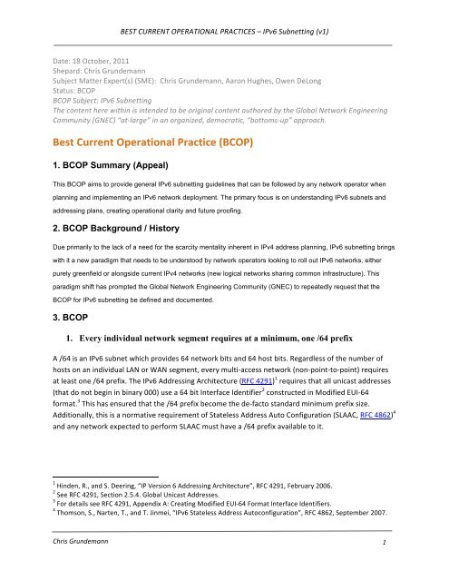
BEST CURRENT OPERATIONAL PRACTICES – <strong>IPv6</strong> <strong>Subnetting</strong> (v1) <br />
Date: 18 October, 2011 <br />
Shepard: Chris Grundemann <br />
Subject Matter Expert(s) (SME): Chris Grundemann, Aaron Hughes, Owen DeLong <br />
Status: <strong>BCOP</strong> <br />
<strong>BCOP</strong> Subject: <strong>IPv6</strong> <strong>Subnetting</strong> <br />
The content here within is intended to be original content authored by the Global Network Engineering <br />
Community (GNEC) “at-‐large” in an organized, democratic, “bottoms-‐up” approach. <br />
Best Current Operational Practice (<strong>BCOP</strong>) <br />
1. <strong>BCOP</strong> Summary (Appeal)<br />
This <strong>BCOP</strong> aims to provide general <strong>IPv6</strong> subnetting guidelines that can be followed by any network operator when<br />
planning and implementing an <strong>IPv6</strong> network deployment. The primary focus is on understanding <strong>IPv6</strong> subnets and<br />
addressing plans, creating operational clarity and future proofing.<br />
2. <strong>BCOP</strong> Background / History<br />
Due primarily to the lack of a need for the scarcity mentality inherent in IPv4 address planning, <strong>IPv6</strong> subnetting brings<br />
with it a new paradigm that needs to be understood by network operators looking to roll out <strong>IPv6</strong> networks, either<br />
purely greenfield or alongside current IPv4 networks (new logical networks sharing common infrastructure). This<br />
paradigm shift has prompted the Global Network Engineering Community (GNEC) to repeatedly request that the<br />
<strong>BCOP</strong> for <strong>IPv6</strong> subnetting be defined and documented.<br />
3. <strong>BCOP</strong><br />
1. Every individual network segment requires at a minimum, one /64 prefix<br />
A /64 is an <strong>IPv6</strong> subnet which provides 64 network bits and 64 host bits. Regardless of the number of <br />
hosts on an individual LAN or WAN segment, every multi-‐access network (non-‐point-‐to-‐point) requires <br />
at least one /64 prefix. The <strong>IPv6</strong> Addressing Architecture (RFC 4291) 1 requires that all unicast addresses <br />
(that do not begin in binary 000) use a 64 bit Interface Identifier 2 constructed in Modified EUI-‐64 <br />
format. 3 This has ensured that the /64 prefix become the de-‐facto standard minimum prefix size. <br />
Additionally, this is a normative requirement of Stateless Address Auto Configuration (SLAAC, RFC 4862) 4<br />
and any network expected to perform SLAAC must have a /64 prefix available to it. <br />
1 Hinden, R., and S. Deering, “IP Version 6 Addressing Architecture”, RFC 4291, February 2006. <br />
2 See RFC 4291, Section 2.5.4. Global Unicast Addresses. <br />
3 For details see RFC 4291, Appendix A: Creating Modified EUI-‐64 Format Interface Identifiers. <br />
4 Thomson, S., Narten, T., and T. Jinmei, “<strong>IPv6</strong> Stateless Address Autoconfiguration”, RFC 4862, September 2007. <br />
Chris Grundemann <br />
1
BEST CURRENT OPERATIONAL PRACTICES – <strong>IPv6</strong> <strong>Subnetting</strong> (v1) <br />
While there are scenarios where it may be possible, or even advisable, to avoid this requirement; these <br />
are considered corner cases and not the general best practice, with one notable exception: Point-‐to-point<br />
links, detailed below. <br />
2. Only subnet on nibble boundaries<br />
A nibble boundary is a network mask which aligns on a 4-‐bit boundary. Nibble boundaries should be <br />
used to provide more human-‐readable addressing. This improves operational efficiency and reduces <br />
mistaken configuration by making the individual prefixes more recognizable and easier to understand <br />
sequentially. This is illustrated with several examples in Figure 1 below. As you can see in this example, <br />
the nibble aligned prefixes count upwards in a very predictable and obvious manner, the non-‐nibble <br />
aligned prefixes provide a much less apparent and easy to predict pattern. The latter often results in a <br />
higher tendency towards potentially costly “fat finger” mistakes. <br />
Figure 1 -‐ Examples of Nibble and Non-‐Nibble Boundaries <br />
Note: Since the smallest subnet mask used for multi-‐access networks is a /64, simply counting down by 4 <br />
will give you the nibble boundary masks; 64, 60, 56, 52, 48, 44, etc. <br />
Large networks that may grow beyond their initial allocation, and thus require a subsequent allocation, may <br />
want to consider not rounding up to nibble boundaries initially. This is especially true for networks using <br />
non-‐ARIN space. <br />
Rounding up to the nearest nibble boundary represents an over subscription value of up to 16 times. <br />
Justification for additional allocations or assignments will require the demonstration of efficient utilization <br />
of the currently held space. Such a large over-‐sizing factor may result in some areas of the network having <br />
no space available while the overall utilization is too low to justify additional space. <br />
This is not an issue in the ARIN region where rounding up to nibble boundaries is specifically allowed for, and <br />
a network is considered out of space when that network does not have available space to replenish any <br />
Chris Grundemann <br />
2
BEST CURRENT OPERATIONAL PRACTICES – <strong>IPv6</strong> <strong>Subnetting</strong> (v1) <br />
single pool within the addressing hierarchy (regardless of the utilization in other pools). However, this policy <br />
is not yet currently supported in the other regions. As such, networks that are likely to require a subsequent <br />
allocation from RIRs other than ARIN may want to consider rounding up only to standard CIDR boundaries <br />
(powers of two). <br />
3. Implement a hierarchical addressing plan to allow for aggregation<br />
In a typical network, this equates to at least three levels of hierarchy; site, region and AS. A site can be a <br />
PoP, a building, a floor, or any other logical layer3 aggregation point within your network. In general, <br />
each site should receive one /48. <br />
Figure 2 -‐ Example 3-‐level Hierarchy <br />
In some cases, a network may need additional aggregation points and thus a deeper hierarchy. In an <br />
extremely large network, this could be, for example; department, floor, building, campus, region, AS. <br />
Another important consideration is that this large address space facilitates grouping types of usage <br />
within your address space (using common bit patterns for common uses). Grouping customer space <br />
(used by external parties), infrastructure space (interface addresses), internal space (used for the <br />
corporate network) critical internal space (RADIUS, TACACS, jump servers), etc., may make sense in your <br />
environment. Having a well-‐defined addressing plan that distinguishes between the various address <br />
usage types can simplify and reduce filter size. <br />
4. One /48 from each region should be reserved for infrastructure<br />
Reserve the first or last /48 from each region for infrastructure needs; interface numbering, loopback <br />
addresses, etc. <br />
a. Loopbacks should be allocated from the first /64<br />
Chris Grundemann <br />
3
BEST CURRENT OPERATIONAL PRACTICES – <strong>IPv6</strong> <strong>Subnetting</strong> (v1) <br />
The first (least specific, e.g. 2001:db8:100::/64 from 2001:db8:100::/48) /64 prefix of each region’s <br />
infrastructure /48 should be reserved for loopback addresses. Loopbacks are only required to have a <br />
/128 mask (a single address) and thus can be numbered sequentially from the reserved /64. <br />
Note well that <strong>IPv6</strong> addresses are represented in hexadecimal, not decimal, notation. This means that <br />
“a” comes after “9”, not “10”. Of course you can skip hex digits and give your addresses the appearance <br />
of decimal numbering, which may be useful e.g. when matching loopback addresses to “router number” <br />
(i.e. although ::9 and ::10 are not sequential, that does not necessarily preclude you from numbering <br />
that way). <br />
An alternative method is to allocate a full /64 for each loopback address, as described below for PtP <br />
links. This avoids violating RFC 4291’s Interface ID requirement and it can be said that it isn't necessary <br />
to save <strong>IPv6</strong> address space by using /128s on loopbacks. For example, out of a /48, if you reserved <br />
16,384 /64s for loopbacks, you would be left with an additional 49,152 /64 subnets for links. <br />
b. Point-to-point links should be allocated a /64 and configured with a /126 or<br />
/127<br />
Allocating an entire /64 to each PtP link provides much more human readable addresses (e.g. X::1 and <br />
X::2). However, despite the requirement for a 64bit Interface ID mentioned above, a /126 or /127 mask <br />
should be used when configuring the actual network gear to avoid the Ping Pong, Neighbor Cache <br />
Exhaustion, and other similar issues, as documented in section 5 of RFC 6164. 5<br />
Note well that there may be problems with using /127 prefix lengths in operation due to vendor <br />
implementation variance with regard to subnet-‐router anycast. 6 This issue is documented in RFC 3627, 7<br />
specifically in section 3. Thorough testing in your own network environment is highly encouraged before <br />
attempting to use /127 prefixes in production, particularly in multi-‐vendor scenarios with any <br />
requirement for interoperability. <br />
It is also worth noting that two addresses that are in the same /126 subnet will not be in the same /127 <br />
subnet, and vice versa. So /126 addressing might use X::1 and X::2, but with /127 subnets those would <br />
be in different networks, so you would have to use X:: and X::1, or X::2 and X::3. <br />
5. Sites/PoPs/locations and regions, etc. should be laid out such that within each level<br />
of the hierarchy, each subnet prefix is of equal size<br />
Within your hierarchical addressing plan, as described above, you should ensure that each unit at an <br />
equal level receives an equal sized prefix (i.e. each site should receive the same prefix size (e.g. /48) and <br />
each region should receive the same prefix size (e.g. /36)). This is once again a valuable aid in simplifying <br />
5 Kohno, M., Nitzan, B., Bush, R., Matsuzaki, Y., Colitti, L., and T. Narten, “Using 127-‐Bit <strong>IPv6</strong> Prefixes on Inter-‐<br />
Router Links”, RFC 6164, April 2011. <br />
6 See RFC 4291, Section 2.6.1. Required Anycast Address. <br />
7 P. Savola, “Use of /127 Prefix Length Between Routers Considered Harmful”, RFC 3627, September 2003. <br />
Chris Grundemann <br />
4
BEST CURRENT OPERATIONAL PRACTICES – <strong>IPv6</strong> <strong>Subnetting</strong> (v1) <br />
network configuration, operation, and troubleshooting. The vast increase in address space available to <br />
us with <strong>IPv6</strong> allows for the creation of a homogenous, and therefor much more predictable, addressing <br />
plan. <br />
The best way to ensure this is to plan based on the largest unit at each level. For example: <br />
1. Take the largest site in your network, project its 5 year growth needs and allocate the required <br />
prefix for each of your sites. <br />
2. Then look at your largest region, and allocate a prefix adequate to serve its needs for each of <br />
your regions. <br />
Below are two examples to further illustrate this practice. <br />
In some networks there may be individual regions or sites that are so disparate in size or growth rate that <br />
this practice would result in very low (
BEST CURRENT OPERATIONAL PRACTICES – <strong>IPv6</strong> <strong>Subnetting</strong> (v1) <br />
needing to add additional resources. Remember that within each campus, one /48 is reserved for <br />
infrastructure. <br />
Figure 4 illustrates an example of a residential internet Service Provider (ISP) network. In this example, <br />
the operator has chosen to allocate a /48 prefix for each Multiple Dwelling Unit (MDU) but to allocate a <br />
smaller /56 prefix for individual Single Family Homes (SFH). <br />
This is an example for demonstrative purposes only. Individual operators will need to determine their own <br />
prefix size preference for serving customers (internal or external). The SMEs of this <strong>BCOP</strong> highly recommend <br />
a /48 for any site that requires more than one subnet and that a site be defined as an individual customer in <br />
residential networks. <br />
Each of the ISPs Points of Presence (PoP) serves a different number of MDUs and SFHs. For example, the <br />
area served by PoP 3 contains 50 MDUs and 150,000 SFHs. Adding up the direct need we can see that to <br />
allocate a /48 to each of the 50 MDUs, this provider needs at least a /42. To allocate a /56 to each of the <br />
150,000 SFHs, they need at minimum a /38. This aggregate demand, rounded up to a nibble boundary, <br />
determines the need for a /36 to serve this PoP (don’t forget to add the /48 for infrastructure). Since <br />
none of the other 3 PoPs require more than a /36, that was chosen as the standard PoP prefix length. <br />
Since there are only 4 PoPs in this ISPs network, they set their AS allocation at the next nibble boundary; <br />
a /32. <br />
Chris Grundemann <br />
6
BEST CURRENT OPERATIONAL PRACTICES – <strong>IPv6</strong> <strong>Subnetting</strong> (v1) <br />
Figure 4 -‐ Example residential ISP network <br />
This same logic holds true no matter neither the size of your network nor the levels of hierarchy. You <br />
should always determine aggregate need of your largest site or region (including a /48 for <br />
infrastructure), round that up to a nibble-‐aligned prefix, and allocate an equal prefix to all <br />
sites/regions/etc. Then you repeat the exercise for each level of hierarchy within your network. <br />
a. Each “site” should likewise have an equalized internal hierarchy<br />
Within a single site, a similar hierarchy should be implemented. In this case, each individual network <br />
segment requires a /64 and departments, rooms, floors, etc. can occupy the next level up with a /60, <br />
/56, or /52 depending on whether depth or breadth better fits the network’s needs.<br />
Chris Grundemann <br />
7
BEST CURRENT OPERATIONAL PRACTICES – <strong>IPv6</strong> <strong>Subnetting</strong> (v1) <br />
4. <strong>BCOP</strong> Conclusion<br />
1. Every individual network segment requires at a minimum, one /64 prefix <br />
2. Only subnet on nibble boundaries <br />
3. Implement a hierarchical addressing plan to allow for aggregation <br />
a. Each individual site should be allocated a /48 prefix <br />
4. One /48 from each region should be reserved for infrastructure <br />
a. Loopbacks should be allocated from the top /64 <br />
b. Point-‐to-‐point links should be allocated a /64 and configured with a <br />
/126 or /127 <br />
5. Sites/PoPs/locations and regions, etc. should be laid out such that within <br />
each level of the hierarchy, each subnet prefix is of equal size <br />
a. Each “site” should likewise have an equalized internal hierarchy <br />
Chris Grundemann <br />
8