Industrial seal self study guide - SKF.com
Industrial seal self study guide - SKF.com
Industrial seal self study guide - SKF.com

Create successful ePaper yourself
Turn your PDF publications into a flip-book with our unique Google optimized e-Paper software.
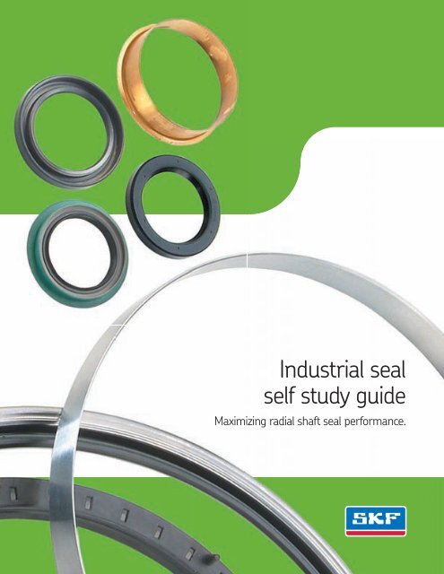
<strong>Industrial</strong> <strong>seal</strong><br />
<strong>self</strong> <strong>study</strong> <strong>guide</strong><br />
Maximizing radial shaft <strong>seal</strong> performance.
TABLE OF CONTENTS<br />
Chapter 1<br />
Introduction. . . . . . . . . . . . . . . . . . . . . . . . 2-4<br />
Basic Seal Types . . . . . . . . . . . . . . . . . 5-9<br />
Chapter 2 Review. . . . . . . . . . . . . . . . . 10-11<br />
Seal Design Groups . . . . . . . . . . . . . 12-28<br />
Chapter 3 Review. . . . . . . . . . . . . . . . . 29-31<br />
Seal Applications . . . . . . . . . . . . . . . 32-43<br />
Chapter 4 Review. . . . . . . . . . . . . . . . . 44-45<br />
Seal Selection . . . . . . . . . . . . . . . . . 46-50<br />
Chapter 5 Review. . . . . . . . . . . . . . . . . 51-52<br />
Wear Sleeves . . . . . . . . . . . . . . . . . 53-57<br />
Chapter 6 Review. . . . . . . . . . . . . . . . . 58-59<br />
Shaft and Bore Conditions . . . . . . . 60-64<br />
Chapter 7 Review. . . . . . . . . . . . . . . . . 65-66<br />
Installation . . . . . . . . . . . . . . . . . . . 67-75<br />
Chapter 8 Review. . . . . . . . . . . . . . . . . 76-77<br />
Troubleshooting . . . . . . . . . . . . . . . 78-84<br />
Chapter 9 Review. . . . . . . . . . . . . . . . . 85-86<br />
Glossary of Seal Terms . . . . . . . . . . 87-93<br />
Final Review . . . . . . . . . . . . . . . . . 94-107<br />
1
CHAPTER 1—<br />
INTRODUCTION<br />
This book, produced for use by distributors and end-users, should<br />
prove of practical value to engineers, industrial designers, maintenance<br />
superintendents and anyone who can benefit from a thorough<br />
understanding of <strong>seal</strong>s.<br />
It will explain:<br />
• What types of <strong>seal</strong>s are available<br />
• How to select the best <strong>seal</strong> for any given application<br />
• How to improve performance with proper installation<br />
• How to repair <strong>seal</strong>-worn shaft surfaces<br />
• How to spot and correct <strong>seal</strong> problems economically<br />
How to Use this Study Guide<br />
This <strong>self</strong>-<strong>study</strong> <strong>guide</strong> is designed to increase performance productivity.<br />
Each chapter consists of a logical organization of material, technical<br />
diagrams and a short quiz to help you retain what you <strong>study</strong>.<br />
Carefully read the text portion of each chapter. Make notes or<br />
underline if you wish; this can help you remember what you’ve read.<br />
This material is designed for the individual’s own learning pace. At the<br />
end of the program, you will have learned the same information and<br />
should retain it as well as any other “student.”<br />
The chapter quizzes are an important phase of <strong>self</strong>-<strong>study</strong> learning<br />
since they are intended to reinforce the material covered. The quiz<br />
questions are straightforward multiple choice and true–false. There<br />
are no “trick questions.” Your answers can easily be checked by<br />
referring to the material presented in the chapter.<br />
Complete each review in order before going on to the next chapter.<br />
If you are not sure of an answer to a question, check back in the<br />
chapter and review that portion again.<br />
If you follow this procedure through all nine chapters, you should<br />
gain a thorough understanding of shaft <strong>seal</strong>s.<br />
You will be able to test your knowledge through an overall “Final<br />
Review” at the end of the book. This is a final check for the reader.<br />
A “Certificate of Merit” to those who successfully pass the final review<br />
with a minimum score of 85% will be issued. Instructions for obtaining<br />
a certificate are at the end of this book.<br />
2
1<br />
Brief History of the Shaft Seal<br />
<strong>SKF</strong> Sealing Solutions invented and patented the first integrated,<br />
<strong>self</strong>-contained shaft <strong>seal</strong> in 1928 (fig. 1a). It was designed to hold<br />
grease in automobile wheel hubs and help lubricate the wheel bearing.<br />
In the mid 1930’s, <strong>SKF</strong> pioneered the development of custom<br />
formulating, <strong>com</strong>pounding and molding of elastomers (synthetic<br />
rubber) to develop higher performance materials. This led to other<br />
innovations in manufacturing processes, new <strong>seal</strong>ing techniques to<br />
handle more demanding automotive and industrial applications<br />
and the <strong>com</strong>pounding and molding of various elastomer <strong>seal</strong>s to<br />
improve consistency and quality.<br />
Today, <strong>SKF</strong> is the world’s leading supplier of fluid <strong>seal</strong>ing devices for<br />
the truck, automotive, farm equipment, aircraft, heavy machinery<br />
and machine tool industries. <strong>SKF</strong> also supplies <strong>seal</strong>s for aerospace<br />
missiles, earthmoving equipment, appliances, and a wide variety of<br />
pumps, hydraulic systems, motors and sub-assemblies.<br />
A <strong>com</strong>pany-wide <strong>com</strong>mitment to quality earned <strong>SKF</strong> Sealing<br />
Solutions significant certifications including TS16949 in December<br />
2002 and ISO 9001:2000 in May 1999.<br />
<strong>SKF</strong> can supply more than 200 types of <strong>seal</strong>s, over 3,000 stock<br />
sizes, and over 10,000 cataloged variations. That includes <strong>seal</strong>s in<br />
both inch and metric sizes, metal and rubber O.D.’s in both bonded<br />
and assembled designs, with single or double lip elements and with<br />
or without springs or inner cases (fig. 1b).<br />
<strong>SKF</strong> <strong>seal</strong>ing products fit shaft diameters from . 110” to over 180”.<br />
They fit metric shaft diameters from 3mm to over 4572mm. All are<br />
fashioned from an ever-growing spectrum of <strong>seal</strong>ing elements<br />
and materials including LongLife fluoroelastomer lip materials.*<br />
That, plus ongoing development of new materials and processes,<br />
will enable <strong>SKF</strong> to meet tomorrow’s expectations.<br />
<strong>SKF</strong> invented the shaft<br />
<strong>seal</strong> in 1928 (fig. 1a).<br />
Over 2 types of <strong>seal</strong>s are now<br />
available from <strong>SKF</strong> (fig. 1b).<br />
*LongLife is a registered trademark of <strong>SKF</strong><br />
3
INTRODUCTION (cont.)<br />
The Total Bearing and Seal Service Concept<br />
When bearings fail, they can bring equipment to an unscheduled halt.<br />
Every hour of downtime due to premature bearing failure can result in<br />
costly lost production, especially in capital intensive manufacturing.<br />
The majority of bearings outlive the machinery or equipment in<br />
which they are installed. Of the bearings that do fail, only 1/3 fail due<br />
to normal fatigue. Over half of bearing failures result from lubrication<br />
or contamination problems—both of which can be related to the <strong>seal</strong>ing<br />
arrangement. Seals are vital to all bearing applications and are a critical<br />
<strong>com</strong>ponent in an integrated systems approach to Trouble-Free<br />
Operation.<br />
Product Quality<br />
The <strong>SKF</strong> goal is to provide every bearing user with long, trouble-free<br />
operation. Our substantial investment in research and development has<br />
resulted in the production of bearings and <strong>seal</strong>s of the highest quality.<br />
However, quality alone cannot guarantee trouble-free operation.<br />
Other factors affect the life span of every bearing, including:<br />
Operating Environment<br />
Machinery must be kept in peak operating condition. The bearings should<br />
be properly aligned and protected from extreme temperatures and properly<br />
<strong>seal</strong>ed from moisture and contaminants. The <strong>seal</strong>s must also retain the<br />
lubricant to assure a proper oil film.<br />
Proper Installation<br />
Knowledge of the proper installation techniques and tools is required<br />
to ensure that the bearings and <strong>seal</strong>s are not damaged.<br />
Proper Maintenance<br />
Following lubrication and maintenance schedules and monitoring bearing<br />
operating conditions are also important in maximizing bearing life.<br />
Trouble-Free Operation<br />
<strong>SKF</strong> is <strong>com</strong>mitted to the proper servicing and maintenance of the<br />
bearing/<strong>seal</strong>ing arrangement. The Trouble-Free Operation Concept<br />
minimizes the risk of bearing downtime and ensures that your bearings<br />
achieve their full potential. A full line of products and services is available<br />
from <strong>SKF</strong> to make installation and maintenance easy to perform.<br />
The Trouble-Free Operation Concept meets customer demands for<br />
long bearing life and cost-effective operation.<br />
4
Chapter 2—Basic Seal Types<br />
Seal Functions<br />
Whenever a shaft rotates, it needs a bearing arrangement for smooth,<br />
effective operation. Wherever there’s a bearing, you’ll find a <strong>seal</strong> helping<br />
it to reach its maximum service life and reliability. In simplest terms<br />
a shaft <strong>seal</strong> is a barrier.<br />
2<br />
This barrier has four functions:<br />
• Retain lubricants and/or liquids<br />
• Exclude dirt/contaminants<br />
• Separate fluids<br />
• Confine pressure<br />
When a <strong>seal</strong> performs these functions properly, it protects the bearing<br />
from harmful contaminants while retaining a clean lubricant supply,<br />
resulting in lengthened bearing service life and reliability. The bearings<br />
do their job better, cleanliness of production and process materials is<br />
maintained, lubricant is saved and machinery downtime is reduced.<br />
An integrated bearing/<strong>seal</strong> system approach is the best way to achieve<br />
trouble-free operation (fig. 2a).<br />
Sealing takes place as lube is<br />
retained and outside contaminants<br />
are excluded (fig. 2a).<br />
Seals handle a broad range of media, from light oil to heavy grease to<br />
hot turbine gases. Electric motors and gear reduction units are some<br />
of the more <strong>com</strong>mon applications, however there are extremes requiring<br />
very special solutions.<br />
For example, <strong>seal</strong>s protect the high speed turbine pump in a rocket<br />
that accelerates from 0 to 12,000 rpm in one-fourth of a second.<br />
Other types of <strong>seal</strong>s protect the drive unit in a track type earth mover,<br />
operating at only 15 to 30 rpm.<br />
Static Seals<br />
The function of static <strong>seal</strong>s is to create barriers between relatively<br />
non-moving surfaces. Typical “static” applications of <strong>seal</strong>s are<br />
valve-cover gaskets, cylinder covers, packings of many kinds, and<br />
o-rings used in stationary situations. The gasket lining a refrigerator<br />
door used to <strong>seal</strong> the inside chilled air from the outside ambient<br />
temperature is a classic static <strong>seal</strong> application. “Static” simply means<br />
that no relative motion takes place in the performance of the <strong>seal</strong>ing<br />
function. The <strong>seal</strong>ing devices for such applications are often tailored<br />
from o-rings. Typical sectional views of static <strong>seal</strong> applications are<br />
shown in figure 2b.<br />
Sectional views of typical<br />
static or non-moving <strong>seal</strong><br />
applications (fig. 2b).<br />
5
BASIC SEAL TYPES (cont.)<br />
A<br />
As a shaft rotates in a stationary<br />
housing, a CRW1 dynamic radial<br />
<strong>seal</strong> both retains lubricant and<br />
excludes contaminants (fig. 2c).<br />
B<br />
Axial mechanical <strong>seal</strong>s create an<br />
interface along the shaft plane<br />
between matched <strong>com</strong>ponents.<br />
Usually, one contact face is stationary<br />
while the other rotates with the shaft<br />
(fig. 2d).<br />
At the “interface” point, a thin film<br />
of lubricant separates <strong>seal</strong>ing surfaces<br />
(fig. 2e).<br />
Dynamic “Radial” Seals<br />
A dynamic radial <strong>seal</strong> creates a barrier or interface between surfaces<br />
in relative motion. For radial lip type <strong>seal</strong>s, the interface is where the<br />
<strong>seal</strong> touches the shaft. Sealing is ac<strong>com</strong>plished by two surfaces making<br />
contact radially, one usually stationary while the other rotates.<br />
An example of a radial <strong>seal</strong> is shown in figure 2c. As the shaft rotates<br />
in a stationary housing, a CRW1 <strong>seal</strong> both retains lubricant and<br />
excludes contaminants. Typical radial <strong>seal</strong> applications include<br />
gearboxes, drives, motors, pumps and speed reducers.<br />
Axial Mechanical Seals<br />
Axial mechanical <strong>seal</strong>s are face type <strong>seal</strong>s which create an axial<br />
<strong>seal</strong> interface between matched, radially mounted <strong>com</strong>ponents. In<br />
operation, one contact face is usually stationary in the housing while<br />
the other moves with the shaft. Sealing pressure is applied in the<br />
axial direction through a spring mechanism. The spring force keeps<br />
the surfaces together.<br />
Axial mechanical <strong>seal</strong>s are generally used where pressure and/or<br />
surface speeds exceed the capabilities of radial shaft <strong>seal</strong>s. Typical<br />
applications are water pumps and most types of pumps used in<br />
chemical processing plants or refineries. Figure 2d is a view of<br />
such an installation.<br />
Other types of axial <strong>seal</strong>s are “non-mechanical” ones, such as V-Rings.<br />
Seal Interface<br />
“Interface” is the point of contact between <strong>seal</strong>ing surfaces (fig. 2e). But<br />
they do not really “contact” at that point, they are separated by a film<br />
of lubricant as thin as 0.00001 in.—a hundred thousandths of an inch.<br />
In metrics, that is 0.25 microns.<br />
The lubricant film prevents rapid wear of the <strong>seal</strong> lip and/or the shaft<br />
surface. But interface tolerances must be precise to keep the lubricant<br />
from leaking. Uncontrolled conditions of run-out must be prevented.<br />
Any misalignment or eccentricity of interfacing surfaces which exceed<br />
acceptable tolerances must be corrected.<br />
6
Factors Affecting Seal Selection<br />
Every <strong>seal</strong> application has a unique set of characteristics that must be<br />
analyzed in order to specify the exact style and type of <strong>seal</strong> (fig. 2f).<br />
Selecting the right <strong>seal</strong> depends on the basic parameters of the<br />
application, including:<br />
• Shaft speed<br />
• Fluid <strong>com</strong>patibility<br />
• Primary <strong>seal</strong> function (retention or exclusion)<br />
• Operating pressure<br />
• Maximum temperature<br />
2<br />
How to Measure Speed<br />
Surface speed at the point of contact between the <strong>seal</strong> and the<br />
shaft (fpm: feet per minute, or mpm: meters per minute) is generally a<br />
better indicator of <strong>seal</strong> performance than revolutions per minute (rpm).<br />
To convert rpm to fpm, use the following formula or refer to the<br />
<strong>SKF</strong> Handbook of Seals.<br />
.262 x rpm x shaft diameter = fpm (feet per minute)<br />
To convert rpm to mpm, use the following formula or refer to the<br />
<strong>SKF</strong> Handbook of Seals.<br />
3.142 x .001 x rpm x shaft dia. (mm) = mpm (meters per minute)<br />
or<br />
3.142 x .001 x rpm x shaft dia. (mm) / 60 = ms (meters per second)<br />
Pressure<br />
The more pressure applied to a <strong>seal</strong>, the greater the friction and heat.<br />
That means faster wear and shorter <strong>seal</strong> life. Most <strong>SKF</strong> bonded oil <strong>seal</strong>s handle<br />
pressure up to 10 psi (.07 MPa), at speeds from 0 to 1000 fpm (5.08 m/s).<br />
For <strong>com</strong>plete pressure ratings, consult the <strong>SKF</strong> Handbook of Seals.<br />
Temperature/Fluid Compatibility<br />
Another consideration affecting <strong>seal</strong> selection is temperature and<br />
fluid <strong>com</strong>patibility. Handbook listings are given in “continuous” ratings—<br />
the relatively constant ambient temperature next to the <strong>seal</strong>, or the<br />
temperature of the lubricant it retains.<br />
When operating conditions are under O˚F or above 200˚F<br />
(-17 -93˚C), , the range re<strong>com</strong>mended in the Handbook must be<br />
considered in selecting the type of <strong>seal</strong>ing material.<br />
Factors such as shaft<br />
speed, operating pressure,<br />
internal and external<br />
temperature, all affect<br />
proper <strong>seal</strong> selection (fig. 2f).<br />
7
BASIC SEAL TYPES (cont.)<br />
As was earlier stated, <strong>SKF</strong>’s standard nitrite <strong>com</strong>pound provides good<br />
service in most <strong>seal</strong>ing applications from -40˚F to 250˚F (-40˚C to<br />
121˚C). However, silicone, polyacrylate, Longlife or PTFE may be more<br />
suitable for and should be considered for temperatures outside this<br />
range.<br />
For more information on the temperature <strong>com</strong>patibility and abrasion<br />
resistance of various <strong>seal</strong> lip materials, turn to Chapter 4.<br />
When a <strong>seal</strong>’s basic<br />
function is to retain,<br />
face the <strong>seal</strong> lip toward<br />
lubricant (fig. 2g).<br />
When the <strong>seal</strong>’s basic function<br />
is to exclude, face the <strong>seal</strong> lip<br />
toward contaminants (fig. 2h).<br />
For retention/exclusion applications,<br />
a <strong>com</strong>bination of <strong>seal</strong>s in a unitized<br />
assembly can be the best solution<br />
(fig. 2i).<br />
Most applications for shaft <strong>seal</strong>s involve the need to retain or separate<br />
lubricants from some form of external contaminant or abrasion. But<br />
many times it must be determined which is more important, retention<br />
of lubricant or exclusion of foreign matter.<br />
Retention<br />
When the <strong>seal</strong>’s basic function is to retain lubrication, pressure, or both,<br />
the lip of the <strong>seal</strong> (generally the spring side) must face toward the<br />
lubricant or the pressure being retained and generally be spring<br />
assisted (fig. 2g).<br />
Exclusion<br />
Most bearings fail from the entrance of foreign material and from the<br />
loss or degradation of lubricant. Dirt, abrasives, water and other liquids<br />
can interfere with the film of lubricant required to support the moving<br />
parts of a bearing in a <strong>seal</strong>ed system. Reliable excluders generally<br />
include V-Rings and non-spring loaded <strong>seal</strong>s.<br />
Therefore, it’s vitally important for the <strong>seal</strong> to keep those materials<br />
from entering the bearing cavity. When the <strong>seal</strong>’s basic function is to<br />
exclude, the lip of the <strong>seal</strong> should face toward the contaminants<br />
instead of toward the bearing (fig. 2h). However in this case, only<br />
grease lubrication should be used since oil loss could be excessive.<br />
Retention/Exclusion<br />
Some extreme applications require the <strong>seal</strong> to perform both the<br />
retention and exclusion functions at the same time. For example, the<br />
<strong>seal</strong> may need to confine a lubricant while excluding dust or cleaning<br />
solutions. In this case, a special type of protection is necessary either<br />
a <strong>com</strong>bination of <strong>seal</strong>s back-to-back or dual <strong>seal</strong>ing elements within<br />
one unitized assembly (fig. 2i).<br />
8
Summary<br />
There are many factors involved in selecting <strong>seal</strong>s. To avoid confusion,<br />
the <strong>SKF</strong> Handbook of Seals contains a “Re<strong>com</strong>mended Operating<br />
Conditions” selection chart to assure a correct <strong>seal</strong> choice. All of the<br />
selection factors are grouped together along with re<strong>com</strong>mendations<br />
about the type of <strong>seal</strong> to use in almost every application.<br />
2<br />
Seal Components<br />
There are five basic <strong>seal</strong> <strong>com</strong>ponents (fig. 2j), each performing<br />
a particular function. They include:<br />
• Outer Shell (Case). The outer, cup-shaped, rigid structure<br />
(metal or rubber over a metal case) of the lip <strong>seal</strong> assembly.<br />
Primarily used for holding the <strong>seal</strong> in place. The lip is generally<br />
bonded to the outer shell. (A)<br />
• Inner Shell (Case). A rigid cup-shaped <strong>com</strong>ponent of a <strong>seal</strong><br />
assembly, which is placed inside the outer <strong>seal</strong> case. Reinforces<br />
the outer shell. Can also function as a shield or spring retainer<br />
device. (B)<br />
• Primary Lip (Head Section). The flexible elastomeric <strong>com</strong>ponent<br />
of a lip <strong>seal</strong> which contacts the rotating surface. Normally points<br />
toward the most important <strong>seal</strong>ing job, either retaining or<br />
excluding. (C, D)<br />
• Secondary Lip (Auxiliary Lip). A short, non-spring loaded lip which<br />
is located at the outside <strong>seal</strong> face of a radial lip <strong>seal</strong>. Used to<br />
exclude contaminants. Used only in dual lip designs. (E)<br />
• Garter Spring. A coiled wire spring with its ends connected.<br />
It provides a controlled radial load for the lip/shaft interface. (F)<br />
B<br />
D<br />
F<br />
Each of the <strong>seal</strong>’s basic<br />
<strong>com</strong>ponents contribute to its<br />
function (fig. 2j).<br />
A<br />
C<br />
E<br />
9
CHAPTER 2 REVIEW<br />
To take this test, simply place a card or sheet of paper under the first question. After<br />
you’ve read it (and answered it to your<strong>self</strong>) slide the paper down below the next question.<br />
The correct answer to the first problem will appear directly to the right of the new<br />
question. Be sure not to skip any questions.<br />
1. A shaft <strong>seal</strong> is a barrier designed to retain lubricants and _________________.<br />
❑ a. confine pressure<br />
❑ b. exclude dirt<br />
❑ c. separate fluids<br />
❑ d. all of the above<br />
2 The _________________ of a <strong>seal</strong> is a cup-shaped rigid structure that<br />
protects the head of the <strong>seal</strong>ing element.<br />
❑ a. primary lip<br />
❑ b. outer shell (case)<br />
❑ c. inner shell (case)<br />
❑ d. garter spring<br />
3. Typical radial <strong>seal</strong> applications include _________________.<br />
❑ a. gearboxes<br />
❑ b. motors<br />
❑ c. pumps<br />
❑ d. all of the above<br />
4. Selecting the right <strong>seal</strong> depends on application parameters, including<br />
_________________.<br />
❑ a. shaft speed<br />
❑ b. fluid <strong>com</strong>patibility<br />
❑ c. operating pressure<br />
❑ d. all of the above<br />
5. When the <strong>seal</strong>’s basic function is to retain, the lip of the <strong>seal</strong> should<br />
face away from the lubricant or pressure being retained.<br />
❑ True ❑ False<br />
6. More bearings fail from the entrance of foreign material than<br />
from loss of lubricant.<br />
❑ True ❑ False<br />
1. D<br />
2. B<br />
3. D<br />
4. D<br />
5. F<br />
6. T<br />
10
7. The function of static <strong>seal</strong>s is to create barriers between relatively<br />
non-moving surfaces.<br />
❑ True ❑ False<br />
8. Axial mechanical <strong>seal</strong>s are generally used where pressure and/or surface<br />
speeds are more than radial shaft <strong>seal</strong>s can handle.<br />
❑ True ❑ False<br />
9. Seal “interfaces” is the point of contact between <strong>seal</strong>ing surfaces, but do not<br />
actually contact because they are separated by a film of lubricant.<br />
❑ True ❑ False<br />
10. Revolutions per minute (rpm) is generally a better indication<br />
of <strong>seal</strong> performance than feet per minute (fpm).<br />
❑ True ❑ False<br />
11. The more pressure you apply to a <strong>seal</strong>, the greater the frictional heat<br />
and faster the shaft wear.<br />
❑ True ❑ False<br />
12. Sealing lips of <strong>SKF</strong>’s standard nitrile <strong>com</strong>pound are correct for all applications.<br />
❑ True ❑ False<br />
13. Reliable exclusion <strong>seal</strong>s include V-Rings and non-spring-loaded <strong>seal</strong>s.<br />
❑ True ❑ False<br />
14. Retention/exclusion applications, sometimes require a <strong>com</strong>bination of<br />
<strong>seal</strong>s in one assembly.<br />
❑ True ❑ False<br />
15. The <strong>seal</strong>ing lip is generally bonded to the <strong>seal</strong>’s inner shell.<br />
❑ True ❑ False<br />
7. T<br />
8. T<br />
9. T<br />
10. F<br />
11. T<br />
12. F<br />
13. T<br />
14. T<br />
15. F<br />
2<br />
11
HM14<br />
<strong>SKF</strong>’s non-spring loaded designs (fig. 3a).<br />
HDW1 CRW1 CRWA5<br />
CRWA1<br />
CRWHA1<br />
HM21<br />
FF G HD<br />
TL<br />
HMA<br />
HMS4<br />
<strong>SKF</strong>’s standard spring-loaded<br />
designs are typically used to retain<br />
oil and/or exclude dirt in higher<br />
shaft speed applications (fig. 3b).<br />
CHAPTER 3—<br />
SEAL DESIGN GROUPS<br />
Basic Design Groups<br />
Seals with similar functional abilities are categorized into design<br />
groups. Note that design codes are unique to each manufacturer,<br />
and the ones listed below are codes used by <strong>SKF</strong>.<br />
Non-Spring Loaded Seals<br />
These <strong>seal</strong> designs are typically used for grease retention or dirt<br />
exclusion in slower shaft speed applications.<br />
The <strong>seal</strong>s illustrated in fig. 3a, HM14 and HM21, are <strong>SKF</strong>’s standard<br />
designs. Agricultural equipment and quarry conveyor systems are<br />
typical uses. They can also be used as light-duty rod wipers. Other<br />
designs include FF, G, HD, HMA and TL. The heavy-duty TL <strong>seal</strong> is<br />
designed for severe conditions such as disc harrows. For maximum<br />
dirt exclusion, they should be installed with the lip facing outward.<br />
Non-spring loaded <strong>seal</strong>s are not intended for lube oil retention.<br />
Non-spring loaded <strong>seal</strong>s, especially the HM design, are generally<br />
less expensive than spring-loaded versions, and generally cost much<br />
less than the assembled <strong>seal</strong>s they replace. They also provide a good<br />
level of performance when <strong>seal</strong>ing grease.<br />
Spring-Loaded Seals<br />
These <strong>seal</strong> designs are typically used to retain oil and/or exclude<br />
dirt in higher shaft speed applications (fig. 3b). <strong>SKF</strong>’s standard designs<br />
include: single lip, dual-lips, and single and double shell designs.<br />
The dual-lip design features a non-interference auxiliary lip for added<br />
exclusion protection without the heat build-up associated by traditional<br />
dual-lip designs. Typical applications include gearboxes, speed reducers,<br />
transmissions, motors and drive systems. CRW5 and CRWA5 types<br />
are designed for high pressure applications, up to 90 psi (.62 MPa).<br />
For maximum dirt exclusion, they should be installed with the lip facing<br />
outward. While this works well with grease, be aware of potentially<br />
high levels of oil leakage. The large diameter <strong>seal</strong> HDW1 type is<br />
designed for severe conditions.<br />
Spring-loaded <strong>seal</strong>s provide longer, more consistent service life<br />
in radial applications than non-spring loaded designs, and better<br />
<strong>seal</strong>ability over a wide range of conditions. They also perform<br />
exceptionally well in applications where there is shaft run-out<br />
and shaft-to-bore misalignment.<br />
12
Case Construction<br />
Seal cases are constructed with either metal or rubber outer<br />
diameters. The reasons for these different constructions—their features<br />
and benefits—are as follows:<br />
Metal O.D.<br />
Metal O.D. <strong>seal</strong>s feature a metal outer shell or case (fig. 3c). They are<br />
also available with an inner metal shell. The double metal shell provides<br />
torsional stiffness and assists in installation, especially where the<br />
assembly of the shaft is against the lip, or for “hammer” assembly<br />
of larger <strong>seal</strong>s.<br />
Dual-lip versions of metal O.D. <strong>seal</strong>s are available in many selected<br />
sizes.<br />
Applications for metal O.D. <strong>seal</strong>s include engines, drive axles,<br />
transmissions, pumps, electric motors and speed reducers. Overall,<br />
the metal-clad CRW <strong>seal</strong>s are re<strong>com</strong>mended over the more basic<br />
HMS <strong>seal</strong>s for most applications.<br />
Metal O.D. <strong>seal</strong>s perform well as economical, general-purpose designs<br />
and provide an exceptionally wide application range.<br />
Rubber O.D.<br />
Rubber O.D. <strong>seal</strong>s feature rubber molded around a steel stamping<br />
(fig. 3d).<br />
They are generally required for split housings and light alloys that are<br />
subject to thermal expansion or gaseous media.<br />
Rubber O.D. <strong>seal</strong>s can withstand reasonable abuse during installation,<br />
and can be inserted in imperfect or rough bores. Their construction<br />
provides limited additional rust resistance. Dual lip versions are<br />
available for many size <strong>com</strong>binations.<br />
CRW1<br />
CRW1 features a metal outer<br />
shell or case (fig. 3c).<br />
HMS5 features rubber<br />
molded around a steel<br />
stamping (fig 3d).<br />
3<br />
13
SEAL DESIGN GROUPS (cont.)<br />
Hydrodynamic Seals<br />
One of the most significant developments in <strong>seal</strong>ing technology<br />
occurred in the 1950’s with the introduction of hydrodynamic <strong>seal</strong>s.<br />
Hydrodynamic <strong>seal</strong>s have molded projections added to the <strong>seal</strong> lip<br />
which enables the <strong>seal</strong> to pump oil into the oil pump, improving<br />
lubricant retention.<br />
Standard hydrodynamic <strong>seal</strong> designs<br />
feature helical ribs, parabolic ribs or<br />
triangular pads (fig. 3e).<br />
There are a variety of molded projections used in hydrodynamic<br />
<strong>seal</strong>s. Standard designs have a series of helical ribs, parabolic<br />
triangular pads molded to the lip (fig. 3e). However, these designs<br />
are not without their problems. As dirt builds up against the <strong>seal</strong> lip,<br />
the lip wears, eliminating the hydrodynamic projections. They can also<br />
be<strong>com</strong>e clogged with carbon or dirt. Some hydrodynamic designs are<br />
uni-directional, and can actually pump lubricant out if installed incorrectly.<br />
<strong>SKF</strong> developed a new type of hydrodynamic <strong>seal</strong> in the early 1970’s.<br />
Called “Wave<strong>seal</strong>”, this design features a <strong>seal</strong>ing lip molded with a<br />
sinewave pattern. This traces a wavy path over the surface of the<br />
rotating shaft.<br />
Low Angle<br />
Steep Angle<br />
Scraper<br />
Wave<strong>seal</strong><br />
In technical terms, the <strong>SKF</strong> Wave<strong>seal</strong> is a smooth lip,<br />
bi-rotational hydrodynamic, molded radial lip <strong>seal</strong>. More simply, it is a<br />
shaft <strong>seal</strong> that pumps lubricant back into the sump while <strong>seal</strong>ing out<br />
contaminants no matter which way the shaft is turning.<br />
Low Angle<br />
Permits Oil<br />
To Slide<br />
Under Lip<br />
Steep Angle<br />
Scrapes Oil<br />
Inward<br />
Shaft<br />
Rotation<br />
The Wave<strong>seal</strong> by <strong>SKF</strong><br />
• Offers longer, more dependable performance and service life than<br />
conventional trimmed lip <strong>seal</strong>s and other hydrodynamic designs.<br />
• Has almost universal applications<br />
• Is the first standard line of shaft <strong>seal</strong>s incorporating hydrodynamics<br />
Static<br />
Contact<br />
Path<br />
Air Side<br />
Oil Particles<br />
Dynamic<br />
Contact<br />
Path<br />
Oil Side<br />
The <strong>SKF</strong> Wave<strong>seal</strong> touches the shaft<br />
in wide ‘sine’ or wave pattern. Due to<br />
this unique design, contact pressure<br />
and grooving are minimized, heat<br />
generation and friction are reduced.<br />
Lubricant is pumped back to the<br />
bearing while dirt is pushed away<br />
from the lip/shaft interface (fig. 3f).<br />
How Wave<strong>seal</strong>s Work<br />
The Wave<strong>seal</strong> by <strong>SKF</strong> makes a sweeping contact with the shaft. Its<br />
unique, specially molded lip rides the shaft forming a sinusoidal or<br />
wave pattern around the shaft surface (fig. 3f).<br />
This unique pattern generates less heat, reduces shaft wear and<br />
provides greater lip lubrication than standard lip designs. Its pumping<br />
power is maintained at the same level throughout its service life.<br />
14
Advantages<br />
+ Traces wavy path over the surface of the shaft.<br />
+ Generates 25-35% less heat at the contact point. This reduces early<br />
<strong>seal</strong> failure from heat checking, blistering, hardening or lubricant<br />
breakdown.<br />
+ Generates 20% less friction torque or drag.<br />
3<br />
+ Pumps liquid back into the sump while ingesting substantially<br />
fewer contaminants.<br />
+ Bi-rotational hydrodynamic radial lip design outlasts any other<br />
<strong>seal</strong> of its kind.<br />
+ Performs regardless of lip wear.<br />
Wave<strong>seal</strong> Designs<br />
Wave<strong>seal</strong> is <strong>SKF</strong>’s standard <strong>seal</strong> design, with over 3,500 part numbers<br />
to fit inch shaft diameters from 0.250” to 12.250”; metric shafts from<br />
12mm to 280mm.<br />
CRW1<br />
CRWH1<br />
CRW1, CRWH1<br />
Single-lip, spring-loaded Wave<strong>seal</strong>s (fig. 3g). CRW1 is designed without<br />
an inner case. It is re<strong>com</strong>mended for most general purpose applications<br />
engines, drive axles, transmissions, pumps, electric motors and<br />
speed reducers. CRWH1 has an inner case for greater strength and<br />
<strong>seal</strong>ing lip protection. It is re<strong>com</strong>mended where shaft assembly is<br />
against the lip.<br />
CRWA1, CRWHA1<br />
Dual-lip, single element Wave<strong>seal</strong>s feature a no-interference auxiliary<br />
lip that excludes dirt (fig. 3h). CRWA1, designed without an inner case,<br />
provides medium-duty dirt exclusion. CRWHA1, designed with an<br />
inner case, also provides medium dirt exclusion, but for heavier duty<br />
applications. (They also are used when the <strong>seal</strong>ing lip requires<br />
protection during shaft assembly or operation.)<br />
CRW1 is designed without an inner<br />
case. CRWH1 has an inner case for<br />
greater strength and <strong>seal</strong>ing lip<br />
protection (fig. 3g).<br />
CRWHA1<br />
CRWA1<br />
CRWHA1, with an inner case,<br />
excludes medium dirt in heavier<br />
duty applications. CRWA1<br />
Wave<strong>seal</strong> has no inner case,<br />
provides medium-duty dirt<br />
exclusion (fig. 3h).<br />
15
SEAL DESIGN GROUPS (cont.)<br />
CRWA5, CRW5<br />
Wave<strong>seal</strong>s designed without an inner case, CRWA5 has a dual lip<br />
(fig. 3i) and CRW5 has a single lip <strong>seal</strong>ing element. Both are designed<br />
specifically for applications in pressurized <strong>seal</strong> cavities, up to 90 psi<br />
(.62 MPa).<br />
CRWA5<br />
CRWA5, with a dual lip, is designed<br />
for applications in pressurized <strong>seal</strong><br />
cavities (fig. 3i).<br />
HDS1<br />
HDS1 <strong>seal</strong>’s Spring-Lock keeps<br />
the spring in position during <strong>seal</strong><br />
handling, installation, and removal<br />
(fig. 3j).<br />
Large Diameter Metal Clad Seals<br />
Large diameter <strong>seal</strong>s fit shafts 8” (203.20 mm) in diameter and larger.<br />
They <strong>com</strong>e in two basic designs HDS metal clad and HS non-metal<br />
clad (all rubber) <strong>seal</strong>s.<br />
Metal Clad Seals (Type HDS)<br />
Encased in a heavy-duty steel shell, metal clad <strong>seal</strong>s (type HDS)<br />
are specifically designed to withstand the conditions encountered in<br />
heavy-duty applications. These conditions range from slow speed,<br />
abrasive conditions of a scale breaker to the high-speed operation<br />
of finishing stands. They work exceptionally well in rolling mills,<br />
vertical edgers, logging operations and drag line equipment.<br />
HDS type <strong>seal</strong>s are available in three styles HDS1, HDS3 and the<br />
preferred style, HDS2. HDS1 is the basic <strong>seal</strong> design (Fig. 3j). It has<br />
a single <strong>seal</strong>ing element that features Spring-Lock. The Spring-Lock<br />
270˚ wrap feature keeps the spring in position during handling and<br />
<strong>seal</strong> installation as well as during <strong>seal</strong> removal. Spring-Lock is standard<br />
on all three types of metal clad <strong>seal</strong>s.<br />
HDS2 is <strong>SKF</strong>’s preferred large diameter <strong>seal</strong> design. It has a single<br />
<strong>seal</strong>ing element and is available with nitrile, Duralip or <strong>SKF</strong> LongLife<br />
fluoroelastomer lip material. Optional fixed width spacer lugs permit<br />
tandem <strong>seal</strong> installation, and provide a lubrication gap. HDS2 also<br />
features Spring-Lock encased with a Spring-Kover (fig. 3k).<br />
Spring-Kover is a flexible, resin covering that totally encloses the<br />
garter spring. It is used in <strong>seal</strong>ing applications where dirt or other<br />
contaminants may damage the spring, or where the spring could<br />
be dislodged. The Spring-Kover protects the spring without<br />
affecting its operation.<br />
HDS2<br />
HDS2 has a Spring-Lock encased<br />
in a flexible Spring-Kover covering<br />
(fig. 3k).<br />
16
HDS3’s standard features include adjustable lugs, a Duralip <strong>seal</strong>ing<br />
element for reduced wear and extended service life and a spark-free<br />
inner diameter (I.D.). Other features include Spring-Lock and Spring-<br />
Kover for maximum spring protection (fig. 3l). Spark free I.D. reduces<br />
the chance the <strong>seal</strong> shell and shaft will <strong>com</strong>e into contact, due to<br />
extreme misalignment or bearing wear. Adjustable lugs allow for<br />
installing two <strong>seal</strong>s in tandem.<br />
3<br />
HDS <strong>seal</strong>s are available for over 4,600 inch and metric sizes, and new<br />
sizes within catalog <strong>guide</strong>lines can be created without tool changes or<br />
long lead times.<br />
Size<br />
Metal clad <strong>seal</strong>s fit shafts 8” (203.20 mm) to 62” (1574.80 mm)<br />
in diameter.<br />
HDS3<br />
HDS3 features a spark-free I.D. which<br />
reduces contact between the <strong>seal</strong><br />
shell and shaft surface. (fig. 3l).<br />
Pressure<br />
Pressure tolerance of 10-15 psi (.07 - .10MPa).<br />
Speed<br />
5,000 fpm (25.40 m/s) and greater are possible. The HDS type <strong>seal</strong><br />
can handle these speeds in most applications.<br />
Temperature<br />
Handles temperatures ranging from -40˚F to 250˚F (-40˚C to<br />
121˚C) or greater, depending on lip material.<br />
Sealing Element Materials<br />
Nitrile is the standard elastomer base. Duralip, Duratemp and <strong>SKF</strong><br />
LongLife fluoroelastomer are also available.<br />
More technical and size information on metal clad large diameter <strong>seal</strong>s<br />
can be found in the <strong>SKF</strong> Handbook of Seals.<br />
Sealing Combinations<br />
Two metal clad <strong>seal</strong>s, back-to-back or in tandem, provide extra-duty<br />
<strong>seal</strong>ing, cost less and install easier than a double <strong>seal</strong>. However, in<br />
applications where the bore is not wide enough to hold two <strong>seal</strong>s,<br />
two elements may be <strong>com</strong>bined in one <strong>seal</strong> assembly.<br />
Dual metal clad types are described below.<br />
HDSA<br />
HDSA has a single, spring-loaded <strong>seal</strong>ing lip <strong>com</strong>bined with<br />
a non-spring loaded auxiliary lip for maximum exclusion (fig. 3m).<br />
There are two designs available. HDSA1 has Spring-Lock; HDSA2<br />
has Spring-Lock and Spring-Kover. In both designs, the auxiliary lip’s<br />
chamfer faces the spring-loaded lip, allowing easier shaft insertion<br />
from the direction of the springloaded lip.<br />
HDSA<br />
HDSA <strong>seal</strong> is designed with<br />
or without a Spring-Kover<br />
(fig. 3m).<br />
17
SEAL DESIGN GROUPS (cont.)<br />
HDSB<br />
HDSB <strong>seal</strong> has both a spring-loaded<br />
and non-spring loaded lip (fig. 3n).<br />
HDSB<br />
HDSB is similar to HDSA in that it also has a non-spring loaded<br />
auxiliary lip <strong>com</strong>bined with a spring-loaded lip (fig. 3n). The chamfer<br />
on the auxiliary lip of the HDSB faces away from the spring-loaded<br />
lip, permitting easier shaft insertion from the back. This eliminates<br />
the need to reverse the direction of the auxiliary lip when the shaft<br />
enters the <strong>seal</strong>. However, HDSB may be less effective in contaminant<br />
exclusion due to the direction of the auxiliary <strong>seal</strong>ing element.<br />
Two designs are available. HDSB1 and HDSB2 both have<br />
Spring-Lock, while HDSB2 also has Spring-Kover.<br />
HDSC<br />
For maximum exclusion of<br />
contaminants, HDCS <strong>seal</strong> has an<br />
auxiliary lip on the spring side of<br />
the spring-loaded lip (fig. 3o).<br />
HDSD<br />
For separating two fluids, HDSD<br />
has opposing <strong>seal</strong>ing elements in<br />
a single shell (fig. 3p)<br />
HDSE<br />
Where back-up <strong>seal</strong>ing action<br />
is desired, HDSE’s two <strong>seal</strong>ing<br />
elements serve as two <strong>seal</strong>s in<br />
one (fig. 3q).<br />
HDSC<br />
HDSC (fig. 3o) is similar to HDSA, but with one exception. The auxiliary<br />
lip is placed on the spring side of the spring-loaded lip and faces the<br />
same direction, providing maximum exclusion of foreign materials.<br />
This style is re<strong>com</strong>mended when excluding foreign materials is more<br />
important than retaining lubricants. When HDSC is installed, both<br />
<strong>seal</strong>ing elements point toward the material being excluded. HDSC<br />
should not be used in oil lubricated systems.<br />
HDSD<br />
Type HDSD has two opposing <strong>seal</strong>ing elements in a single shell<br />
(fig. 3p). That makes this design ideal for separating two fluids in<br />
applications where two individual <strong>seal</strong>s are impractical. Both <strong>seal</strong>ing<br />
lips in HDSD1 have Spring-Lock, while each <strong>seal</strong>ing lip in HDSD2 has<br />
Spring-Lock and Spring-Kover. HDSD can also be used to retain and<br />
exclude.<br />
There must be ample lubrication between the two <strong>seal</strong>ing elements.<br />
Pack the cavity between the lips with grease, or optional drill lube holes<br />
from the O.D. to the I.D. for lubrication for <strong>seal</strong>ing elements can be<br />
provided by <strong>SKF</strong>.<br />
HDSE<br />
HDSE has two <strong>seal</strong>ing elements with both lips facing in the same<br />
direction (fig. 3q). This design is re<strong>com</strong>mended in applications where a<br />
back-up <strong>seal</strong> is desired for retention or exclusion, but there is no room<br />
for two <strong>seal</strong>s. HDSE1 features Spring-Lock on both lips, while HDSE2<br />
features both Spring-Lock and Spring-Kover. If installed to exclude,<br />
grease lubrication should be used for the bearings.<br />
Lubricating the back-up lip is very important, since it could easily run<br />
dry. The primary lip usually stays well lubricated from the fluid being<br />
retained. <strong>SKF</strong> can provide HDSE with pre-drilled lube holes on the O.D.<br />
18
EP-2000<br />
The newest member of the HD <strong>seal</strong> family is the EP-2000<br />
(Extra Performance construction) type HDS7; fig. 3r.<br />
Water and solid contamination ingress is a <strong>com</strong>mon cause for<br />
bearing failure. <strong>SKF</strong> has developed the EP-2000 as a grease <strong>seal</strong><br />
with enhanced exclusion capabilities.<br />
The highly engineered EP-2000 features a <strong>com</strong>puter optimized,<br />
springless lip profile designed to retain lubricants and aggressively<br />
pump contamination away from the lip. The increased ability of the EP-<br />
2000 to exclude contamination makes it an ideal equipment<br />
protector in heavily contaminated environments such as the water<br />
and scale present in rolling mill applications. With this design, the lip<br />
should always face away from the bearings.<br />
HDL<br />
The HDL <strong>seal</strong> (fig. 3s) is a premium metal clad oil <strong>seal</strong> that is especially<br />
designed to operate in severe conditions including high speeds and<br />
temperatures, high run-out, and high misalignment. The excellent<br />
high-speed performance characteristics of the HDL make it the preferred<br />
design in the severe environment encountered in the rolls of<br />
papermaking machines.<br />
Non-Metal Clad Seals (Type HS)<br />
There are two basic types of HS all-rubber <strong>seal</strong>s: solid and split.<br />
All-rubber <strong>seal</strong>s are popular and <strong>com</strong>monly used where space<br />
limitation and installation difficulties are major considerations. While<br />
metal-clad <strong>seal</strong>s generally provide more positive lubricant retention,<br />
all-rubber <strong>seal</strong>s are an excellent <strong>com</strong>promise where cost would be high<br />
to tear down and reassemble the unit for the purpose of replacing the<br />
<strong>seal</strong>. The split type offers a distinct advantage since the equipment<br />
generally doesn’t need to be <strong>com</strong>pletely torn down to replace the <strong>seal</strong>.<br />
Split <strong>seal</strong>s perform best in grease or below-centerline fluid-lubricated<br />
applications on horizontal shafts. They are generally not re<strong>com</strong>mended<br />
for vertical shafts (except for HS8, covered on page 21).<br />
HDS7<br />
The springless lip concept of the<br />
EP-2 also reduces radial load.<br />
Radial load can be thought of as the<br />
‘squeeze’ force that the <strong>seal</strong> exerts on<br />
the shaft. High radial load can lead<br />
to increased <strong>seal</strong> wear and elevated<br />
underlip temperatures decreasing<br />
<strong>seal</strong> life (fig. 3r).<br />
HDL<br />
The HDL features a stainless steel<br />
garter spring that is entrapped by<br />
individual finger springs, also made<br />
of stainless steel, around the entire<br />
circumference of the <strong>seal</strong>. The<br />
spring <strong>com</strong>bination allows the <strong>seal</strong><br />
to <strong>com</strong>pensate for severe conditions<br />
in order to maintain high levels of<br />
<strong>seal</strong>ing performance, operational life,<br />
and equipment reliability (fig. 3s).<br />
3<br />
19
SEAL DESIGN GROUPS (cont.)<br />
All HS <strong>seal</strong>s require a cover plate<br />
for proper fit (fig. 3t).<br />
HS3<br />
The HS3 all-rubber <strong>seal</strong> has a spring<br />
held in an open groove, permitting<br />
easy access to the garter spring (fig. 3u).<br />
HS4<br />
The HS4 all-rubber <strong>seal</strong>’s spring is<br />
secured by a Spring-Lock (fig. 3v).<br />
HS5<br />
HS5 is the same as HS4, but with<br />
a Spring-Kover to provide added<br />
protection (fig. 3w).<br />
Cover Plates<br />
All HS type <strong>seal</strong>s, split and solid, require the end-user to fabricate and<br />
use a cover plate for proper fit (fig. 3t). The cover plate provides axial<br />
<strong>com</strong>pression and supplements radial press-fit to ensure a leakproof<br />
<strong>seal</strong>. Refer to Large Diameter Split Seal Installation section for details.<br />
Solid Designs (HS3, HS4, HS5)<br />
The differences between these three designs lie in the shape of the<br />
<strong>seal</strong>ing element and the method of retaining the garter spring.<br />
HS3<br />
HS3 is an all-rubber <strong>seal</strong> with a single spring-loaded element (fig. 3u).<br />
The spring is held in an open groove which permits easy access to the<br />
garter spring. This design is re<strong>com</strong>mended for vertical and horizontal<br />
shafts (Split version: HS9). Limited availability. All new machine<br />
designs, and field replacements, should be made with HS4 or HS5.<br />
HS4<br />
HS4 is an all-rubber <strong>seal</strong> with a single spring-loaded element (fig. 3v).<br />
The Spring-Lock secures the spring during installation regardless of<br />
the direction of shaft entry. It is re<strong>com</strong>mended for vertical and<br />
horizontal shafts and for use with a cover plate. It is used in steel mills,<br />
work rolls and other applications requiring frequent shaft removal<br />
and installation. (Split versions: HS6).<br />
HS5<br />
HS5 is identical to HS4, except that it also has a Spring-Kover (fig.<br />
3w). HS5 is re<strong>com</strong>mended in applications where materials could affect<br />
the garter spring or when installation can cause the spring to pop<br />
out (Split versions: HS7 and HS8). It can be used for vertical shaft<br />
assemblies in flooded conditions.<br />
Split Designs (HS6, HS7, HS8, HS9)<br />
Split <strong>seal</strong>s are re<strong>com</strong>mended in applications where downtime is<br />
critical and shaft disconnection is impractical. The split <strong>seal</strong> design<br />
offers a distinct advantage over solid <strong>seal</strong> types. It is placed around<br />
the shaft, the spring connected and then the <strong>seal</strong> is pushed into the<br />
<strong>seal</strong> bore. A cover plate provides axial and radial <strong>com</strong>pression<br />
and butts the split ends together.<br />
Split <strong>seal</strong>s perform best in grease applications or on well-lubricated<br />
horizontal applications where the oil is below the shaft centerline.<br />
Split <strong>seal</strong>s generally have poor pressure <strong>seal</strong>ing capability.<br />
20
HS6<br />
Re<strong>com</strong>mended for general operating requirements, HS6 is<br />
an all-rubber split <strong>seal</strong> with a single spring-loaded element and a<br />
Spring-Lock. HS6 has a separate loose spring that can be removed<br />
easily so the ends may be connected during installation. A hook-and<br />
eye type spring connector is used with HS6 <strong>seal</strong>s for shafts over 18”.<br />
A threaded type spring connector is used on smaller sized <strong>seal</strong>s.<br />
For proper fit, a cover plate is required.<br />
3<br />
Note: HS7 and HS8 split <strong>seal</strong>s are preferred where separate <strong>seal</strong><br />
and spring installation is unnecessary.<br />
HS7<br />
The most easily installed split <strong>seal</strong> design, HS7 is an all-rubber <strong>seal</strong><br />
with a single spring-loaded element (fig. 3x). It has both Spring-Lock<br />
and Spring-Kover. A special <strong>guide</strong> wire joins the <strong>seal</strong> together, making<br />
it very easy to install (fig. 3x). After installation, the spring is reconnected<br />
by simply running the control wire into the center of the spring coil<br />
across the split (butt joint). For proper fit, a cover plate is required.<br />
Because this <strong>seal</strong>ing arrangement is not as positive as HS8 (see<br />
below), HS7 is re<strong>com</strong>mended for retaining only grease lubricants on<br />
horizontal shafts at speeds under 1,500 fpm (7.62 m/s).<br />
HS8<br />
HS8 is an all-rubber <strong>seal</strong> with a single spring-loaded element (fig. 3y).<br />
It features a positive spring connection (hook-and-eye or threaded) in<br />
addition to its Spring-Lock and Spring-Kover. The spring is enclosed<br />
except for a small portion on either side of the split. Unlike other HS<br />
split <strong>seal</strong>s, HS8 is re<strong>com</strong>mended for vertical shafts.<br />
Since HS8 provides the most positive <strong>seal</strong> of all split type designs, it is<br />
the preferred design in applications for the retention of light lubricants<br />
and water exclusion. It also is re<strong>com</strong>mended for <strong>seal</strong>ing light oils and<br />
heavy greases as well as in applications where there could be extreme<br />
misalignment or run-out. HS8 performs best on horizontal shafts, but<br />
may be used on vertical shafts that are not oil flooded at speeds up to<br />
2,000 fpm (10.16 m/s).<br />
HS8<br />
HS7<br />
HS7 <strong>seal</strong> is all rubber<br />
with single spring protected by<br />
Spring-Lock and Spring-Kover.<br />
HS7 <strong>seal</strong>’s <strong>guide</strong> wire makes<br />
installation easy (fig. 3x).<br />
HS8 features a positively connected<br />
spring protected by a Spring-Lock<br />
and Spring-Kover. It is the most<br />
secure and versatile split <strong>seal</strong> (fig. 3y).<br />
HS9<br />
HS9 is identical to the HS3 solid <strong>seal</strong> except that it is a split design.<br />
It is re<strong>com</strong>mended in applications requiring grease retention on<br />
horizontal shafts at speeds up to 1,500 fpm (7.62 m/s). HS9 can <strong>seal</strong><br />
lighter lubricants or work at higher speeds only if misalignment or run<br />
out are not excessive. This <strong>seal</strong> has a narrow cross section and is<br />
designed for smaller shaft size, under 9” (228.6mm).<br />
Limited availability. All new machine designs, and field replacements,<br />
should be made with HS6 or HS8.<br />
21
SEAL DESIGN GROUPS (cont.)<br />
HSF<br />
SBF<br />
All rubber <strong>seal</strong>s do not score the<br />
bore after repeated installations<br />
and extractions. This prevents<br />
damage to the metal that can<br />
cause bypass leakage (fig. 3z).<br />
Slotted washer installed between<br />
<strong>seal</strong>s provides room for extra<br />
lubrication when needed (fig. 3aa).<br />
A<br />
SBF<br />
B<br />
SBF and HSF<br />
The <strong>SKF</strong> family of all-rubber <strong>seal</strong>s includes metal inserted (SBF)<br />
and fabric reinforced (HSF) products (fig. 3z). The fabric-reinforced<br />
series is available as solid round or with an open joint (split). When<br />
required by customers, they can be used interchangeably with all<br />
rubber HS types and are often found in imported heavy industry<br />
machinery. The inserted SBF type is an alternative to solid HS or<br />
HSF all rubber <strong>seal</strong>s that eliminates the need for a cover plate.<br />
All-rubber <strong>seal</strong>s do not score the bore even after repeated installations<br />
and extractions. This prevents damage to the metal that can cause<br />
bypass leakage. All rubber-<strong>seal</strong>s accept rougher bore finishes, reducing<br />
machining costs. They are especially helpful for split housings. They<br />
resist corrosion and will not seize in the bore even years after assembly.<br />
Multiple Split Seat Installation<br />
When split <strong>seal</strong>s are used in multiples, it is necessary to separate the<br />
<strong>seal</strong>s and provide extra lubrication between them. For the best results,<br />
a slotted washer should be fabricated and installed between the <strong>seal</strong>s<br />
(fig. 3aa). <strong>SKF</strong> does not supply slotted washers.<br />
For best performance, multiple split <strong>seal</strong>s should have staggered<br />
butt joints, for example: one joint at 10 o’clock, the other at 2 o’clock.<br />
V-Rings<br />
The V-Ring is an all-rubber <strong>seal</strong> that mounts directly on the shaft<br />
by hand, and is then pushed axially against a counterface, housing,<br />
bearing race or similar surface. Usually made of nitrile or flouroelastomers,<br />
other <strong>com</strong>pounds may be obtained on special orders.<br />
Designed with a long flexible lip, it acts like a mechanical face<br />
<strong>seal</strong>, or a flinger. The V-Ring can be used as the primary <strong>seal</strong> or<br />
as a back-up <strong>seal</strong>, to retain lubricants or exclude contaminants. The<br />
V-Ring, which has very high surface speed capabilities, can run without<br />
lubrication. Minimal friction and heat buildup results in extended <strong>seal</strong><br />
life. V-Rings running over 1600 FPM (8.13 m/s) may require axial<br />
support and radial retention at even higher velocities.<br />
Its design is based on three <strong>com</strong>ponents: The body, a conical<br />
<strong>self</strong>-adjusting lip, and a hinge. The elastic body adheres to the rotating<br />
shaft while the actual <strong>seal</strong>ing occurs at the point of contact between<br />
the conical lip and counterface. The counterface can be the end of a<br />
bearing, washer, suitable steel stamping or even the back of an<br />
oil <strong>seal</strong> case. The V-Ring’s flexible hinge causes the <strong>seal</strong>ing lip to apply<br />
very light contact pressure against the counterface. Generally, fine shaft<br />
or countersurface preparation is not necessary.<br />
22
Because of its elasticity (the V-Ring stretches up to 2 1/2 times<br />
its molded diameter), the V-Ring can be easily mounted without<br />
disassembling the shaft—even over flanges, pillow blocks and other<br />
assemblies. V-Rings also may be split, rejoined by hot bonding (down<br />
to approximately 18.000”(459.20 mm shaft diameter), or cold-bonded<br />
and used for difficult installations.<br />
V-Ring Fitted Dimension<br />
The fitted dimension of the V-Ring is known as the B 1 dimension<br />
(fig. 3bb). This dimension changes as shaft diameters increase. It is<br />
very important when installing a V-Ring. The distance from the back<br />
or “heel” of the <strong>seal</strong> to the counterface (this is where the <strong>seal</strong>ing lip<br />
contacts the surface axially) must be strictly adhered to. This<br />
dimension is listed as “<strong>seal</strong> width” in the <strong>SKF</strong> Handbook of Seals,<br />
V-Ring size listings section. Other key dimensions are also found in<br />
the handbook. There are no requirements for special machining, tight<br />
tolerances or stringent finishes to apply the V-Ring into an existing<br />
application. In most cases it can be retrofitted with little or no changes<br />
to the equipment.<br />
Applications<br />
The V-Ring is suited for direct shaft mounting in <strong>seal</strong>ing applications for:<br />
• Conveyor rollers<br />
• Transport equipment<br />
• Rolling mills<br />
• Agricultural machinery<br />
• Paper mills<br />
• Grinding equipment<br />
• Appliances<br />
Styles<br />
V-Rings are available in five styles. Standard material is nitrile;<br />
fluoroelastomer <strong>com</strong>pounds are available in many sizes and special<br />
<strong>com</strong>pounds can be quoted. V-Rings for shafts 8.000” (203.20 mm)<br />
and over can be cut and rejoined by hot or cold bonding. Smaller<br />
nitrile V-Rings can be cold bonded. Note that cold bonding of LongLife<br />
materials is not possible at this time.<br />
VR1<br />
Ideal for conveyor rollers and appliances, VR1 is the most <strong>com</strong>mon<br />
style (fig. 3cc). It is available in the widest range of sizes from .110”<br />
to over 78.74” (3mm to 2000mm) nitrile and fluoroelastomer lip<br />
materials are available as standard. Other <strong>com</strong>pounds can be quoted.<br />
The fitted dimension of<br />
the V-Ring is called “B1”<br />
dimension (fig. 3bb).<br />
VR1<br />
B1<br />
VR1 is the most <strong>com</strong>mon<br />
style V-Ring (fig. 3cc).<br />
23<br />
3
SEAL DESIGN GROUPS (cont.)<br />
VR2<br />
VR2 is the original V-ring (fig. 3dd).<br />
VR3<br />
A narrow axial cross-section makes<br />
VR3 ideal for certain applications<br />
(fig. 3ee).<br />
VR4<br />
VR4 is heavy-duty large diameter<br />
V-Ring (fig. 3ff).<br />
VR5<br />
The heavy-duty, large diameter VR5<br />
is ideal for steel mills, ball mills and<br />
papermills (fig. 3gg).<br />
VR2<br />
This is the original V-Ring (fig. 3dd). It is designed with a wide body<br />
and tapered heel which holds the <strong>seal</strong> firmly against the shaft and acts<br />
as a deflector.<br />
VR2 is available in sizes ranging from .177” to 8.270” (4.50mm<br />
to 210mm). It is generally used in contaminated industrial and<br />
agricultural applications.<br />
VR3<br />
With its very narrow axial cross-section, VR3 is excellent for use in<br />
pillow blocks to supplement or replace labyrinth <strong>seal</strong>s or where the<br />
fitted width (B 1 ) is not adequate for a style VR1 (fig. 3ee). VR3 is<br />
available with nitrite and fluoroelastomer lip materials, in sizes that<br />
fit shafts ranging from 4.13” to 79.724” (110mm to 2000mm).<br />
VR4<br />
Known as the heavy-duty large diameter V-Ring, VR4 is <strong>com</strong>monly<br />
used in rolling mills as a dirt/water excluder (fig. 3ff). Sizes range<br />
from 11.811” to over 78.740” (300mm to over 2000mm) shaft<br />
diameter. VR4 is available in nitrile and flouroelastomer.<br />
VR5<br />
This heavy-duty, large diameter style V-Ring can be easily fitted with<br />
a standard clamping band for axial location in high-speed and large<br />
diameter applications (fig. 3gg). VR5 is ideal for steel mills, ball mills<br />
and paper mills. It is available for shaft diameters from 11.811” to<br />
over 78.740” (300mm to over 2000mm). This design can also be<br />
machined to special widths and lip heights. Available in nitrile and<br />
fluoroelastomer.<br />
VR6<br />
A new version, VR6, is similar except there is no “footer” extension<br />
from the housing (see fig. 3hh). It is available by special quotation. VR4<br />
should be used for most replacement applications. VR6 is a special<br />
order profile mainly used for new machine applications and it will<br />
eventually phase in as a general catalog item.<br />
VR6<br />
VR6 is a new heavy-duty profile<br />
similar to VR5 except it fits a more<br />
<strong>com</strong>pact size (fig. 3hh).<br />
24
Scot<strong>seal</strong> Oil Bath Seals<br />
<strong>SKF</strong> Scot<strong>seal</strong> ® PlusXL<br />
Features<br />
The Scot<strong>seal</strong> ® PlusXL is a rubber unitized, one piece design. The<br />
Scot<strong>seal</strong> PlusXL consists of four <strong>seal</strong>ing lips; a spring loaded primary<br />
<strong>seal</strong>ing lip with patented Wave<strong>seal</strong> ® design that is factory pre-lubed,<br />
a radial and axial dirt lip, plus an outer bumper lip that acts as a<br />
preliminary dirt excluder. Scot<strong>seal</strong> PlusXL requires no special installation<br />
tools and maintains a rubber-to-metal contact between the <strong>seal</strong> O.D.<br />
and the hub bore surface as well as a rubber-to-metal contact<br />
between the packing I.D. and spindle (see fig. 3ii).<br />
Benefits<br />
The Scot<strong>seal</strong> ® PlusXL design with extended life capabilities is the<br />
<strong>SKF</strong> premium performance <strong>seal</strong>, offering maximum <strong>seal</strong>ing life under<br />
virtually all driving conditions. The new high-temperature, synthetic<br />
lubricant friendly material of the new Scot<strong>seal</strong> PlusXL, Hydrogenated<br />
nitrite Butadiene Rubber (HNBR), is an excellent choice for frequent<br />
braking applications. HNBR elastomeric material provides heat<br />
resistance up to 300˚F (149˚C) and broad <strong>com</strong>patibility with today’s<br />
synthetic lubrication fluids. The unsurpassed exclusion properties allow<br />
the Scot<strong>seal</strong> PlusXL to perform in very harsh conditions. The new<br />
Scot<strong>seal</strong> PlusXL with the unique hand-installable design includes<br />
a fat footprint ensuring stability on the shaft. Worn hubs and spindles<br />
are not a problem for the Scot<strong>seal</strong> PlusXL.<br />
<strong>SKF</strong> Scot<strong>seal</strong> ® Longlife<br />
Features<br />
<strong>SKF</strong> Scot<strong>seal</strong> ® Longlife is a unitized, one piece design consisting<br />
of a <strong>seal</strong>ing element (packing) that is assembled between a metal<br />
outer and inner case. The Scot<strong>seal</strong> LongLife's packing consists of<br />
four <strong>seal</strong>ing lips; a spring-loaded primary <strong>seal</strong>ing lip that is factory<br />
pre-lubed, a radial and axial dirt lip, plus an outer bumper lip that<br />
acts as a preliminary dirt excluder. The Scot<strong>seal</strong> Longlife is press-fit<br />
into the hub bore using Scot<strong>seal</strong> Installation Tools. The Scot<strong>seal</strong><br />
Longlife maintains a metal-to-metal contact between the <strong>seal</strong> O.D.<br />
and the hub bore surface as well as a metal-to-metal contact<br />
between the packing I.D. and the spindle (see fig. 3jj).<br />
Benefits<br />
The Scot<strong>seal</strong> ® Longlife was built upon the success of the original<br />
Scot<strong>seal</strong> design, which gave <strong>SKF</strong> engineers a great start in their<br />
development of a new extended life <strong>seal</strong>. Computer aided design (CAD)<br />
of lip geometry and the addition of an axial dirt excluder lip was<br />
<strong>com</strong>bined with a newly formulated material to produce Scot<strong>seal</strong> ®<br />
Longlife–a premium performance <strong>seal</strong> with the characteristics<br />
required by many of today’s demanding heavy duty environments.<br />
Scot<strong>seal</strong> PlusXL (fig. 3ii).<br />
Scot<strong>seal</strong> Longlife (fig. 3jj).<br />
25<br />
3
SEAL DESIGN GROUPS (cont.)<br />
Scot<strong>seal</strong> Classic (fig. 3kk).<br />
<strong>SKF</strong> Scot<strong>seal</strong> ® Classic<br />
Features<br />
<strong>SKF</strong> Scot<strong>seal</strong> ® Classic is a unitized, one piece design consisting of<br />
a <strong>seal</strong>ing element (packing) that is assembled between a metal outer<br />
and inner case. The packing consists of three <strong>seal</strong>ing lips; a springloaded<br />
primary <strong>seal</strong>ing lip that is factory pre-lubed, a dirt exclusion<br />
lip, and an outer bumper lip that acts as a preliminary dirt excluder.<br />
The <strong>seal</strong> is press-fit into the hub bore using Scot<strong>seal</strong> Installation Tools.<br />
The Scot<strong>seal</strong> Classic maintains a metal-to-metal contact between the<br />
<strong>seal</strong> O.D. and the hub bore surface as well as a metal-to-metal contact<br />
between the packing I.D. and the spindle (see fig. 3kk).<br />
Benefits<br />
The original Self Contained Oil Type Seal, Scot<strong>seal</strong> ® Classic became<br />
the trucking industry standard—and the best value for more than 30<br />
years. With literally trillions of road miles to its credit, Scot<strong>seal</strong> Classic<br />
has proven to be a solid choice for dependable, long lasting service.<br />
Time and time again, field studies show that when properly installed,<br />
using <strong>SKF</strong> tools and procedures, Scot<strong>seal</strong> Classic is a reliable performer<br />
for meeting the <strong>seal</strong>ing requirements between brake maintenance<br />
intervals.<br />
<strong>SKF</strong>’s HDDF <strong>seal</strong> is designed<br />
for applications requiring both<br />
positive lubricant retention and<br />
dirt exclusion (fig. 3ll).<br />
Heavy-Duty Mechanical Seals<br />
<strong>SKF</strong> heavy-duty, dual face (HDDF) <strong>seal</strong>s are used where positive<br />
lubrication retention and dirt exclusion are both required (fig. 3ll).<br />
Typical applications include mixers, mining equipment, grinders, rollers,<br />
off-road equipment or wherever abrasive contaminants would cause<br />
failure of a general purpose <strong>seal</strong>.<br />
Features<br />
<strong>SKF</strong>’s heavy-duty DF <strong>seal</strong> operates on the principle that two lapped<br />
mating surfaces—a <strong>seal</strong>ing ring and a mating ring—rotate against the<br />
other at right angles to the shaft. This forms an ideal, leakproof <strong>seal</strong>.<br />
Each one is <strong>com</strong>posed of four <strong>com</strong>ponents: two identical, high alloy,<br />
corrosion resistant steel <strong>seal</strong>ing rings and two similar, opposed<br />
Belleville washers of <strong>com</strong>pounded elastomers, one with a patented<br />
retainer lip. The <strong>seal</strong> fits easily into conventional, straight bore housings,<br />
with neither special machining or polishing of the bore required.<br />
For protection against damage or<br />
contamination, a special retainer<br />
holds the two <strong>seal</strong>ing ring faces<br />
together (fig. 3mm).<br />
26
Benefits<br />
Extensive testing under rigorous conditions proves that the heavy-duty<br />
DF <strong>seal</strong> performs dependably at least ten times longer than soft face<br />
designs, and three times longer than other metal face designs.<br />
The one-piece heavy-duty DF <strong>seal</strong> installs simply by hand. No special<br />
tools or jigs are required. A small retaining lip on the O.D. edge of one<br />
of the washers holds and centers the entire <strong>seal</strong> in the bore while the<br />
assembler installs the <strong>com</strong>panion bore or flange.<br />
Axial Clamp Seals<br />
Axial clamp <strong>seal</strong>s (fig. 3nn) are re<strong>com</strong>mended especially for large<br />
diameter applications where additional protection from heavy amounts<br />
of contamination is required for the primary <strong>seal</strong>. Examples include<br />
steel and paper mill rolling equipment, logging operations, and rock<br />
and ore crushing applications. Clamp <strong>seal</strong>s are available in 3 design<br />
variations and are intended for stationary mounting, usually on<br />
horizontal shoulders though they can also be mounted vertically. The<br />
clamp <strong>seal</strong> must be fitted against a positive stop. Assembly is usually<br />
easily done by wrapping around the shoulder diameter and tightening<br />
the stainless steel screw clamp. The <strong>seal</strong> may have no gap at the<br />
ends (butt joint) or an optional drain gap.<br />
Defender bearing isolator<br />
A new <strong>seal</strong>ing concept known as the bearing isolator relies on very<br />
small internal clearances and dynamic non-contacting technology.<br />
<strong>SKF</strong>’s Defender isolator is an assembled, two-piece labyrinth or gap<br />
<strong>seal</strong> utilizing a stator element pressed into the housing bore and a<br />
rotor fixed to the shaft. Fluid or particle contamination trying to enter<br />
the machine system is limited by the small labyrinth gap. Any that does<br />
get into the labyrinth is collected and expelled out a port at the bottom<br />
of the <strong>seal</strong>. Grease or oil lubricants can be contained so long as they<br />
do not flood the <strong>seal</strong> stator, however the Defender (fig. 3oo) it<strong>self</strong> can<br />
run dry indefinitely. Besides highly effective contaminant protection,<br />
bearing isolators offer long service life with virtually no torque drag,<br />
friction or power loss. Defender isolators are stocked for specific<br />
equipment applications or can be produced to the necessary dimensions.<br />
Non-Standard Seal Configurations<br />
<strong>SKF</strong> <strong>seal</strong>s include a variety of non-standard designs for specific<br />
applications. Fig. 3pp shows sectional views of their configurations.<br />
Engineered for special <strong>seal</strong>ing applications by <strong>SKF</strong>, they are examples<br />
of the <strong>com</strong>pany’s ability to respond to end-users’ unique requirements.<br />
The designs shown are not all available in a <strong>com</strong>plete range of sizes<br />
and/or materials. However, quantities of certain sizes/materials are<br />
inventoried. Whatever application, <strong>SKF</strong> offers consulting services to help<br />
end-users find stock or custom solutions to their shaft <strong>seal</strong>ing problems.<br />
Chock<br />
Bearing<br />
Oil Level<br />
Axial Clamp Type Seal<br />
Stator<br />
Flouroelastomer<br />
O-rings<br />
Shaft<br />
Rotor<br />
Ejection Port<br />
Housing<br />
Defender bearing isolators are<br />
special unitized, two piece <strong>seal</strong>s<br />
that are easily installed into<br />
housing bores (fig. 3oo).<br />
CRS1 CRSA9 D7<br />
Roll<br />
Primary<br />
Seal<br />
Fillet Ring<br />
A stainless steel screw type<br />
clamp secures and locks the axial<br />
clamp <strong>seal</strong> in place (fig. 3nn).<br />
FF1 HMA3 HMS4N HMSA11<br />
W1 X1 X4 X14<br />
Sectional views of <strong>SKF</strong>’s non-standard<br />
<strong>seal</strong> configurations. (fig. 3pp).<br />
27<br />
3
SEAL DESIGN GROUPS (cont.)<br />
“OLD” DESIGN<br />
“NEW DESIGN”<br />
Older “clamp-type” <strong>seal</strong> (left) has<br />
been replaced by newer hydrodynamic<br />
Wave<strong>seal</strong> (right) (fig. 3qq).<br />
General purpose design for lubricated<br />
media and moderate pressure and<br />
surface speeds (fig. 3rr).<br />
Old vs. New Seal Designs<br />
Following the “original” leather strap <strong>seal</strong>s, the first engineered<br />
designs were known as “assembled” or “clamp-type” <strong>seal</strong>s. They were<br />
assembled by laying two <strong>seal</strong>ing elements and three metal spacer rings<br />
into an outer shell and clamping these <strong>com</strong>ponents together. They<br />
were wide and sturdy in appearance, and tended to apply high lip<br />
pressure to the shaft, creating shaft wear. A garter spring was placed<br />
against the primary or retention element. The <strong>seal</strong>ing lips were usually<br />
trimmed to size, using a knife.<br />
In today’s designs, the <strong>seal</strong>ing element is molded to size, and<br />
permanently bonded to a metal case (fig 3qq). In modern spring<br />
loaded molded <strong>seal</strong>s, a garter spring is snapped into a mold-formed<br />
groove in the <strong>seal</strong>ing member. Today’s <strong>seal</strong>s are narrower, lighter<br />
and less sturdy in appearance, but their designs give them uniform<br />
<strong>com</strong>pressive <strong>seal</strong>ing force. Only a thin band of lip material rubs against<br />
the shaft so they can operate at higher speeds with less friction.<br />
PTFE <strong>seal</strong>s<br />
<strong>SKF</strong> PTFE <strong>seal</strong>s (fig. 3rr and fig. 3ss) are assembled or machined,<br />
made-to-order radial shaft <strong>seal</strong>s based on PTFE (Teflon ® or<br />
polytetrafluoroethylene). This thermoplastic material has properties<br />
that exceed the capabilities of rubber <strong>com</strong>pounds. PTFE <strong>seal</strong>s can<br />
accept high surface speeds, pressure and dry running conditions and<br />
have high wear resistance and service life. Their temperature range<br />
is very wide and they resist attack by nearly all acids, solvents and<br />
chemical agents. They can be made for variety of inch or metric sizes<br />
from small to large diameter, often without any tooling charge. PTFE<br />
<strong>seal</strong>s generally require a high quality shaft finish and hardness, and<br />
are engineered to meet specific application conditions.<br />
Pressure design for service to 5<br />
psi (35 bar). Variations for vacuum<br />
and high shaft speeds (fig. 3ss).<br />
28
Chapter 3 Review<br />
To take this test, simply place a card or sheet of paper under the first question. After<br />
you’ve read it (and answered it to your<strong>self</strong>) slide the paper down below the next question.<br />
The correct answer to the first problem will appear directly to the right of the new question.<br />
Be sure not to skip any questions.<br />
I .<br />
Heavy-duty mechanical <strong>seal</strong>s (HDDF) _________________.<br />
❑ a. retain lubricants<br />
❑ b. exclude contaminants<br />
❑ c. can be used under severe service conditions<br />
❑ d. all of the above<br />
2. The _________________is a smooth lip, bi-rotational hydrodynamic radial lip <strong>seal</strong> that<br />
pumps lubricant back into the sump while <strong>seal</strong>ing out contaminants.<br />
❑ a. V-Ring<br />
❑ b. metal clad <strong>seal</strong><br />
❑ c. Wave<strong>seal</strong><br />
❑ d. none of the above<br />
2. C<br />
3. An advantage of the Wave<strong>seal</strong> is it _________________.<br />
❑ a. generates 20% less frictional torque or drag, which reduces shaft scoring<br />
❑ b. pumps liquid back into the sump while drawing in less contaminants<br />
❑ c. generates 25%-35% less heat at contact, which reduces early <strong>seal</strong> failure<br />
❑ d. all of the above<br />
3. D<br />
4. HS all-rubber _________________ may be placed around the shaft, the spring<br />
connected and the assembly pushed into the <strong>seal</strong> bore.<br />
❑ a. split <strong>seal</strong>s<br />
❑ b. solid <strong>seal</strong>s<br />
❑ c. both of the above<br />
❑ d. neither of the above<br />
5. When split <strong>seal</strong>s are used in multiples, a_________________is often used to separate<br />
the <strong>seal</strong>s and provide extra lubrication between them.<br />
❑ a. horizontal shaft<br />
❑ b. slotted washer<br />
❑ c. control wire<br />
❑ d. butt joint<br />
5. B<br />
6. _________________ are dual face mechanical <strong>seal</strong>s used where both positive<br />
lubrication and dirt exclusion are required.<br />
❑ a. Wave<strong>seal</strong>s<br />
❑ b. V-Rings<br />
❑ c. HDDF <strong>seal</strong>s<br />
❑ d. Retention <strong>seal</strong>s<br />
1. D<br />
4. A<br />
6. C<br />
29<br />
3
CHAPTER 3 REVIEW (cont.)<br />
30<br />
7. The V-Ring is an all-rubber <strong>seal</strong> that _________________.<br />
❑ a. mounts directly on the shaft by hand<br />
❑ b. is <strong>seal</strong>ed axially against a counterface, housing bearing race or similar surface<br />
❑ c. acts like a mechanical face <strong>seal</strong>, or flinger<br />
❑ d. all of the above<br />
7. D<br />
8. Heavy-duty mechanical <strong>seal</strong>s (HDDF) _________________.<br />
❑ a. retain lubricants<br />
❑ b. exclude contaminants<br />
❑ c. can be used under severe service conditions<br />
❑ d. all of the above<br />
9. _________________ are re<strong>com</strong>mended for large diameter applications where there is a<br />
need for two <strong>seal</strong>s but room for one, as in steel and paper mills or logging operations.<br />
❑ a. Heavy-duty <strong>seal</strong>s<br />
❑ b. Axial clamp <strong>seal</strong>s<br />
❑ c. V-Rings<br />
❑ d. None of the above<br />
9. B<br />
10. HDS metal clad and HS non-metal clad (all-rubber) <strong>seal</strong>s are the two basic types of<br />
large diameter <strong>seal</strong>s.<br />
❑ True ❑ False<br />
10. T<br />
11. Cover plates, required by all HS type <strong>seal</strong>s, provide axial <strong>com</strong>pression and supplement<br />
radial press-fit to ensure leakproof <strong>seal</strong>s.<br />
❑ True ❑ False<br />
11. T<br />
12. Pressure Wave<strong>seal</strong>s (CRW5 and CRWA5) perform better than conventional<br />
lip <strong>seal</strong> designs in pressurized environments, and can be used to replace some<br />
mechanical <strong>seal</strong>s.<br />
❑ True ❑ False<br />
13. Type HDSD has two opposing elements in a single shell, making it ideal<br />
for separating two fluids in applications where two <strong>seal</strong>s are impractical.<br />
❑ True ❑ False<br />
8. D<br />
12. T<br />
13. T<br />
14. PTFE <strong>seal</strong>s can run for long periods of time without lubrication and resist attack by<br />
many acids and solvents.<br />
❑ True ❑ False<br />
14. F<br />
15. Metal clad <strong>seal</strong>s (Type HDS) are incapable of handling high speeds.<br />
❑ True ❑ False<br />
15. F
16. Two metal clad <strong>seal</strong>s (Type HDS), back-to-back or in tandem, provide extra-duty<br />
<strong>seal</strong>ing, cost less and install easier than a double <strong>seal</strong>.<br />
❑ True ❑ False<br />
16. T<br />
17. <strong>SKF</strong> heavy-duty mechanical <strong>seal</strong>s (HDDF) are not re<strong>com</strong>mended when abrasives or<br />
contamination could cause premature failure of general purpose <strong>seal</strong>s.<br />
❑ True ❑ False<br />
17. F<br />
18. Axial clamp seats are difficult to use and require special tools for installation.<br />
❑ True ❑ False<br />
18. F<br />
19. The heavy-duty DF <strong>seal</strong> has a special retainer to hold the two <strong>seal</strong>ing ring faces<br />
together for protection against damage or contamination.<br />
❑ True ❑ False<br />
19. T<br />
20. The V-Ring’s elastic body adheres to the rotating shaft while the actual<br />
<strong>seal</strong>ing occurs at the point of contact between the lip and counterface.<br />
❑ True ❑ False<br />
21. An axial clamp <strong>seal</strong> assembles securely and locks in place with a stainless<br />
steel screw type clamp.<br />
❑ True ❑ False<br />
22. The heavy-duty DF <strong>seal</strong>’s seating ring and mating ring rotate against each<br />
other at right angles to the shaft to form a leakproof <strong>seal</strong>.<br />
❑ True ❑ False<br />
23. Scot<strong>seal</strong> oil bath <strong>seal</strong>s have three seating lips: one primary lip to keep oil in,<br />
two secondary lips to keep dirt out.<br />
❑ True ❑ False<br />
24. Scot<strong>seal</strong> Plus oil bath <strong>seal</strong>s can be installed by hand, using no more than<br />
<strong>com</strong>mon shop tools if any at all.<br />
❑ True ❑ False<br />
25. Defender bearing isolators require no lubrication but provide highly effective<br />
protection against fluid or particle contamination.<br />
❑ True ❑ False<br />
20. T<br />
21. T<br />
22. T<br />
23. T<br />
24. T<br />
25. T<br />
3<br />
31
V-Ring excludes contaminants,<br />
prevents them from entering<br />
bearing cavity (fig. 4a).<br />
Non-spring-loaded HM <strong>seal</strong> is a<br />
cost-effective design for grease<br />
retention. Note that the lip faces the<br />
lube in this application (fig. 4b).<br />
Chapter 4—<br />
Seal Applications<br />
Seal Selection by Application<br />
When selecting a <strong>seal</strong> for a specific application, it is important to know<br />
what the <strong>seal</strong> is supposed to do and what operating conditions are<br />
present. Common types of applications and <strong>seal</strong> designs re<strong>com</strong>mended<br />
for them are covered below.<br />
Seals for Contaminant Exclusion<br />
In steel mill or work roll applications, an abundance of contaminants—<br />
scale, water spray, abrasive particles—are usually present. The <strong>seal</strong>’s<br />
primary function is to exclude contaminants and prevent them from<br />
entering the bearing cavity.<br />
A back-up excluder <strong>seal</strong>, such as a V-Ring, is re<strong>com</strong>mended (fig 4a).<br />
The V-Ring can function as the primary <strong>seal</strong> or, in applications where<br />
there is excessive contamination, it can provide protection for the<br />
primary <strong>seal</strong>ing element, increasing its life and reliability.<br />
The V-Ring is designed to exclude dust, mud, water and most<br />
contaminants, and can handle pressures up to 10 psi/.07 MPa (static)<br />
or 3-5 psi/.02-.03MPa (dynamic). An all-rubber design, it stretches (up<br />
to 2-1/2 times its diameter) over the shaft, easing installation.<br />
As the <strong>seal</strong> rotates with the shaft, centrifugal force provides a “flinger”<br />
effect, keeping out dust, mud, water and most contaminants. Exclusion<br />
<strong>seal</strong>s can be installed axially against any suitable counterface (bearing,<br />
other <strong>seal</strong>, pillow block, bearing assembly or other housing). They<br />
generally do not require lube for normal operating conditions.<br />
Seals for Grease Retention<br />
Grease lubricated applications, such as electric motors or small trailer<br />
wheels, are generally easier to <strong>seal</strong> than oil lubricated applications.<br />
When cost is also a factor, a non-spring loaded <strong>seal</strong> such as an HM<br />
design, is usually the most cost-effective design for grease retention.<br />
(fig. 4b).<br />
The HM <strong>seal</strong> design retains grease at shaft speeds up to 2000 fpm,<br />
(10.16 m/s) and handles pressure up to 3 psi/.02 MPa. It should be<br />
installed with the lip facing the grease, except in applications where<br />
grease purge is desired. In “purge”-type applications, the lip should<br />
face away from the grease lube.<br />
In grease retention applications where contaminants are present,<br />
a V-Ring can also be installed as a back-up excluder.<br />
32
Seals for Oil Retention<br />
Input-output shafts, gearboxes and driveshafts are oil-lubricated<br />
applications. These and other oil retention applications require<br />
spring-loaded <strong>seal</strong>s, either with or without inner shells (fig. 4c).<br />
CRW and CRWA are spring-loaded Wave<strong>seal</strong>s re<strong>com</strong>mended for oil<br />
retention. They should be installed with the lip facing the lubricant.<br />
They are capable of handling shaft speeds up to 3600 FPM (18.29<br />
m/s). While they are designed with nitrile, silicon or LongLife<br />
fluoroelastomer lip materials, the material selected must be<br />
<strong>com</strong>patible with the lube being used.<br />
Seals for Exclusion/Retention<br />
Some applications require positive oil retention and absolute dirt<br />
exclusion. The best way to solve this problem is with two <strong>seal</strong>s. One<br />
faces the bearing to retain the lubricant. The other faces out to exclude<br />
contamination. A variety of <strong>com</strong>binations can be used depending on<br />
the space available and the operating conditions.<br />
For very severe dirt, water and mud conditions, <strong>SKF</strong> has designed<br />
the HDDF series (fig. 4d). Classified as “heavy-duty mechanical” <strong>seal</strong>s,<br />
their typical applications are track rollers and final drives for mining<br />
equipment, earth moving vehicles, mixer and rock crushers.<br />
The HDDF <strong>seal</strong> has a dual face construction which retains lube<br />
while excluding water, dirt and abrasive materials. The HDDF resists<br />
abrasives that cause radial type <strong>seal</strong>s to fail. Other <strong>seal</strong> re<strong>com</strong>mendations<br />
include the G, HD, and HM series <strong>seal</strong>s. These are for light to moderate<br />
dirt exclusion applications at slow shaft speeds.<br />
Re<strong>com</strong>mendations for severe dirt exclusion applications include the<br />
A, B, TL and XTL, which are heavy-duty designs with multiple lips.<br />
Seals to Separate Two Liquids<br />
Sometimes, a shaft runs through two liquids which must be kept<br />
separate. The previous <strong>seal</strong> design used in this application has two<br />
spring-loaded elements and one <strong>seal</strong> case. The D7 design has the two<br />
<strong>seal</strong>ing lips point in opposite directions and both are spring-loaded.<br />
There is room between the <strong>seal</strong>ing lips for a grease pack when one is<br />
needed. If necessary, holes can often be drilled from the outer to the<br />
inner diameter to align with existing lubrication grooves. Typical<br />
applications include separating different lubricants in gearboxes,<br />
transmissions and transfer cases.<br />
Oil retention applications<br />
require spring-loaded <strong>seal</strong>s,<br />
either with or without inner<br />
shells (fig. 4c).<br />
<strong>SKF</strong>’s HDDF <strong>seal</strong> is designed to<br />
provide both positive oil retention<br />
and absolute dirt exclusion (fig. 4d).<br />
4<br />
33
Seal Applications (cont.)<br />
An effective solution to separating<br />
two liquids is to install two <strong>seal</strong>s of<br />
same design back to back (fig. 4e).<br />
Sometimes <strong>seal</strong>s are used in<br />
<strong>com</strong>bination to satisfy application<br />
requirements. Here, a V-ring<br />
performs an exclusion function<br />
(fig. 4f).<br />
A variety of factors are used to<br />
determine selection of proper <strong>seal</strong><br />
material (fig. 4g).<br />
An alternative, more effective solution is to use two <strong>seal</strong>s of the same<br />
design (CRW1 or CRWH1) installed back-to-back. The <strong>seal</strong>ing lips must<br />
be pointed toward the liquid which they are intended to retain. One lip<br />
should face the lube, while the other faces the fluid (fig. 4e).<br />
To retain a fluid, a spring-loaded <strong>seal</strong> should be used. If one side will<br />
be occasionally called upon to run in a dry atmosphere, a <strong>com</strong>patible<br />
grease pack should be used in the cavity between the two <strong>seal</strong>s to<br />
insure sufficient lubrication at all times.<br />
Seals Used in Combination<br />
To satisfy the needs of particularly difficult applications (such as<br />
multiple requirements in one location) or extreme operating conditions,<br />
<strong>seal</strong>s can be used in <strong>com</strong>bination. Such applications might be rolling<br />
mills and power take-off assemblies, where lube retention and<br />
contaminant exclusion are equally critical.<br />
There are several <strong>com</strong>binations to choose from, depending on specific<br />
application needs. One solution would be to <strong>com</strong>bine opposed CRW or<br />
HDS <strong>seal</strong>s to retain lube and exclude fine contaminants. Another might<br />
be to use a V-Ring to exclude contaminants and protect radial lip <strong>seal</strong>s<br />
for longer life (fig. 4f).<br />
HDS <strong>seal</strong>s used with V-Rings are usually the correct solution<br />
for applications such as roll necks in milling operations.<br />
Factors Determining Seal Material Selection<br />
Choosing the correct <strong>seal</strong> for an application requires satisfying a<br />
number of operating conditions (fig. 4g). Among these are the<br />
application’s temperature range, lubricant <strong>com</strong>patibility, chemical<br />
<strong>com</strong>patibility, shaft speed(s), shaft surface finish, pressure (internal<br />
or external), contaminants to be excluded, housing material/condition,<br />
and abrasion.<br />
Other factors which should be considered are run-out, shaft-to-bore<br />
misalignment, installation/handling, operating torque and, of course,<br />
cost.<br />
Sealing Element (Lip) Materials<br />
Seals are available with a wide variety of <strong>seal</strong>ing element materials.<br />
Selection should be based on <strong>seal</strong>ing application, <strong>com</strong>patibility with<br />
lubricants and fluids being retained, operation temperatures and<br />
other operating conditions.<br />
Detailed ratings and re<strong>com</strong>mendations for each material can be<br />
found in the first few pages of the <strong>SKF</strong> Handbook of Seals.<br />
34
Synthetics<br />
The most popular and versatile <strong>seal</strong>ing element (lip) materials in<br />
use today are synthetics. These include thermoset elastometers such<br />
as nitriles (standard, carboxylated and hydrogenated), polyacrylates,<br />
silicones and fluorelastomers plus thermoplastics such as Teflon*.<br />
Each material has its own advantages and disadvantages.<br />
Thermoset Elastomers<br />
Thermoset elastomers are defined as materials which are<br />
non-reversibly cross-linked through the vulcanization process.<br />
Vulcanization uses heat and catalysts to create strong molecular<br />
bonds linking polymer chains. They <strong>com</strong>pose the largest group of<br />
synthetic <strong>com</strong>pounds. These include nitriles, polyacrylates, silicones and<br />
LongLife elastomers (fig. 4h).<br />
4<br />
Nitrile<br />
Nitrile is the most popular material for the majority of <strong>seal</strong>ing<br />
applications today. It is a co-polymer of two basic synthetic <strong>com</strong>pounds<br />
Butadiere and acrylonitrile polymers. Different properties are obtained<br />
by changing the percentage of each polymer used in the mixture<br />
(or copolymer).<br />
Nitrile has generally replaced leather as a <strong>seal</strong>ing lip material.<br />
Operating Range<br />
Seals with nitrile <strong>seal</strong>ing lips are effective in temperatures<br />
ranging from –40°F to 250°F (-40°C to 121°C).<br />
Advantages<br />
+ Good oil <strong>com</strong>patibility<br />
+ Good abrasion resistance<br />
+ Good low temperature and swell characteristics<br />
+ Good manufacturing qualities<br />
+ Relatively low in cost<br />
Disadvantages<br />
- Not resistant to EP lubes or synthetic oils (phosphate ester, skydrol)<br />
- Not re<strong>com</strong>mended for temperatures over 250°F (121°C)<br />
- Vulnerable to ozone, ultraviolet light conditions<br />
Thermoset elastomers include<br />
nitriles, polyacrylates, silicones<br />
and LongLife elastomers (fig. 4h)<br />
*Teflon is a registered trademark of E.I. DuPont.<br />
35
Seal Applications (cont.)<br />
Identification<br />
Varies from gray-black to shiny jet black<br />
Substitute Materials<br />
Polyacrylate, Duralip, Duratemp or LongLife and LongLife TFE<br />
elastomers.<br />
DURATEMP<br />
A special nitrile <strong>com</strong>pound based on hydrogenated nitrile (HNBR)<br />
Duratemp offers improved tensile strength and resistance to heat,<br />
abrasion, hardening in hot oil, ozone and weathering effects. It is<br />
mainly used in large diameter <strong>seal</strong>s in heavy-duty applications; other<br />
sizes available by quotation.<br />
Operating Range<br />
Hydrogenated nitrile <strong>seal</strong>s can be used from –40°F<br />
to 300°F (-40°C to 149°C).<br />
Advantages<br />
+ Tensile strength typically 50% higher than standard nitrite<br />
+ Ozone and UV resistance considerably improved<br />
+ Heat resistance increased 20% with less reduction in hardness<br />
and elongation, especially in hot oil with additives<br />
+ Better abrasion resistance (equal to Duralip)<br />
Limitations<br />
- Decreased elasticity at cold temperatures<br />
- Lower <strong>com</strong>pression set resistance at cold temperatures<br />
(but better than Viton)<br />
- Should not be considered a universal replacement for Viton<br />
especially considering attack by aerated lubricants and high<br />
temperature physical properties such as <strong>com</strong>pression set<br />
- In some cases, aerated oils can be a problem for HNBR<br />
Identification<br />
Visually the same as standard nitrile<br />
Substitute Materials<br />
Polyacrylate, PTFE and LongLife elastomers (depending on the<br />
operating conditions)<br />
36
DURALIP<br />
Duralip is <strong>SKF</strong>’s special nitrile <strong>com</strong>pound blended for extreme abrasion<br />
resistance. It is re<strong>com</strong>mended where scale, sand, grit, dirt or other<br />
highly abrasive materials are present. Not usually a stocked <strong>com</strong>pound,<br />
it most often is used for large diameter HDS and HS <strong>seal</strong>s. It can be<br />
quoted for most CRW type <strong>seal</strong>s.<br />
Advantages<br />
+ Extreme abrasion resistance<br />
+ See nitrile<br />
4<br />
Disadvantages<br />
- See nitrile<br />
Operating Range<br />
See nitrile<br />
Identification<br />
See nitrile<br />
POLYACRYLATES<br />
Polyacrylates are elastomers which will function at higher operating<br />
temperatures than nitriles, as well as with extreme pressure (EP)<br />
lubricants. They have limited availability from stock.<br />
Advantages<br />
+ Good <strong>com</strong>patibility with most oils, including EP additive<br />
+ High resistance to oxidation and ozone<br />
+ Tolerates higher operating temperatures than nitrile<br />
Disadvantages<br />
- Low <strong>com</strong>patibility with some industrial fluids<br />
- Poor <strong>com</strong>pression-set characteristics<br />
- Should not be used with water<br />
- Poor performance in cold conditions<br />
Operating Range<br />
Seals with polyacrylate lips are effective in temperatures ranging<br />
from –40°F to 300°F (-40°C to 149°C).<br />
Identification<br />
Generally black; slight gloss when rubbed. May have sharp odor.<br />
37
Seal Applications (cont.)<br />
Substitute Materials<br />
Nitrile, Duratemp or LongLife and PTFE fluorocarbon lip<br />
materials.<br />
SILICONE<br />
Silicone’s high lubricant absorbency minimizes friction and wear. It can<br />
be used in a wide range of temperatures. Silicone polymers generally<br />
are made only in bonded designs. Limited availability from stock; also<br />
available by quotation.<br />
Advantages<br />
+ High lubricant absorbency, minimizing friction<br />
+ Very flexible<br />
+ Wide temperature range<br />
Disadvantages<br />
- Poor <strong>com</strong>patibility with oils that have be<strong>com</strong>e oxidized,<br />
or with EP lube additives<br />
- Tendency to tear and cut during installation<br />
- Poor abrasion resistance<br />
- Tends to wear the shaft<br />
- Relatively high cost<br />
- Attacked by acids, alkalai, hot water and steam<br />
Operating Range<br />
Silicone <strong>seal</strong>s can withstand a very wide temperature range,<br />
from –100°F to 325°F (-73°C to 163°C).<br />
Identification<br />
Generally red or orange but sometimes gray or blue. Silicone <strong>seal</strong>s<br />
feel softer and are more flexible than other materials.<br />
Substitute Materials<br />
Duratemp, Polyacrylate, LongLife, PTFE and fluoroelastomer lip<br />
materials. Always check the operating conditions.<br />
<strong>SKF</strong>’s LongLife material<br />
extends <strong>seal</strong> service life under<br />
wide temperature ranges (fig. 4i).<br />
<strong>SKF</strong> LongLife<br />
<strong>SKF</strong>’s LongLife fluoroelastomer is a premium synthetic lip formulation<br />
that provides extended service life under wide temperature ranges<br />
(fig. 4i). It also resists degradation caused by the newer chemically<br />
aggressive lubricants. It is <strong>com</strong>patible with an exceptionally broad<br />
range of media, including most oil additives and synthetic oils.<br />
38
Advantages<br />
+ Extended service life.<br />
+ Wide temperature ranges.<br />
+ Resistance to attack by lubricants and chemicals that destroy nitriles,<br />
polyacrylates, silicones and other synthetics.<br />
+ Compatibility with rubber solvents (benzene, toluene, carbon<br />
tetrachloride).<br />
+ Compatible with wide range of mineral and synthetic lubricants.<br />
+ Low swell characteristics.<br />
+ Excellent abrasion resistance.<br />
+ Superior heat performance and weathering.<br />
4<br />
Disadvantages<br />
- Higher initial cost.<br />
- Can be attacked by some special purpose lubricants, and<br />
fire-resistant fluids.<br />
- Not re<strong>com</strong>mended for applications involving low molecular<br />
weight esthers, ethers, ketones, amines and acids.<br />
- Not the best for cold temperature applications<br />
Operating Range<br />
LongLife fluoroelastomers maintain thermal stability at temperatures<br />
from –40°F to over 400°F (-40°C to over 200°C).<br />
Identification<br />
LongLife materials are brown or black.<br />
Thermoplastics (PTFE)<br />
PTFE (i.e. Teflon ® ) is the most widely used fluoropolymer<br />
thermoplastic. These materials are not cross-linked like most rubber<br />
materials. Instead they are formed by heat and pressure (sintering)<br />
into dense blocks <strong>com</strong>prised of long carbon and fluorine chains.<br />
Teflon <strong>seal</strong>s perform well at high<br />
surface speeds (fig. 4j).<br />
Teflon <strong>seal</strong>s offer a wide operating temperature range, ac<strong>com</strong>modate<br />
high surface speeds and provide superior dry-running characteristics<br />
(fig. 4j). They feel like plastic, having a waxy texture. These <strong>seal</strong>s are<br />
usually machined or assembled designs.<br />
Advantages<br />
+ Resists nearly all acids, acid-based fluids and solvents<br />
+ Handles wide temperature range<br />
+ Superior dry-running characteristics<br />
+ Extreme wear resistance; longer <strong>seal</strong> life<br />
39
Seal Applications (cont.)<br />
+ Handles high surface speeds<br />
+ Some blends are food grade <strong>com</strong>patible<br />
+ Can accept high pressure<br />
+ Service life capability can exceed rubber <strong>com</strong>pounds<br />
Disadvantages<br />
- Higher initial cost<br />
- Normally non-stock<br />
- Mechanical properties must be engineered in (Virgin PTFE<br />
has low mechanical strength)<br />
- Extra care is required during assembly<br />
- Difficult to install<br />
- Generally requires higher shaft hardness<br />
Operating Ranges<br />
Thermoplastic PTFE <strong>seal</strong>s handle a wide temperature range, from<br />
–400°F to 500°F (240°C to 260°C).<br />
Identification<br />
Red, white, gray, blue, green or brown.<br />
Once the most popular <strong>seal</strong><br />
material, leather is now being<br />
replaced by less expensive<br />
synthetic materials (fig. 4k).<br />
LEATHER SEALS<br />
Before synthetic materials were developed, leather was the <strong>seal</strong>ing<br />
element <strong>com</strong>monly found in most early <strong>seal</strong>s. Leather is tough, resists<br />
abrasion and works well even today in many dirt exclusion applications.<br />
However, it is expensive and can usually be replaced with another lip<br />
material (fig. 4k). <strong>SKF</strong> stocks very few leather <strong>seal</strong>s.<br />
Advantages<br />
+ Good tensile strength and abrasion resistance<br />
+ Performs well with minimal lubrication<br />
+ Tends to smooth rough shaft surfaces<br />
+ Compatible with most lubes and solvents<br />
+ Good dry running performance<br />
+ Good in very cold temperature operation<br />
+ Tough<br />
40
Disadvantages<br />
- Poor <strong>com</strong>patibility with water<br />
- Non-homogeneous matrix makes<br />
consistent high quality difficult to maintain.<br />
- Expensive<br />
- Vulnerable to heat above 200˚F<br />
- Designs tend to have high torque<br />
- Limited Availability<br />
- Costly<br />
Operating Range<br />
Leather can handle temperatures ranging from –100°F to 200°F<br />
(-73°C to 93°C).<br />
4<br />
Identification<br />
It is difficult to determine from the appearance of a used <strong>seal</strong> whether<br />
the <strong>seal</strong>ing element is leather or rubber. Scratch the <strong>seal</strong>ing surface.<br />
If that makes the surface much lighter (brown or beige) and fibrous,<br />
rather than black and smooth, the material is probably leather.<br />
Substitute Lip Material<br />
Nitrile, polyacrylate or fluoroelastomer<br />
FELT<br />
Felt is another non-synthetic material which has long been used as a<br />
<strong>seal</strong>ing material. Made of wool and sometimes laminated with synthetic<br />
rubber washers, felt is generally limited to dirt exclusion. It can be used<br />
to retain heavy lubricants under some conditions.<br />
Advantages<br />
+ Excludes dust and dirt well<br />
+ Retains grease efficiently<br />
Disadvantages<br />
- Cannot confine oil<br />
- May trap metal and/or dirt particles, causing shaft wear<br />
- Absorbs water which may cause shaft rusting<br />
- Few stock sizes<br />
Operating Range<br />
- Felt is used in temperatures ranging from –65°F to 200°F<br />
Substitute Lip Materials<br />
Nitrile, polyacrylate or fluoroelastomer<br />
41
Seal Applications (cont.)<br />
°C °F<br />
260° 500°<br />
400°<br />
200°<br />
300°<br />
100° 200°<br />
100°<br />
0°<br />
32°<br />
0°<br />
-100°<br />
-100°<br />
-240° -400°<br />
PTFE<br />
Viton<br />
Silicone<br />
Polyacrylate<br />
Leather<br />
Duralip<br />
Nitrile<br />
Duratemp<br />
Lip materials’ maximum operating<br />
temperatures fall within these<br />
ranges (fig. 4l).<br />
Material Capabilities—Temperature Resistance<br />
In performing their <strong>seal</strong>ing function, <strong>seal</strong> lip materials work best within<br />
the following temperature ranges. (Also see fig. 4l).<br />
Polytetrafluoroethylene<br />
(PTFE) -400˚ to 500˚ -240˚ to 260˚<br />
Fluoroelastomer -40˚ to 400˚ -40˚ to 204˚<br />
(LongLife)<br />
Silicone -100˚ to 325˚ -73˚ to 163˚<br />
Polyacrylate -40˚ to 300˚ -40 to 149˚<br />
Duralip -40˚ to 250˚ -40 to 121˚<br />
Nitrile -40˚ to 250˚ -40 to 121˚<br />
Leather -100˚ to 200˚ -73˚ to 93˚<br />
Duratemp -40˚ to 300˚ -40˚ to 149˚<br />
F˚<br />
C˚<br />
Low temperatures can be as much of a problem for a <strong>seal</strong> as high<br />
temperatures. At low temperatures the <strong>seal</strong>ing material gets stiff<br />
and rigid. That causes several problems. The <strong>seal</strong>ing lip has trouble<br />
following the eccentricity of a shaft that’s not perfectly true. That causes<br />
it to leak every time the shaft rotates “off center” and pulls away from<br />
the <strong>seal</strong>. If it gets stiff enough, the material be<strong>com</strong>es brittle and breaks<br />
up with the movement of the shaft. Another problem can appear when<br />
the lip material starts to shrink up at low temperatures.<br />
At high temperatures, some elastomers will continue to cure again<br />
and lose their pliability. If the temperature gets high enough to burn the<br />
lip material, it often be<strong>com</strong>es hard and brittle. It can crack and break up.<br />
In such cases, it not only loses its <strong>seal</strong>ing effectiveness, it can also<br />
damage the bearing and the shaft it was designed to protect.<br />
Consequently, both upper and lower operating temperature limits<br />
should be considered when choosing a lip material. See fig. 4l for<br />
operating temperature ranges of a variety of lip materials.<br />
42
Material Capabilities—Abrasion Resistance<br />
Usually, it’s desirable for a lip material to be soft and pliable. This allows<br />
it to follow the eccentricity of a shaft and form a better <strong>seal</strong>. But in<br />
extremely dirty environments, a soft material can be<strong>com</strong>e a liability.<br />
Fine dust particles and other contaminants can be<strong>com</strong>e imbedded<br />
in the surface of a soft lip material and turn it into an abrasive. It<br />
scores the shaft causing deep grooves which render the <strong>seal</strong> useless<br />
and the shaft in need of repair.<br />
For example, nitrile is a <strong>com</strong>pound of synthetic rubber which is<br />
formulated to optimize pliability and hardness so it covers most<br />
applications. However, other materials are available which offer better<br />
resistance to abrasive contaminants. They’re harder, denser materials,<br />
and dust particles are less likely to be<strong>com</strong>e imbedded in them. <strong>SKF</strong>’s<br />
Duralip <strong>com</strong>pound was developed especially for large-diameter <strong>seal</strong>s<br />
where abrasion resistance is critical. See fig. 4m for relative abrasion<br />
resistance of several lip materials.<br />
Lip materials offering the best resistance to abrasion are PTFE and<br />
LongLife by <strong>SKF</strong>. On a scale of 1 to 10, PTFE is a “10.” On the same<br />
scale and not far behind is fluoroelastomer-based LongLife with a<br />
“9.” The abrasion resistance provided by both of these materials is<br />
exceptional, outperforming hydrogenated nitrile’s very good “7.”<br />
Relative Abrasion Resistance<br />
10.00<br />
8.00<br />
6.00<br />
4.00<br />
2.00<br />
0.00<br />
Silicone<br />
1<br />
2<br />
Poly ACM<br />
5<br />
Nitrile<br />
Leather<br />
Duralip<br />
Duratemp<br />
LongLife<br />
On a scale of 1 to 1 , abrasionresistance<br />
capabilities of <strong>seal</strong>ing lip<br />
materials are <strong>com</strong>pared in the chart<br />
above (fig. 4m).<br />
6<br />
7 7<br />
9<br />
10<br />
PTFE<br />
4<br />
43
Chapter 4 Review<br />
To take this test, simply place a card or sheet of paper under the first question. After<br />
you’ve read it (and answered it to your<strong>self</strong>) slide the paper down below the next question.<br />
The correct answer to the first problem will appear directly to the right of the new<br />
question. Be sure not to skip any questions.<br />
1 . Simultaneous exclusion and retention is best performed with _________________ .<br />
❑ a. a <strong>com</strong>bination of two <strong>seal</strong>s back to back<br />
❑ b. single lip design <strong>seal</strong>s<br />
❑ c. a <strong>com</strong>bination of two <strong>seal</strong>s front to back<br />
❑ d. V-Ring <strong>seal</strong>s<br />
1. A<br />
2. _________________ is the most popular material for the majority<br />
of <strong>seal</strong>ing applications today.<br />
❑ a. Leather<br />
❑ b. Felt<br />
❑ c. Nitrile<br />
❑ d. Silicone<br />
3. Polyacrylates _________________ .<br />
❑ a. are <strong>com</strong>patible with high operating temperatures<br />
❑ b. offer high resistance to oxidation and ozone<br />
❑ c. may be used with water<br />
❑ d. both a. and b.<br />
4. Before the invention of nitriles, _________________ was the most <strong>com</strong>mon<br />
<strong>seal</strong>ing element.<br />
❑ a. rubber<br />
❑ b. felt<br />
❑ c. leather<br />
❑ d. metal<br />
5. Popular <strong>seal</strong>ing lip synthetics in use today include _________________ .<br />
❑ a. nitriles<br />
❑ b. fluoroelastomers<br />
❑ c. fluoropolymer (PTFE)<br />
❑ d. all of the above<br />
6. Advantages of polyacrylates include _________________ .<br />
❑ a. good <strong>com</strong>patibility with most oils<br />
❑ b. high resistance of oxidation and ozone<br />
❑ c. better <strong>com</strong>patibility with high temperatures than nitrile<br />
❑ d. all of the above<br />
2. C<br />
3. D<br />
4. C<br />
5. D<br />
6. D<br />
44
7. Advantages of silicone include _________________ .<br />
❑ a. good <strong>com</strong>patibility with oxidized oils<br />
❑ b. high lubricant absorbency<br />
❑ c. excellent abrasion resistance<br />
❑ d. low cost<br />
8. Leather is an expensive <strong>seal</strong>ing material that has a good <strong>com</strong>patibility with water.<br />
❑ True ❑ False<br />
9. V-Rings must be lubricated for all operating conditions.<br />
❑ True ❑ False<br />
10. For very severe conditions, <strong>SKF</strong>’s HDDF <strong>seal</strong>s resist abrasives that cause other<br />
<strong>seal</strong>s to fail.<br />
❑ True ❑ False<br />
11. HDS <strong>seal</strong>s used in <strong>com</strong>bination with o-rings are usually the right answer<br />
for applications such as roll necks in milling operations.<br />
❑ True ❑ False<br />
12. All of the synthetic materials have the same operating characteristics.<br />
❑ True ❑ False<br />
13. Nitrile’s disadvantages include poor abrasion resistance.<br />
❑ True ❑ False<br />
14. Some blends of fluoropolymer <strong>seal</strong>s are food grade <strong>com</strong>patible.<br />
❑ True ❑ False<br />
15. Applications for <strong>SKF</strong>’s LongLife fluoroelastomer lip materials are limited<br />
to standard lubricants<br />
❑ True ❑ False<br />
7. B<br />
8. F<br />
9. F<br />
10. T<br />
11. F<br />
12. F<br />
13. F<br />
14. T<br />
15. F<br />
16. PTFE can often be used where temperatures and pressure would ruin rubber <strong>seal</strong>s.<br />
❑ True ❑ False<br />
16.T<br />
4<br />
45
Chapter 5—Seal Selection<br />
The first consideration in selecting a <strong>seal</strong> is to know:<br />
• Is it a <strong>seal</strong> for a new application, or<br />
• Is it a replacement <strong>seal</strong> for an existing application?<br />
Selecting <strong>seal</strong>s for new applications is covered in Chapter 4: Seal<br />
Applications. It would seem that selecting a <strong>seal</strong> for an existing<br />
application would be an easier chore. Even so, there are<br />
considerations such as:<br />
• Is an exact replacement <strong>seal</strong> desired, or<br />
• Should an alternative <strong>seal</strong> be selected which would be a “better”<br />
choice for that particular application?<br />
How to Select a Replacement Seal<br />
If the old <strong>seal</strong> was manufactured by <strong>SKF</strong>, you should have no trouble<br />
finding an appropriate identification number and selecting the proper<br />
replacement. <strong>SKF</strong> <strong>seal</strong>s are identified by:<br />
• <strong>SKF</strong> stock number<br />
• <strong>SKF</strong> industrial part number<br />
• <strong>SKF</strong> drawing number<br />
• OEM part number<br />
This number will tell you exactly which replacement <strong>seal</strong> is right for<br />
the job. If the part number on the old <strong>seal</strong> is legible, refer to the <strong>SKF</strong><br />
Master Interchange for a replacement.<br />
If you can’t find an identification number, match the old <strong>seal</strong>’s size<br />
with listings in the <strong>SKF</strong> Handbook of Seals. If there is no <strong>seal</strong> listed<br />
with the exact same width, select a narrower one.<br />
O.D.<br />
Shaft<br />
Diameter<br />
Seal size is determined by <strong>seal</strong><br />
bore, <strong>seal</strong> width, <strong>seal</strong> .D. and<br />
shaft diameter (fig. 5a).<br />
W<br />
Seal Size<br />
Seal size (fig. 5a) is determined by:<br />
• Seal bore the diameter of the hole in the housing into<br />
which the <strong>seal</strong> is fitted.<br />
• Seal Outer Diameter (O.D.)—the press-fit diameter. It’s usually in<br />
the range .004” to .008” (.10mm to .20mm) larger than the bore<br />
for metal O.D.’s. It’s usually .006” to .022” (.15mm to .55mm) for<br />
rubber O.D.’s.<br />
• Seal Width (W)—the total width of the <strong>seal</strong> including both<br />
the inner and outer shell.<br />
• Shaft Diameter (S.D.)—the outside diameter of the shaft<br />
at the location where the <strong>seal</strong> is mounted.<br />
46
Proper Seal Measurement<br />
Two of a <strong>seal</strong>’s measurements are its outer diameter (O.D.) and its<br />
inner diameter (I.D.). To determine these, follow these procedures:<br />
• To measure the O.D. of a <strong>seal</strong>, take three measurements<br />
equally spaced around the outside of the <strong>seal</strong>. The average<br />
of the three is the <strong>seal</strong>’s O.D. (fig. 5b).<br />
• A metal 0.D. <strong>seal</strong> is generally 0.005” to 0.008” (0.13mm<br />
to 0.20mm) larger than the bore, for press fit.<br />
• A rubber O.D. <strong>seal</strong> is generally 0.008” to 0.026” (0.203mm<br />
to 0.508mm) larger than the bore, for proper <strong>com</strong>pression<br />
and interference fit.<br />
• The inner diameter is more difficult to measure. Take about<br />
five I.D. readings, average them.<br />
• Allow for interference, added to the lip I.D.<br />
• When selecting <strong>seal</strong> size, use the shaft O.D. as the <strong>seal</strong> I.D.<br />
Then refer to size listings in the <strong>SKF</strong> Handbook of Seals for<br />
determining the correct <strong>seal</strong> part number.<br />
5<br />
How to Substitute a New Seal for an Old Seal<br />
When an exact replacement <strong>seal</strong> is not available, your best option<br />
is substitution of a similar material and design. Refer to the <strong>SKF</strong><br />
Handbook of Seals <strong>guide</strong>lines on <strong>seal</strong> substitution. If the lip material<br />
to match the old <strong>seal</strong> cannot be found in the size listings, refer to the<br />
Re<strong>com</strong>mended Operating Tables at the beginning of the Handbook.<br />
Common lip material substitutes include:<br />
• Nitrile instead of felt<br />
• Nitrile instead of leather<br />
• Polyacrylate instead of nitrile<br />
• Another nitrile instead of the original nitrile<br />
• Fluoroelastomer instead of polyacrylate<br />
• Fluoroelastomer instead of silicone<br />
Note: Substitution may extend or shorten the <strong>seal</strong> life, depending<br />
on the material chosen. Lip materials are covered in Chapter 4.<br />
It is re<strong>com</strong>mended that the <strong>com</strong>patibility tables shown in the <strong>SKF</strong><br />
Handbook of Seals be consulted for verification of material substitution.<br />
The average of three equally spaced<br />
measurements is the <strong>seal</strong>’s O.D.<br />
(fig. 5b).<br />
47
Seal Selection (cont.)<br />
l<br />
A<br />
B<br />
Seal Selection Criteria<br />
Factors to consider when selecting a <strong>seal</strong> for a particular application<br />
(fig. 5c) include:<br />
H<br />
F<br />
A variety of factors determine<br />
proper <strong>seal</strong> selection (fig. 5c).<br />
E<br />
G<br />
D<br />
C<br />
• Basic <strong>seal</strong> function<br />
• Shaft surface finish (A)<br />
• Shaft speed and direction (G)<br />
• Shaft and bore conditions (B)<br />
• Shaft eccentricity (E)<br />
• Seal material/lubricant <strong>com</strong>patibility<br />
• Underlip temperature (F)<br />
• Contaminants (abrasiveness) (C)<br />
• Pressure (internal/external) (I)<br />
PERCENT FAILURE<br />
100<br />
90<br />
80<br />
70<br />
60<br />
50<br />
40<br />
30<br />
20<br />
10<br />
(fig. 5d)<br />
DUAL LIP<br />
SEAL<br />
SINGLE LIP<br />
SEAL<br />
RELATIVE TIME TO FAILURE<br />
In many applications, <strong>seal</strong> life can be extended simply by substituting<br />
the same size <strong>seal</strong> (O.D. and I.D.), but of slightly different design or with<br />
a different lip material. A narrower <strong>seal</strong> width can usually be used (see<br />
following “Seal Width vs. Seal Performance” section). The <strong>seal</strong> selected<br />
must be able to meet the application’s requirements for operating<br />
temperature, pressure, and other factors listed above.<br />
Single Lip vs. Double Lip Seals Test Results<br />
In its development of new <strong>seal</strong> designs, <strong>SKF</strong> has conducted extensive<br />
testing. One series of tests has <strong>com</strong>pared single lip with double lip<br />
<strong>seal</strong>s (fig. 5d). Test objectives were to determine:<br />
• Does the double lip <strong>seal</strong>’s secondary (dust) lip help or hinder<br />
the primary lip?<br />
• How does the double lip <strong>seal</strong>’s overall performance <strong>com</strong>pare<br />
with that of the single lip <strong>seal</strong>?<br />
During testing, these measurements were taken:<br />
Test results:<br />
• Temperature vs. shaft speed.<br />
• Dust ingestion vs. time.<br />
• Peak performance vs. temperature rise.<br />
• The double lip <strong>seal</strong> failed at 270 hours.<br />
• The single lip <strong>seal</strong>, tested under identical conditions, was still<br />
running at 1254 hours.<br />
• The single lip <strong>seal</strong> was proven to run four times longer than<br />
the double lip <strong>seal</strong>.<br />
48<br />
• The single lip <strong>seal</strong> runs cooler.
Why Double Lip Seals Fail Faster<br />
Lips create friction. Friction creates heat. So more lips mean more<br />
heat. Heat causes the double lip <strong>seal</strong> to be<strong>com</strong>e hard and brittle<br />
because the dust lip is lubricated less and can transfer its heat to<br />
the main lip.<br />
As the brittle secondary lip wears, it allows dirt to pass and pack<br />
between the two <strong>seal</strong>ing lips. This dirt builds and forces it<strong>self</strong> under the<br />
primary lip. In a short time, the dirt will mix with the lubricant which<br />
had been contained by the primary lip.<br />
The mixture of lube and dirt be<strong>com</strong>es a lapping <strong>com</strong>pound. Highly<br />
abrasive, it wears the shaft, escapes past the <strong>seal</strong> lips and enters the<br />
bearings to cause premature failure.<br />
A Design Improvement—the Zero<br />
Interference Auxiliary Lip<br />
<strong>SKF</strong> offers single as well as double lip designs. However, <strong>SKF</strong> has<br />
found that its Wave<strong>seal</strong> design offers the attributes of double lip<br />
capabilities with one significant difference.<br />
The <strong>SKF</strong> Wave<strong>seal</strong>’s exclusive design utilizes a secondary lip that<br />
excludes dirt without touching the shaft surface—it excludes dirt while<br />
having zero interference. The Wave<strong>seal</strong>’s primary lip follows a wavy<br />
path around the shaft, dissipating the heat over a wide area. The wave<br />
lip retains and excludes at the same time, generating less friction,<br />
torque and shaft wear.<br />
The Wave<strong>seal</strong> design is detailed in Chapter 3.<br />
5<br />
Seal Width vs. Seal Performance<br />
Seal width is another factor to consider when selecting a replacement<br />
<strong>seal</strong>. Seal width is the measurement of the axial dimension of the <strong>seal</strong><br />
case, not the <strong>seal</strong> lip length.<br />
Since the width dimension doesn’t take lip design into account, it does<br />
not provide a basis to explain the <strong>seal</strong>’s performance characteristics.<br />
But it is important to note that, for proper <strong>seal</strong> operation, the case<br />
must provide both an effective support for the <strong>seal</strong> lip and a good<br />
surface area for proper installation. Today’s “narrow” <strong>seal</strong>s—their cases<br />
and their lip designs—are designed to satisfy these same requirements<br />
(fig. 5e).<br />
Certainly, lip dimension is a key factor in how—and how well—the <strong>seal</strong><br />
performs. This is the axial distance between the lip contact point and<br />
the base of the flex thickness (the point of deflection takes place).<br />
“OLD” DESIGN<br />
“NEW DESIGN”<br />
Today’s “narrow” provide<br />
performance effective <strong>seal</strong> lip<br />
support and surface area for<br />
proper installation (fig. 5e).<br />
49
Seal Selection (cont.)<br />
A longer lip often improves the <strong>seal</strong>’s capacity to <strong>com</strong>pensate for<br />
misalignments or eccentricities in the shaft surface. But lip length is<br />
not necessarily related to <strong>seal</strong> width. Often, <strong>seal</strong> widths are increased<br />
by changing the <strong>seal</strong> casing width without altering lip dimensions<br />
in any way. These variables in dimensions have allowed <strong>seal</strong><br />
designers and manufacturers to inter-work them in producing higher<br />
performance products—including those in more <strong>com</strong>pact packages.<br />
There are special applications where <strong>seal</strong> width cannot be reduced.<br />
These often involve situations where <strong>seal</strong> widths are used as reference<br />
points for other <strong>com</strong>ponents. There also are applications where the<br />
reduced width of a replacement <strong>seal</strong> will help extend shaft life. This is<br />
ac<strong>com</strong>plished by locating the contact point of the new <strong>seal</strong> away from<br />
any damage on the shaft that may have been caused by the original<br />
wider <strong>seal</strong>.<br />
In general, use of a narrower <strong>seal</strong> as a replacement is very proper if it<br />
is determined by a thorough examination of the application’s operating<br />
conditions that all the other factors affecting the <strong>seal</strong>’s performance are<br />
satisfied as well.<br />
<strong>SKF</strong>’s WasteWatcherProgram<br />
Another benefit of using narrower <strong>seal</strong>s to replace original wider ones<br />
is in inventory management. By stocking narrower <strong>seal</strong>s of assorted<br />
shaft and bore sizes while consolidating widths as much as possible,<br />
inventory can be minimized while maximizing coverage.<br />
<strong>SKF</strong> offers an inventory control system, called “WasteWatcher,” in<br />
which distributors can consolidate replacement <strong>seal</strong>s by I.D./O.D. sizes.<br />
The program eliminates many stocking units that differ only by their<br />
width dimensions. WasteWatcher also enables end-users to effectively<br />
substitute single lip <strong>seal</strong>s for <strong>com</strong>parable double lip designs.<br />
Within distributors’ operating environments/performance requirements,<br />
it is realized that the different “kinds” of <strong>seal</strong>s that are used be<strong>com</strong>e<br />
fewer in number over a period of time. As their sizes and application<br />
requirements be<strong>com</strong>e more clearly defined, stocking units can be<strong>com</strong>e<br />
further consolidated.<br />
The “WasteWatcher” system is designed to streamline each end-user’s<br />
inventory of replacement <strong>seal</strong>s—to provide him with the <strong>seal</strong>s and the<br />
quantities he should stock for his market. The benefits to him, of<br />
course, are excellent inventory cost controls and maximum efficiency<br />
in use of inventory stocking space.<br />
50
Chapter 5 Review<br />
To take this test, simply place a card or sheet of paper under the first question. After<br />
you’ve read it (and answered it to your<strong>self</strong>) slide the paper down below the next question.<br />
The correct answer to the first problem will appear directly to the right of the new question.<br />
Be sure not to skip any questions.<br />
1. _________________ is a premium lip material for the majority of <strong>seal</strong>ing applications<br />
today.<br />
❑ a. LongLife fluoroelastomer<br />
❑ b. Fluoropolymer (PTFE <strong>seal</strong>s)<br />
❑ c. both of the above<br />
❑ d. neither of the above<br />
1. C<br />
2. <strong>SKF</strong> <strong>seal</strong>s are identified by an OEM part number or an <strong>SKF</strong> _________________ .<br />
❑ a. stock number<br />
❑ b. industrial part number<br />
❑ c. drawing number<br />
❑ d. all of the above<br />
3. _________________ is an acceptable <strong>seal</strong>ing lip material substitute for nitrile.<br />
❑ a. Leather<br />
❑ b. Felt<br />
❑ c. Another nitrile<br />
❑ d. none of the above<br />
4. Selecting the right <strong>seal</strong> for a particular application depends on _________________ .<br />
❑ a. size and speed<br />
❑ b. pressure and temperature<br />
❑ c. fluid <strong>com</strong>patibility<br />
❑ d. all of the above<br />
4. D<br />
5. _________________ refers to the outside diameter of the shaft at the location where<br />
the <strong>seal</strong> is mounted.<br />
❑ a. Size bore<br />
❑ b. Seal I.D.<br />
❑ c. Seal width<br />
❑ d. Shaft diameter<br />
5. D<br />
6. If the same size replacement is not available, _________________ .<br />
❑ a. select a narrower <strong>seal</strong><br />
❑ b. select a wider <strong>seal</strong><br />
❑ c. select a different lip material<br />
❑ d. either a. or b.<br />
2. D<br />
3. C<br />
6. A<br />
5<br />
51
Chapter 5 Review (cont.)<br />
7. Substitute lip materials will extend a <strong>seal</strong>’s life, no matter which material is chosen.<br />
❑ True ❑ False<br />
8. A <strong>com</strong>bination <strong>seal</strong> or a double lip <strong>seal</strong> will always do a better job than a single lip design.<br />
❑ True ❑ False<br />
8. F<br />
9. Seal width refers to the diameter of the hole in the housing into which the <strong>seal</strong> is fitted.<br />
❑ True ❑ False<br />
9. F<br />
10. Fluoroelastomer is generally an acceptable <strong>seal</strong>ing lip material substitute for silicone.<br />
❑ True ❑ False<br />
10. T<br />
11. There are no acceptable <strong>seal</strong>ing lip material substitutes for nitrile.<br />
❑ True ❑ False<br />
12. The temperature of the lubricant being retained is the only temperature<br />
reading critical to <strong>seal</strong> selection.<br />
❑ True ❑ False<br />
13. When an exact replacement is not available, your best option is substitution<br />
of a similar material and design.<br />
❑ True ❑ False<br />
14. In <strong>SKF</strong>’s single lip vs. double lip test, the single lip outlasted the double lip by<br />
nearly 1000 hours.<br />
❑ True ❑ False<br />
15. <strong>SKF</strong>’s “WasteWatcher” <strong>seal</strong> inventory control system helps control costs<br />
of replacement <strong>seal</strong>s.<br />
❑ True ❑ False<br />
7. F<br />
11. F<br />
12. F<br />
13. T<br />
14. T<br />
15. T<br />
52
Chapter 6—Wear Sleeves<br />
How Shafts Wear<br />
Seals operate with a closely controlled interference at the interface.<br />
Continuous contact between a rotating shaft and a <strong>seal</strong> produces shaft<br />
polishing friction. Under normal conditions, the friction causes a slight<br />
wear track on the shaft (fig. 6a). However, as operating conditions<br />
begin to worsen, shaft wear can accelerate. Dust, heat, dirt, shaft<br />
speed, lack of lubrication, and even a cocked <strong>seal</strong> can cause the <strong>seal</strong><br />
lip to groove the shaft. Mechanical eccentricities can cause direct,<br />
metal-to-metal contact between the <strong>seal</strong> and shaft surface.<br />
The ultimate result is a leak.<br />
How to Identify Seal Worn Shaft Surfaces<br />
It’s not always easy to identify <strong>seal</strong>-worn shaft surfaces. The shaft may<br />
be visibly scored or grooved. You can catch your fingernail in a wear<br />
groove. A new <strong>seal</strong> that leaks soon after it’s installed is another telltale<br />
sign of shaft damage.<br />
The shaft surface can be<strong>com</strong>e so deeply grooved and worn that<br />
a new <strong>seal</strong> will not eliminate leaks, nor <strong>com</strong>pensate for the shaft<br />
damage (fig. 6b).<br />
Seal replacement does not solve the problem. The new lip will ride in<br />
the rough, worn <strong>seal</strong> track and the new <strong>seal</strong> will leak and wear out<br />
quickly.<br />
Three solutions are possible:<br />
• Reworking or metallizing the shaft surface at a machine shop—<br />
high cost, requires hours of downtime.<br />
• Replacing the shaft—Also expensive, with machine downtime.<br />
• Installing a wear sleeve—Comparatively low in cost, virtually no<br />
downtime, longer life.<br />
Wear sleeves correct shaft damage instantly with the least amount of<br />
downtime and cost. Wear sleeves require no special preparation or<br />
machining of the shaft for installation. Applied over the damaged shaft,<br />
a wear sleeve makes the shaft usable again. It eliminates shaft leaks<br />
and smooths out damaged surfaces. And often the new shaft finish<br />
created is better than the original.<br />
<strong>SKF</strong> offers two types of wear sleeves: Speedi-Sleeves ® , for nominal<br />
shafts .472” to 8.000” (12.00 to 203.20mm), and large diameter wear<br />
sleeves, for shafts 8” to 45” (203.20 to 114.300mm). Made of<br />
carbon steel and chrome-plated, the wear sleeve resists corrosion<br />
in a wide range of applications.<br />
Shaft<br />
O.D.<br />
W<br />
As a <strong>seal</strong> continuously contacts<br />
a rotating shaft, it creates shaft<br />
wear (fig. 6a).<br />
Shaft surface can be<strong>com</strong>e so<br />
deeply grooved and worn that a<br />
new <strong>seal</strong> will not eliminate leaks,<br />
nor <strong>com</strong>pensate for the shaft<br />
damage (fig. 6b).<br />
6<br />
53
Wear Sleeves (cont.)<br />
Speedi-Sleeve installs easily,<br />
without excessive machine<br />
downtime (fig. 6c).<br />
Averaged caliper measurements<br />
of shaft diameters at three positions<br />
will <strong>com</strong>pensate for out-of-round<br />
conditions (fig. 6d).<br />
Speedi-Sleeves ®<br />
The Speedi-Sleeve is a cost-effective alternative to resizing,<br />
metallizing or replacing the severely damaged surface because it<br />
installs easily, without excessive machine downtime (fig. 6c).<br />
Speedi-Sleeve is a highly engineered <strong>com</strong>ponent, precision<br />
manufactured of 300 series stainless steel. Its surface is factory<br />
finished to 10-20 micro inch Ra (.25 to .50μm), with no machine<br />
lead, and requires no expensive shaft preparation or machining before<br />
installation. Once in place on the shaft, Speedi-Sleeve provides a<br />
<strong>seal</strong>ing surface that is superior to most original shaft finishes and<br />
materials.<br />
Typically, when a wear sleeve is installed over the shaft, the<br />
new surface is thicker and requires a larger-sized <strong>seal</strong>. The wall of the<br />
Speedi-Sleeve is so thin that the original size <strong>seal</strong> can still be used. Its<br />
stainless steel construction provides a surface that can outlast the<br />
original shaft material.<br />
Each sleeve is built with a removable flange and includes a special<br />
tool for installation. This tool is placed over the Speedi-Sleeve. Both the<br />
tool and sleeve are tapped into position on the shaft. The flange allows<br />
the sleeve to be pulled on instead of pushed on, eliminating sleeve<br />
distortion.<br />
When the Speedi-Sleeve is in position, the tool slides off easily. The<br />
flange can be left intact, or cut and peeled off along a pre-cut line.<br />
It takes only a few Speedi-Sleeves to meet the needs of even the<br />
biggest operators. In most cases, there is no need to stock more than<br />
one size sleeve for each <strong>seal</strong> application or location.<br />
Speedi-Sleeve Size Selection<br />
Correct Speedi-Sleeve size selection requires that three measurements<br />
of shaft diameter be taken and averaged. Use a caliper and measure<br />
at three positions: noon and 6 o’clock, 2 and 8 o’clock, and 4 and 10<br />
o’clock. Take these measurements at a point on the shaft ahead of the<br />
wear path. Find the average of the three readings.<br />
The average will <strong>com</strong>pensate for out-of-round shaft conditions as<br />
well as indicate the approximate shaft diameter (fig. 6d). When that is<br />
determined, refer to the <strong>SKF</strong> Handbook of Seals to select the correct<br />
Speedi-Sleeve part number.<br />
54
Speedi-Sleeve Installation<br />
Speedi-Sleeves are available for shaft diameters ranging from .469”<br />
up to 8.005” (11.91 to 203.33mm). Each Speedi-Sleeve kit contains a<br />
disposable installation tool and every box is marked with the shaft<br />
range for proper selection.<br />
Follow these <strong>guide</strong>lines for proper Speedi-Sleeve installation:<br />
1. Clean the surface where the <strong>seal</strong> contacts the shaft.<br />
File down and polish any burrs, nicks or rough spots.<br />
Make sure the end is free of nicks and burrs.<br />
2. Measure an unworn portion of the shaft where the sleeve<br />
will be positioned. Do not install Speedi-Sleeve over keyways<br />
or splines unless their diameter is under nominal<br />
shaft size. Measure in three positions and average the<br />
reading, in case the shaft is out of round. If the average<br />
diameter is within the range for a given Speedi-Sleeve,<br />
there is sufficient press-fit built into the sleeve to keep it<br />
from sliding or spinning. No cement is necessary.<br />
3. If the groove does not require filling, optionally a light<br />
layer of non-hardening <strong>seal</strong>ant can be applied to the inner<br />
surface of the sleeve.<br />
4. If the shaft is deeply scored, fill the groove with powdered<br />
metal epoxy type filler. Install Speedi-Sleeve before the<br />
filler hardens.<br />
5. Speedi-Sleeves are wide enough to cover the wear pattern<br />
of both standard and wider <strong>com</strong>bination <strong>seal</strong>s. Where extra<br />
wide <strong>com</strong>binations are encountered, a second sleeve can be<br />
installed to butt against the first. The flange is then peeled<br />
off to provide the clearance necessary for the <strong>seal</strong> housing<br />
to slide into place. The Speedi-Sleeve installation flange can<br />
be left in place unless it could prevent oil from reaching the<br />
<strong>seal</strong> lip.<br />
6. Determine how far back the sleeve must be positioned to<br />
cover the old <strong>seal</strong> wear tracks. Measure to the exact point,<br />
or mark directly on the shaft surface (fig. 6e).<br />
7. The sleeve must be placed over the worn surface area, not<br />
just bottomed or left flush with the end of the shaft.<br />
Place flanged end of Speedi-Sleeve<br />
onto shaft first. (fig. 6e).<br />
…then apply the installation<br />
tool over the sleeve and<br />
against the flange… (fig. 6f).<br />
6<br />
55
Wear Sleeves (cont.)<br />
8. Drop the Speedi-Sleeve into the end of the installation tool so<br />
only the flange end projects (fig. 6f). The flange end of the sleeve goes<br />
on the shaft first. Gently tap the center of the tool using a soft face<br />
hammer or mallet until the sleeve reaches the previously marked<br />
or pre-measured point on the shaft (fig. 6g).<br />
…then gently tap center of tool<br />
using soft-face hammer or<br />
mallet until sleeve reaches<br />
desired point on shaft (fig. 6g).<br />
When Speedi-Sleeve is in position,<br />
flange can be removed (fig. 6h).<br />
<strong>SKF</strong> Large diameter wear sleeve<br />
(fig. 6i).<br />
9. Speedi-Sleeves may be installed to any depth required (refer to <strong>SKF</strong><br />
Handbook of Seals). If the installation tool supplied with sleeve is too<br />
short, a length of pipe with a squared-off, burr-free end can be<br />
substituted if its I.D. matches the kit installation tool.<br />
10. Inside pipe diameters should be larger than the shaft by:<br />
Shafts less than 3” (75mm): 1/32” to 1/8” (.8mm to 3.2mm)<br />
Shafts 3” to 6” (75-150mm): 1/32” to 3/16” (.9mm to 4.8mm)<br />
Shafts more than 6”: (150mm) 3/64” to 7/32” (1.2mm to 5.6)<br />
The installation tool correctly places the sleeve on the shaft to the<br />
required installation depth (intermediate values can also be obtained by<br />
pressing the sleeve on more or less as required).<br />
11. If clearance is needed, the Speedi-Sleeve flange can be removed<br />
easily with side cutters and carefully pried away from the sleeve. Bend<br />
flange back and forth until flange cracks at tear groove. The flange will<br />
peel away from sleeve surface along a precut line (fig. 6h). Be careful<br />
nothing scratches the sleeve surface.<br />
Large Diameter Wear Sleeves<br />
Large diameter wear sleeves correct damaged shafts from 8” to 45”<br />
(203.20 - 1143.00mm) (fig. 6i). Though they function the same as<br />
<strong>SKF</strong> Speedi-Sleeves, these sleeves are designed and built for heavyduty,<br />
large shaft applications. Installed over a <strong>seal</strong> grooved shaft, the<br />
sleeve provides a positive <strong>seal</strong>ing surface and reinforced protection.<br />
They are available with or without an installation flange. They also<br />
resist wear and corrosion, especially in contaminated environments.<br />
<strong>SKF</strong> large diameter wear sleeves are custom-made from high quality<br />
cold-rolled steel, SAE 1005-1020. The <strong>seal</strong>ing surface is machined<br />
and hard chrome-plated to provide a strong, corrosion-resistant<br />
<strong>seal</strong>ing surface. The standard thickness of the sleeve is 0.094”<br />
(2.4mm). Other materials and thicknesses are available on a<br />
quote basis.<br />
56
Two styles of large diameter wear sleeves are available.<br />
Style 3<br />
Style 3 is designed with a flange for final positioning on the shaft<br />
(fig. 6j). Actual <strong>seal</strong>ing surface width is .250” (6.4mm) narrower than<br />
overall sleeve width.<br />
Style 4<br />
Style 4 is designed without a flange (fig. 6k). It is used where space<br />
restrictions limit the width or prohibit the use of a flange.<br />
Large Diameter Wear Sleeve Installation<br />
Large diameter wear sleeves are designed for heated, slip-fit<br />
installation. A bearing heater (either hot air, hot oil or electric induction)<br />
is used to bring the sleeve to about 350°F (176°C). Even with heating,<br />
the sleeve may not position it<strong>self</strong> correctly and would then require<br />
pushing or pulling on the flange.<br />
While a large diameter wear sleeve will increase shaft life and eliminate<br />
leaks, it also increases the shaft diameter. When considering <strong>seal</strong>s and<br />
sleeves for a large shaft, choose one of two options:<br />
• Machine the shaft before installing the sleeve to .188”<br />
(4.8mm) under original size. The resulting sleeve O.D. will<br />
allow use of the original size <strong>seal</strong>.<br />
• Increase the <strong>seal</strong> size. No shaft machining is required.<br />
Use <strong>seal</strong>s designed for shafts .188” (4.8mm) larger than<br />
the original.<br />
LDSLV3<br />
Style 3 features a flange for<br />
pull-on installation (fig 6j).<br />
LDSLV4<br />
Style 4 is ideal where space<br />
prohibits use of a flange (fig. 6k).<br />
6<br />
D.<br />
Original Option I Option II<br />
14.000”<br />
B.<br />
A.<br />
C.<br />
Shaft 11.812”<br />
Seal no.<br />
1181640<br />
Seal no.<br />
1200560<br />
Seal no.<br />
1181640<br />
11.812” Sleeve Shaft 12.000” 11.625” Sleeve Shaft 11.812”<br />
Style 3<br />
Sleeve<br />
Style 4<br />
.094” .094”<br />
Sleeve<br />
With flange<br />
Without flange<br />
Unlike Speedi-Sleeve, adding an LD sleeve requires either reducing the shaft<br />
diameter to <strong>com</strong>pensate for the sleeve thickness or using a different <strong>seal</strong> sized<br />
for the nominal sleeve outer diameter.<br />
57
Chapter 6 Review<br />
To take this test, simply place a card or sheet of paper under the first question. After<br />
you’ve read it (and answered it to your<strong>self</strong>) slide the paper down below the next question.<br />
The correct answer to the first problem will appear directly to the right of the new<br />
question. Be sure not to skip any questions.<br />
58<br />
1. The Speedi-Sleeve is an ultra-thin wall made of _________________ that repairs<br />
grooved shafts.<br />
❑ a. bronze<br />
❑ b. zinc<br />
❑ c. stainless steel<br />
❑ d. magnesium<br />
2. The flange allows the Speedi-Sleeve to be _________________ eliminating<br />
sleeve distortion.<br />
❑ a. pushed on<br />
❑ b. pulled on<br />
❑ c. either of the above<br />
❑ d. none of the above<br />
3. <strong>SKF</strong>’s Large Diameter Wear Sleeves _________________ .<br />
❑ a. repair damaged shafts 8” (203mm) and larger<br />
❑ b. are built for heavy-duty applications<br />
❑ c. provide high quality <strong>seal</strong>ing surfaces and improved <strong>seal</strong> performance<br />
❑ d. all of the above<br />
4. If the shaft is deeply scored, you should fill the groove with _________________ .<br />
❑ a. powdered metal epoxy type filler<br />
❑ b. non-hardening <strong>seal</strong>ant<br />
❑ c. grease<br />
❑ d. SAE 30 oil<br />
5. A Large Diameter Wear Sleeve _________________ the diameter of the shaft.<br />
❑ a. reduces<br />
❑ b. increases<br />
❑ c. will never change<br />
❑ d. none of the above<br />
6. When considering <strong>seal</strong>s and wear sleeves for a large diameter shaft,<br />
it is possible to _________________ .<br />
❑ a. machine the shaft to a reduced diameter for use with the wear sleeve<br />
and original size <strong>seal</strong>.<br />
❑ b. apply the .094” thick (2.4mm) wear sleeve and use a larger sized <strong>seal</strong>.<br />
❑ c. both of the above<br />
❑ d. none of the above<br />
1. C<br />
2. B<br />
3. D<br />
4. A<br />
5. B<br />
6. C
7. When the Speedi-Sleeve is in position, the flange can be left intact,<br />
or cut and peeled along a precut line.<br />
❑ True ❑ False<br />
8. More than one Speedi-Sleeve size is usually required for each <strong>seal</strong> application.<br />
❑ True ❑ False<br />
9. While the Speedi-Sleeve repairs damaged shafts, it is inexpensive and<br />
requires little machine downtime.<br />
❑ True ❑ False<br />
10. Speedi-Sleeve’s wall is so thin that the original size <strong>seal</strong> can still be used.<br />
❑ True ❑ False<br />
11. Speedi-Sleeves cannot cover the wear pattern of wider <strong>com</strong>bination <strong>seal</strong>s.<br />
❑ True ❑ False<br />
12. Large Diameter Wear Sleeves are designed for heated, slip-fit installation.<br />
❑ True ❑ False<br />
7. T<br />
8. F<br />
9. T<br />
10. T<br />
11. F<br />
12. T<br />
13. Proper Speedi-Sleeve size selection requires that seven measurements can be taken<br />
and averaged.<br />
❑ True ❑ False<br />
13. F<br />
14. Speedi-Sleeve’s stainless steel construction provides a surface that can outlast the<br />
original shaft material.<br />
❑ True ❑ False<br />
14. T<br />
15. The most economic repair option for a worn shaft <strong>seal</strong> is to install a wear sleeve.<br />
❑ True ❑ False<br />
15. T<br />
6<br />
59
fig. 7A<br />
Shaft surfaces must be<br />
smooth and free of nicks<br />
and rough spots<br />
The shaft corners<br />
must be burr-free<br />
.070 - .120 INCH<br />
(1.7B - 3.05mm)<br />
Burr-free radius alternatives<br />
can also be used (fig. 7b).<br />
B<br />
fig. 7B<br />
A dial indicator is used to<br />
measure STBM (fig. 7c).<br />
15-30˚<br />
R.125 INCH<br />
(3.18mm)<br />
Dynamic run-out is also measured<br />
using a dial indicator (fig. 7d).<br />
A<br />
Chapter 7—Shaft<br />
and Bore Conditions<br />
In addition to application parameters and environmental factors, shaft<br />
and bore specifications are important to proper <strong>seal</strong> selection.<br />
Shaft Conditions<br />
Sealing Surface Requirements<br />
<strong>SKF</strong> produces thousands of <strong>seal</strong>s in designs, sizes and lip materials to<br />
meet the most severe operating conditions.<br />
For proper <strong>seal</strong> performance, three factors must be considered:<br />
1. The shaft surface has no machine lead (grooves running<br />
diagonally toward or away from the <strong>seal</strong>ing lip).<br />
2. The entrance edge is chamfered or rounded.<br />
3. The surface finish is 8-17 micro inch Ra (.20 μm to .43μm).<br />
Shaft Requirements<br />
A burr-free chamfer (fig. 7a) or radius (fig. 7b) is required as<br />
illustrated (c = chamfer depth).<br />
Because the <strong>seal</strong>’s inside diameter is difficult to measure and varies<br />
with <strong>seal</strong> designs, the shaft diameter for which the <strong>seal</strong> was designed<br />
is used as the cataloged inside dimension.<br />
Shaft Eccentricity<br />
Two types of shaft eccentricity affect <strong>seal</strong> performance. They are:<br />
• Shaft-to-bore misalignment (STBM)—The amount by which the<br />
shaft is off center, with respect to the center of the bore. This<br />
somewhat <strong>com</strong>mon occurrence is caused by machining and assembly<br />
inaccuracies. To measure, attach a dial indicator to the shaft (between<br />
the shaft and bore), rotate the shaft and read the indicator (fig. 7c).<br />
• Dynamic run-out (DRO)—DRO is the measure of the amount<br />
by which the shaft does not rotate around the true center. The<br />
motion away from the center may be in more than one direction.<br />
Misalignment, in-line boring tolerances, shaft bending, lack of shaft<br />
balance and other manufacturing inaccuracies are <strong>com</strong>mon causes.<br />
To measure, slowly rotate the shaft and calculate total movement<br />
of an indicator attached to the bore and held against the shaft’s<br />
side (fig. 7d).<br />
For specific limitations on both shaft-to-bore misalignment and<br />
dynamic run-out and the total eccentricity (<strong>com</strong>bined STBM and DRO<br />
readings) indicator, refer to the <strong>SKF</strong> Handbook of Seals.<br />
60
Shaft Speed<br />
Maximum speeds for effective <strong>seal</strong> operation depend on shaft finish,<br />
pressure, temperature, eccentricity, lubricant or fluid being retained,<br />
<strong>seal</strong> type and other conditions. For example, shaft speeds may be<br />
increased (not to exceed manufacturer upper limit) when shaft finish<br />
is improved or eccentricity (run-out) is reduced.<br />
The surface speed at the contact point between the <strong>seal</strong> and shaft as<br />
measured in fpm (feet per minute) or mpm (meters per minute) or fps<br />
(feet per second) or M/S (meters per second) is generally a better <strong>seal</strong><br />
selection <strong>guide</strong> than rpm (revolutions per minute).<br />
Shaft Tolerance<br />
It is important to note that machinery built with inch vs. metric<br />
dimensions may use different tolerance standards. In general, the inch<br />
(RMA) system uses a ‘floating’ range based on the nominal shaft diameter<br />
plus or minus some value depending on the base size. With the<br />
metric (ISO) standard, the tolerances for shafts are applied as a plus<br />
zero / minus value (typically ISO h11). While the lip interference<br />
of radial lip <strong>seal</strong>s is relatively less sensitive to shaft diameter variations,<br />
the best re<strong>com</strong>mendation is to specify the correct size for the<br />
tolerancing system used. Refer to the <strong>SKF</strong> Handbook of Seals for<br />
tolerance tables and other details.<br />
Re<strong>com</strong>mended Shaft Materials<br />
Seals perform best on medium carbon steel (SAE 1035, 1045) or<br />
stainless steel surfaces. Properly finished ceramic-coated and chromeplated<br />
or nickel-plated surfaces are also acceptable. Brass, bronze and<br />
alloys of aluminum, zinc, magnesium or plastics are not re<strong>com</strong>mended.<br />
Surface should be hardened to Rockwell C30 or higher to prevent<br />
handling damage or abrasive wear.<br />
Re<strong>com</strong>mended Shaft Finish<br />
Shaft finish is critical to the proper functioning of a lip-type <strong>seal</strong> (fig.<br />
7e). It is important to note that not all shaft finishes are good ones.<br />
An improper shaft <strong>seal</strong>ing surface will not allow the <strong>seal</strong> to function<br />
properly. Generally, the shaft surface should be smooth enough to<br />
maintain effective contact with the <strong>seal</strong> lip. But it also must be rough<br />
enough to form lubricant holding pockets, without causing excessive<br />
<strong>seal</strong> wear.<br />
Machine lead is always present after the shaft has been machined to<br />
size on a lathe. It is necessary to dress the shaft surface to remove the<br />
lead introduced during the machining operation.<br />
A new shaft with the proper finish is<br />
shown on the left; normal shaft wear<br />
is shown on the right (fig. 7e).<br />
7<br />
61
Shaft and Bore Conditions (cont.)<br />
Seal and original equipment (OE) manufacturers agree the following<br />
shaft conditions must be met:<br />
• Shaft finish should fall between 8 and 17 micro inch Ra<br />
(.20μm to .43μm).<br />
• Shafts should be ground with mixed number rpm ratios.<br />
• Plunge grinding is the preferred method<br />
• The shaft finish should be free of machine lead spiral marks that<br />
can cause lip damage and auguring out of the lubricant.<br />
• The entrance edge should be chamfered or rounded.<br />
*In addition to the finish roughness, parameters related to texture and other factors<br />
are important to optimum <strong>seal</strong> performance. Refer to the <strong>SKF</strong> Handbook of Seals for<br />
further information.<br />
To maintain a smooth <strong>seal</strong>ing surface, remove any surface burrs, nicks,<br />
rough spots or grooves. Such imperfections can damage the lip <strong>seal</strong> as<br />
it slides on the shaft.<br />
Plunge grinding is the re<strong>com</strong>mended<br />
method for shaft finish (fig. 7f). (50x<br />
magnification)<br />
Plunge Grinding<br />
Plunge grinding is the re<strong>com</strong>mended method for shaft finish.<br />
It produces short, parallel grooves or pockets which hold lubricants<br />
without letting them escape (fig. 7f). Other methods, while smooth<br />
enough, may create shaft lead or not <strong>com</strong>pletely remove lead<br />
patterns that may be present.<br />
The wheel used to grind the shaft moves straight into rather than<br />
across the surface. This action eliminates any axial movement of the<br />
grinding wheel on the shaft surface and prevents spiral grooves<br />
(machine lead) that may promote <strong>seal</strong> leakage.<br />
For plunge grinding to be effective, a cluster head dressing tool must<br />
be used. Work at a slow pace (three inches per minute), use a mixed<br />
number ratio between grinding wheel rpm and shaft rpm, and take<br />
shallow cuts (two thousandths the first pass, one thousandth the<br />
second). Run the grinding wheel until it sparks out.<br />
Checking the Shaft for Surface Roughness<br />
Seal manufacturers agree that the optimal shaft surface range<br />
is 8 to 17 micro inch Ra (.20μm to .43 μm), with no machine lead.<br />
A Talysurf machine can check the surface and calculate average<br />
surface roughness.<br />
The average surface roughness appears in a digital readout. A chart<br />
provides a “picture” of the actual shaft surface. However, even if the<br />
resulting finish falls within the acceptable range, machine lead may<br />
still be present.<br />
62
Testing for the Presence of Machine Lead<br />
Testing the shaft surface for machine lead can be done simply and with<br />
a minimum of tools. The most effective method requires a 36 inch<br />
(914.4mm) length of cotton quilting thread, a one ounce weight and<br />
silicone oil.<br />
Mount the shaft in a chuck so the shaft surface is level. Lightly coat the<br />
shaft with oil. Suspend the weight on the thread as shown here.<br />
Rotate the shaft at approximately 60 rpm. If the thread moves along<br />
the shaft, machine lead is present (fig. 7g).<br />
Bore Requirements<br />
The lead corner, or entering edge, of the bore should be chamfered<br />
with a 15/30 degree angle and free of burrs. The inside corner of the<br />
bore should have a maximum radius of .031 (.79mm). This will help<br />
prevent <strong>seal</strong> damage during installation. Chamfer length should be<br />
.060” to .090” (1.50 to 2.29mm); see fig. 7h.<br />
Bore Tolerance<br />
Similar to shafts, the inch (RMA) system for <strong>seal</strong> bores also uses<br />
a “floating” range based on the nominal diameter plus or minus<br />
some value depending on the base size. With the metric (ISO)<br />
standard however, the tolerances for bores (typically ISO H8) are<br />
applied as a plus value/minus zero. Unlike shafts and <strong>seal</strong> lips, the<br />
bore fit for <strong>seal</strong>s can be significantly affected by the tolerance applied<br />
to the hardware. For the best results, the correct bore diameter<br />
for the tolerance system used should always be observed.<br />
Refer to the <strong>SKF</strong> Handbook of Seals for tolerance data and further<br />
information on housing bores.<br />
Bore Hardness<br />
No specific Rockwell hardness is re<strong>com</strong>mended. Bore hardness need<br />
only be high enough to maintain interference with the <strong>seal</strong>’s outside<br />
diameter.<br />
Bore Material<br />
Ferrous and other <strong>com</strong>monly used metallic materials (like aluminum)<br />
are acceptable for the bore. Bore material must be <strong>com</strong>patible with the<br />
<strong>seal</strong> type used; if an aluminum bore is used, thermal expansion may<br />
have to be considered.<br />
Testing the shaft surface for machine<br />
lead is a simple process requiring a<br />
minimum of tools (fig. 7g).<br />
(fig. 7h)<br />
FINISH 100 microinch<br />
OR LESS<br />
Ra<br />
(2.5 micrometer)<br />
R .031<br />
(0.79 mm)<br />
.060 - .090<br />
(1.52 - 2.229 mm)<br />
15-30<br />
7<br />
63
Shaft and Bore Conditions (cont.)<br />
Bore Finish<br />
A bore finish of approximately 100 micro inch Ra (2.54 μm)<br />
or smoother (100 to 200 micro inch Ra [2.54μm to 5.08μm] for<br />
aluminum), should be maintained to avoid leakage between the <strong>seal</strong><br />
outer diameter and housing. An inside corner that is too rounded or<br />
a corner with too large a radius can cause the <strong>seal</strong> to distort when<br />
pressed into the bore.<br />
<strong>SKF</strong> applies a coating of Bore-tite to the O.D. on selected metal-clad<br />
<strong>seal</strong>s on production quantities at the factory. Seals without Bore-tite<br />
can be improved by applying a non-hardening, pliable <strong>seal</strong>ant to the<br />
O.D. prior to installation.<br />
64
Chapter 7 Review<br />
To take this test, simply place a card or sheet of paper under the first question.<br />
After you’ve read it (and answered it to your<strong>self</strong>) slide the paper down below the next<br />
question. The correct answer to the first problem will appear directly to the right<br />
of the new question. Be sure not to skip any questions.<br />
1. To help ensure proper <strong>seal</strong> performance, the shaft _________________ .<br />
❑ a. entrance edge should be chamfered or rounded<br />
❑ b. surface finish should be 8-17 micro inch Ra (.20μm to .43μm)<br />
❑ c. surface should have no machine lead<br />
❑ d. all of the above<br />
2. _________________ refers to the amount by which the shaft does not<br />
rotate around the true center.<br />
❑ a. Shaft-to-bore misalignment<br />
❑ b. Dynamic run-out<br />
❑ c. Shaft diameter<br />
❑ d. none of the above<br />
3. The re<strong>com</strong>mended method for obtaining an optimum shaft finish is<br />
_________________ .<br />
❑ a. paper polishing<br />
❑ b. roto preening<br />
❑ c. plunge grinding<br />
❑ d. diamond burnishing<br />
4. Seals perform best on Rockwell C30 medium carbon steel<br />
(SAE 1035, 1045) or _________________ .<br />
❑ a. stainless steel<br />
❑ b. aluminum<br />
❑ c. bronze<br />
❑ d. zinc<br />
5. To assure a smooth <strong>seal</strong>ing surface, the shaft should be ground with<br />
_________________ rpm ratios.<br />
❑ a. even number (2 to 1)<br />
❑ b. odd number (3 to 1)<br />
❑ c. mixed number (3.5 to 1)<br />
❑ d. none of the above<br />
1. D<br />
2. B<br />
3. C<br />
4. A<br />
5. C<br />
7<br />
65
Chapter 7 Review (cont.)<br />
6. Spiral grooves (machine lead) may promote <strong>seal</strong> leakage.<br />
❑ True ❑ False<br />
7. Tumbled stone finishing provides a positive solution to machine lead.<br />
❑ True ❑ False<br />
8. Shaft speeds should be reduced when shaft finish or eccentricity (run-out) is reduced.<br />
❑ True ❑ False<br />
8. F<br />
9. Revolutions per minute (rpm) is a better <strong>seal</strong> selection <strong>guide</strong> than the surface speed<br />
at the contact point between the <strong>seal</strong> and shaft (fpm: feet per minute).<br />
❑ True ❑ False<br />
9. F<br />
10. The shaft surface should be smooth enough to prevent excessive <strong>seal</strong> wear, but<br />
“rough” enough to form lubrication holding pockets.<br />
❑ True ❑ False<br />
10. T<br />
11. Ferrous and other <strong>com</strong>monly used metallic materials (such as aluminum) are<br />
acceptable bore materials.<br />
❑ True ❑ False<br />
6. T<br />
7. F<br />
11. T<br />
12. Roto preening is re<strong>com</strong>mended to dress the shaft and remove lead introduced during<br />
the machining operation.<br />
❑ True ❑ False<br />
12. F<br />
13. Imperfections such as surface burrs, nicks or rough spots on the shaft surface can<br />
damage the lip as it slides on the shaft.<br />
❑ True ❑ False<br />
13. T<br />
14. Bore material must be metallurgically <strong>com</strong>patible with the <strong>seal</strong> type that is used.<br />
❑ True ❑ False<br />
15. Bore-tite on a metal clad <strong>seal</strong>’s O.D. efficiently fills major bore imperfections.<br />
❑ True ❑ False<br />
16. It is acceptable to use inch sized <strong>seal</strong>s in metric sized equipment.<br />
❑ True ❑ False<br />
14. T<br />
15. F<br />
16. F<br />
66
Chapter 8—Installation<br />
The <strong>seal</strong> is ready to be installed in the bore once the shaft and bore<br />
have been checked and cleaned, and the <strong>seal</strong> has been pre-lubricated.<br />
Be sure to keep the work area and tools clean. Do not unbox the <strong>seal</strong><br />
until immediately prior to installation. Be careful not to introduce any<br />
contaminants into the <strong>seal</strong> or bearing cavity (fig. 8a).<br />
Inspect the Shaft and Housing<br />
Remove any burrs or nicks which could damage the <strong>seal</strong> lip or score<br />
the O.D. Make sure that the housing and shaft have a smooth,<br />
chamfered edge.<br />
Pre-Lubrication<br />
The lip of the <strong>seal</strong> must be pre-lubed with clean lubricant<br />
before the <strong>seal</strong> is installed. The <strong>seal</strong> O.D. of metal cased <strong>seal</strong>s can<br />
be oiled or installed dry. However, rubber O.D. <strong>seal</strong>s must always be<br />
pre-lubricated. This step is important because pre-lubrication aids<br />
mounting and provides a film on which the <strong>seal</strong> rides until there is<br />
ample lubricant in the <strong>seal</strong> cavity.<br />
The best pre-lube to use is the lubricant being retained. This<br />
precaution can prevent any problems occurring by mixing two different<br />
lubricants together.<br />
Choosing an improper pre-lube could damage the <strong>seal</strong> lip, causing it to<br />
shrink, swell or soften. By using the same lube as that being retained,<br />
you can eliminate the possibility of selecting a lubricant with a limit of<br />
200°F (93°C) for an application where the temperature might run as<br />
high as 250°F or 300°F (121°C to 149°C).<br />
Proper Installation Procedures<br />
The first step in installation is to confirm that the <strong>seal</strong> meets the<br />
specific application requirements. Always be sure to check the<br />
dimensions, orientation of lip, helix direction, and condition of lip<br />
before pre-lubing.<br />
To assist in mounting, always be sure to lube the O.D. of rubber<br />
covered <strong>seal</strong>s. A light lube can also assist in the mounting of metal<br />
clad <strong>seal</strong>s.<br />
Tools<br />
The best method for <strong>seal</strong> mounting is to use an arbor or hydraulic<br />
press that applies uniform pressure against the <strong>seal</strong>. Always use a<br />
proper size tool to apply installation force. If a press is not available or<br />
not practical, use the second best alternative—a round tool. A bearing<br />
cup is excellent. If it must follow the <strong>seal</strong> into the bore, it should be<br />
slightly smaller than the outside diameter of the <strong>seal</strong>. An O.D. .010”<br />
(.25mm) smaller than the bore is ideal.<br />
Before installing the <strong>seal</strong>, check to see<br />
that the shaft and bore are cleaned and<br />
the <strong>seal</strong> is pre-lubricated (fig. 8a).<br />
67<br />
8
Installation (cont.)<br />
For best results, the center of the tool should be open so pressure is<br />
applied only at the outer edge.<br />
The tools used to install <strong>seal</strong>s can often affect <strong>seal</strong> performance.<br />
For instance, a screwdriver may easily cut the <strong>seal</strong> lip, but make<br />
the damage invisible to the eye. Even blunt-end drifts can damage<br />
the <strong>seal</strong> case or distort the <strong>seal</strong> from its proper working position.<br />
68<br />
The arbor press installation method<br />
provides the uniform pressure needed<br />
to over<strong>com</strong>e <strong>seal</strong> .D. press fit (fig. 8b).<br />
When using the wooden block<br />
installation method, apply force<br />
in the area over the center of<br />
the <strong>seal</strong> (fig. 8c).<br />
Ideal Installation Conditions—Arbor Press<br />
This hydraulic press method is best for providing the uniform pressure<br />
necessary to over<strong>com</strong>e <strong>seal</strong> O.D. press fit, usually 0.004 to 0.008<br />
inches (0. 102mm to 0.203mm) larger than the bore (fig. 8b).<br />
Before installation, pre-lube the <strong>seal</strong>. To protect the <strong>seal</strong> outer shell,<br />
apply pressure through an installation collar that contacts the <strong>seal</strong> near<br />
the O.D. and has a relieved center to avoid pressure on the I.D. of the<br />
<strong>seal</strong> face.<br />
When installing the <strong>seal</strong> in a step bore, be careful not to squeeze or<br />
crush the <strong>seal</strong> case. When installing in a “through” bore, apply pressure<br />
through a steel plate or plug larger than bore diameter (to set the <strong>seal</strong><br />
perpendicular to the shaft).<br />
Alternative Installation<br />
Method—Wooden Block Installation<br />
Use of a wooden block as an installation tool is acceptable when the<br />
<strong>seal</strong> is to be installed flush with a housing and no arbor press is available.<br />
Before installation, pre-lube the <strong>seal</strong>. Use the flat surface of the woodblock<br />
to press the <strong>seal</strong> in place. A steel hammer can be used to apply<br />
force to the wood block and to over<strong>com</strong>e the <strong>seal</strong>’s press fit diameter.<br />
Apply force evenly across the back of the <strong>seal</strong>. That is, avoid forcing<br />
one side of the <strong>seal</strong> first, thus cocking the <strong>seal</strong> (fig. 8c). Apply no direct<br />
force to the <strong>seal</strong> I.D.<br />
Whatever tool is used, remember that seating force must be applied<br />
and spread out around the entire circumference of the <strong>seal</strong>. A direct<br />
blow on one side of the <strong>seal</strong> distorts the shell and can cause the lip<br />
to be pressed against the shaft. This action produces increased<br />
friction between the lip and the shaft surface.<br />
If installation pressure is applied to the <strong>seal</strong>’s inside diameter, the shell<br />
is forced upward, lifting the lip from the shaft surface. If the <strong>seal</strong> is<br />
cocked—not perpendicular to the shaft and bore—the result will be<br />
too much contact on one side, and not enough on the other.<br />
Careless installation is one of the most <strong>com</strong>mon reasons for <strong>seal</strong><br />
problems. The end-user can prevent these problems by reviewing<br />
and following the re<strong>com</strong>mendations on the opposite page.
For best <strong>seal</strong> performances, use:<br />
• Arbor or hydraulic press<br />
• Wooden block<br />
• Soft-faced hammer or mallet<br />
Installation tools in order of preference:<br />
• Tools tailor-made for <strong>seal</strong> installation<br />
• Standard driving plug<br />
• Old bearing cup<br />
• Wooden block<br />
Sealing damage may result when using:<br />
• Steel hammer<br />
• Drift or punch<br />
• Chisel or screwdriver<br />
• Direct hammer blows on the face of the <strong>seal</strong><br />
• Starting <strong>seal</strong> into the bore at an angle (cocked)<br />
Installation Checklist<br />
1. Check the bore. Remove any burrs from the leading edge.<br />
Be sure there is a rounded corner or chamfer (fig. 8d).<br />
2. Check the shaft. Remove burrs, surface nicks, grooves and spiral<br />
machine marks (machine lead).<br />
8<br />
3. Check the shaft end. Remove burrs or sharp edges. If the shaft<br />
enters the <strong>seal</strong> against the <strong>seal</strong>ing lip, its end must be chamfered<br />
or a special installation tool must be used.<br />
4. Check splines and keyways. Sharp edges should be covered<br />
with a lubricated assembly sleeve, shim stock or tape to protect<br />
the <strong>seal</strong> lip.<br />
5. Check the dimensions. Make sure that shaft and bore diameters<br />
match those specified for the <strong>seal</strong> selected.<br />
6. Check for part interference. Watch out for other machine parts that<br />
might rub against the <strong>seal</strong> and cause friction and damaging heat.<br />
Remember to check shaft and bore<br />
surfaces and pre-lube the <strong>seal</strong><br />
before installation (fig. 8d).<br />
7. Check the <strong>seal</strong>. Damage may have occurred before installation.<br />
A <strong>seal</strong>ing lip that is turned back, cut or otherwise damaged should<br />
be replaced.<br />
69
Installation (cont.)<br />
8. Check <strong>seal</strong> direction. Make sure the new <strong>seal</strong> faces in the same<br />
direction as the original one. Generally, the lip faces the lubricant<br />
or fluid being retained.<br />
9. Use the correct installation tool. Press-fitting tools should have an<br />
outside diameter approximately .010” (.254mm) smaller than the<br />
bore size. For best results, the center of the tool should be open<br />
so that pressure is applied only at the outer edge.<br />
10. Pre-lubricate the <strong>seal</strong>ing element. Before installation, wipe the<br />
<strong>seal</strong>ing element and shaft with the lubricant being retained.<br />
Rubber O.D. <strong>seal</strong>s must be <strong>com</strong>pletely lubricated.<br />
11. Never hammer directly on the surface of the <strong>seal</strong>. Use proper<br />
driving force such as a soft face tool, arbor press or soft workpiece<br />
(wood). To avoid cocking the <strong>seal</strong>, apply force evenly around the<br />
outer edge.<br />
12. Position the <strong>seal</strong> properly in the housing and inspect for alignment<br />
and installation damage.<br />
Post-Installation Tips<br />
When painting, be sure to mask the <strong>seal</strong>. Avoid getting paint on the lip,<br />
or the shaft where the lip rides. Also, mask the vents so they will not<br />
be<strong>com</strong>e clogged.<br />
If paint is to be baked or the mechanism otherwise subjected to heat,<br />
the <strong>seal</strong>s should not be heated to temperatures higher than their<br />
materials can tolerate.<br />
In cleaning or testing, do not subject <strong>seal</strong>s to any fluids or pressures<br />
that could damage them. Check the Compound Selection Chart in<br />
the <strong>SKF</strong> Handbook of Seals when in doubt. Improper installation<br />
procedures will result in early <strong>seal</strong> failure. Three of the most <strong>com</strong>mon<br />
installation errors are detailed below.<br />
Common Installation Errors Damage from<br />
Shaft Burr<br />
Symptoms<br />
Shaft burr damage is evidenced when early lip leakage signals there<br />
is a cut (usually visible) in the <strong>seal</strong> lip.<br />
A cut on the <strong>seal</strong> lip can be<br />
caused by shaft burrs (fig. 8e).<br />
Causes<br />
This cut was probably caused by a burr on the shaft which caught and<br />
tore the <strong>seal</strong> lip. A burr on the spline or keyway of the shaft may have<br />
caught the <strong>seal</strong> lip (fig. 8e). It also could be caused by not chamfering<br />
the leading edge of the shaft or bore.<br />
70
Corrective Actions<br />
Inspect the mating surfaces of the bore and shaft. Remove any burrs<br />
and nicks from the bore and shaft. Tape the keyway or spline, then<br />
lubricate it. Chamfer the leading edges of the bore and shaft. Pre-lube<br />
the <strong>seal</strong> to ease its installation over the shaft. Use a cone or sleeve<br />
made from shim stock to slide the <strong>seal</strong> over the shaft.<br />
Common Installation Errors—Cocked Seal<br />
Symptoms<br />
Markings can be tell-tale signs that the <strong>seal</strong> was cocked (tilted) during<br />
installation.<br />
Light scratches on the front of the <strong>seal</strong> would appear when the case<br />
was first inserted. Since the <strong>seal</strong> was cocked, it takes additional force<br />
to seat the back half. This extra force causes heavier markings on the<br />
back of the <strong>seal</strong> (fig. 8f).<br />
Other symptoms include early lip leakage, high or low wear on the<br />
lip or wide wear on the shaft.<br />
Causes<br />
A <strong>seal</strong> can be cocked if uneven pressure was applied during installation<br />
or if the entering edge of the bore was not chamfered. Also, the<br />
housing could have been cocked during installation. This can occur<br />
during arbor press assembly if foreign material gets under the housing.<br />
Corrective Action<br />
If the <strong>seal</strong> is cocked, you must remove the cocked <strong>seal</strong> and put in a<br />
new one, applying uniform force to the seat during press fit installation.<br />
Be sure to use the correct tools and procedures to be sure the new<br />
<strong>seal</strong> is straight.<br />
Common Installation Errors—<br />
Damaged Seal Case<br />
Symptoms<br />
Immediate lip leakage usually occurs when the case is damaged,<br />
out of round, or bent.<br />
Causes<br />
This can occur when pressure is applied incorrectly or unevenly during<br />
installation, or if improper tools that can damage the <strong>seal</strong> case are<br />
utilized. After the <strong>seal</strong> bottoms out in a step-bore, continued pressure<br />
will bend the case inward (fig. 8g).<br />
Markings on the case or metal insert<br />
signal the <strong>seal</strong> was cocked during<br />
installation (fig. 8f).<br />
Uneven installation pressure<br />
can damage the <strong>seal</strong> case,<br />
causing lip leakage (fig. 8g).<br />
8<br />
71
Installation (cont.)<br />
Corrective Actions<br />
Use the correct tools and procedures to apply uniform pressure to<br />
press fit the <strong>seal</strong> in the housing.<br />
To install a large diameter<br />
<strong>seal</strong>, tap around the <strong>seal</strong> in the<br />
sequence shown above (fig. 8h).<br />
HS8<br />
Connect the split <strong>seal</strong>’s spring after<br />
the <strong>seal</strong> is placed around the shaft<br />
(fig. 8i).<br />
Large Diameter Seal Installation<br />
Installation of a large diameter <strong>seal</strong> follows the same procedures<br />
as those used in standard <strong>seal</strong> installation. Follow these steps:<br />
• Check the bore, shaft, shaft ends, splines and keyways, for<br />
imperfections, dirt and anything that shouldn’t be there.<br />
• Check dimensions. Be sure the correct <strong>seal</strong> size has been selected.<br />
• Check for parts interference. Watch out for metal-to-metal contact<br />
between the <strong>seal</strong> shell and shaft surface.<br />
• Check the <strong>seal</strong>. Is it the right style for the application?<br />
• Check <strong>seal</strong> direction. The <strong>seal</strong> lip should be pointed toward<br />
the lube for retention, or away from the lube for dirt exclusion.<br />
• Pre-lube the <strong>seal</strong>ing element. Always use the same lubricant<br />
as the one used in the application.<br />
• Position the <strong>seal</strong> properly. Be sure it sits squarely in the bore.<br />
During installation, never hammer directly on the <strong>seal</strong>. Because<br />
of their size, it is often not possible to apply uniform pressure across<br />
the <strong>seal</strong> at one time.<br />
For flush installation:<br />
Use a board or wooden block to progressively tap the <strong>seal</strong> into the<br />
bore. A little at a time, gradually ease the <strong>seal</strong> into the bore. Gently tap<br />
at 9 o’clock, 3 o’clock, 12 o’clock and 6 o’clock positions to avoid cocking<br />
the <strong>seal</strong> (fig. 8h).<br />
Large Diameter Split Seal Installation<br />
A large diameter split <strong>seal</strong> is correctly installed by following these steps:<br />
• Lightly lubricate the <strong>seal</strong>’s O.D. and inner lip.<br />
• Apply the <strong>seal</strong> around the shaft, positioning it at the desired<br />
location with the butt ends of the <strong>seal</strong> at the 12 o’clock position.<br />
• Make the spring connection (see following section for details) (fig. 8i).<br />
• Tap the <strong>seal</strong> in place, alternately striking lightly around<br />
its circumference.<br />
• Install the cover plate.<br />
72
Split Seal Fitting<br />
All HS <strong>seal</strong>s require a cover plate (fig. 8j). The cover plate provides<br />
the <strong>com</strong>pression fit necessary to ensure a leakproof <strong>seal</strong>. It should be<br />
thick enough .250” to .500 inches (6.3mm to 12.70mm) not to bend<br />
or distort. The cover plate should also be secured by bolts or studs no<br />
more than 6” (152.40mm) apart on the bolt circle. Splitting the cover<br />
plate in two or more sections will make <strong>seal</strong> replacement easier,<br />
particularly in confined areas.<br />
To block surges of lubricant toward the <strong>seal</strong> from the inside and to<br />
protect the <strong>seal</strong> from damage from the outside, the cover plate I.D.<br />
should be as close as practical to the shaft. Generally, 1/4” (6.3mm)<br />
over shaft size is sufficient for clearance in the presence<br />
of moderate shaft misalignment and run-out.<br />
If supplementary <strong>seal</strong>ing is required but it is impractical to machine<br />
the original housing, the <strong>seal</strong> cavity may be incorporated into a new<br />
plate which is then bolted into place.<br />
Procedure<br />
• Lightly lube <strong>seal</strong> O.D. and inner lip.<br />
• Put <strong>seal</strong> around shaft.<br />
• Install spring into its groove if required<br />
• Make spring connection.<br />
• Install butt-ends first at 12 o’clock position.<br />
• Tap into place, alternately striking around <strong>seal</strong>.<br />
• Install cover plate.<br />
Cover plates ensure a<br />
leakproof <strong>seal</strong> (fig. 8j.)<br />
8<br />
73
Installation (cont.)<br />
Split Seal Connectors<br />
There are three types of stainless steel spring connectors<br />
for <strong>SKF</strong> split <strong>seal</strong>s:<br />
• Control-wire<br />
• Hook and eye<br />
• Threaded<br />
Control-Wire Connector<br />
Making the split <strong>seal</strong> easy to install, the control-wire connector offers<br />
these features, benefits and limitations:<br />
The control-wire connector fits into<br />
the core of the garter spring (fig. 8k).<br />
• The connector wire slips into the core of the garter spring for<br />
connection (fig. 8k).<br />
• The Spring-Kover keeps the spring in place.<br />
Of the three types of connectors, this provides the least secure spring<br />
connection. The <strong>seal</strong> ends might not join <strong>com</strong>pletely due to the ease of<br />
assembly feature.<br />
It is re<strong>com</strong>mended only for horizontal shafts running at speeds below<br />
1500 fpm (7.62 m/s), retaining grease. It is used only with <strong>SKF</strong>’s HS7<br />
<strong>seal</strong> design.<br />
The hook and eye provides positive<br />
spring connection on <strong>seal</strong>s for larger<br />
(18 diameter) shafts (fig. 8l).<br />
Threaded connectors provide positive<br />
spring connection on <strong>seal</strong>s for shaft<br />
diameters under 18 (fig, 8m).<br />
Hook and Eye Connector<br />
The hook and eye (fig. 8l) assembles easier than threaded connectors,<br />
and provides a positive spring connection. It is used only on <strong>seal</strong>s for<br />
shaft diameters over 18.001 inches (457.23mm), or by special order.<br />
Threaded Connectors<br />
Most difficult to install of the three, threaded connectors (fig. 8m)<br />
provide the most positive connection of the spring. They are used on<br />
smaller <strong>seal</strong>s, for shaft diameters up to 18 inches (457.22mm) or by<br />
special order.<br />
74
V-Ring Installation<br />
These step-by-step procedures will assure correct <strong>SKF</strong> V-Ring installation:<br />
• Clean the shaft and counterface. Make sure there is no grease or oil on<br />
the V-Ring’s shaft seating surface.<br />
• Apply a light coat of molycote, grease or silicone oil to the counterface<br />
or lip. This will minimize break-in wear as well as maximize the<br />
V-Ring’s service life.<br />
• Mount the V-Ring by hand. It should be stretched uniformly around the<br />
shaft (it can be stretched up to 2 1/2 times its molded diameter).<br />
• On shaft diameters over 19.685 inches (500mm), run a blunt tool<br />
between the V-Ring and the shaft to assure uniform stretch. Make<br />
sure the V-Ring is located clear of housings or projections.<br />
V-rings should be selected for the shaft size being used and mounted<br />
on the shaft based on the “B 1 ” dimension, or distance from the rear<br />
base of the ring to the surface its lip is contacting. It is called the<br />
“width of <strong>seal</strong>” in the <strong>SKF</strong> Handbook. Other key installation dimensions<br />
are the D2, or maximum gap between the shaft and housing and D3,<br />
the minimum radial clearance around the V-ring.<br />
While the V-ring can stretch to fit on the shaft, sometimes it is<br />
necessary to cut the ring, fit it around the shaft and rejoin the ends.<br />
It is possible to use cold or hot bonding methods, depending on the<br />
operating conditions. <strong>SKF</strong> offers special instructions for bonding the<br />
rings based on which <strong>com</strong>pound is involved.<br />
B1<br />
V-Rings should be mounted to their<br />
“B 1 ” dimension (fig. 8n).<br />
8<br />
75
Chapter 8 Review<br />
To take this test, simply place a card or sheet of paper under the first question. After<br />
you’ve read it (and answered it to your<strong>self</strong>), slide the paper down below the next question.<br />
The correct answer to the first problem will appear directly to the right of the new question.<br />
Be sure not to skip any questions.<br />
76<br />
1 . The <strong>seal</strong> is ready to be installed in the bore when _________________ .<br />
❑ a. the shaft and bore have been checked and cleaned<br />
❑ b. the <strong>seal</strong> has been pre-lubricated<br />
❑ c. both of the above<br />
❑ d. none of the above<br />
2. For best <strong>seal</strong> performance, use a(n) _________________ or soft-face hammer<br />
for <strong>seal</strong> installation.<br />
❑ a. screwdriver<br />
❑ b. arbor press<br />
❑ c. chisel<br />
❑ d. steel hammer<br />
3. Press-fitting tools should have an outside diameter approximately _________________<br />
the bore size.<br />
❑ a. .010” (.254mm) smaller than<br />
❑ b. .010” (.254mm) larger than<br />
❑ c. equal to<br />
❑ d. none of the above<br />
3. A<br />
4. Seals which are to be flush with the outside of the housing can be pressed<br />
in with a _________________ .<br />
❑ a. drift<br />
❑ b. punch<br />
❑ c. block of wood<br />
❑ d. chisel<br />
5. The wrong installation tool can _________________ .<br />
❑ a. cut the <strong>seal</strong> lip<br />
❑ b. damage the <strong>seal</strong> case<br />
❑ c. distort the <strong>seal</strong><br />
❑ d. all of the above<br />
6. A <strong>seal</strong>ing lip that is cut, turned back or damaged should be _________________ .<br />
❑ a. repaired<br />
❑ b. replaced<br />
❑ c. cleaned<br />
❑ d. chamfered<br />
1. C<br />
2. B<br />
4. C<br />
5. D<br />
6. B
7. Careless installation is a <strong>com</strong>mon reason for <strong>seal</strong> problems.<br />
❑ True ❑ False<br />
8. In wooden block installation, the <strong>seal</strong>ing force of the installation tool should be applied<br />
uniformly across the <strong>seal</strong> case, not concentrated in the center.<br />
❑ True ❑ False<br />
8. T<br />
9. A cocked <strong>seal</strong> is perpendicular to the shaft and bore.<br />
❑ True ❑ False<br />
10. Shaft and bore diameters should match those specified for the <strong>seal</strong> selected.<br />
❑ True ❑ False 10. T<br />
7. T<br />
9. F<br />
11. An arbor press does not apply uniform pressure against a <strong>seal</strong>.<br />
❑ True ❑ False<br />
11. F<br />
12. A direct blow on one side of the <strong>seal</strong> distorts the shell and can cause the lip to be<br />
pressed against the shaft.<br />
❑ True ❑ False<br />
12. T<br />
13. The new <strong>seal</strong> should face the opposite direction of the original one.<br />
❑ True ❑ False<br />
13. F<br />
14. Using the arbor press method to set the <strong>seal</strong> perpendicular to the shaft when<br />
installing a “through” bore, apply pressure through a steel plate or plug larger than<br />
bore diameter.<br />
❑ True ❑ False<br />
14. T<br />
15. The best pre-lube to use is the lubricant being retained by the <strong>seal</strong>.<br />
❑ True ❑ False<br />
16. V-rings can not be stretched when installing them on shafts.<br />
❑ True ❑ False<br />
15. T<br />
16. F<br />
17. Control wire connections on HS7 split <strong>seal</strong>s can be used for oil <strong>seal</strong>ing applications<br />
❑ True ❑ False<br />
17. F<br />
18. With V-rings, it doesn’t matter where they are positioned on the shaft so long as the<br />
shaft diameter is correct.<br />
❑ True ❑ False<br />
18. F<br />
8<br />
77
Chapter 9—Troubleshooting<br />
Preliminary Survey<br />
The best way to troubleshoot is to follow a sequence of steps that<br />
should lead you to the problem.<br />
• What was the <strong>seal</strong> supposed to do? How well has it done the job in<br />
the past? If there is a history of failures, the problem may not be<br />
caused by the <strong>seal</strong> it<strong>self</strong>.<br />
• Was it the right <strong>seal</strong>? Check the <strong>seal</strong>’s part number and look up its<br />
re<strong>com</strong>mended applications. If the correct <strong>seal</strong> has been installed and<br />
there is no history of repeated failures, the problem requires further<br />
investigation.<br />
• Pinpoint the source of the leak. It may be either an I.D. leak or an<br />
O.D. leak. Also, find out when the leak first occurred and see if this<br />
relates to a change in maintenance or operating procedures.<br />
• In the case of exceptional <strong>seal</strong> wear, what is the cause of this wear?<br />
To find out requires failure analysis.<br />
Basic Steps in Analyzing Sealing System Failures<br />
Follow these steps in determining why a <strong>seal</strong> has failed:<br />
• Inspect the <strong>seal</strong> before removal to check the condition of the area,<br />
note the amount of leakage that has occurred, and determine the<br />
source of the leakage (fig. 9a).<br />
Inspect the <strong>seal</strong> and check for signs<br />
of failure (fig. 9a).<br />
• Wipe the area clean and inspect to determine if:<br />
- There are nicks on the bore chamfer,<br />
- The <strong>seal</strong> is cocked in the bore,<br />
- The <strong>seal</strong> was installed improperly,<br />
- There is shaft-to-bore-misalignment,<br />
- The <strong>seal</strong> is loose in the bore,<br />
- The <strong>seal</strong> case is deformed, and/or<br />
- There is paint on the <strong>seal</strong>.<br />
• Rotate the shaft to determine if there is excessive end play<br />
or excessive run-out.<br />
If the leakage cannot be located, follow this procedure:<br />
• Add ultraviolet dye to the sump or spray the area with white powder.<br />
• Operate for 15 minutes.<br />
• Use ultraviolet or regular light to check for leakage.<br />
• Mark the <strong>seal</strong> location at 12 o’clock and remove it carefully.<br />
Check for nicks on the bore chamfer.<br />
78
With the <strong>seal</strong> removed, check for:<br />
• Rough bore surface.<br />
• Shaft cleanliness (is it clean and free of carbon?)<br />
• Coked lube on the shaft.<br />
• Shaft damage.<br />
• Flaws or voids in the bore.<br />
• Shaft corrosion.<br />
• Shaft discoloration.<br />
Identify the <strong>seal</strong> style and materials. Then inspect it for:<br />
• Primary lip wear.<br />
• Primary lip conditions.<br />
• Seal O.D. wear/damage.<br />
• Spring damage.<br />
Proper Seal Measurement<br />
Two of a <strong>seal</strong>’s measurements are its outer diameter (O.D.) and its<br />
inner diameter (I.D.). To determine these, follow these procedures:<br />
• To measure the O.D. of a <strong>seal</strong>, take three measurements equally<br />
spaced around the outside of the <strong>seal</strong>. The average of the three is<br />
the <strong>seal</strong>’s O.D (fig. 9b).<br />
• A metal O.D. <strong>seal</strong> is generally 0.005 to 0.016 inches (0. 13mm<br />
to 0.41mm) larger than the bore, for press fit.<br />
• A rubber O.D. <strong>seal</strong> is generally 0.008 to 0.020 inches (0.20mm<br />
to 0.51mm) larger than the bore, for proper <strong>com</strong>pression and<br />
interference fit.<br />
The average of three measurements<br />
around the outside of the <strong>seal</strong> is the<br />
<strong>seal</strong> O.D. (fig. 9b).<br />
9<br />
• The inner diameter is more difficult to measure. Take about five<br />
I.D. readings, average them and add an interference figure to the lip<br />
I.D. to reach the approximate shaft I.D. (see Catalog 457010).<br />
• Alternatively, use the shaft O.D. as the <strong>seal</strong> I.D. Then refer to size<br />
listings in the <strong>SKF</strong> Handbook of Seals, for determining the correct<br />
<strong>seal</strong> part number.<br />
Common Sealing Problems<br />
Common <strong>seal</strong>ing problems, their causes and solutions, are detailed<br />
below.<br />
Hammer Damage<br />
Some obvious signs of hammer damage include visible dents on the<br />
<strong>seal</strong> back, a distorted <strong>seal</strong>ing element, or a garter spring that pops out<br />
(fig. 9c).<br />
Visible dents on the <strong>seal</strong> back are<br />
symptoms of hammer damage (fig. 9c).<br />
79
Troubleshooting (cont...)<br />
Causes<br />
Such hammer damage can be caused by using a steel hammer on the<br />
<strong>seal</strong> housing during installation.<br />
B<br />
A<br />
Shaft-to-bore misalignments (left)<br />
and dynamic run-out (right) both<br />
cause early lip leakage (fig. 9d).<br />
STBM<br />
Misaligned <strong>com</strong>ponents in a power train<br />
create Shaft to Bore Misalignment (STBM)<br />
and leaks. The <strong>seal</strong> lip will appear worn<br />
on one side and relatively untouched on<br />
the other. Shaft alignment should always<br />
be checked before installing a new <strong>seal</strong><br />
(fig. 9e).<br />
DRO<br />
Dynamic Run Out (DRO) is the result of a<br />
bent, unbalanced or misaligned shaft. The<br />
<strong>seal</strong>ing lip will be severely worn around<br />
the entire diameter. A dial indicator<br />
attached to the bore or housing while the<br />
shaft is rotated through 360˚ will reveal<br />
DRO. (fig. 9f).<br />
Corrective Actions<br />
Never hammer directly on the <strong>seal</strong>. Seals which are to be flush with<br />
the outside of the housing should be pressed in with an installation<br />
tool larger than the <strong>seal</strong> O.D. or with a block of wood. In this case it is<br />
acceptable to use a steel hammer, a dead blow hammer or soft-faced<br />
hammer on the wooden workpiece.<br />
When the blow is going through steel (such as a bearing ring), use<br />
a soft-faced or dead-blow hammer or mallet. This type of tool, like<br />
a block of wood, absorbs the shock wave created by the tool’s impact.<br />
A hammer blow without any material to absorb the shock wave can<br />
dislodge the garter spring from its proper operating position. Once<br />
the spring is out of position, the <strong>seal</strong> will fail. It may even interfere<br />
with the action of the <strong>seal</strong> lip, or find its way into the bearing.<br />
Shaft-to-Bore-Misalignment Dynamic Run-Out<br />
Early lip leakage, excessive (uneven) lip wear on one side of the <strong>seal</strong>,<br />
and/or excessive but consistent lip wear all around are symptoms of<br />
shaft-to-bore-misalignment or dynamic run-out.<br />
Causes<br />
Shaft-to-bore-misalignment (STBM) is a condition of excessive<br />
misalignment created by inaccurate machining, shaft bending, lack of<br />
shaft balance or worn bearings (fig. 9d and fig. 9e). Dynamic run-out<br />
(DRO) is a similar condition where the shaft does not rotate around<br />
its true center (fig. 9d and fig. 9f).<br />
If you find a leaking <strong>seal</strong> with a wide wear band on one side, but a<br />
narrow band on the other, you can suspect high STBM (unless O.D.<br />
markings indicated the <strong>seal</strong> was cocked). The lip area with the greatest<br />
wear indicates the direction of shaft misalignment.<br />
Initial leakage will generally occur in the area that shows little or no<br />
<strong>seal</strong> wear. This is because of inadequate lip contact. But as the worn<br />
side is hardened from excess pressure and heat, it may crack and<br />
cause additional leakage.<br />
Corrective Actions<br />
Check the shaft-to-bore alignment, and adjust it. Inspect the shaft and<br />
bore before installing the replacement <strong>seal</strong>. Replace worn bearings.<br />
80
Lip Wear<br />
Look for clues in the <strong>seal</strong>ing member of the <strong>seal</strong>. A small cut, nick<br />
or abrasives continually laying at lip/shaft interface could be the source<br />
of the leak. But if everything looks intact, it’s time to look at the wear<br />
pattern of the lip (fig. 9g).<br />
Causes<br />
A new <strong>seal</strong> which has never been installed has a sharp edge at<br />
the contact point. Following a period of normal operation, the lip’s<br />
sharp edge will be flattened some by normal wear. If the lip has<br />
been substantially worn away, the <strong>seal</strong> may not be getting enough<br />
lubrication, the shaft may be corroded, the vent in the lube system<br />
may be blocked, or the finish too rough. Extreme wear could also be<br />
caused by shaft-whip (DRO). It could also be caused by excess<br />
pressure or by misalignment (STBM).<br />
A<br />
B<br />
Corrective Actions<br />
Check the shaft-to-bore alignment. Correct the alignment. Provide<br />
proper lube for the <strong>seal</strong> if there isn’t enough. Repair the shaft if the<br />
shaft is not properly finished. Use a <strong>seal</strong> designed to exclude abrasive<br />
contaminants if there is an abrasive build-up. Clean and open vents<br />
that are blocked to reduce pressure. If conditions warrant, consider<br />
using a <strong>seal</strong> designed for high pressure.<br />
Outer Case Damage<br />
A “curled” or rolled edge of the <strong>seal</strong> metal case indicates damage.<br />
The damaged zone may feel rough.<br />
Causes<br />
The housing bore may have a square corner or not have had a proper<br />
lead-in chamfer. Without it, the <strong>seal</strong> may bind on insertion. This can<br />
cause cocking or create a beveled or rolled end for part of its circumference.<br />
It’s also possible that the bore diameter and tolerance are<br />
incorrect.<br />
Corrective Actions<br />
Insure that the bore does not start with a square corner. Per industry<br />
standard, it should have a 15˚-30˚ angle and the corners should be<br />
smooth and free of burrs. Confirm that the bore size is correct for the<br />
<strong>seal</strong>.<br />
C<br />
The illustration above <strong>com</strong>pares<br />
the lip on a new <strong>seal</strong> (A) to one<br />
with normal wear (B) and one with<br />
excessive wear (C) (fig. 9g).<br />
Examining the Outer Shell<br />
No Chamfer<br />
The beveled edge (chamfer) on the<br />
leading edge of the bore provides a ramp<br />
for starting the <strong>seal</strong> straight. Without it,<br />
it is virtually impossible to get the <strong>seal</strong><br />
installed correctly. A 15˚-30˚ angle, clean<br />
and burr free, is re<strong>com</strong>mended. (fig. 9h).<br />
9<br />
81
Troubleshooting (cont...)<br />
Out-of-Round Shaft<br />
Early lip leakage is also a symptom that the shaft is out-of-round<br />
(fig. 9i). Industry specifications are listed in the 457010 <strong>SKF</strong> Handbook<br />
of Seals.<br />
Causes<br />
Inspect the shaft to see if it is out-of-round. Flat spots on the shaft<br />
can also cause early lip leakage.<br />
An out-of-round shaft can also<br />
cause <strong>seal</strong> leakage (fig. 9i).<br />
Corrective Actions<br />
Check the shaft’s “roundness” by measuring with a micrometer in<br />
three equally spaced points circumferentially near the location of the<br />
<strong>seal</strong>. Tolerances should be within the allowable range for the shaft size.<br />
Be sure the shaft is carbon or stainless steel, finished 8 to 17<br />
micro-inch Ra (0.20μm to 0.43μm), with no machine lead. One<br />
solution is to remove and resize or reshape the shaft first. Then<br />
repair the shaft with either a Speedi-Sleeve or an <strong>SKF</strong> Large<br />
Diameter Wear Sleeve.<br />
Garter Spring Damage<br />
Garter spring problems are easy to spot. The spring may be loose, or<br />
out of the <strong>seal</strong>. The spring may pop out and damage the mechanical<br />
<strong>com</strong>ponents. Or, the spring may be missing (fig. 9j).<br />
Garter spring problems are visible<br />
and easy to spot (fig 9j).<br />
Causes<br />
Maybe the spring was never installed in the <strong>seal</strong>. Perhaps it was<br />
dislodged from the <strong>seal</strong> prior to installation. Or maybe too much<br />
shock was transmitted to the <strong>seal</strong> during installation.<br />
Corrective Actions<br />
The only solution is to install a replacement <strong>seal</strong>. But first, check<br />
the spring on the new <strong>seal</strong>. It could have be<strong>com</strong>e dislodged during<br />
packaging or shipment. If so, install the spring into the <strong>seal</strong>. Use<br />
correct mounting tools and follow correct installation procedures.<br />
Be sure to apply press fit force uniformly.<br />
82
Cut Seal Lip<br />
Ever-so-slight <strong>seal</strong> leakage is evidence that there may be a small nick<br />
or cut in the <strong>seal</strong>ing lip (fig. 9k).<br />
Causes<br />
It may have been caused by a burr on the keyway, spline or shaft end.<br />
Corrective Actions<br />
Follow these steps to correct and prevent cuts on the <strong>seal</strong> lip:<br />
• Use a deburring tool or emery cloth to remove any burrs. Use<br />
correct mounting tools to protect the <strong>seal</strong> lip from sharp edges. Be<br />
sure to tape the keyway or spline. Handle <strong>seal</strong>s carefully. Keep <strong>seal</strong>s<br />
packaged during storage or while in transit.<br />
A nicked <strong>seal</strong> lip also causes lip<br />
leakage (fig. 9k).<br />
Lube Breakdown<br />
Sludge or varnish-like deposits on the <strong>seal</strong> lip and/or shaft are<br />
symptoms of lube breakdown (fig. 9l).<br />
Causes<br />
Sometimes heat is high enough to break down the oil, but not enough<br />
to harden the lip. In this case, sludge accumulates and is deposited on<br />
the <strong>seal</strong> lip.<br />
Corrective Actions<br />
Reduce operating temperature if possible, or use a <strong>seal</strong> designed<br />
for high temperatures (fluoroelastomer type). Be sure to use proper<br />
lubricant for the <strong>seal</strong>. It also helps to change the oil regularly.<br />
Heat Checking<br />
Heat checking or cracking is another <strong>com</strong>mon <strong>seal</strong>ing problem.<br />
This may be evidenced by a hardened <strong>seal</strong> lip or fine cracks that show<br />
up in the <strong>seal</strong> lip surface (fig. 9m).<br />
Causes<br />
These problems with the <strong>seal</strong> may be caused by an operating<br />
temperature greater than the lip material maximum. Other<br />
reasons for heat cracking are excessive surface speeds or insufficient<br />
lubrication at the <strong>seal</strong> lip.<br />
Corrective Actions<br />
One possible solution is to reduce the temperature or select a <strong>seal</strong><br />
material with a higher temperature range. In the other cases, change<br />
the lip material to one that is <strong>com</strong>patible with the lube or provide<br />
proper lube for the <strong>seal</strong>. For high pressure applications, be sure to<br />
use a <strong>seal</strong> designed for that purpose, such as CRWA5.<br />
Sludge deposits on the <strong>seal</strong> lip<br />
indicate lube breakdown (fig. 9l).<br />
Fine cracks in the <strong>seal</strong> lip are<br />
visible signs of excess heat or<br />
pressure (fig. 9m).<br />
9<br />
83
Troubleshooting (cont...)<br />
Pressure Blow-Out<br />
Another visible <strong>seal</strong> problem is a ruptured or inverted <strong>seal</strong> lip. Either<br />
problem results in lip leakage (fig. 9n).<br />
Causes<br />
Pressures exceeding <strong>seal</strong> design limitations can cause <strong>seal</strong> rupture,<br />
inverted lips and resultant lip leakage.<br />
Too much pressure can<br />
rupture the <strong>seal</strong> lip (fig. 9n).<br />
Extreme lip wear (B) is a sign of<br />
excess pressure. Note the lip with<br />
pressure (A) (fig. 9o).<br />
Corrective Actions<br />
Check the <strong>seal</strong> cavity for excess pressure. Provide vents to reduce pressure,<br />
or use a <strong>seal</strong> designed for high pressure applications (CRWA5).<br />
Pressure Lip Wear<br />
Signs of excessive pressure include extreme lip wear and lip leakage.<br />
Causes<br />
Excess pressure can crush the lip against the shaft. Heavy friction will<br />
eventually force the garter spring through the lip. Excess pressure can<br />
blow the lip <strong>com</strong>pletely off (Fig. 9o).<br />
Corrective Actions<br />
We re<strong>com</strong>mend two ways to prevent <strong>seal</strong> failure caused by excessive<br />
pressure. First, check the air vents to be sure they are clean. If not<br />
open them to reduce pressure. Dirt or paint may block proper air flow.<br />
Second, if the system is clean, try using a medium pressure <strong>seal</strong> such<br />
as the CRW5 and CRWA5. Make sure the system operating parameters<br />
are within the <strong>seal</strong>’s capability.<br />
84<br />
Chemical swelling<br />
In<strong>com</strong>patibility between the lip<br />
material and the operating media,<br />
including lubricants, can produce<br />
major swelling of the <strong>seal</strong> material.<br />
Above is a before (1) and after (2)<br />
example of the gross damage<br />
you may see from chemical<br />
in<strong>com</strong>patibility.(fig. 9p).<br />
Chemical Swelling<br />
A swollen, distorted appearance of the <strong>seal</strong> rubber element <strong>com</strong>bined<br />
with a “soft” feel can indicate in<strong>com</strong>patibility between the lip <strong>com</strong>pound<br />
and the media being retained or excluded.<br />
Causes<br />
The rubber is experiencing swell, an increase in volume resulting from<br />
the <strong>com</strong>pound absorbing the attacking media. This displacement of the<br />
rubber molecular structure reduces the physical strength of the rubber<br />
leading to rapid wear and failure. In extreme cases, the rubber may<br />
dissolve <strong>com</strong>pletely. With some <strong>com</strong>pounds, heat or other agents can<br />
also be responsible.<br />
Corrective Actions<br />
Consult <strong>seal</strong> catalogs and investigate to make sure that the selected<br />
<strong>seal</strong> <strong>com</strong>pound is acceptable for the media and operating conditions.<br />
Sometimes a rubber type can be sensitive to a particular media but<br />
still be adequate in the expected application but in other cases it can<br />
be ruined.
Chapter 9 Review<br />
To take this test, simply place a card or sheet of paper under the first question. After you’ve<br />
read it (and answered it to your<strong>self</strong>), slide the paper down below the next question. The<br />
correct answer to the first problem will appear directly to the right of the new question.<br />
Be sure not to skip any questions.<br />
1. Premature <strong>seal</strong> failure can be caused by _________________ .<br />
❑ a. nicks on the bore chamfer<br />
❑ b. improper <strong>seal</strong> installation<br />
❑ c. shaft-to-bore misalignment<br />
❑ d. all of the above<br />
2. If a <strong>seal</strong>’s lip shows premature wear _________________ .<br />
❑ a. the <strong>seal</strong> may not be getting enough lubrication<br />
❑ b. the shaft may be corroded<br />
❑ c. the finish is too rough<br />
❑ d. all of the above<br />
3. A cut lip <strong>seal</strong> may have been caused by _________________ .<br />
❑ a. a damaged <strong>seal</strong> housing<br />
❑ b. shaft discoloration<br />
❑ c. coked lube on the shaft<br />
❑ d. a burr on the keyway<br />
4. Pressures exceeding <strong>seal</strong> design limitations can cause _________________ .<br />
❑ a. <strong>seal</strong> rupture<br />
❑ b. inverted lips<br />
❑ c. lubricant leakage<br />
❑ d. all of the above<br />
5. Heat checking or cracking is sometimes caused by lack of lubrication.<br />
❑ True ❑ False<br />
6. The only solution to garter spring damage is to install a replacement <strong>seal</strong>.<br />
❑ True ❑ False<br />
7. If high operating temperatures cannot be reduced, fluoroelastomer type <strong>seal</strong>s<br />
(<strong>SKF</strong> LongLife) can be used because of their higher temperature range.<br />
❑ True ❑ False<br />
1. D<br />
2. D<br />
3. D<br />
4. D<br />
5. T<br />
6. T<br />
7. T<br />
9<br />
85
Chapter 9 Review (cont...)<br />
8. Garter spring damage requires careful inspection, often necessitating<br />
calling in an “expert.”<br />
❑ True ❑ False<br />
9. For out-of-round shaft repairs, a Speedi-Sleeve or <strong>SKF</strong> Large Diameter Wear<br />
Sleeve is often a better solution than shaft removal and reshaping.<br />
❑ True ❑ False<br />
10. When examining for STBM, the lip area with the least wear indicates<br />
the direction of shaft misalignment.<br />
❑ True ❑ False<br />
11. When using a wooden workpiece for flush installation of a <strong>seal</strong>, it is acceptable<br />
to use a steel hammer.<br />
❑ True ❑ False<br />
12. Because <strong>seal</strong> I.D. is easy to measure, only three measurements need<br />
to be taken and averaged.<br />
❑ True ❑ False<br />
8. F<br />
9. F<br />
10. F<br />
11. T<br />
12. F<br />
13. When determining the cause of a leak, remove the <strong>seal</strong> immediately and inspect it.<br />
❑ True ❑ False<br />
13. F<br />
14. If there is a history of <strong>seal</strong> failures for a particular installation, the problem<br />
may not be the <strong>seal</strong>’s fault.<br />
❑ True ❑ False<br />
15. A hammer blow without any material to absorb the shock wave can<br />
dislodge the garter spring from its proper operating position.<br />
❑ True ❑ False<br />
14. T<br />
15. T<br />
16. A swollen appearance and soft feel to a <strong>seal</strong>’s rubber element probably indicates<br />
chemical in<strong>com</strong>patibility with the system media.<br />
❑ True ❑ False<br />
16. T<br />
17. There is no problem installing a <strong>seal</strong> into a bore without a lead-in chamfer.<br />
❑ True ❑ False<br />
17. F<br />
86
Glossary of Seal Terms<br />
Abrasives – Materials that cause wear,<br />
friction or irritation<br />
All-Rubber Seals – A non-metal clad <strong>seal</strong> made of<br />
rubber <strong>com</strong>monly used where space limitation and<br />
installation difficulties are a major consideration.<br />
Two basic types of HS all-rubber <strong>seal</strong>s are solid<br />
and split, both require a cover plate for proper<br />
<strong>com</strong>pression and <strong>seal</strong>ing.<br />
Auxiliary Lip – See Secondary Lip<br />
Axial Seal – Applies force along the direction of<br />
the shaft, usually between one moving and one<br />
stationary element. Examples: carbon<br />
face <strong>seal</strong>, V-Ring.<br />
Axial Clamp Split Seal – Made of nitrile, these<br />
<strong>com</strong>pact <strong>seal</strong>s operate against a rotating step or roll<br />
face. Re<strong>com</strong>mended for large diameter applications<br />
where there is the need for a second <strong>seal</strong> to<br />
exclude dirt.<br />
Bearing – An anti-friction device that supports,<br />
<strong>guide</strong>s, and reduces friction between fixed and<br />
moving machine parts. Rolling bearings rely on<br />
balls or roller elements riding within raceways on<br />
a thin film of lubricant. Plane or sleeve bearings<br />
use only a lubricant film.<br />
Bi-rotational Seal – A rotary shaft <strong>seal</strong> which will<br />
<strong>seal</strong> fluid regardless of direction of shaft rotation.<br />
Bond – The adhesion established by vulcanization<br />
between two cured elastomer surfaces, or between<br />
one cured elastomer surface and one<br />
non-elastomer surface.<br />
Bonded Seal – Design feature of a type of radial<br />
lip <strong>seal</strong>. The heel of the <strong>seal</strong>ing element is attached<br />
(bonded) to the <strong>seal</strong> case by an adhesive during the<br />
molding operation.<br />
Bore – See Seal Bore.<br />
Bore-tite – A <strong>seal</strong>ant that fills small bore<br />
imperfections.<br />
Bottom Out – Installation of a <strong>seal</strong> into a groove<br />
until it reaches the end of possible travel. Additional<br />
force should not be used or damage can result.<br />
Buna-N – See nitrile.<br />
Burr – A rough edge on metal or other material<br />
after it has been cast, cut, or drilled.<br />
Case, Bonded – A design feature of a type of radial<br />
lip <strong>seal</strong> wherein the heel of the <strong>seal</strong>ing element is<br />
attached to the <strong>seal</strong> case by an adhesive during the<br />
molding operation.<br />
Case, Inner – A rigid, cup-shaped <strong>com</strong>ponent of a<br />
<strong>seal</strong> assembly, which is placed inside the outer <strong>seal</strong><br />
case.<br />
Case, Outer – The outer thin-wall rigid structure of<br />
the lip-<strong>seal</strong> assembly which contains the inner case,<br />
the primary-<strong>seal</strong> ring, the spring parts, and the<br />
secondary <strong>seal</strong>.<br />
Case, Seal – A rigid member to which the <strong>seal</strong> lip<br />
is attached.<br />
Case Width – The total axial width of the <strong>seal</strong> case.<br />
Cavity, Mold – A single unit or assembly of<br />
contoured parts in which a material, such as an<br />
elastomer, is shaped into a particular configuration.<br />
Cavity, Seal – The annular area between a housing<br />
bore and a shaft, into which a <strong>seal</strong> is installed.<br />
Chamfer – A surface that has a groove cut in it or<br />
the edge or corner is cut off; beveled.<br />
Cocked – An installation in which the plane of the<br />
outside <strong>seal</strong> face is not perpendicular to the shaft<br />
axis.<br />
Compound – A substance or material formed<br />
by the <strong>com</strong>bination of two or more otherwise<br />
independent elements.<br />
Contaminants – Foreign matter on the <strong>seal</strong><br />
surface.<br />
Contact Pressure – The average pressure exerted<br />
by a <strong>seal</strong> on a shaft. This pressure is <strong>com</strong>puted<br />
dividing the total lip force by the total lip area. Also<br />
referred to as radial load.<br />
Counterface – The end of a bearing, a washer, a<br />
steel stamping, or even the back of an oil <strong>seal</strong> shell.<br />
Cover Plate – Metal plate used to <strong>com</strong>press all<br />
rubber (HS) <strong>seal</strong>s in the bore and hold them<br />
securely. 87<br />
i
Glossary of Seal Terms (cont...)<br />
Diameter – A straight line segment passing<br />
through the center of a figure, especially of a circle<br />
or a sphere.<br />
Diameter, Trimmed Lip – The lip diameter in the<br />
free state (no spring) developed by knife trimming<br />
the molded portion of the <strong>seal</strong>ing element to form<br />
the contact line.<br />
Diamond Burnishing – A method of shaft surface<br />
finishing in which the burnishing medium moves<br />
axially.<br />
Double Lip – Use of two <strong>seal</strong>ing elements. One is<br />
usually spring loaded, the other not. However, can<br />
also have two spring loaded lips. Can be opposed<br />
or in same direction.<br />
Duralip - <strong>SKF</strong>’s special nitrile <strong>com</strong>pound for<br />
extreme abrasion resistance. Re<strong>com</strong>mended<br />
where scale, sand, grit, dirt or other highly<br />
abrasive materials are present.<br />
Duratemp – A special <strong>com</strong>pound based on hydrogenated<br />
nitrile (HNBR) Duratemp offers improved<br />
tensile strength and resistance to heat, abrasion,<br />
hardening in hot oil, ozone and weathering effects.<br />
Dynamic Run-Out (DRO) – The amount by which<br />
the shaft does not rotate around its true center.<br />
Dynamic Seal – A <strong>seal</strong> which has rotating,<br />
oscillating, or reciprocating motion between it and<br />
its mating surface, in contrast to a stationary-type<br />
<strong>seal</strong>, such as a gasket.<br />
DIN – “Deutcshes Institute fur Normung” German<br />
standards organization that is a member of<br />
International Standards Organization (ISO).<br />
Eccentricity, Lip I.D. – See: variation, radial wall.<br />
Eccentricity, Shaft – The radial distance which the<br />
geometric center of a shaft is displaced from the<br />
axis of shaft rotation.<br />
Elastomer (Lip Material) – An elastic rubberlike<br />
substance, such as natural or synthetic rubber.<br />
End-Play – A measure of axial movement<br />
encountered or allowed, usually in reference to<br />
the shaft on which the <strong>seal</strong> lip contacts.<br />
EP lubes – “Extreme Pressure” lubricants which<br />
contain additives to increase the strength of the<br />
lubricant film. These additives can include sulfur,<br />
chlorine, or phosphorus <strong>com</strong>pounds that can attack<br />
the <strong>seal</strong>ing materials.<br />
Exclusion – The prevention of dirt, water and<br />
contaminants from entering the bearing cavity.<br />
Flange – A protruding rim or edge used to<br />
strengthen an object or hold it in place.<br />
Flinger – Synonym: slinger.<br />
Fluid Side – Side of the <strong>seal</strong> which normally<br />
faces the fluid being <strong>seal</strong>ed.<br />
Fluoroelastomer – A saturated polymer in which<br />
hydrogen atoms have been replaced with fluorine.<br />
It is characterized by excellent chemical and heat<br />
resistance.<br />
FPM – Feet per minute; used as a measure of<br />
shaft speed instead of rpm. To convert rpm into<br />
fpm, use the formula: .262 x rpm x shaft diameter<br />
(inches) = fpm.<br />
Garter Spring – A Helically coiled spring wire with<br />
its ends connected to form a ring. It is used for<br />
maintaining a <strong>seal</strong>ing surface between the <strong>seal</strong>ing<br />
element and a <strong>seal</strong>ing surface.<br />
Glass Bead Blasting – A method of shaft surface<br />
finishing in which the shaft surface dimples.<br />
Grinding Wheel-To-Shaft-Ratio – A number ratio<br />
between grinding wheel rpm and shaft rpm. The<br />
whole number is proportionate to the number of<br />
lead grooves formed in the shaft. For example, at<br />
a 2 to 1 ratio, one groove on the grinding wheel<br />
will form two lead grooves on the shaft surface.<br />
Groove, Spring – A depression formed in the<br />
head of the section of the <strong>seal</strong>. It is generally<br />
semicircular in form and serves to ac<strong>com</strong>modate<br />
and locate the garter spring.<br />
88
Hardness – The resistance to indentation.<br />
Measured by the relative resistance of the<br />
material to the indentor point of a standard<br />
diameter test instrument. The Shore A scale is<br />
<strong>com</strong>monly used for rubber materials. For steel<br />
a Rockwell Hardness Tester is used with the<br />
Rockwell or Brinnel hardness scale.<br />
Helical – Shaped like a helix; a three-dimensional<br />
curve that lies on a cylinder or cone and cuts the<br />
elements at a constant angle; a spiral form.<br />
Helix Seal – An elastomeric hydrodynamic lip<br />
<strong>seal</strong> having helical ribs on the outside lip surface.<br />
Housing – A rigid structure which supports the<br />
<strong>seal</strong> assembly with respect to the shaft.<br />
Housing Bore – A cylindrical surface which<br />
mates with the outside surface of the <strong>seal</strong> outer<br />
care (also referred to as a <strong>seal</strong> bore).<br />
Hydraulic – Use of fluid pressure to perform<br />
work. Examples include cylinders, accumulators,<br />
motors, motor drives and pumps.<br />
Hydraulic/Pneumatic Seals – Seals used to<br />
contain fluid or gas pressure and protect them<br />
from contamination.<br />
Hydrodynamic Seal – A dynamic <strong>seal</strong>ing device<br />
which utilizes the viscous shear and inertia forces<br />
of the fluid; imparted by a helically grooved or<br />
ribbed <strong>seal</strong> lip, to generate a pressure differential<br />
that opposed fluid flow.<br />
Hydro<strong>seal</strong> – A <strong>seal</strong>ing system having helically<br />
disposed elements formed on the shaft surface.<br />
HDDF – <strong>SKF</strong> Heavy Duty Dual Face axial <strong>seal</strong>.<br />
I.D. – See Seal, Inside Diameter.<br />
Inclusion – Foreign material included in the <strong>seal</strong><br />
material.<br />
Interface – The region between the static<br />
and dynamic <strong>seal</strong>ing surfaces in which there is<br />
contact, or which experiences the closest<br />
approach and effects the primary <strong>seal</strong>.<br />
ISO – International Standards Organization.<br />
This is the international organization which sets<br />
standards for quality excellence in manufacturing<br />
organizations, service industries, and small<br />
<strong>com</strong>panies. Sets tolerance specifications for<br />
metric systems.<br />
Keyway – A notch cut axially into the O.D. of a<br />
shaft. Used with a key and notched <strong>com</strong>ponent<br />
(gear, drive, etc.) to radially lock the <strong>com</strong>ponent<br />
onto the shaft.<br />
Large Diameter Seals – Seals that fit shaft 8”<br />
(200mm) in diameter and larger.<br />
Lip, Dirt – See Secondary Lip.<br />
Lip, Dust – See Secondary Lip.<br />
Lip, Molded – A type of <strong>seal</strong> lip which requires<br />
no trimming to form the contact line.<br />
LongLife Seal – <strong>SKF</strong> <strong>seal</strong> utilizing premium<br />
high performance fluoroelastomer materials<br />
for extended life service against high speed,<br />
heat and chemical attack.<br />
Lubricant – Any of various materials, such as<br />
grease, or machine oil, that reduces friction when<br />
applied as a coating to remove parts; lube.<br />
Machine Lead – Spiral grooves similar to a<br />
screw thread on a shaft surface. May be caused<br />
by improper shaft finishing. May result in early<br />
<strong>seal</strong> leakage.<br />
Metal Clad Seals – Seals using a metal case<br />
or housing.<br />
Metallize – Addition of new metal to fill grooves<br />
or nicks on worn shafts.<br />
Misalignment – Physical displacement of<br />
the shaft centerline to theoretical drive center.<br />
Can be fixed (shaft to bore misalignment)<br />
or variable (dynamic run-out).<br />
M/S – Meters per second. Calculate as (shaft<br />
diameter (mm) x RPM x .001 x 3.142) /60<br />
ii<br />
89
Glossary of Seal Terms (cont...)<br />
MPM – Meters per minute. Calculate as shaft<br />
diameter (mm) x RPM x .001 x 3.142<br />
Nick – A void created in the <strong>seal</strong> material after<br />
molding.<br />
Nitrile – A general term for the co-polymer of<br />
butadiene and acrylonitrile. ASTM class NBR.<br />
Non-Spring loaded – Seal without a spring.<br />
Applies radial force only through elasticity of the<br />
rubber lip and interference.<br />
Non-Synthetic – Before synthetic materials were<br />
developed, naturally occurring materials were used.<br />
Leather was the <strong>seal</strong>ing element <strong>com</strong>monly found<br />
in earlier <strong>seal</strong>s. Felt was also extensively used for<br />
grease and dust <strong>seal</strong>s.<br />
Oil Resistance – The measure of an elastomer’s<br />
ability to withstand the deteriorating effect of<br />
lubricant on the mechanical properties.<br />
O-Ring – A toroidal shaped <strong>seal</strong>, <strong>com</strong>monly round.<br />
Variations are square, lobed or rectangular.<br />
Out-Of-Round, Shaft – The deviation of the shaft<br />
cross section from a true circle.<br />
O.D. – See Seal, Outside Diameter.<br />
Paper Polishing – Finishing the surface of a shaft<br />
with abrasive paper.<br />
Parabolic – Like a parabola; a plane curve formed<br />
by the locus of points equidistant from a fixed line<br />
and a fixed point not on the line.<br />
Plunge Ground – The surface texture of shaft or<br />
wear sleeve produced by presenting the grinding<br />
wheel perpendicular to the rotating shaft without<br />
axial motion.<br />
Polyacrylate - A type of elastomer characterized<br />
by an unsaturated chain and being a copolymer<br />
of alkyl acrylate and some other monomer such<br />
as chloroethyl vinyl ether or vinyl chloroacetate.<br />
ASTM class ACM.<br />
Press Fit – Retention force achieved by installing<br />
an element whose contact diameter is greater (or<br />
less) than its mating surface.<br />
Primary Lip – The flexible elastomeric <strong>com</strong>ponent<br />
of a <strong>seal</strong> lip which contacts the rotating surface,<br />
performing the main <strong>seal</strong>ing function.<br />
psi – Pounds per square inch. Measure of<br />
pressure for fluids and gases.<br />
PTFE – Polytetrafluoroethylene. A thermoplastic<br />
polymer developed by Dupont with outstanding<br />
heat and chemical resistance.<br />
Radial Seal – A <strong>seal</strong> which exerts radial <strong>seal</strong>ing<br />
pressure in order to retain fluids and/or exclude<br />
foreign matter.<br />
Radius – A line segment that joins the center<br />
of a circle with any point on its circumference.<br />
Retention – To retain lubricants or pressure<br />
within the bearing cavity.<br />
Retention Seals – These <strong>seal</strong>s are often springloaded<br />
to retain lubricants or confine pressure in<br />
the bearing cavity.<br />
Roller Burnishing – A method of shaft surface<br />
finishing in which the surface peaks caused by<br />
lathe cutting appear to flatten. The original lead<br />
grooves are <strong>com</strong>pressed and not removed.<br />
Roto preening – A method of shaft surface<br />
finishing in which the shaft surface dimples and<br />
kerfs at one side of the depression.<br />
Run-In – The period of initial operation during<br />
which the <strong>seal</strong>-lip wear rate in greatest and the<br />
contact surface is developed. Synonym:<br />
bedding-in.<br />
Run-Out – That run-out to which the <strong>seal</strong> lip is<br />
subjected due to the outside diameter of the shaft<br />
not rotating in a true circle. Usually expressed as<br />
TIR (Total Indicator Reading).<br />
90
Ra – Measure of surface roughness average<br />
of all peaks and valleys from the main line<br />
within one cut-off (normally .030” or .76mm)<br />
of measurement.<br />
RMA – Rubber Manufacturers Association.<br />
Sets inch standards.<br />
RPM – Revolutions per minute.<br />
Scoring – A type of wear in which the<br />
working surface of the shaft is grooved.<br />
Scot<strong>seal</strong> – “Self Contained Oil Type.” An <strong>SKF</strong><br />
<strong>seal</strong> which integrates multiple rubber <strong>seal</strong>ing<br />
elements within a housing which provides<br />
a running surface.<br />
Seal Bore – The diameter of the hole in the<br />
housing into which the <strong>seal</strong> is fitted.<br />
Seal, Head Section – The portion of a lip<br />
<strong>seal</strong> which is generally defined by the inside<br />
and outside lip surfaces and the spring<br />
groove.<br />
Seal, Inside Diameter (I.D.) – The internal<br />
diameter of a lip <strong>seal</strong> assembly. Usually the<br />
inside diameter of the inner <strong>seal</strong> case.<br />
Seal Interference – The difference between<br />
the <strong>seal</strong> lip and shaft diameters.<br />
Seal, Outside Diameter (O.D.) – The external<br />
diameter of a lip <strong>seal</strong> assembly. Usually the<br />
outside diameter of the outer <strong>seal</strong> case.<br />
Seal Width – The overall axial dimension of<br />
the lip <strong>seal</strong> assembly. Normally the total width<br />
measurement of the outer <strong>seal</strong> case.<br />
Sealing Element – The normal flexible<br />
elastomeric <strong>com</strong>ponent of a lip <strong>seal</strong> assembly<br />
which rides against the shaft.<br />
Secondary Lip – A short, non-spring loaded<br />
lip which is located at the outside <strong>seal</strong> face<br />
of a radial lip <strong>seal</strong>. Used to exclude<br />
contaminants.<br />
Section, Head – The portion of a lip <strong>seal</strong><br />
which is generally defined by the inside and<br />
outside lip surfaces and the spring groove.<br />
Shaft Diameter – The outside diameter of<br />
the shaft at the location where the <strong>seal</strong> is<br />
mounted.<br />
Shaft Finish – The relative roughness,<br />
usually expressed in micro inches, of the<br />
outside diameter of the shaft. The smaller<br />
the number, the smoother the finish.<br />
Shaft Hardness – Under normal conditions,<br />
the portion of the shaft contacted by the <strong>seal</strong><br />
should be hardened to Rockwell C30<br />
minimum. There is no conclusive evidence<br />
that hardening above this will increase the<br />
wear resistance of the shaft except under<br />
extreme abrasive conditions. Where the shaft<br />
is liable to be nicked in handling previous to<br />
assembly, it is re<strong>com</strong>mended that it be<br />
hardened to Rockwell C45 minimum in order<br />
to prevent against being permanently<br />
damaged during assembly.<br />
Shaft Seal Nomenclature – The basic <strong>seal</strong><br />
<strong>com</strong>ponents including: Outer Shell (Case),<br />
Inner Shell (Case), Sealing Element, Primary<br />
Lip, Secondary (Auxiliary) Lip and the Garter<br />
Spring. Each perform a particular function.<br />
Shaft Seal – Generally considered to be a lip<br />
<strong>seal</strong> or an oil <strong>seal</strong>. A broad definition could<br />
include any <strong>seal</strong>ing device mounted on a shaft<br />
or <strong>seal</strong>ing shaft.<br />
Shaft Surface Texture – A prime factor in<br />
the proper functioning of a lip <strong>seal</strong> The surface<br />
roughness should be specified as 8-17<br />
microinch (0.20μm-0.43μm) Ra with no<br />
machine lead. The best known method to<br />
date for obtaining this roughness is plunge<br />
grinding.<br />
Shell, Inner (Case, Inner) – A rigid,<br />
cup-shaped <strong>com</strong>ponent of a <strong>seal</strong> assembly,<br />
which is placed inside the outer <strong>seal</strong> shell. It<br />
can function as a reinforcing member, shield,<br />
spring retainer or lip-clamping device.<br />
91<br />
iii
Glossary of Seal Terms (cont...)<br />
Shell, Outer (Case, Outer) – The outer,<br />
cup-shaped, rigid structure of the lip assembly.<br />
Acts as a protective cover for the head of the<br />
<strong>seal</strong>ing element.<br />
Silicone – A type of elastomer having a basic<br />
polymer of dimethyl polysilozane, with various<br />
attached vinyl or pheyl groups. (ASTM class VMQ)<br />
Single Lip – Seal element utilizing one contact<br />
point, with or without springs.<br />
Sinusoidal – Describing an alternative wave form<br />
centered on a fixed line.<br />
Sirvene – <strong>SKF</strong>’s tradename for synthetic rubber.<br />
Slinger – A washer-like device used for imparting<br />
radial momentum to a liquid order too keep the<br />
latter away from the <strong>seal</strong>ing interface. Often<br />
incorporated into a wear sleeve.<br />
Small Diameter Seals – Seals that fit shafts<br />
ranging from .110” to 12.5” (2.8mm to 317.5mm)<br />
in diameter.<br />
Solid Seals – Continuous <strong>seal</strong>s without a split.<br />
Spark Out – When the grinding wheel is allowed<br />
to run until there are no more sparks flying from<br />
the wheel.<br />
Speedi-Sleeve – The Speedi-Sleeve is a highly<br />
engineered, precision part of the finest 300 series<br />
stainless steel. Its surface is factory finished to<br />
10-20 micro inch Ra (.25-.50 micro meter), with<br />
no machine lead, and requires no expensive preparation<br />
or machining before installation.<br />
Spindle – Slots of positive or negative alternating<br />
shapes used to connect two elements, one usually<br />
drives the other.<br />
Split Seal – A <strong>seal</strong> which has its primary <strong>seal</strong>ing<br />
element split, approximately parallel with the shaft<br />
axial centerline. Typically used where conventional<br />
installation methods are impractical.<br />
Spring-Loaded – The design of most oil <strong>seal</strong>s in<br />
which a spring is incorporated to provide a uniform<br />
load at the <strong>seal</strong> contact line-shaft surface junction.<br />
Spring-Lock – A <strong>seal</strong>ing lip design that extends<br />
over and surrounds most of the garter spring’s<br />
diameter.<br />
Spring-Kover – A flexible, rubber like covering that<br />
totally enclosed the garter spring.<br />
Spring Position – The axial distance between the<br />
“<strong>seal</strong> contact line” and the centerline of the spring<br />
groove of a radial lip <strong>seal</strong>; <strong>com</strong>monly referred to as<br />
the “R” value.<br />
Static Seal – Seal without a dynamic contact<br />
surface. Example is a refrigerator gasket.<br />
Surface, Contact – The portion of the <strong>seal</strong> lip<br />
which circumferentially contacts the shaft to form<br />
the <strong>seal</strong>-shaft interface.<br />
Surface Honing – A cross hatching pattern on the<br />
shaft causing a grooving which tends to act as a<br />
lead, allowing lubricant to escape under the <strong>seal</strong> lip.<br />
Synthetics – The most popular and versatile lip<br />
<strong>seal</strong>ing element in use today. These include<br />
nitriles, polyacrylates, silicones and fluoroelastomers.<br />
Synthetic Rubber – Synthetic elastomers made by<br />
polymerization of one or more monomers.<br />
STBM – Shaft-to-bore-misalignment. The amount<br />
by which the shaft is off center, with respect to the<br />
bore’s center.<br />
Talysurf – Device used to measure shaft surface<br />
finish.<br />
Test, Accelerated Life – Any set of test conditions<br />
designed to reproduce in a short time the effects<br />
obtained under service conditions.<br />
Test, Bench – A laboratory test procedure in<br />
which the functional operating conditions are<br />
approximated, but the equipment is conventional<br />
laboratory equipment and not necessarily identical<br />
with that in which the product will be used.<br />
92
Test, Life – A laboratory procedure used to<br />
determine that period of operation which a<br />
<strong>com</strong>ponent or assembly will operate until it<br />
no longer performs its intended function.<br />
Through Bore – Bore without a diameter<br />
reduction, may have a bearing in line with<br />
a <strong>seal</strong>.<br />
Tolerances – Bore and Seal – The bore and<br />
<strong>seal</strong> tolerances.<br />
Torque – The tendency of a force to produce<br />
rotation about an axis.<br />
Transverse Grinding – A shaft surface<br />
finishing method of which there are two types;<br />
either the grinding medium moves laterally<br />
while the shaft turns, or the wheel rotates in<br />
a fixed position while the shaft turns and<br />
moves laterally.<br />
Tumbled Stone Finishing – A shaft surface<br />
finishing method in which a uniform shaft<br />
appearance is produced.<br />
Underlip – The area under the <strong>seal</strong> lip.<br />
Unitized Seal – A <strong>seal</strong> assembly in which<br />
all <strong>com</strong>ponents necessary for ac<strong>com</strong>plishing<br />
the <strong>seal</strong>ing function are retained in a single<br />
package.<br />
Variation, Radial Wall – The difference<br />
between the minimum and maximum radial<br />
wall dimensions when measured around 360<br />
of the <strong>seal</strong> lip.<br />
Vibration, Torsional – A vibration which has<br />
a circumferential or angular direction. It is<br />
often generated by a stick-slip action between<br />
mating <strong>seal</strong> surfaces.<br />
V-Ring Seal – A versatile all-rubber <strong>seal</strong> that<br />
mounts directly on the shaft by hand and is<br />
then <strong>seal</strong>ed axially against a counterface,<br />
housing bearing race or similar surface.<br />
Functions by “slinger” or deflector action.<br />
Vulcanizing – An irreversible heat and chemical<br />
treatment process that makes rubber in a <strong>seal</strong><br />
more elastic and durable. Used to rejoint<br />
V-rings that were split during installation.<br />
“WasteWatcher” – An <strong>SKF</strong> program designed<br />
to consolidate <strong>seal</strong> stocking units in relation<br />
to their applications to control replacement<br />
inventory and effect cost savings for the user.<br />
Wave<strong>seal</strong> – The <strong>SKF</strong> Wave<strong>seal</strong> is a smooth<br />
lip, bi-rotational hydrodynamic radial lip <strong>seal</strong>.<br />
A shaft <strong>seal</strong> that pumps lubricant back in the<br />
sump while <strong>seal</strong>ing out contaminants – no<br />
matter which way the shaft is turning.<br />
Wear Sleeve – A replaceable metal ring.<br />
Generally used in assemblies to eliminate<br />
expensive shaft replacement caused by<br />
grooving that may occur at the <strong>seal</strong> shaft<br />
interface.<br />
Width – See Seal Width.<br />
iv<br />
93
Final Exam<br />
Congratulations. You have <strong>com</strong>pleted the Shaft Seals <strong>Industrial</strong> Self-Study Program.<br />
Now you are ready to test your knowledge about <strong>SKF</strong> <strong>seal</strong>s, Speedi-Sleeves and Scot<strong>seal</strong>s<br />
in this Final Review.<br />
First, turn to the last page of this <strong>study</strong> <strong>guide</strong>. Remove the Final Review answer sheet by<br />
tearing it out carefully along the perforated edge.<br />
Begin the test. Be sure to answer every question; unanswered questions will be graded<br />
as incorrect.<br />
When you have finished the test, fold your answer sheet as indicated, with the return<br />
address on the outside. Staple it closed; no envelope is required. Be sure to attach the<br />
proper postage, and mail your answer sheet to <strong>SKF</strong>.<br />
If you score 85% or more, you will receive a Certificate of Merit from <strong>SKF</strong>.<br />
Please allow at least four weeks for grading.<br />
If you have a <strong>seal</strong> problem that cannot be answered through this <strong>study</strong> <strong>guide</strong>, contact<br />
your <strong>SKF</strong> representative. He’s backed by a full crew of technicians—product managers,<br />
engineers and service personnel—who will gladly provide the assistance you need.<br />
When you have a question, call <strong>SKF</strong> toll-free: 1-800-882-0008.<br />
1 . A shaft <strong>seal</strong> is a barrier designed to retain lubricants and _________________ .<br />
❑ a. confine pressure<br />
❑ b. exclude dirt<br />
❑ c. separate fluids<br />
❑ d. all of the above<br />
2. Selecting the right <strong>seal</strong> depends on application parameters, including<br />
_________________ .<br />
❑ a. shaft speed<br />
❑ b. fluid <strong>com</strong>patibility<br />
❑ c. operating pressure<br />
❑ d. all of the above<br />
3. When split <strong>seal</strong>s are used in multiples, a _________________ is often used to separate<br />
the <strong>seal</strong>s and provide extra lubrication between them.<br />
❑ a. horizontal shaft<br />
❑ b. slotted washer<br />
❑ c. control wire<br />
❑ d. butt joint<br />
4. Premature <strong>seal</strong> failure can be caused by _________________ .<br />
❑ a. nicks on the bore chamfer<br />
❑ b. improper <strong>seal</strong> installation<br />
❑ c. shaft-to-bore misalignment<br />
❑ d. all of the above<br />
94
5. When considering <strong>seal</strong>s and wear sleeves for a large diameter shaft, it is possible to<br />
_________________ .<br />
❑ a. machine the shaft to a reduced diameter for<br />
use with the wear sleeve and original size <strong>seal</strong>.<br />
❑ b. Apply the .094” thick (2.4mm) wear sleeve and<br />
use a larger sized <strong>seal</strong>.<br />
❑ c. both of the above<br />
❑ d. none of the above<br />
v<br />
6. _________________ is the most popular material for the majority of <strong>seal</strong>ing<br />
applications today.<br />
❑ a. Leather<br />
❑ b. Felt<br />
❑ c. Nitrile<br />
❑ d. Silicone<br />
7. Wave<strong>seal</strong>s _________________ .<br />
❑ a. generate less heat<br />
❑ b. reduce shaft wear<br />
❑ c. provide greater lip lubricant<br />
❑ d. all of the above<br />
8. The <strong>seal</strong> is ready to be installed in the bore once the shaft and bore have been<br />
checked and cleaned, and the <strong>seal</strong> has been _________________ .<br />
❑ a. pre-lubricated<br />
❑ b. split<br />
❑ c. vulcanized<br />
❑ d. none of the above<br />
9. Two metal clad <strong>seal</strong>s (Type HDS), back to back or in tandem,<br />
❑ a. provide extra-duty <strong>seal</strong>ing<br />
❑ b. are less expensive than a double <strong>seal</strong><br />
❑ c. install easier than a double <strong>seal</strong><br />
❑ d. all of the above<br />
10. _________________ <strong>seal</strong>s are the basic type large diameter <strong>seal</strong>s.<br />
❑ a. HDS metal clad (all-rubber)<br />
❑ b. HS non-metal clad (all-rubber)<br />
❑ c. Both of the above<br />
❑ d. None of the above<br />
11. Type _________________ has two opposing <strong>seal</strong>ing elements in a single shell,<br />
making it ideal for separating two fluids in applications where two <strong>seal</strong>s are impractical.<br />
❑ a. HDSA<br />
❑ b. HDSD<br />
❑ c. both of the above<br />
❑ d. none of the above<br />
95
12. A cocked <strong>seal</strong> can cause a <strong>seal</strong> lip to _________________ .<br />
❑ a. leak<br />
❑ b. groove the shaft<br />
❑ c. both of the above<br />
❑ d. neither of the above<br />
13. If a <strong>seal</strong>’s lip shows premature wear _________________ .<br />
❑ a. the <strong>seal</strong> may not be getting enough lubrication<br />
❑ b. the shaft may be corroded<br />
❑ c. the finish is too rough<br />
❑ d. all of the above<br />
14. The flange allows the Speedi-Sleeve to be _________________ eliminating<br />
sleeve distortion.<br />
❑ a. pushed on<br />
❑ b. pulled on<br />
❑ c. either of the above<br />
❑ d. none of the above<br />
15. When heat is enough to break down the oil, but not enough to harden the lip, sludge<br />
accumulates and deposits on the _________________ .<br />
❑ a. garter spring<br />
❑ b. bore<br />
❑ c. <strong>seal</strong> lip<br />
❑ d. none of the above<br />
16. Popular <strong>seal</strong>ing lip synthetics in use today include _________________ .<br />
❑ a. nitriles<br />
❑ b. fluoroelastomers<br />
❑ c. fluorocarbons<br />
❑ d. all of the above<br />
17. A cut lip <strong>seal</strong> may have been caused by _________________ .<br />
❑ a. a damaged <strong>seal</strong> housing<br />
❑ b. shaft discoloration<br />
❑ c. a coked lube on the shaft<br />
❑ d. a burr on the keyway<br />
18. _________________, required by all HS type <strong>seal</strong>s, provide axial <strong>com</strong>pression<br />
and supplement radial press-fit to ensure leakproof <strong>seal</strong>s.<br />
❑ a. Spring-Lock<br />
❑ b. Spring-Kover<br />
❑ c. Cover plates<br />
❑ d. all of the above<br />
96
19. _________________ are dual face mechanical <strong>seal</strong>s used where both positive<br />
lubrication and dirt exclusion are required.<br />
❑ a. Wave<strong>seal</strong>s<br />
❑ b. V-Rings<br />
❑ c. HDDF <strong>seal</strong>s<br />
❑ d. Retention <strong>seal</strong>s<br />
vi<br />
20. Selecting the right <strong>seal</strong> for a particular application depends on _________________ .<br />
❑ a. size and speed<br />
❑ b. pressure and temperature<br />
❑ c. fluid <strong>com</strong>patibility<br />
❑ d. all of the above<br />
21. The V-Ring is an all-rubber <strong>seal</strong> that _________________ .<br />
❑ a. mounts directly on the shaft by hand<br />
❑ b. is <strong>seal</strong>ed axially against a counterface, housing bearing race<br />
or similar surface<br />
❑ c. acts like a mechanical face <strong>seal</strong>, radial lip <strong>seal</strong> or slinger<br />
❑ d. all of the above<br />
22. Installation of a Large Diameter Wear Sleeve without any<br />
machining _________________ the effective shaft diameter.<br />
❑ a. reduces<br />
❑ b. increases<br />
❑ c. will never change<br />
❑ d. none of the above<br />
23. Pressures exceeding <strong>seal</strong> design limitations can cause _________________ .<br />
❑ a. <strong>seal</strong> rupture<br />
❑ b. inverted lips<br />
❑ c. lubricant leakage<br />
❑ d. all of the above<br />
24. Heavy-duty mechanical <strong>seal</strong>s (HDDF) _________________ .<br />
❑ a. retain lubricants<br />
❑ b. exclude contaminants<br />
❑ c. can be used under severe service conditions<br />
❑ d. all of the above<br />
25. Simultaneous exclusion and retention is best performed with _________________ .<br />
❑ a. a <strong>com</strong>bination of two <strong>seal</strong>s back to back<br />
❑ b. single lip design <strong>seal</strong>s<br />
❑ c. a <strong>com</strong>bination of two <strong>seal</strong>s front to back<br />
❑ d. V-Ring <strong>seal</strong>s<br />
97
26. In _________________ installation, the <strong>seal</strong>ing force of the installation<br />
tool should be applied only in the area over the center of the <strong>seal</strong>.<br />
❑ a. wooden block<br />
❑ b. arbor press<br />
❑ c. Speedi-Sleeve<br />
❑ d. none of the above<br />
27. Using the _________________ method to set the <strong>seal</strong> perpendicular<br />
to the shaft when installing a “through” bore, apply pressure<br />
through a steel plate or plug larger than bore diameter.<br />
❑ a. wooden block<br />
❑ b. arbor press<br />
❑ c. Speedi-Sleeve<br />
❑ d. none of the above<br />
28. _________________ refers to the outside diameter of the shaft at the location where<br />
the <strong>seal</strong> is mounted.<br />
❑ a. Size bore<br />
❑ b. Seal I.D.<br />
❑ c. Seal width<br />
❑ d. Shaft diameter<br />
29. <strong>SKF</strong>’s Large Diameter Wear Sleeves _________________ .<br />
❑ a. repair damaged shafts 8” (203mm) and larger.<br />
❑ b. are built for heavy-duty applications<br />
❑ c. provide positive <strong>seal</strong>ing surfaces and reinforced protection<br />
❑ d. all of the above<br />
30. Advantages of polyacrylates include _________________ .<br />
❑ a. good <strong>com</strong>patibility with most oils<br />
❑ b. high resistance of oxidation and ozone<br />
❑ c. better <strong>com</strong>patibility with higher temperatures than nitrile<br />
❑ d. all of the above<br />
31. _________________ are designed for heated, slip-fit operation.<br />
❑ a. Speedi-Sleeves<br />
❑ b. Large Diameter Wear Sleeves<br />
❑ c. both of the above<br />
❑ d. none of the above<br />
32. Press-fitting tools should have an outside diameter approximately _________________<br />
the bore size.<br />
❑ a. .010” (.254mm) smaller than<br />
❑ b. .010” (.254mm) larger than<br />
❑ c. equal to<br />
❑ d. none of the above<br />
98
33. A hammer blow without any material to absorb the shock wave _________________ .<br />
❑ a. may interfere with the action of the <strong>seal</strong> lip<br />
❑ b. can dislodge the garter spring from its proper operating position<br />
❑ c. both of the above<br />
❑ d. none of the above<br />
vii<br />
34. To assure a smooth <strong>seal</strong>ing surface, the shaft should be ground<br />
with _________________ rpm ratios.<br />
❑ a. even number (2 to 1)<br />
❑ b. odd number (3 to 1)<br />
❑ c. mixed number (3.5 to 1)<br />
❑ d. none of the above<br />
35. If the same size replacement is not available, _________________ .<br />
❑ a. select a narrower <strong>seal</strong><br />
❑ b. select a wider <strong>seal</strong><br />
❑ c. select a different lip material<br />
❑ d. either a. or b.<br />
36. Before the invention of nitriles, _________________ was the most<br />
<strong>com</strong>mon <strong>seal</strong>ing element.<br />
❑ a. rubber<br />
❑ b. felt<br />
❑ c. leather<br />
❑ d. metal<br />
37. For best <strong>seal</strong> performance, use a(n) _________________ or soft-face hammer<br />
for <strong>seal</strong> installation.<br />
❑ a. screwdriver<br />
❑ b. arbor press<br />
❑ c. chisel<br />
❑ d. steel hammer<br />
38. _________________ refers to the amount by which the shaft does<br />
not rotate around the true center.<br />
❑ a. Shaft-to-bore misalignment<br />
❑ b. Dynamic run-out<br />
❑ c. Shaft diameter<br />
❑ d. none of the above<br />
39. If the shaft is deeply scored, you should fill the groove with _________________ .<br />
❑ a. powdered metal epoxy type filler<br />
❑ b. non-hardening <strong>seal</strong>ant<br />
❑ c. grease<br />
❑ d. SAE 30 oil<br />
99
40. A <strong>seal</strong>ing lip that is cut, turned back or damaged should be _________________ .<br />
❑ a. repaired<br />
❑ b. replaced<br />
❑ c. cleaned<br />
❑ d. chamfered<br />
41. Advantages of silicone include _________________ .<br />
❑ a. good <strong>com</strong>patibility with oxidized oils<br />
❑ b. high lubrication absorbency<br />
❑ c. excellent abrasion resistance<br />
❑ d. low cost<br />
42. Seals perform best on Rockwell C30 medium carbon steel (SAE 1035,<br />
1045) or _________________ .<br />
❑ a. stainless steel<br />
❑ b. aluminum<br />
❑ c. bronze<br />
❑ d. zinc<br />
43. The <strong>seal</strong> is ready to be installed in the bore when _________________ .<br />
❑ a. the shaft and bore have been checked and cleaned<br />
❑ b. the <strong>seal</strong> has been pre-lubricated<br />
❑ c. both of the above<br />
❑ d. none of the above<br />
44. The wrong installation tool can _________________ .<br />
❑ a. cut the <strong>seal</strong> lip<br />
❑ b. damage the <strong>seal</strong> case<br />
❑ c. distort the <strong>seal</strong><br />
❑ d. all of the above<br />
45. Proper Speedi-Sleeve installation requires that _________________ measurement(s)<br />
be taken.<br />
❑ a. four<br />
❑ b. three<br />
❑ c. two<br />
❑ d. one<br />
46. The _________________ is a smooth lip, bi-rotational hydrodynamic<br />
radial lip <strong>seal</strong> that pumps lubricant back in to the sump while<br />
<strong>seal</strong>ing out contaminants.<br />
❑ a. V-Ring<br />
❑ b. metal clad <strong>seal</strong><br />
❑ c. Wave<strong>seal</strong><br />
❑ d. none of the above<br />
100
47. _________________ <strong>seal</strong>s have three <strong>seal</strong>ing lips: one primary lip<br />
to keep oil in, two secondary lips to keep dirt out.<br />
❑ a. Scot<strong>seal</strong> oil bath<br />
❑ b. Scot<strong>seal</strong> Plus oil bath<br />
❑ c. both of the above<br />
❑ d. neither of the above<br />
viii<br />
48. _________________ <strong>seal</strong>s can be installed by hand, using no more<br />
than <strong>com</strong>mon shop tools if any at all.<br />
❑ a. Scot<strong>seal</strong> oil bath<br />
❑ b. Scot<strong>seal</strong> Plus oil bath<br />
❑ c. both of the above<br />
❑ d. neither of the above<br />
49. If high operating temperatures cannot be reduced, _________________ type <strong>seal</strong>s<br />
(LongLife) can be used because of their higher temperature range.<br />
❑ a. nitrile<br />
❑ b. large diameter<br />
❑ c. fluoroelastomer<br />
❑ d. none of the above<br />
50. To help ensure proper <strong>seal</strong> performance, the _________________ .<br />
❑ a. entrance edge should be chamfered or rounded<br />
❑ b. surface finish should be 8-17 micro inches (.20-.43 micro meter)<br />
❑ c. shaft surface should have no machine lead<br />
❑ d. all of the above<br />
51. _________________ is an acceptable <strong>seal</strong>ing lip material substitute for nitrile.<br />
❑ a. Leather<br />
❑ b. Felt<br />
❑ c. Another nitrile<br />
❑ d. none of the above<br />
52. On some <strong>seal</strong>s, <strong>SKF</strong> applies a coating of Bore-tite to the _________________ which<br />
fills minor bore imperfections.<br />
❑ a. I.D.<br />
❑ b. O.D.<br />
❑ c. both of the above<br />
❑ d. none of the above<br />
53. Speedi-Sleeves provide a _________________ that is superior to most original<br />
shaft material.<br />
❑ a. <strong>seal</strong>ing surface<br />
❑ b. stainless steel construction<br />
❑ c. both of the above<br />
❑ d. none of the above<br />
101
54. If a shaft is lightly grooved but does not require filling, _________________ before<br />
installing the Speedi-Sleeve.<br />
❑ a. apply a light layer of nonhardening <strong>seal</strong>ant<br />
❑ b. apply a light layer of powdered metal epoxy type filler<br />
❑ c. apply a light layer of cement<br />
❑ d. none of the above<br />
55. The _________________ should be smooth enough to prevent excessive <strong>seal</strong><br />
wear, but “rough” enough to form lubricant holding pockets.<br />
❑ a. inside corner of the bore<br />
❑ b. bore center<br />
❑ c. shaft surface<br />
❑ d. both a. and b.<br />
56. The re<strong>com</strong>mended method for obtaining an optimum shaft finish is<br />
_________________ .<br />
❑ a. paper polishing<br />
❑ b. roto preening<br />
❑ c. plunge grinding<br />
❑ d. diamond burnishing<br />
57. _________________ is a lip material for the majority of <strong>seal</strong>ing applications today.<br />
❑ a. LongLife fluoroelastomer<br />
❑ b. Nitrile<br />
❑ c. both of the above<br />
❑ d. neither of the above<br />
58. Seals which are to be flush with the outside of the housing can be pressed in<br />
with a _________________ .<br />
❑ a. drift<br />
❑ b. punch<br />
❑ c. block of wood<br />
❑ d. chisel<br />
59. Typical radial <strong>seal</strong> applications include _________________ .<br />
❑ a. gearboxes<br />
❑ b. motors<br />
❑ c. pumps<br />
❑ d. all of the above<br />
60. HS all-rubber _________________ may be placed around the shaft, connected and<br />
pushed into the <strong>seal</strong> bore.<br />
❑ a. split <strong>seal</strong>s<br />
❑ b. solid <strong>seal</strong>s<br />
❑ c. both of the above<br />
❑ d. neither of the above<br />
102
61. A <strong>com</strong>bination <strong>seal</strong> or a double lip <strong>seal</strong> will always do a better job than a single lip<br />
design.<br />
❑ True ❑ False<br />
ix<br />
62. Roto preening is re<strong>com</strong>mended to dress the shaft and remove lead introduced during<br />
the machine operation.<br />
❑ True ❑ False<br />
63. The only solution to garter spring damage is to install a replacement <strong>seal</strong>.<br />
❑ True ❑ False<br />
64. The best prelube to use is the lubricant being retained by the <strong>seal</strong>.<br />
❑ True ❑ False<br />
65. When determining the cause of a leak, remove the <strong>seal</strong> immediately and inspect it.<br />
❑ True ❑ False<br />
66. For very severe conditions, <strong>SKF</strong>’s HDDF <strong>seal</strong>s resist abrasives that cause other<br />
<strong>seal</strong>s to fail<br />
❑ True ❑ False<br />
67. When a Speedi-Sleeve is used to repair a damaged shaft, it is inexpensive and<br />
requires little machine downtime.<br />
❑ True ❑ False<br />
68. A cocked <strong>seal</strong> is perpendicular to the shaft and bore.<br />
❑ True ❑ False<br />
69. Wave<strong>seal</strong>s (CRW5 and CRWA5) perform better than conventional lip <strong>seal</strong> designs<br />
in pressure applications, and can be used to replace some mechanical <strong>seal</strong>s.<br />
❑ True ❑ False<br />
70. Substitute lip material will extend a <strong>seal</strong>’s life, no matter which material is chosen.<br />
❑ True ❑ False<br />
71. If there is a history of <strong>seal</strong> failures for a particular installation, the problem may not<br />
be the <strong>seal</strong>’s fault.<br />
❑ True ❑ False<br />
72. Spiral grooves (machine lead) may promote <strong>seal</strong> leakage.<br />
❑ True ❑ False<br />
103
73. More bearings fail from the entrance of foreign material than from loss of lubricant.<br />
❑ True ❑ False<br />
74. Bore material must be metallurgically <strong>com</strong>patible with the <strong>seal</strong> type that is used.<br />
❑ True ❑ False<br />
75. When examining for STBM, the lip area with the least wear indicates the direction of<br />
shaft misalignment.<br />
❑ True ❑ False<br />
76. Axial clamp <strong>seal</strong>s are re<strong>com</strong>mended for large diameter applications where there is a<br />
need for two <strong>seal</strong>s but room for one, as in steel and paper mills or logging operations.<br />
❑ True ❑ False<br />
77. When using a wooden workpiece for flush installation of a <strong>seal</strong>, it is acceptable to use<br />
a steel hammer.<br />
❑ True ❑ False<br />
78. A direct blow on one side of the <strong>seal</strong> distorts the shell and can cause the lip to be<br />
pressed against the shaft.<br />
❑ True ❑ False<br />
79. Speedi-Sleeve’s wall is so thin that the original size <strong>seal</strong> can still be used.<br />
❑ True ❑ False<br />
80. Revolutions per minute (rpm) is generally a better indication of <strong>seal</strong> performance than<br />
feet per minute (fpm).<br />
❑ True ❑ False<br />
81. Shaft and bore diameters should match those specified for the <strong>seal</strong> selected.<br />
❑ True ❑ False<br />
82. <strong>SKF</strong>’s “WasteWatcher” <strong>seal</strong> inventory control system helps control costs of replacement<br />
<strong>seal</strong>s.<br />
❑ True ❑ False<br />
83. The overall axial dimension of the lip <strong>seal</strong> assembly is called <strong>seal</strong> width.<br />
❑ True ❑ False<br />
84. Garter spring damage requires careful inspection, often necessitating<br />
calling in an “expert.”<br />
❑ True ❑ False<br />
104
85. Imperfections such as surface burrs, nicks or rough spots on the shaft surface<br />
can damage the lip as it slides on the shaft.<br />
❑ True ❑ False<br />
x<br />
86. The more pressure you apply to a <strong>seal</strong>, the greater the friction heat and<br />
faster the shaft wear.<br />
❑ True ❑ False<br />
87. The temperature of the lubricant being retained is the only temperature reading<br />
critical to <strong>seal</strong> selection.<br />
❑ True ❑ False<br />
88. Type HDSD <strong>seal</strong> has two opposing elements in a single shell, making it ideal<br />
for separating two fluids in applications where two <strong>seal</strong>s are practical.<br />
❑ True ❑ False<br />
89. Applications for <strong>SKF</strong>’s LongLife fluoroelastomers are limited to standard lubricants.<br />
❑ True ❑ False<br />
90. Speedi-Sleeve’s stainless steel construction provides a surface that can outlast<br />
the original shaft material<br />
❑ True ❑ False<br />
91. In <strong>SKF</strong>’s single lip vs. double lip test, the single lip outlasted the double lip by<br />
nearly 1000 hours.<br />
❑ True ❑ False<br />
92. The heavy-duty DF <strong>seal</strong> has a special retainer to hold the two <strong>seal</strong>ing ring faces<br />
together for protection against damage or contamination.<br />
❑ True ❑ False<br />
93. For out-of-round shaft repairs, a Speedi-Sleeve or <strong>SKF</strong> Large Diameter Wear<br />
Sleeve is often a better solution than shaft removal and reshaping.<br />
❑ True ❑ False<br />
94. The V-Ring’s elastic body adheres to the rotating shaft while the actual <strong>seal</strong>ing<br />
occurs at the point of contact between the lip and the counterface.<br />
❑ True ❑ False<br />
95. More than one Speedi-Sleeve size is usually required for each <strong>seal</strong> application.<br />
❑ True ❑ False<br />
105
96. Ferrous and other <strong>com</strong>monly used metallic materials (such as aluminum)<br />
are acceptable bore materials.<br />
❑ True ❑ False<br />
97. The heavy-duty DF <strong>seal</strong>’s <strong>seal</strong>ing ring and mating ring rotate against each other<br />
at right angles to the shaft to form a leak-proof <strong>seal</strong>.<br />
❑ True ❑ False<br />
98. When an exact replacement is not available, your best option is substitution<br />
of a similar material and design.<br />
❑ True ❑ False<br />
99. V-Rings must be lubricated for all operating conditions.<br />
❑ True ❑ False<br />
100. The most economic repair option for a worn shaft <strong>seal</strong> is to install a wear sleeve.<br />
❑ True ❑ False<br />
101. A <strong>seal</strong> should be pressed into housings with a 15˚-30˚ chamfer.<br />
❑ True ❑ False<br />
102. A <strong>seal</strong> can have a “swollen” appearance and still be acceptable with the system<br />
media.<br />
❑ True ❑ False<br />
106
FINAL REVIEW<br />
Fleet Edition<br />
Name:<br />
(Please print)<br />
Date:<br />
Company: Daytime Phone: ( )<br />
Street:<br />
(Provide <strong>com</strong>plete street address, P.O. Boxes are not accepted)<br />
City: State: Zip:<br />
1. ❑ A ❑ B ❑ C ❑ D<br />
35. ❑ A ❑ B ❑ C ❑ D<br />
69. ❑ True ❑ False<br />
2. ❑ A ❑ B ❑ C ❑ D<br />
36. ❑ A ❑ B ❑ C ❑ D<br />
70. ❑ True ❑ False<br />
3. ❑ A ❑ B ❑ C ❑ D<br />
37. ❑ A ❑ B ❑ C ❑ D<br />
71. ❑ True ❑ False<br />
4. ❑ A ❑ B ❑ C ❑ D<br />
38. ❑ A ❑ B ❑ C ❑ D<br />
72. ❑ True ❑ False<br />
5. ❑ A ❑ B ❑ C ❑ D<br />
39. ❑ A ❑ B ❑ C ❑ D<br />
73. ❑ True ❑ False<br />
6. ❑ A ❑ B ❑ C ❑ D<br />
40. ❑ A ❑ B ❑ C ❑ D<br />
74. ❑ True ❑ False<br />
7. ❑ A ❑ B ❑ C ❑ D<br />
41. ❑ A ❑ B ❑ C ❑ D<br />
75. ❑ True ❑ False<br />
8. ❑ A ❑ B ❑ C ❑ D<br />
42. ❑ A ❑ B ❑ C ❑ D<br />
76. ❑ True ❑ False<br />
9. ❑ A ❑ B ❑ C ❑ D<br />
43. ❑ A ❑ B ❑ C ❑ D<br />
77. ❑ True ❑ False<br />
10. ❑ A ❑ B ❑ C ❑ D<br />
44. ❑ A ❑ B ❑ C ❑ D<br />
78. ❑ True ❑ False<br />
11. ❑ A ❑ B ❑ C ❑ D<br />
45. ❑ A ❑ B ❑ C ❑ D<br />
79. ❑ True ❑ False<br />
12 ❑ A ❑ B ❑ C ❑ D<br />
46. ❑ True ❑ False<br />
80. ❑ True ❑ False<br />
13. ❑ A ❑ B ❑ C ❑ D<br />
47. ❑ True ❑ False<br />
81. ❑ True ❑ False<br />
14. ❑ A ❑ B ❑ C ❑ D<br />
48. ❑ True ❑ False<br />
82. ❑ True ❑ False<br />
15. ❑ A ❑ B ❑ C ❑ D<br />
49. ❑ True ❑ False<br />
83. ❑ True ❑ False<br />
16. ❑ A ❑ B ❑ C ❑ D<br />
50. ❑ True ❑ False<br />
84. ❑ True ❑ False<br />
17. ❑ A ❑ B ❑ C ❑ D<br />
51. ❑ True ❑ False<br />
85. ❑ True ❑ False<br />
18. ❑ A ❑ B ❑ C ❑ D<br />
52. ❑ True ❑ False<br />
86. ❑ True ❑ False<br />
19. ❑ A ❑ B ❑ C ❑ D<br />
53. ❑ True ❑ False<br />
87. ❑ True ❑ False<br />
20. ❑ A ❑ B ❑ C ❑ D<br />
54. ❑ True ❑ False<br />
88. ❑ True ❑ False<br />
21. ❑ A ❑ B ❑ C ❑ D<br />
55. ❑ True ❑ False<br />
89. ❑ True ❑ False<br />
22. ❑ A ❑ B ❑ C ❑ D<br />
56. ❑ True ❑ False<br />
90. ❑ True ❑ False<br />
23. ❑ A ❑ B ❑ C ❑ D<br />
57. ❑ True ❑ False<br />
91. ❑ True ❑ False<br />
24. ❑ A ❑ B ❑ C ❑ D<br />
58. ❑ True ❑ False<br />
92. ❑ True ❑ False<br />
25. ❑ A ❑ B ❑ C ❑ D<br />
59. ❑ True ❑ False<br />
93. ❑ True ❑ False<br />
26. ❑ A ❑ B ❑ C ❑ D<br />
60. ❑ True ❑ False<br />
94. ❑ True ❑ False<br />
27. ❑ A ❑ B ❑ C ❑ D<br />
61. ❑ True ❑ False<br />
95. ❑ True ❑ False<br />
28. ❑ A ❑ B ❑ C ❑ D<br />
62. ❑ True ❑ False<br />
96. ❑ True ❑ False<br />
29. ❑ A ❑ B ❑ C ❑ D<br />
63. ❑ True ❑ False<br />
97. ❑ True ❑ False<br />
30. ❑ A ❑ B ❑ C ❑ D<br />
64. ❑ True ❑ False<br />
98. ❑ True ❑ False<br />
31. ❑ A ❑ B ❑ C ❑ D<br />
65. ❑ True ❑ False<br />
99. ❑ True ❑ False<br />
32. ❑ A ❑ B ❑ C ❑ D<br />
66. ❑ True ❑ False<br />
100. ❑ True ❑ False<br />
33. ❑ A ❑ B ❑ C ❑ D<br />
67. ❑ True ❑ False<br />
101. ❑ True ❑ False<br />
34. ❑ A ❑ B ❑ C ❑ D<br />
(Revised 2005)<br />
68. ❑ True ❑ False<br />
102. ❑ True ❑ False<br />
107
Fold Here<br />
Fold Here<br />
PLACE<br />
STAMP<br />
HERE<br />
Marketing Communications<br />
<strong>SKF</strong><br />
Suite 200<br />
890 N. State Street<br />
Elgin, IL 60123<br />
Staple Here
NOTES
110<br />
NOTES
NOTES<br />
111
112<br />
NOTES
<strong>SKF</strong><br />
890 North State Street, Suite 200<br />
Elgin, Illinois 60123<br />
1-800-882-0008 (U.S.)<br />
1-866-832-6753 (Canada)<br />
website: www.skf.<strong>com</strong><br />
© 2006 <strong>SKF</strong> Group All Rights Reserved<br />
Printed in the U.S.A. Form No. 457966<br />
(Rev. 07/06)