Production Data 83 - Nostalgic British Cars
Production Data 83 - Nostalgic British Cars
Production Data 83 - Nostalgic British Cars

Create successful ePaper yourself
Turn your PDF publications into a flip-book with our unique Google optimized e-Paper software.
142<br />
Front Suspension TR4A<br />
ill. Part Number Description Qty. Details<br />
No<br />
Req.<br />
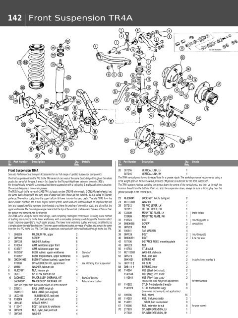
Front Suspension TR4A<br />
See also Performance & Tuning in Accessories for our full range of uprated suspension components.<br />
The front suspension from the TR2 to the TR6 series of cars was of the same basic design throughout the whole<br />
production period of the cars. It was in fact based on the Triumph Mayflower saloon of the early 1950’s.<br />
For the technically minded it’s an unequal wishbone suspension with a coil spring & a telescopic shock absorber.<br />
The actual design is in three main phases.<br />
The TR2 through to the very early 1962 TR4’s (chassis number CT6343 wire wheels, & CT6390 steel wheels), had<br />
the same basic design with the early type of upper ball joint (these are not handed), as it is called in Triumph<br />
parlance. The vertical post joining the upper ball joint & lower trunnion has zero castor. The later TR4’s from the<br />
above chassis numbers had a three degree castor system, which was also introduced with an improved top ball<br />
joint and necessitated the trunnions to be handed to achieve the angling of the vertical posts, and also offset the<br />
upper wishbones. The three degree angle means that the top of the vertical post is nearer the rear of the car than<br />
the bottom end screwed into the trunnion.<br />
The TR4A, whist using the same basic design, used completely redesigned components involving a new method<br />
of bushing the trunnions to the lower wishbones, with a removable pin being used through the trunnion which<br />
made ‘strip & re-assemble’ a much easier process. The lower inner wishbone bushes were also simplified to be<br />
a simple rubber to metal bonded item. The inner upper wishbone bushes are made of rubber and remain the same<br />
from the first TR2 to the last TR6. The TR4A suspension continued with little modification through to the last TR6.<br />
1 200659 FULCRUM PIN, upper 2<br />
2 GHF105 SCREW 8<br />
3 GHF333 WASHER, locking 8<br />
4 133504 ARM, wishbone upper front 2<br />
5 133507 ARM, wishbone upper rear 2<br />
6 102228* BUSH, rubber, upper wishbones 8 Standard<br />
TT3062* BUSH, Polyurethane, upper wishbones 4 Uprated<br />
NI QHQSK199S BUSH KIT(rubber bushes), upper/inner 1<br />
TT3160 UPRATED BUSH KIT, upper/inner 1 see ‘Uprating Your Suspension’<br />
7 WM69 WASHER, fulcrum pin 4<br />
8 NL607041 NUT, fulcrum pin 4<br />
9 PC10 SPLIT PIN, fulcrum nut 4<br />
10 GAC6067X MAJOR SUSP’ OVERHAUL KIT 1 Standard bushes<br />
GAC6067P MAJOR SUSP’ OVERHAUL KIT 1 Polyurethane bushes<br />
Both kits repair both sides and include all items marked*<br />
11 GSJ131 BALL JOINT (original) 2<br />
GSJ131B BALL JOINT (non-original) 2<br />
12 UKC3466 RUBBER BOOT, ball joint 2<br />
13 138869 CLIP, ball joint boot 2<br />
14 UHN445 GREASE NIPPLE 2<br />
15 112347 BOLT, ball joint to wishbone 4<br />
16 GHF223 NUT, nyloc, ball joint bolt 4<br />
17 GHF302 WASHER 4<br />
ill. Part Number Description Qty. Details<br />
No<br />
Req.<br />
20 307216 VERTICAL LINK, LH 1<br />
307215 VERTICAL LINK, RH 1<br />
The TR4A vertical posts have a threaded hole for a grease nipple. The workshop manual recommends using a<br />
EP90 weight gear oil. We have always preferred LM grease as lubricant for the front suspension.<br />
The TR4A system involves pumping the grease down the centre of the vertical post, and then up through the<br />
trunnion thread from the bottom. When you strip the suspension down, always be sure to thoroughly clear the<br />
grease passage in the vertical post.<br />
23 NL608041 LOCK-NUT, link to ball joint 2<br />
24 WC112081 WASHER 2<br />
25 307212 TIE ROD LEVER, LH 1<br />
307211 TIE ROD LEVER, RH 1<br />
30 133500 MOUNTING PLATE, LH 1 { brake caliper<br />
133499 MOUNTING PLATE, RH 1 }<br />
33 11<strong>83</strong>24 BOLT 1 { mounting plate to<br />
34 SH606065 SCREW 2 } vertical link<br />
35 GHF223 NUT 2<br />
36 106641 TAB WASHER 4<br />
39 GHF126 BOLT 2 { mounting plate<br />
40 BH606281 BOLT 2 } & tie rod lever<br />
42 107106 DISTANCE PIECE, mounting plate 4<br />
43 GHF223 NUT 4<br />
50 115763 STUB AXLE 2<br />
51 WC112081 WASHER, stub axle 2<br />
52 GHF275 NUT, stub axle 2<br />
GHK1021 BEARING KIT 2 includes items marked †<br />
55 GHS110 † OIL SEAL 2<br />
58 GHB111 † BEARING, inner 2<br />
60 114284 HUB (Steel) (with studs) 2 {<br />
114284A HUB (Alloy) (less studs) 2 |<br />
114284X HUB (Alloy) (less studs) 2 |<br />
(with extra thick flange for adjustment) | for steel wheels<br />
61 114282 STUD, front (standard length) 8 |<br />
114282X STUD, front (extra long) 8 |<br />
(may need shortening to suit application) |<br />
62 109586 NUT, wheel 16 }<br />
65 1142<strong>83</strong> HUB, (includes studs) 2 {<br />
66 114281 STUD, hub to extension 8 |<br />
67 110366 NUT, extension to hub 8 | for wire wheels<br />
70 217603 SPLINED EXTENSION, LH 1 |<br />
217602 SPLINED EXTENSION, RH 1 }