Delta Classic 301 - Blanes Pressure Solutions
Delta Classic 301 - Blanes Pressure Solutions
Delta Classic 301 - Blanes Pressure Solutions

You also want an ePaper? Increase the reach of your titles
YUMPU automatically turns print PDFs into web optimized ePapers that Google loves.
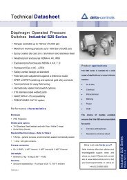
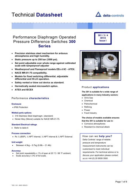
Technical Datasheet<br />
Performance Diaphragm Operated<br />
<strong>Pressure</strong> Difference Switches 300<br />
Series<br />
<strong>301</strong> / 3 / 4<br />
381/4<br />
Issue I<br />
• Precision stainless steel mechanism for arduous<br />
atmospheres and high humidity.<br />
• Static pressure up to 250 bar (3500 psi).<br />
• Set point adjustable over whole range against calibrated<br />
scale with tamperproof adjuster<br />
• Weatherproof and Flameproof models EEx d IIC - ATEX.<br />
• NACE MR-01-75 compatibility.<br />
• Models for fixed switching differential, adjustable<br />
differential and HI-LO operation.<br />
• Safety vented or blow out device as standard.<br />
• Hermetically sealed microswitch option.<br />
• ATEX and IECEX<br />
Performance characteristics<br />
Enclosure<br />
• IP66 Protection<br />
Wetted parts options<br />
• 316 Stainless Steel diaphragm. (standard)<br />
• Nickel Alloy (Monel) suitable for NACE MR-01-75.<br />
Standard Electrical ratings<br />
• Refer to table 6<br />
Process connection<br />
• Rc ¼ (BSP), ¼ NPT Internal, ½ NPT Internal & ½ NPT External.<br />
Unit weight<br />
• Between 4.5kg – 9.7kg (9.9lb – 21.4lb)<br />
Accuracy<br />
• Set point repeatability ± 1% of span at 20 °C / 68 °F ambient.<br />
• Scale accuracy ± 3% of full scale.<br />
Product applications<br />
The <strong>301</strong> is suitable for a wide range of<br />
applications in many Industry sectors:<br />
• Oil & Gas<br />
• Chemical<br />
• Petrochemical<br />
• Refining<br />
• Power<br />
• Food Industry<br />
The choice of models available ensures<br />
that the <strong>301</strong> is suitable for use in:<br />
• Corrosive atmospheres<br />
• Resistant to chemical attack<br />
How can we help you?<br />
<strong>Delta</strong> Controls’ range of reliable<br />
pressure and temperature<br />
measurement instruments can be<br />
customised to meet individual<br />
requirements. For technical advice or to<br />
discuss your application please contact<br />
us on +44 (0) 20 8939 3500<br />
Page 1 of 8<br />
TDS. <strong>301</strong>. 0805 ISSUE I
Enclosure<br />
TABLE 1<br />
FINISH<br />
All enclosures except Type A are<br />
finished in light grey epoxy resin<br />
paint. Special finishes to order.<br />
INTRINSIC SAFETY<br />
Because of the low voltages and<br />
currency of I.S. circuits, we<br />
recommend using gold and/or<br />
sealed contacts.<br />
WEATHERPROOF ENCLOSURES<br />
General Purpose<br />
The basic enclosure is pressure die-cast in zinc alloy, offering weather<br />
protection not less than NEMA 4 + 13/IP66.<br />
For Aggressive Atmospheres<br />
Investment cast enclosure in austenitic stainless steel with weather<br />
protection not less than NEMA 4X + 13/IP66.<br />
FLAMEPROOF ENCLOSURES CATEGORY 2 (ZONE 1)<br />
Code<br />
W<br />
A<br />
NOTE: Enclosure Codes W & A with<br />
range BC, C6, E1 and E8 (BU, CP,<br />
E4, E7) have weather protection<br />
reduced to IP54. In the interests of<br />
reliability not all enclosures are<br />
available with all wetter parts<br />
materials. See Table 4.<br />
EExd IIC T6 (-60 to + 40°C), T4 (-60 to +80°C) II 2 G D<br />
Gravity die-cast enclosure in aluminium-silicon alloy,<br />
certified to CENELEC EN50 014 and EN50 018.<br />
Suitable for outdoor use, IP66 / NEMA 4<br />
IECEx Exd11C certified to IEC 60079-0 and IEC60079-1<br />
II 2 G D<br />
H<br />
Temperatures in Table 1 refer to<br />
limitations for certified enclosures.<br />
See TECHNICAL DATA.<br />
EExd IIC T6 (-60 to + 40°C), T4 (-60 to +80°C) II 2 G D<br />
As Code H, but sand cast in high quality grey iron.<br />
IECEx Exd11C certified to IEC 60079-0 and IEC 60079-1<br />
II 2 G D<br />
K<br />
EExn ENCLOSURES CATEGORY 3 (ZONE 2)<br />
Type of Protection EExn II T6 (-20 to +40°C) II 3 G<br />
As code ‘W’ but EExn to EN50021.<br />
Weatherproof to NEMA 4/IP66.<br />
Limited switching facility (see table 6)<br />
As ‘N’ but with investment cast enclosure in austenitic stainless steel as<br />
‘A’.<br />
N<br />
O<br />
Models<br />
TABLE 2<br />
Maximum working pressures are<br />
as follows:<br />
<strong>301</strong>, 303, 381<br />
110 bar (1600 psi)<br />
304, 384<br />
250 bar (3500 psi)<br />
Fixed Switching Differential. See Tables 10A & 10C.<br />
Basic model giving close, fixed switching differential using<br />
proprietary microswitch operated by high integrity stainless steel<br />
mechanism. Set point field adjustable over full range against<br />
calibrated scale. SPDT & DPDT options available.<br />
Adjustable Switching Differential. (Wide Span) See Tables<br />
10B & 10D.<br />
Falling set point adjustable against a calibrated scale. Rising<br />
reset point adjustable to increase switching differential by up to<br />
50% of range.<br />
HI-LO Switching (Adjustable Gap) See Tables 10A & 10C. Two<br />
individual set points and separate electrical circuits, with<br />
independent adjustment against calibrated scale.<br />
Code<br />
<strong>301</strong><br />
304<br />
303<br />
381<br />
384<br />
Page 2 of 8
Electrical Entry<br />
Adaptors are available for other<br />
popular thread sizes.<br />
Enclosures ‘W’ and ‘N’<br />
Standard option code 1(22mm dia) is<br />
provided with a nylon 22/20 reducer<br />
and fibre washer suitable for a<br />
standard M20 cable gland and back<br />
nut. Option code 0 elbow adapter is<br />
factory fitted. Adapter kits may also<br />
be provided retrospectively to fit at<br />
site if required. Ask for details. See<br />
diagrams for dimensions<br />
‘W’ and ‘N’ SAFETY NOTE<br />
If a metal cable gland is site fitted it<br />
must either be earthed locally or an<br />
earth/gland plate must be used to<br />
connect the body of the gland at the<br />
enclosure earthing point. Earth/gland<br />
plates can be provided either factory<br />
fitted or in kit form for site assembly.<br />
Ask for details<br />
Material of Wetted Parts<br />
TABLE 3<br />
Code<br />
Enclosure W & N: Clearance for 20mm (3/4 in) outside dia conduit. 1<br />
Enclosures H, K & A: M20 x 1.5 ISO thread (direct). 0<br />
Enclosures H & K: M20 x 1.5 ISO thread, dual entry. 5<br />
Enclosures H & K: 3/4-NPT INT. 3<br />
Enclosures H & K: 3/4-NPT INT. dual entry 6<br />
Enclosure W: M20 x 1.5 elbow adaptor. 0<br />
Enclosure N: M20 x 1.5 straight adaptor (Approved). 0<br />
TABLE 4<br />
316 stainless steel diaphragm. All other wetted parts fully austenitic<br />
300 series stainless steel. PTFE and Nitrile seals.<br />
Nickel Alloy (Monel) diaphragm. All other wetted parts fully<br />
austenitic 300 series stainless steel. PTFE and Nitrile seals.<br />
For wetted parts required to conform with Sour Gas or Sour Crude<br />
applications as laid down in NACE standard MR-01-75<br />
Nickel Alloy (Monel) diaphragm and other wetted parts.<br />
PTFE and Viton seals. (NACE)<br />
316 Stainless Steel diaphragm.All other wetted parts fully austenitic<br />
300 Series stainless steel.P.T.F.E. and Viton seals<br />
Code<br />
I<br />
J<br />
L<br />
Q<br />
R<br />
Setting Ranges<br />
TABLE 5<br />
P max = maximum working pressure<br />
The instruments will sustain, without<br />
loss of performance, a continuous<br />
forward over pressure equal to the<br />
maximum static/line pressure and/or<br />
full vacuum.<br />
NOTE: For pressure difference<br />
switches maximum working pressure<br />
(P max ) and maximum static/line<br />
pressure mean the same.<br />
Maximum static pressure applied in<br />
the reverse direction (i.e. to LO port<br />
with HI port to atmosphere) will be<br />
contained without failure. The<br />
diaphragm will however have been<br />
distorted, leading to a degradation of<br />
performance and a shortening of the<br />
service life.<br />
For applications where regular<br />
reversals of pressure are inevitable, a<br />
special engineering facility is<br />
available.<br />
MODELS <strong>301</strong>/303/381<br />
P max<br />
RANGE<br />
bar psi mbar/bar Code in H 2 O/psi<br />
-12.5 to +12.5 BC* -5.0 to +5.0<br />
110<br />
1600<br />
3 to 25<br />
C6<br />
1 to 10<br />
OR<br />
5 to 120<br />
E1<br />
2 to 50<br />
50 to 350<br />
E8<br />
1 to 5<br />
0.1 to 1.5<br />
G5<br />
1 to 20<br />
(250)<br />
SEE MODELS<br />
(250)<br />
SEE MODELS<br />
(3500)<br />
(3500)<br />
0.2 to 4<br />
0.7 to 7<br />
1.5 to 15<br />
J0*<br />
M2*<br />
P8*<br />
2 to 60<br />
10 to 100<br />
20 to 200<br />
MODELS 304/384<br />
P max<br />
RANGE<br />
bar psi mbar/bar Code in H 2 O/psi<br />
-12.5 to +12.5 0C* -5.0 to +5.0<br />
110 OR 1600<br />
3 to 25<br />
06<br />
1 to 10<br />
5 to 120<br />
01<br />
2 to 50<br />
50 to 350<br />
08<br />
1 to 5<br />
0.1 to 1.5<br />
G5<br />
1 to 20<br />
0.2 to 4<br />
0.7 to 7<br />
1.5 to 15<br />
J0*<br />
M2*<br />
P8*<br />
2 to 60<br />
10 to 100<br />
20 to 200<br />
Code<br />
BU*<br />
CP<br />
E4<br />
E7<br />
GP<br />
J3*<br />
M8*<br />
PK*<br />
Code<br />
*Ranges BC/0C/BU/0U, J0/J3, M2/M8 and P8/PK not available on models 303, 381 and 384<br />
0U*<br />
0P<br />
04<br />
07<br />
GP<br />
J3*<br />
M8*<br />
PK*<br />
Page 3 of 8
Switching Options<br />
TABLE 6<br />
A much wider variety of switching options can be engineered to customer’s requirements for Model <strong>301</strong><br />
switches, including heavy DC, manual latching, pneumatic output etc. On models 303, 381 & 384 only<br />
the switching options specified can be supplied. Please consult our engineers for further information.<br />
Model <strong>301</strong>, 304<br />
UL/CSA Rating<br />
(RESISTIVE)<br />
§SEE NOTE<br />
Designation &<br />
Utilization<br />
Category<br />
IEC 947-5-1/EN 60947-5-1 Rating<br />
Rated operational current I VA Rating<br />
e<br />
(A) at rated operational<br />
Make Break<br />
U i U imp<br />
voltage U e<br />
Contact Code<br />
5 Amps @ 110/250V AC<br />
Light Duty for AC only<br />
AC14 D300 0.6/0.3A @ 120/240V AC<br />
DC13 R300 0.22/0.1A @ 125/250V DC<br />
250V<br />
0.8kV<br />
5 Amps @ 110/250V AC &<br />
2 Amps @ 30V DC<br />
AC14 D300 0.6/0.3A @ 120/240V AC<br />
General purpose precision DC13 R300 0.22/0.1A @ 125/250V DC<br />
250V 0.8kV<br />
1 Amp @ 125V AC &<br />
§100mA @ 30V DC gold alloy<br />
contacts for low voltage<br />
1 A @ 125 VAC RESISTIVE (IEC 1058-1/EN 61058-1)<br />
switching<br />
§ 5 Amps @ 110/250V AC &<br />
5 Amps @ 30V DC<br />
AC14 D300<br />
Environmentally sealed. DC13 R300<br />
§ 1 Amp @ 30V AC &<br />
30V DC Environmentally<br />
sealed with gold contacts<br />
5 Amps @ 250V AC and<br />
2 Amps @ 30V DC<br />
AC14 D300<br />
Hermetically sealed. Gold DC13 R300<br />
plated silver contacts.<br />
† 2 Single pole, double throw, simultaneous falling under pressure<br />
‡ 2 Single pole, double throw, simultaneous rising under pressure.<br />
Model 303<br />
5 Amps @ 110/250V AC &<br />
2 Amps @ 30V DC<br />
General purpose precision<br />
1 Amp @ 125V AC &<br />
§100mA @ 30V DC gold alloy<br />
contacts for low voltage<br />
switching<br />
Model 381, 384<br />
5 Amps @ 110/250V AC<br />
Light Duty for AC only<br />
5 Amps @ 110/250V AC &<br />
2 Amps @ 30V DC<br />
General purpose precision<br />
1 Amp @ 125V AC &<br />
§100mA @ 30V DC gold alloy<br />
contacts for low voltage<br />
switching<br />
§ 5 Amps @ 110/250V AC &<br />
5 Amps @ 30V DC<br />
Environmentally sealed.<br />
§ 1 Amp @ 30V AC &<br />
30V DC Environmentally<br />
sealed with gold contacts<br />
5 Amps @ 250V AC and<br />
2 Amps @ 30V DC<br />
Hermetically sealed. Gold<br />
plated silver contacts.<br />
0.6/0.3A @ 120/240V AC<br />
0.22/0.1A @ 125/250V DC<br />
250V<br />
0.5kV<br />
AC14 E150 0.3A @ 120V AC 125V 0.5kV 216 36<br />
AC14<br />
DC13<br />
AC14<br />
DC13<br />
AC14<br />
DC13<br />
AC14<br />
DC13<br />
D300<br />
R300<br />
D300<br />
R300<br />
D300<br />
R300<br />
D300<br />
R300<br />
0.6/0.3A @ 120/240V AC<br />
0.22/0.1A @ 125/250V DC<br />
0.6/0.3A @ 120/240V AC<br />
0.22/0.1A @ 125/250V DC<br />
250V<br />
250V<br />
0.5kV<br />
0.8kV<br />
1 A @ 125 VAC RESISTIVE (IEC 1058-1/EN 61058-1)<br />
0.6/0.3A @ 120/240V AC<br />
0.22/0.1A @ 125/250V DC<br />
0.6/0.3A @ 120/240V AC<br />
0.22/0.1A @ 125/250V DC<br />
250V<br />
250V<br />
0.8kV<br />
0.8kV<br />
432<br />
28<br />
432<br />
28<br />
432<br />
28<br />
432<br />
28<br />
432<br />
28<br />
432<br />
28<br />
432<br />
28<br />
72<br />
28<br />
72<br />
28<br />
72<br />
28<br />
72<br />
28<br />
72<br />
28<br />
72<br />
28<br />
72<br />
28<br />
SPDT<br />
DPDT<br />
SPDT<br />
DPDT<br />
SPDT<br />
DPDT<br />
SPDT*<br />
DPDT*<br />
SPDT*<br />
DPDT*<br />
SPDT<br />
DPDT<br />
SPDT<br />
DPDT<br />
SPDT<br />
DPDT<br />
00<br />
01<br />
02<br />
03<br />
04<br />
05<br />
08<br />
09<br />
0G<br />
0H<br />
H2<br />
H3†, H6‡<br />
02<br />
03<br />
04<br />
05<br />
SPDT 20<br />
SPDT 22<br />
1 A @ 125 VAC RESISTIVE (IEC 1058-1/EN 61058-1) SPDT 24<br />
0.6/0.3A @ 120/240V AC<br />
0.22/0.1A @ 125/250V DC<br />
250V<br />
0.5kV<br />
432<br />
28<br />
72<br />
28<br />
SPDT* 28<br />
AC14 E150 0.3A @ 120V AC 125V 0.5kV 216 36 SPDT* 2G<br />
AC14<br />
DC13<br />
D300<br />
R300<br />
0.6/0.3A @ 120/240V AC<br />
0.22/0.1A @ 125/250V DC<br />
The electrical rating is dependent on the microswitch fitted to the instrument. The electrical ratings defined by each approval that the microswitch complies<br />
with and is shown on the product nameplate, ie UL/CSA, or IEC. It should be noted that the instrument must be used within the electrical rating specified<br />
from the approval you require. This table lists the actual IEC ratings against the Designation & Utilization Category marked on the nameplates. In the<br />
absence of any verification by UL/CSA the microswitch § manufacturer’s rating is stated in italics and bold. If in doubt seek guidance from the factory.<br />
250V<br />
0.5kV<br />
NOTE: For low energy circuits e.g. 30V and up to 100mA, we recommend using gold alloy contact switches.<br />
U I = rated insulation voltage U imp = rated impulse withstand voltage across contacts.<br />
*Suitable for use with EExn Enclosures (Code N)<br />
432<br />
28<br />
72<br />
28<br />
SPDT<br />
H4<br />
Page 4 of 8
Process Connection<br />
TABLE 7<br />
Other thread specifications and<br />
sizes are available without using<br />
adaptors.<br />
Adaptors are available for<br />
applications where their use is<br />
permitted.<br />
Code<br />
Rc 1/4 (1/4 BSP tr INT) to ISO 7/1<br />
A<br />
1/4 – 18NPT INT F<br />
1/2 – 14NPT INT H<br />
1/2 – 14NPT EXT J<br />
Options & Treatments<br />
TABLE 8<br />
Combinations available, apply for<br />
details.<br />
Code<br />
Tropicalisation High humidity environment 01<br />
Marine and Offshore Saline atmosphere or salt spray 02<br />
Ammonia Process (wetted) parts and construction suitable for<br />
atmospheric ammonia.<br />
Oxygen Service 2: Process (wetted) parts are cleaned for oxygen. 04<br />
Oxygen Service3: Process and non-process parts are cleaned for<br />
use with oxygen.<br />
Stainless Steel Pipe Mounting Bracket Permits local 2” pipe work to<br />
be utilised for mounting the instrument.<br />
Tagging - Variety of tagging methods are available<br />
Applies when – no option is required and selection is made from<br />
special engineering.<br />
03<br />
05<br />
10<br />
APPLY FOR<br />
DETAILS<br />
00<br />
Special Engineering<br />
TABLE 9<br />
FEATURE<br />
Please consult <strong>Delta</strong> sales engineering for special requirements.<br />
Code<br />
TBA<br />
Page 5 of 8
Performance Data<br />
TABLE 10<br />
Bar Units (SI)<br />
TABLE 10A: 1 & 2.<br />
MODELS <strong>301</strong>, 304, 381, 384<br />
FIXED SWITCHING<br />
DIFFERENTIAL<br />
MODEL 381/384: The<br />
switching differential on each<br />
point may be up to 1.5 times<br />
that of Table 10A & 10C. Care<br />
must be exercised, therefore,<br />
in specifying high differential<br />
switches on sensitive ranges,<br />
or set point separation less<br />
than 3 times switching<br />
differential.<br />
TABLE 10B<br />
MODEL 303<br />
ADJUSTABLE SWITCHING<br />
DIFFERENTIAL<br />
MODEL <strong>301</strong> & (381) mbar units TABLE 10A:1<br />
Range Range<br />
SPDT OPTIONS<br />
DPDT OPTIONS<br />
Code mbar / bar 00 02 04 08/0G H2<br />
(20) (22) (24) (28/2G) (H4)<br />
01 03 05 09 / 0H H3 / H6<br />
BC<br />
C6<br />
E1<br />
E8<br />
G5<br />
J0<br />
M2<br />
P8<br />
-12.5 to +12.5<br />
3 to 25<br />
5 to 120<br />
50 to 350<br />
0.1 to 1.5<br />
0.2 to 4<br />
0.7 to 7<br />
1.5 to 15<br />
2<br />
2<br />
4<br />
10<br />
50<br />
100<br />
200<br />
300<br />
6<br />
6<br />
12<br />
30<br />
150<br />
300<br />
600<br />
900<br />
2<br />
2<br />
4<br />
10<br />
50<br />
100<br />
200<br />
300<br />
5<br />
5<br />
10<br />
20<br />
90<br />
200<br />
250<br />
500<br />
4<br />
4<br />
12.5<br />
17.5<br />
125<br />
300<br />
400<br />
600<br />
4<br />
4<br />
8<br />
20<br />
100<br />
200<br />
400<br />
600<br />
8<br />
8<br />
16<br />
40<br />
200<br />
400<br />
800<br />
1200<br />
4<br />
4<br />
8<br />
20<br />
100<br />
200<br />
400<br />
600<br />
10<br />
10<br />
25<br />
30<br />
115<br />
250<br />
300<br />
600<br />
20<br />
20<br />
50<br />
60<br />
230<br />
500<br />
600<br />
1200<br />
MODEL 304 & (384) mbar units TABLE 10A:2<br />
Range<br />
Code<br />
0C<br />
06<br />
01<br />
08<br />
G5<br />
J0<br />
M2<br />
P8<br />
MODEL 303 mbar units TABLE 10B<br />
Range<br />
Code<br />
C6<br />
E1<br />
E8<br />
G5<br />
Range<br />
mbar / bar<br />
-12.5 to +12.5<br />
3 to 25<br />
5 to 120<br />
50 to 350<br />
0.1 to 1.5<br />
0.2 to 4<br />
0.7 to 7<br />
1.5 to 15<br />
Range<br />
mbar / bar<br />
3 to 25<br />
5 to 120<br />
50 to 350<br />
0.1 to 1.5<br />
00<br />
(20)<br />
2<br />
2<br />
4<br />
10<br />
50<br />
100<br />
200<br />
300<br />
SPDT OPTIONS<br />
02 04 08 /0G<br />
(22) (24) (28/2G)<br />
6 2 5<br />
6 2 5<br />
12 4 10<br />
30 10 20<br />
150 50 90<br />
300 100 200<br />
600 200 250<br />
900 300 500<br />
H2<br />
(H4)<br />
4<br />
4<br />
12.5<br />
17.5<br />
125<br />
300<br />
400<br />
600<br />
DPDT OPTIONS<br />
01 03 05 09 / 0H H3 / H6<br />
4<br />
4<br />
8<br />
20<br />
100<br />
200<br />
400<br />
600<br />
8<br />
8<br />
16<br />
40<br />
200<br />
400<br />
800<br />
1200<br />
4<br />
4<br />
8<br />
20<br />
100<br />
200<br />
400<br />
600<br />
10<br />
10<br />
25<br />
30<br />
115<br />
250<br />
300<br />
600<br />
20<br />
20<br />
50<br />
60<br />
230<br />
500<br />
600<br />
1200<br />
SPDT OPTIONS<br />
DPDT OPTIONS<br />
02 04 03 05<br />
From To From To From To From To<br />
8 25 8 25 12 25 12 25<br />
15 120 15 120 22 120 22 120<br />
50 350 50 350 75 350 75 350<br />
150 750 150 750 225 750 225 750<br />
PSI Units<br />
TABLE 10C: 1 & 2<br />
MODELS <strong>301</strong>, 304, 381, 384<br />
FIXED SWITCHING<br />
DIFFERENTIAL<br />
Switching differentials<br />
in.H 2 O/psi.<br />
Due to manufacturing<br />
tolerances the figures quoted in<br />
these tables are for guidance<br />
only. Should the differential be<br />
critical for specific applications<br />
our engineers should be<br />
consulted prior to ordering.<br />
Flameproof models may be up<br />
to 2 times higher depending on<br />
the range. Should the<br />
differential be critical for specific<br />
applications our engineers<br />
should be consulted prior to<br />
ordering.<br />
TABLE 10D<br />
MODEL 303<br />
ADJUSTABLE SWITCHING<br />
DIFFERENTIAL<br />
MODEL <strong>301</strong> & (381) PSI units TABLE 10C:1<br />
Range<br />
Code<br />
BU<br />
CP<br />
E4<br />
E7<br />
GP<br />
J3<br />
M8<br />
PK<br />
Range<br />
in.H 2 0 / psi<br />
-5.0 to +5.0<br />
1 to 10<br />
2 to 50<br />
1 to 5<br />
1 to 20<br />
2 to 60<br />
10 to 100<br />
20 to 200<br />
00<br />
(20)<br />
0.8<br />
0.8<br />
1.6<br />
0.15<br />
0.7<br />
1.5<br />
2.9<br />
4.4<br />
SPDT OPTIONS<br />
02 04 08 /0G<br />
(22) (24) (28/2G)<br />
2.4 0.8 2<br />
2.4 0.8 2<br />
4.9 1.6 4<br />
0.45 0.15 0.3<br />
2.2 0.7 1.3<br />
4.4 1.5 2.9<br />
8.7 2.9 3.6<br />
13 4.4 7.5<br />
H2<br />
(H4)<br />
1.6<br />
1.6<br />
5<br />
0.25<br />
1.8<br />
4.3<br />
5.8<br />
8.7<br />
DPDT OPTIONS<br />
05 09 / 0H H3 / H6<br />
01 03<br />
MODEL 304 & (384) PSI units TABLE 10C:2<br />
Range<br />
Code<br />
0U<br />
0P<br />
04<br />
07<br />
GP<br />
J3<br />
M8<br />
PK<br />
Range<br />
in.H 2 0 / psi<br />
-5.0 to +5.0<br />
1 to 10<br />
2 to 50<br />
1 to 5<br />
1 to 20<br />
2 to 60<br />
10 to 100<br />
20 to 200<br />
00<br />
(20)<br />
0.8<br />
0.8<br />
1.6<br />
0.15<br />
0.7<br />
1.5<br />
2.9<br />
4.4<br />
SPDT OPTIONS<br />
02 04 08 /0G<br />
(22) (24) (28/2G)<br />
2.4 0.8 2<br />
2.4 0.8 2<br />
4.9 1.6 4<br />
0.45 0.15 0.3<br />
2.2 0.7 1.3<br />
4.4 1.5 2.9<br />
8.7 2.9 3.6<br />
13 4.4 7.5<br />
H2<br />
(H4)<br />
1.6<br />
1.6<br />
5<br />
0.25<br />
1.8<br />
4.3<br />
5.8<br />
8.7<br />
1.6<br />
1.6<br />
3.2<br />
0.3<br />
1.5<br />
2.9<br />
5.8<br />
8.7<br />
3.2<br />
3.2<br />
6.4<br />
0.6<br />
2.9<br />
5.8<br />
11.6<br />
17.5<br />
1.6<br />
1.6<br />
3.2<br />
0.3<br />
1.5<br />
2.9<br />
5.8<br />
8.7<br />
4<br />
4<br />
10<br />
0.45<br />
1.7<br />
3.6<br />
4.4<br />
8.7<br />
8<br />
8<br />
20<br />
0.9<br />
3.3<br />
7.3<br />
8.7<br />
17.5<br />
DPDT OPTIONS<br />
01 03 05 09 / 0H H3 / H6<br />
MODEL 303 PSI units TABLE 10D<br />
Range<br />
Code<br />
CP<br />
E4<br />
E7<br />
GP<br />
Range<br />
in.H 2 0 / psi<br />
1 to 10<br />
2 to 50<br />
1 to 5<br />
1 to 20<br />
1.6<br />
1.6<br />
3.2<br />
0.3<br />
1.5<br />
2.9<br />
5.8<br />
8.7<br />
3.2<br />
3.2<br />
6.4<br />
0.6<br />
2.9<br />
5.8<br />
11.6<br />
17.5<br />
1.6<br />
1.6<br />
3.2<br />
0.3<br />
1.5<br />
2.9<br />
5.8<br />
8.7<br />
4<br />
4<br />
10<br />
0.45<br />
1.7<br />
3.6<br />
4.4<br />
8.7<br />
8<br />
8<br />
20<br />
0.9<br />
3.3<br />
7.3<br />
8.7<br />
17.5<br />
SPDT OPTIONS<br />
DPDT OPTIONS<br />
02 04 03 05<br />
From To From To From To From To<br />
3.2 10 3.2 10 4.8 10 4.8 10<br />
5 48 5 48 8.9 48 8.9 48<br />
0.75 5 0.75 5 1.1 5 1.1 5<br />
2.2 11 2.2 11 3.5 11 3.5 11<br />
Page 6 of 8
Technical Specifications<br />
ACCURACY<br />
Set point repeatability + 1% of full scale<br />
at 20°C ambient.<br />
Scale accuracy +3% of full scale.<br />
AMBIENT TEMPERATURE RANGE<br />
All models are suitable for operating<br />
within a range of ambient temperature<br />
from –25 to +60°C (-13 to +140°F).<br />
Special build available for temperatures<br />
down to -60°C (-76°F)<br />
MAXIMUM PROCESS<br />
TEMPERATURE<br />
Subject to appropriate installation<br />
practice, the component parts will<br />
withstand +60°C (+140°F), for process<br />
temperatures up to +120°C (+248°F)<br />
order WETTED PARTS. Code R (Table<br />
4) and for higher temperatures refer to<br />
SPECIAL ENGINEERING.<br />
ENCLOSURES<br />
‘W’ & ‘N’<br />
‘A’ & ‘O’<br />
‘H’<br />
‘K’<br />
For range C6/CP add<br />
For series 304 add<br />
4.5kg/9.9Ib<br />
6.4kg/13.8Ib<br />
5.9kg/13.0Ib<br />
9.7kg/21.4Ib<br />
0.4kg/0.9Ib<br />
2.3kg/5.1Ib<br />
ELECTRICAL CONNECTIONS<br />
Terminal Block<br />
Cable entry is to a non-pinching<br />
terminal block made of a nonhygroscopic<br />
thermosetting plastic,<br />
suitable for cables up to<br />
2.5mm 2 /14AWG.<br />
Earthing/Grounding<br />
An earthing stud is provided inside all<br />
weatherproof enclosures, adjacent to<br />
the entry. External earthing is standard<br />
on flameproof versions. Safety note see<br />
Table 3.<br />
Dielectric Strength<br />
The electrical assembly is capable of<br />
withstanding *2kV between live parts<br />
and earth/ground and 500V between<br />
open contacts.<br />
*1.2kV for micro switch Codes H2, H3,<br />
H4 and H6. Refer to Table 6.<br />
Electrical Entry<br />
Standard options are listed in Table 3.<br />
Other threads can be accommodated<br />
by adaptors. Dual entry available, see<br />
Table 3.<br />
OPTIONAL EXTRAS<br />
Chemical Seals<br />
Chemical seals of our own or<br />
proprietary manufacture can be<br />
fitted when required.<br />
Mounting<br />
Position/Location/Installation<br />
Vertical as shown, IN<br />
DIMENSIONS, taking care to<br />
avoid siting in locations that<br />
transmit excessive shock or<br />
vibration. For further advice<br />
contact our engineers.<br />
Pollution degree (EN60947-5-1)<br />
All products are suitable for use in<br />
pollution degree 3. For extreme<br />
conditions where condensation<br />
may readily form, then sealed<br />
contacts should be used. See<br />
Table 6 codes 08/09, 0G/0H, 2G,<br />
28, H2/H3/H4/H6.<br />
Electrical Isolation – These<br />
products are not suitable for<br />
electrical isolation. Always isolate<br />
circuit separately to carry out any<br />
electrical work.<br />
Approvals<br />
INTRINSIC SAFETY<br />
Because of the low voltages and currents of intrinsically safe circuits, we<br />
recommend using gold contacts. Refer to Table 6.<br />
CENELEC/ATEX II 2 G D<br />
Certified to CENELEC EN50 014 and EN50 018.<br />
For use in Zone 1 hazardous areas EEx d IIC T6 (-60° to +40°C)<br />
T4 (-60° to +80°C)<br />
Enclosure Codes H and K and all models (see Table 1)<br />
Certificate number BAS01ATEX2426X<br />
IECEX APPROVAL for use in Zone 1 hazardous areas<br />
Exd IIC certified to IEC 60079-0 and IEC 60079-1<br />
Cert No. IECExITS04 0006X<br />
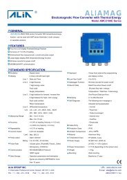
Dimensions<br />
PROPRIETARY<br />
GLAND<br />
Page 7 of 8
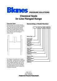
Dimensions<br />
All dimensions mm (inches)<br />
NOTE: Dimensions refer to<br />
ranges E1/E4 (Models <strong>301</strong>,<br />
303, 381); G5 (Models 304,<br />
384), and upwards<br />
Ranges C6/CP/BC/BU<br />
(Models <strong>301</strong> 303, 381);<br />
E8/E7 (Models 304, 384),<br />
and below, have flanges<br />
25mm (0.98in) larger in<br />
diameter.<br />
W & N Enclosure <strong>301</strong>/303/381 W & N Enclosure 304/384<br />
The distance between<br />
pressure connections is<br />
therefore increased by<br />
25mm (0.98in) and the<br />
stand-off from wall mounting<br />
by 12.5mm (0.49in).<br />
H & K Enclosure <strong>301</strong>/303/381 H & K Enclosure 304/384<br />
‘A’ & ‘O’ Enclosure <strong>301</strong>/303/381 ‘A’ & ‘O’ Enclosure 304/384<br />
In the interest of development and improvement <strong>Delta</strong> Controls Ltd, reserves the right to amend, without notice, details contained in<br />
this publication. No legal liability will be accepted by <strong>Delta</strong> Controls Ltd for any errors, omissions or amendments.<br />
<strong>Delta</strong> Controls Limited<br />
Island Farm Avenue, West Molesey, Surrey KT8 2UZ, UK.<br />
T+44 (0)20 8939 3500 F+44 (0)20 8783 1163 E sales@delta-controls.com W www.delta-controls.com<br />
Page 8 of 8