Renewable Energy System Installation Guide - Engenuity Systems ...
Renewable Energy System Installation Guide - Engenuity Systems ...
Renewable Energy System Installation Guide - Engenuity Systems ...

Create successful ePaper yourself
Turn your PDF publications into a flip-book with our unique Google optimized e-Paper software.
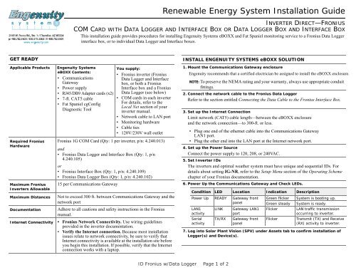
<strong>Renewable</strong> <strong>Energy</strong> <strong>System</strong> <strong>Installation</strong> <strong>Guide</strong><br />
INVERTER DIRECT—FRONIUS<br />
COM CARD WITH DATA LOGGER AND INTERFACE BOX OR DATA LOGGER BOX AND INTERFACE BOX<br />
This installa This installation guide provides procedures for installing <strong>Engenuity</strong> <strong>System</strong>s eBOXX and Fat Spaniel monitoring service to a Fronius Data Logger<br />
box, or to individual Data interface box, or to individual Data Logger and Interface boxes.<br />
GET READY<br />
Applicable Products <strong>Engenuity</strong> <strong>System</strong>s<br />
eBOXX Contents:<br />
• Communications<br />
Gateway<br />
• Power supply<br />
• RJ45/DB9 Adapter cards (x2)<br />
• 7-ft. CAT5 cable<br />
• Fat Spaniel cgConfig<br />
Diagnostic Tool<br />
Required Fronius<br />
Hardware<br />
Maximum Fronius<br />
Inverters Allowable<br />
Maximum Distances<br />
Documentation<br />
Internet Connectivity<br />
You supply:<br />
• Fronius inverter (Fronius<br />
Data Logger and Interface<br />
box, or both a Fronius<br />
Interface box and a Fronius<br />
Data Logger (see below)<br />
• COM cards in each inverter<br />
For details, refer to the<br />
Local Net section of your<br />
inverter manual.<br />
• Network cable to LAN port<br />
• Monitoring hardware<br />
• Cable ties<br />
• 120V/230V wall outlet<br />
Fronius 1G COM Card (Qty: 1 per inverter, p/n: 4.240.013)<br />
and<br />
• Fronius Data Logger and Interface Box (Qty: 1, p/n<br />
4.240.105)<br />
or<br />
• Fronius Interface Box (Qty: 1, p/n: 4.240.109)<br />
• Fronius Data Logger Box (Qty: 1, p/n: 4.240.102)<br />
15 per Communications Gateway<br />
Not to exceed 300 ft. between Communications Gateway and the<br />
network port<br />
Adhere to all cautions and safety instructions in the Fronius<br />
manual.<br />
• Fronius Network Connectivity. Use wiring guidelines<br />
provided in the inverter documentation.<br />
• Verify the Internet connection. Because most installation<br />
issues relate to network connectivity, be sure to verify that<br />
Internet connectivity is available at the installation site before<br />
you begin this installation. If possible, verify that the Internet<br />
connection works with a laptop.<br />
INSTALL ENGENUITY SYSTEMS eBOXX SOLUTION<br />
1. Mount the Communications Gateway enclosure<br />
<strong>Engenuity</strong> recommends that a certified electrician be assigned to install the eBOXX enclosure.<br />
NOTE: To preserve the NEMA rating and your warranty, always use appropriate conduit<br />
fittings.<br />
2. Connect the network cable to the Fronius Data Logger<br />
Refer to the section entitled Connecting the Data Cable to the Fronius Interface Box.<br />
Fronius Interface Box.<br />
3. Set up the Internet Connection<br />
Limit network (CAT5) cable length—between the eBOXX enclosure<br />
and the network connection—to 300-ft. or less.<br />
• Plug one end of the ethernet cable into the Communications Gateway<br />
LAN1 port.<br />
• Plug the other end into the LAN port at the Internet network port.<br />
4. Set up the Power Source<br />
Connect the power supply to 120, 208, or 240VAC.<br />
5. Set Inverter IDs<br />
The inverters and optimal weather system must have unique and sequential IDs. For<br />
details about setting IG-NR, refer to the Setup Menu section of the Operating Scheme<br />
chapter of your Fronius documentation.<br />
6. Power Up the Communications Gateway and Check LEDs.<br />
Condition LED Location Indication Description<br />
Power Up READY Gateway front<br />
panel<br />
LAN1<br />
activity<br />
Serial<br />
activity<br />
LINK<br />
TX/RX<br />
Gateway LAN1<br />
port<br />
Gateway front<br />
panel<br />
Green flicker<br />
Green steady<br />
Flicker<br />
Flicker<br />
<strong>System</strong> is booting up.<br />
<strong>System</strong> is ready.<br />
LAN traffic transmission<br />
occurring to inverter.<br />
Transmit (TX) and Receive<br />
(RX) activity to inverter.<br />
7. Log into Solar Plant Vision (SPV) under Assets tab to confirm installation of<br />
Logger(s) and Device(s).<br />
ID Fronius w/Data Logger Page 1 of 2
<strong>Renewable</strong> <strong>Energy</strong> <strong>System</strong> <strong>Installation</strong> <strong>Guide</strong><br />
INVERTER DIRECT—FRONIUS<br />
COM CARD WITH DATA LOGGER AND INTERFACE BOX OR DATA LOGGER BOX<br />
CONNECTING THE DATA CABLE TO THE FRONIUS INTERFACE<br />
BOX<br />
1. At the Fronius<br />
interface device,<br />
plug one adapter<br />
card into the data<br />
port.<br />
2. Insert the RJ45<br />
connector of the<br />
data cable into the<br />
RJ45 port of the<br />
adapter.<br />
3. At the<br />
Communications<br />
Gateway, plug the<br />
second adapter card<br />
into the DB9 port<br />
(labelled P1) on the<br />
gateway.<br />
4. Insert the RJ45<br />
connector of the<br />
data cable into the<br />
RJ45 port of the<br />
adapter.<br />
5. Set the baud rate<br />
on the Fronius box.<br />
SFS<br />
Adapter<br />
SFS<br />
Adapter<br />
straight-thru cat 5<br />
straight-thru cat 5<br />
Using a small screwdriver, turn the Baud rate dial until it points<br />
to 4.<br />
6. Return to the procedure entitled Install <strong>Engenuity</strong> <strong>System</strong>s eBOXX Solution.<br />
RFN<br />
Adapter<br />
RFN<br />
Adapter<br />
WIRING GUIDELINES<br />
Recommended straight-through CAT5 wire order EIA/TIA 568B:<br />
Troubleshooting Tips<br />
• Refer to the appropriate Fronius documentation to ensure the Fronius communications<br />
are correct.<br />
• Make sure the RS232 data cable between the Fronius box and the Communications<br />
Gateway does not exceed 50 ft. (18 m.).<br />
• Verify that all connections are solidly seated.<br />
• Verify that the Internet cabling does not exceed 300 ft. (100 m.)<br />
• Test for Internet connectivity with a laptop and the Fat Spaniel cgConfig Diagnostic Tool.<br />
• Make sure the Communications Gateway ethernet cable is connected before<br />
connecting the monitoring device to AC power.<br />
<strong>Engenuity</strong> <strong>System</strong>s Technical Support<br />
Phone:<br />
Pin #<br />
1-480-782-5600 or 1-800-375-3363 / tech@engenuity.com<br />
Color<br />
1 Orange/white<br />
2 Orange<br />
3 Green/white<br />
4 Blue<br />
5 Blue/white<br />
6 Green<br />
7 Brown/white<br />
8 Brown<br />
Copyright © 2010 <strong>Engenuity</strong> <strong>System</strong>s, Inc. All rights reserved.<br />
ID Fronius w/Data Logger Page 2 of 2