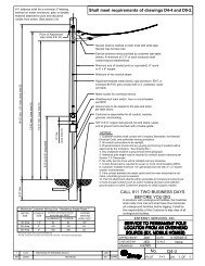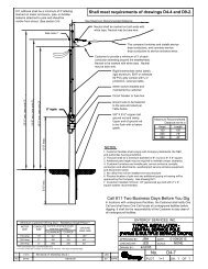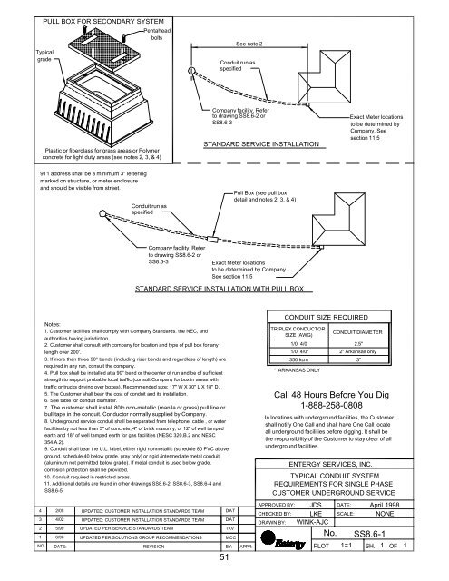
PULL BOX FOR SECONDARY SYSTEM - Entergy Texas
PULL BOX FOR SECONDARY SYSTEM - Entergy Texas
PULL BOX FOR SECONDARY SYSTEM - Entergy Texas

Create successful ePaper yourself
Turn your PDF publications into a flip-book with our unique Google optimized e-Paper software.
<strong>PULL</strong> <strong>BOX</strong> <strong>FOR</strong> <strong>SECONDARY</strong> <strong>SYSTEM</strong><br />
Typical<br />
grade<br />
Pentahead<br />
bolts<br />
See note 2<br />
Conduit run as<br />
specified<br />
Plastic or fiberglass for grass areas or Polymer<br />
concrete for light duty areas (see notes 2, 3, & 4)<br />
Company facility. Refer<br />
to drawing SS8.6-2 or<br />
SS8.6-3<br />
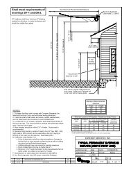
STANDARD SERVICE INSTALLATION<br />
Exact Meter locations<br />
to be determined by<br />
Company. See<br />
section 11.5<br />
911 address shall be a minimum 3" lettering<br />
marked on structure, or meter enclosure<br />
and should be visible from street.<br />
Conduit run as<br />
specified<br />
Pull Box (see pull box<br />
detail and notes 2, 3, & 4)<br />
Company facility. Refer<br />
to drawing SS8.6-2 or<br />
SS8.6-3<br />
Exact Meter locations<br />
to be determined by Company.<br />
See section 11.5<br />
STANDARD SERVICE INSTALLATION WITH <strong>PULL</strong> <strong>BOX</strong><br />
3<br />
2<br />
1<br />
Notes:<br />
1. Customer facilities shall comply with Company Standards. the NEC, and<br />
authorities having jurisdiction.<br />
2. Customer shall consult with company for location and type of pull box for any<br />
length over 200'.<br />
3. If more than three 90° bends (including riser bends and regardless of length) are<br />
required in any run, consult the company.<br />
4. Pull box shall be installed at a 90° bend or the center of run and be of sufficient<br />
strength to support probable local traffic (consult Company for box in areas with<br />
traffic or trucks driving over boxes). Recommended size: 17" W X 30" L X 18" D.<br />
5. The Customer shall bear the cost of conduit and its installation.<br />
6. See table for conduit diamater.<br />
7. The customer shall install 80lb non-metallic (manila or grass) pull line or<br />
bull tape in the conduit. Conductor normally supplied by Company.<br />
8. Underground service conduit shall be separated from telephone, cable , or water<br />
facilities by not less than 3" of concrete, 4" of brick masonry, or 12" of well tamped<br />
earth and 18" of well tamped earth for gas facilities (NESC 320.B.2 and NESC<br />
354.A.2).<br />
9. Conduit shall bear the U.L. label, either rigid nonmetallic (schedule 80 PVC above<br />
ground, schedule 40 below grade, gray only) or rigid /intermediate metal conduit<br />
(aluminum not permitted below grade). If metal conduit is used below grade,<br />
corrosion protection shall be provided.<br />
10. Conduit required in restricted areas.<br />
11. Additional details are found in other drawings SS8.6-2, SS8.6-3, SS8.6-4 and<br />
SS8.6-5.<br />
4 2/05 UPDATED: CUSTOMER INSTALLATION STANDARDS TEAM DAT<br />
NO.<br />
4/02<br />
5/99<br />
6/98<br />
DATE:<br />
UPDATED: CUSTOMER INSTALLATION STANDARDS TEAM<br />
UPDATED PER SERVICE STANDARDS TEAM<br />
UPDATED PER SOLUTIONS GROUP RECOMMENDATIONS<br />
REVISION<br />
DAT<br />
TKV<br />
MCC<br />
BY:<br />
51<br />
APPR:<br />
Call 48 Hours Before You Dig<br />
1-888-258-0808<br />
In locations with underground facilities, the Customer<br />
shall notify One Call and shall have One Call locate<br />
all underground facilities before digging. It shall be<br />
the responsibility of the Customer to stay clear of all<br />
underground facilities.<br />
APPROVED BY:<br />
CHECKED BY:<br />
DRAWN BY:<br />
CONDUIT SIZE REQUIRED<br />
TRIPLEX CONDUCTOR<br />
SIZE (AWG)<br />
ENTERGY SERVICES, INC.<br />
JDS<br />
LKE<br />
WINK-AJC<br />
PLOT<br />
No.<br />
CONDUIT DIAMETER<br />
1/0 4/0 2.5"<br />
1/0 4/0* 2" Arkansas only<br />
350 kcm 3"<br />
* ARKANSAS ONLY<br />
TYPICAL CONDUIT <strong>SYSTEM</strong><br />
REQUIREMENTS <strong>FOR</strong> SINGLE PHASE<br />
CUSTOMER UNDERGROUND SERVICE<br />
DATE:<br />
SCALE:<br />
April 1998<br />
NONE<br />
SS8.6-1<br />
1=1 SH. 1 OF 1
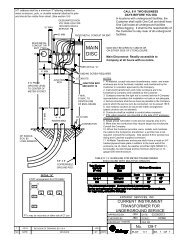
CONDUIT PLACEMENT<br />
Meter socket shall be designed for underground service installed and maintained by<br />
customer (Meter enclosure minimum required size is 4 1/8" D x 11" W x 15 1/2" H).<br />
Main breaker should be within 2'-0" of the meter. Outside wall recommended.<br />
911 address shall be a minimum 3" lettering<br />
marked on structure, or meter enclosure<br />
and should be visible from street.<br />
OR<br />
Note: Install conduit under meter<br />
socket on opposite side of switch<br />
Note: Install conduit under meter<br />
socket on opposite side of switch<br />
Call 48 Hours Before You Dig<br />
1-888-258-0808<br />
In locations with underground facilities, the<br />
Customer shall notify One Call and shall<br />
have One Call locate all underground<br />
facilities before digging. It shall be the<br />
responsibility of the Customer to stay clear<br />
of all underground facilities.<br />
Pad mount transformer or<br />
secondary pedestal (furnished<br />
and installed by Company)<br />
Conduit, elbow attachments,<br />
and bushings to be furnished<br />
and installed by Customer<br />
2'-0"<br />
See note 3.<br />
See drawing SS8.6-4<br />
Ground wire<br />
(see note 7)<br />
6'-5" working clearance (see note 6)<br />
5'-0" to 6'-0" (required)<br />
3' min.<br />
working<br />
clearance<br />
(see note 6)<br />
6" max.<br />
2<br />
Provided by<br />
the Company<br />
5/99<br />
DIRECT BURIED <strong>SYSTEM</strong><br />
(see note 5)<br />
Minimum Customer Wiring Size - Family Residence Single Phase<br />
METER<br />
SIZE<br />
100 Amp<br />
200 Amp<br />
320 Amp<br />
CONDUIT<br />
SIZE<br />
2"<br />
2.5" ***<br />
3"<br />
Current carrying & neutral<br />
wire size (per NEC)<br />
ALUMINUM<br />
COPPER<br />
4/0 2/0 #4 **<br />
Consult NEC<br />
UPDATED PER SERVICE STANDARDS TEAM<br />
GROUND<br />
WIRE SIZE<br />
#2 #4<br />
#6 *<br />
1 6/98 UPDATED PER SOLUTION GROUP RECOMMENDATIONS MCC<br />
2'-6"<br />
min.<br />
36" radius min.<br />
factory bend<br />
(If PVC, Sched.<br />
80 required.)<br />
IN CONDUIT <strong>SYSTEM</strong><br />
(see note 5)<br />
See NEC 310.15(B) (6) - phase conductors: NEC 220.61 - Neutral, and NEC 250.66 - Ground Wire<br />
* Wire smaller than #6 must be protected from physical damage (see NEC 250.120C)<br />
** For sole connection to rod, plate or pipe type electrode #6 AWG Cu is allowed (see NEC250.66A)<br />
*** Arkansas locations only allows 2"<br />
5 3/08 UPDATED: CUSTOMER INSTALLATION STANDARDS TEAM DAT<br />
4 2/05 UPDATED: CUSTOMER INSTALLATION STANDARDS TEAM DAT<br />
3 4/02 UPDATED: CUSTOMER INSTALLATION STANDARDS TEAM DAT<br />
NO. DATE: REVISION<br />
BY: APPR:<br />
52<br />
TKV<br />
APPROVED BY:<br />
CHECKED BY:<br />
DRAWN BY:<br />
5/8" x 8'-0"<br />
copper clad<br />
ground rod<br />
and clamp<br />
Upper end of ground rod<br />
to be flush with or below<br />
ground level<br />
NOTES:<br />
1. Customer facilities shall comply with Company Standards, the<br />
National Electrical Code, and authorities having jurisdiction.<br />
2. Meter enclosure shall be installed and maintained by the<br />
customer.<br />
3. Conduit system shall be installed to within 2'-0" of the<br />
transformer pad or secondary pedestal. End of conduit to be<br />
sealed and location marked. Consult Company for specific<br />
location.<br />
4. The customer shall install 80lb non-metallic (manila or grass)<br />
pull line or bull tape in the conduit. Conductor normally supplied<br />
by Company.<br />
5. Consult a Company Representative for required system in<br />
your area.<br />
6. See drawing SS8.6-6 for equipment work clearance.<br />
7. For grounding information see section 13.5.<br />
ENTERGY SERVICES, INC.<br />
PADMOUNT TRANS<strong>FOR</strong>MER OR <strong>SECONDARY</strong><br />
PEDESTAL SERVING A CUSTOMER<br />
JDS DATE: April 1998<br />
LKE SCALE: 3/8"=1'-0"<br />
WINK-AJC<br />
PLOT<br />
No.<br />
SS8.6-2<br />
1=1 SH. 1 OF 1
CONDUIT PLACEMENT<br />
Meter socket shall be designed for underground service installed and maintained by<br />
customer (Meter enclosure minimum required size is 4 1/8" D x 11" W x 15 1/2" H).<br />
Main breaker should be within 2'-0" of the meter. Outside wall recommended.<br />
OR<br />
Note: Install conduit under meter<br />
socket on opposite side of switch<br />
Call 48 Hours Before You Dig<br />
1-888-258-0808<br />
In locations with underground facilities, the<br />
Customer shall notify One Call and shall<br />
have One Call locate all underground<br />
facilities before digging. It shall be the<br />
responsibility of the Customer to stay clear<br />
of all underground facilities.<br />
Note: Install conduit under meter<br />
socket on opposite side of switch<br />
Threaded coupling, adapter, or<br />
sleeve as appropriate.<br />
6'-6" working clearance<br />
3' working<br />
clearance<br />
5'-0" min.-6'-0" max.<br />
(required)<br />
Ground wire to be sized per<br />
table below.<br />
6" max.<br />
When installing conduit system, Customer shall<br />
extend conduit to pole or underground system.<br />
Consult the Company for details. (See drawings<br />
SS8.6-2 and SS8.6-3)<br />
2'-6" min.<br />
See note 5<br />
See note 4<br />
5/8" X 12" steel dowels<br />
required when concrete<br />
encased.<br />
Notes:<br />
1. Customer facilities shall comply with Company Standards. the<br />
NEC, and authorities having jurisdiction.<br />
2. Concrete encasing on elbow is required where soil subsidence is<br />
possible, consult with Company.<br />
3. Conduit shall bear the U.L. label, either rigid nonmetallic<br />
(schedule 80 PVC above ground and schedule 40 PVC below<br />
ground, grey only) or rigid/intermediate metal conduit (aluminum<br />
not permitted below ground line). If metal conduit is used, corrosion<br />
protection shall be provided.<br />
4. Conduit shall be flush with wall. The foundation may be required<br />
to have blocked out area for conduit in order for conduit to be flush<br />
with wall when installed. Conduit is not allowed behind the wall.<br />
5. Upper end of ground rod to be flush with or below grade.<br />
6. Conduit required in restricted access or paved areas. (See<br />
section 8.6.1)<br />
7. Main breaker should be within 2'-0" of the meter. Outside wall<br />
recommended.<br />
8. Consult a Company Representative for required system in your<br />
area.<br />
IN CONDUIT <strong>SYSTEM</strong><br />
(see note 8)<br />
DIRECT BURIED <strong>SYSTEM</strong><br />
(see note 8)<br />
See note 2<br />
5/8" X 8'-0" copper clad<br />
ground rod and clamp<br />
36" radius factory bend<br />
(If PVC, schedule 80<br />
required.)<br />
Minimum Customer Wiring Size - Family Residence Single Phase<br />
METER<br />
SIZE<br />
100 Amp<br />
200 Amp<br />
320 Amp<br />
CONDUIT<br />
SIZE<br />
2"<br />
2.5" ***<br />
3"<br />
Current carrying & neutral<br />
wire size (per NEC)<br />
ALUMINUM<br />
COPPER<br />
4/0 2/0 #4 **<br />
Consult NEC<br />
GROUND<br />
WIRE SIZE<br />
#2 #4<br />
#6 *<br />
See NEC 310.15(B) (6) - phase conductors: NEC 220.61 - Neutral, and NEC 250.66 - Ground Wire<br />
* Wire smaller than #6 must be protected from physical damage (see NEC 250.120C)<br />
** For sole connection to rod, plate or pipe type electrode #6 AWG Cu is allowed (see NEC250.66A)<br />
*** Arkansas locations only allows 2"<br />
4 3/08 UPDATED: CUSTOMER INSTALLATION STANDARDS TEAM DAT<br />
4 2/05 UPDATED: CUSTOMER INSTALLATION STANDARDS TEAM DAT<br />
3 4/02 UPDATED: CUSTOMER INSTALLATION STANDARDS TEAM DAT<br />
2 5/99 UPDATED PER SERVICE STANDARDS TEAM TKV<br />
1 6/98 UPDATED PER SOLUTION GROUP RECOMMENDATIONS MCC<br />
NO. DATE: REVISION<br />
BY: APPR:<br />
54<br />
DETAILS <strong>FOR</strong> TYPICAL SINGLE<br />
PHASE RESIDENTIAL UNDERGROUND<br />
SERVICE AT HOUSE<br />
APPROVED BY:<br />
CHECKED BY:<br />
DRAWN BY:<br />
ENTERGY SERVICES, INC.<br />
JDS DATE: April 1998<br />
LKE SCALE: NONE<br />
WINK-AJC<br />
PLOT<br />
No.<br />
SS8.6-4<br />
1=1<br />
SH.<br />
1<br />
OF<br />
1
UNDERGROUND CLEARANCE<br />
<strong>FOR</strong> SWIMMING POOL<br />
UNDERGROUND REQUIREMENTS<br />
<strong>FOR</strong> PAVED AREAS<br />
POOL<br />
Connection<br />
point<br />
HOME<br />
5' min.<br />
Existing<br />
Company<br />
pole<br />
Electrical facilities and<br />
lines can never be<br />
within 5' of a pool<br />
(see NEC 680.10)<br />
Connection<br />
point<br />
HOME<br />
Existing<br />
Company<br />
pole<br />
Electrical lines<br />
under paved<br />
areas shall be in<br />
conduit<br />
UNDERGROUND FACILITIES<br />
CLEARANCES<br />
From shrubs, trees, buildings, fences, decks etc.<br />
DO NOT BLOCK ACCESS<br />
TO ELECTRICAL<br />
FACILITIES<br />
3' min.<br />
Proposed<br />
Driveway<br />
3'<br />
min.<br />
URD box<br />
(See<br />
note 2)<br />
12' min.<br />
(lock side)<br />
3'<br />
min.<br />
HOME<br />
Do not plant, pave, or<br />
build around electrical<br />
URD boxes,<br />
transformers, or<br />
cables not in conduit<br />
CAUTION:<br />
No gas<br />
meters<br />
within a 3'<br />
radius of<br />
meter<br />
enclosure<br />
METER CLEARANCES<br />
15"<br />
min.<br />
HOUSE<br />
Meter<br />
Socket<br />
3' min.<br />
15"<br />
min.<br />
No<br />
fences,<br />
clear<br />
shrubs,<br />
etc.<br />
For residential service, the meter is to be located on the<br />
outside of the building on the side of the residence within three<br />
feet of the front wall and outside of the fences on the side most<br />
economical to reach the company's facilities.<br />
Place temporary underground service<br />
wire here (underground 30" deep)<br />
Transformer<br />
Door<br />
Lock<br />
12"<br />
Street<br />
12"<br />
Pedestal<br />
Call 48 Hours Before You Dig<br />
1-888-258-0808<br />
In locations with underground facilities, the Customer shall notify One Call and<br />
shall have One Call locate all underground facilities before digging. It shall be<br />
the responsibility of the Customer to stay clear of all underground facilities.<br />
Notes:<br />
1. The customer is responsible for clearing and maintaining all right of way.<br />
2. Transformers must meet requirements of drawing SS10.1-1<br />
2 3/08 UPDATED: CUSTOMER INSTALLATION STANDARDS TEAM DAT<br />
1<br />
2/05<br />
UPDATED: CUSTOMER INSTALLATION STANDARDS TEAM<br />
NO. DATE: REVISION BY: APPR:<br />
56<br />
DAT<br />
APPROVED BY:<br />
CHECKED BY:<br />
DRAWN BY:<br />
ENTERGY SERVICES, INC.<br />
Underground Service Installation<br />
Details & Clearances<br />
JRH<br />
LKE<br />
DAT<br />
PLOT<br />
No.<br />
DATE:<br />
SCALE:<br />
1=1<br />
April 2002<br />
None<br />
SS8.6-6<br />
SH.<br />
1<br />
OF<br />
1
SOURCE<br />
120V<br />
120V<br />
240V<br />
GROUND<br />
STUD<br />
TO LOAD<br />
GROUND<br />
(PER NEC)<br />
TYPE S DETACHABLE<br />
3 WIRE SINGLE PHASE 120/240 VOLTS<br />
A teaser wire<br />
is required<br />
from the<br />
neutral lug to<br />
a 5th terminal<br />
mounted on<br />
the left side of<br />
the meter<br />
block<br />
between the<br />
line and load<br />
terminals.<br />
SOURCE<br />
GROUND<br />
STUD<br />
TO LOAD<br />
GROUND<br />
(PER NEC)<br />
TYPE S DETACHABLE<br />
3 WIRE SINGLE PHASE 120/208 WYE VOLTS<br />
LINE<br />
TO LOAD<br />
ABCN<br />
LINE<br />
TO LOAD<br />
ABCN<br />
ABCN<br />
GROUND<br />
(PER NEC)<br />
ABCN<br />
GROUND<br />
(PER NEC)<br />
SOURCE<br />
Ungrounded Conductor with the<br />
Higher Voltage to Ground (Phase<br />
marked C) must be marked<br />
orange (NEC 110.15 & 230.56)<br />
SOURCE<br />
Caution:<br />
For 277/480 volt service a<br />
disconnect shall be installed on<br />
the source side of the meter can.<br />
THREE PHASE 4 WIRE DELTA<br />
120 / 240 VOLTS<br />
THREE PHASE 4 WIRE WYE<br />
120 / 208 or 277/480 VOLTS<br />
Notes:<br />
1. All diagrams on this drawing show connections when the switch is installed on the right side (see Right Side below) of the meter<br />
socket. If the switch is installed on the left side of the meter socket you will need to mirror this diagram (see Left Side below).<br />
2. All sockets, except residential single phase less than 320 Amps, shall have a manual mechanical gang operated bypass switch.<br />
3. Load and supply wires shall not cross in the meter socket (11.1.2.7)<br />
NO.<br />
DATE:<br />
Note: Install conduit<br />
under meter socket on<br />
opposite side of switch<br />
CONDUIT PLACEMENT<br />
Meter socket shall be designed for underground service<br />
(installed and maintained by customer)<br />
Left Side<br />
OR<br />
REVISION<br />
Right Side<br />
Note: Install conduit<br />
under meter socket on<br />
opposite side of switch<br />
1 3/08 UPDATED: CUSTOMER INSTALLATION STANDARDS TEAM DAT<br />
83<br />
BY:<br />
APPR:<br />
APPROVED BY:<br />
CHECKED BY:<br />
DRAWN BY:<br />
ENTERGY SERVICES, INC.<br />
WIRING DIAGRAM CONNECTIONS<br />
<strong>FOR</strong> UNDERGROUND<br />
SELF CONTAINED METERS<br />
JRH<br />
JED<br />
DAT<br />
PLOT<br />
No.<br />
DATE:<br />
SCALE:<br />
SS11.8-2<br />
1=1<br />
APRIL 2005<br />
NONE<br />
SH.<br />
2 OF 2