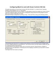
Download Modbus Register Map - Ocean Controls
Download Modbus Register Map - Ocean Controls
Download Modbus Register Map - Ocean Controls

Create successful ePaper yourself
Turn your PDF publications into a flip-book with our unique Google optimized e-Paper software.
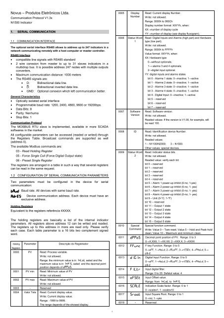
Novus – Produtos Eletrônicos Ltda.<br />
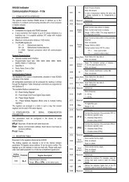
Communication Protocol V1.3x<br />
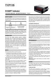
N1500 Indicator<br />
1. SERIAL COMMUNICATION<br />
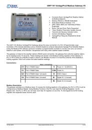
1.1 COMMUNICATION INTERFACE<br />
The optional serial interface RS485 allows to address up to 247 indicators in a<br />
network communicating remotely with a host computer or master controller.<br />
RS485 Interface<br />
• compatible line signals with RS485 standard<br />
• 2 wire conexion from master to up to 31 slaves indicators in a<br />
multidrop bus. It is possible address 247 nodes with multiple outputs<br />
converters.<br />
• Maximum communication distance: 1000 meters<br />
• The RS485 signals are:<br />
• D: Bidirectional data line.<br />
• D: Bidirectional inverted data line.<br />
• GND: Optional conexion which left communication better.<br />
General Characteristics<br />
• Optically isolated serial interface<br />
• Programmable baud rate: 1200, 2400, 4800, 9600 or 19200bps.<br />
• Data Bits: 8<br />
• Parity: Nenhuma<br />
• Stop Bits: 1<br />
Communication Protocol<br />
The MOSBUS RTU slave is implemented, available in more SCADA<br />
softwares in the market.<br />
All configurable parameters can be accessed (readed or writed) through<br />
the <strong>Register</strong>s Table. Broadcast commands are supported as well<br />
(address 0).<br />
The available <strong>Modbus</strong> commands are:<br />
03 - Read Holding <strong>Register</strong><br />
05 - Force Single Coil (Force Digital Output state)<br />
06 - Preset Single <strong>Register</strong><br />
The registers are arranged in a table in such a way that several registers<br />
can be read in the same request.<br />
1.2 CONFIGURATION OF SERIAL COMMUNICATION PARAMETERS<br />
Two parameters must be configured in the device for serial<br />
communication:<br />
bavd : Baud rate. All devices with same baud rate.<br />
adres : Device communication address. Each device must have an<br />
exclusive address.<br />
Holding <strong>Register</strong>s<br />
Equivalent to the registers referência 4XXXX.<br />
The holding registers are basically a list of the internal indicator<br />
parameters. All registers above address 12 can be writed and readed.<br />
The registers up to this address in more are read only. Please verify<br />
each case. Each table parameter is a 16 bits two complement signed<br />
word.<br />
Holding Parameter<br />
Descrição do Registrador<br />
<strong>Register</strong>s<br />
0000 PV Read: Process variable.<br />
Write: not allowed.<br />
Range: the minimum value is in inlol seted and the<br />
maximum value is in inkil seted and the decimal point<br />
position depends of dppos.<br />
0001 PV min Read: Minimum value of PV<br />
Write: not allowed.<br />
0002 PV max Read: Maximum value of PV<br />
Write: not allowed.<br />
0003 - Reserved<br />
0004 Valor Tela Read: Current display value.<br />
Write: Current display value.<br />
Range: -1999 to 9999.<br />
The range depends of the showed display.<br />
0005 Display<br />
Number<br />
0006 Status Word<br />
1<br />
0007 Software<br />
Version<br />
Read: Current display Number.<br />
Write: not allowed.<br />
Range: 0000h to 060Ch<br />
Display number format: XXYYh, when:<br />
XX→number of display cycle<br />
YY→number of display (see display fluxogram).<br />
Read: Digital Inputs and Alarms (high part) and Hardware<br />
type (low part).<br />
Write: not allowed.<br />
Range: 0000h to FFFFh<br />
Value format: XXYYh, when:<br />
XX: Hardware type<br />
0→without optionals;<br />
1→ alarms 3 and 4 optionals;<br />
2→digital input optional.<br />
YY: digital inputs and alarms states<br />
bit 0 - Alarme 1 state: 0→inactive; 1→active<br />
bit 1 - Alarme 2 state: 0→inactive; 1→active<br />
bit 2 - Alarme 3 state: 0→inactive; 1→active<br />
bit 3 - Alarme 4 state: 0→inactive; 1→active<br />
bit 4 - Digital Input: 0→inactive; 1→active<br />
bit 5 – reserved<br />
bit 6 – reserved<br />
bit 7 – reserved<br />
Read: Software version.<br />
Write: not allowed.<br />
Readed values: If the version is V1.00, for example, will<br />
be read 100.<br />
0008 ID Read: Identification device Number.<br />
Write: not allowed.<br />
Readed values:<br />
1 – N1100/N2000; 3 – N1500.<br />
Other values: special devices.<br />
0009 Status Word<br />
2<br />
Read: Indicator status bits.<br />
Write: not allowed.<br />
Readed value: verify each bit:<br />
bit 0 – reserved<br />
bit 1 – reserved<br />
bit 2 – reserved<br />
bit 3 – reserved<br />
bit 4 – reserved<br />
bit 5 – Alarm 1 power-up inhibit (0-no; 1-yes)<br />
bit 6 – Alarm 2 power-up inhibit (0-no; 1- yes)<br />
bit 7 – Alarm 3 power-up inhibit (0-no; 1- yes)<br />
bit 8 – Alarm 4 power-up inhibit (0-no; 1- yes)<br />
bit 9 – Unit (0-°C; 1-°F)<br />
bit 10 – reserved<br />
bit 11 – Output 1 state<br />
bit 12 – Output 2 state<br />
bit 13 – Output 3 state<br />
bit 14 – Output 4 state<br />
bit 15 – Output 5 state<br />
0010 Special<br />
Command<br />
Special function command.<br />
Write: Value 0 – Tare reset; Value 5 – Hold and Peak-hold<br />
clean; Value 10 – Maximum and minimum clean.<br />
0011 dppos Decimal point position of PV. Range: 0 to 3<br />
0→X.XXX; 1→XX.XX; 2→XXX.X; 3→XXXX<br />
0012 ffvnc F key Function. Range: 0 to 5<br />
0→oFF; 1→kold; 2→ALoFF; 3→rESEt; 4→Pkold; 5→<br />
tArE<br />
0013 digin Digital Input Function. Range: 0 to 5<br />
0→oFF; 1→kold; 2→ALoFF; 3→rESEt; 4→Pkold; 5→<br />
tArE<br />
0014 filtr Input digital filter.<br />
Range: 0 to 20. Defalut value: 4<br />
0015 ofset Input Offset value.<br />
Range: from inlol to inkil<br />
0016 S[ale Indication Scale factor. Range: 0 to 1<br />
0→scalex1; 1→scalex10<br />
0017 sroot Input Square Root. Range: 0 to 1<br />
0→no; 1→yes<br />
0018 - Reserved<br />
1
0019 alref Alarme Reference.<br />
Range: from inlol to inkil<br />
0020 ovtty Retransmision type of PV. Range: 0 to 1<br />
0→ 4 a 20mA retransmision; 1→0 a 20mA retransmision<br />
0021 Spal1<br />
Or<br />
Dfal1<br />
0022 Spal2<br />
Or<br />
Dfal2<br />
0023 Spal3<br />
Or<br />
Dfal3<br />
0024 Spal4<br />
or<br />
dfal4<br />
Alarm 1 Preset. Range: the minimum value is ininlol<br />
seted for not differential alarm or (inlol - inkil ) for<br />
differential alarm; The maximum value is in inkil seted<br />
for not differential alarm or (inkil - inlol ) if differential<br />
alarm.<br />
Alarm 2 Preset<br />
Range: same as spal1 or dfal1.<br />
Alarme 3 Preset<br />
Range: same as spal1 or dfal1.<br />
Alarme 4 Preset<br />
Range: same as spal1 or dfal1.<br />
0025 Fval1 Alarm 1 Function. Range: 0 to 6<br />
0→off; 1→ierr; 2→lo; 3→ki;<br />
4→difl; 5→difk; 6→dif.<br />
0026 Fval2 Alarm 2 Function<br />
Range: same as fval1.<br />
0027 Fval3 Alarm 3 Function<br />
Range: same as fval1.<br />
0028 Fval4 Alarm 4 Function<br />
Range: same as fval1.<br />
0029 Blal1 Alarm 1 power-up inhibit. Range: 0 a 1<br />
0→não; 1→sim.<br />
0030 Blal2 Alarm 2 power-up inhibit<br />
Range: same as blal1.<br />
0031 Blal3 Alarm 3 power-up inhibit<br />
Range: same as blal1.<br />
0032 Blal4 Alarm 4 power-up inhibit<br />
Range: same as blal1.<br />
0033 Kyal1 Alarm 1 Hysteresis (engineering unit)<br />
Range: 0 to span do sensor<br />
0034 Kyal2 Alarm 2 Hysteresis (engineering unit)<br />
Range: same as kyal1.<br />
0035 Kyal3 Alarm 3 Hysteresis (engineering unit)<br />
Range: same as kyal1.<br />
0036 Kyal4 Alarm 4 Hysteresis (engineering unit)<br />
Range: same as kyal1.<br />
0037 Intyp Input sensor type<br />
Range: 0 to 22.<br />
0→tc J; 1→tc K; 2→tc T; 3→tc E; 4→tc N; 5→tc R; 6<br />
→tc S; 7→tc B; 8→Pt100(degree decimal); 9→<br />
Pt100(degree unit); 10→Lin J; 11→Lin K; 12→Lin T; 13→<br />
Lin E; 14→Lin N; 15→Lin R; 16→Lin S; 17→Lin B; 18→<br />
Lin Pt100 degree decimal; 19→Lin Pt100; 20→0-<br />
50mV; 21→4-20mA; 22→0-5V<br />
0038 vnit Temperature Unit. Range: 0 to 1<br />
0→°C; 1→°F.<br />
0039 inlol Indication Low limit.<br />
Range: the minimum value depends of input type<br />
configured in intyp and the maximum is in inkil<br />
seted.<br />
0040 inkil Indication High limit.<br />
Range: from inlol to the input maximum configured in<br />
intyp.<br />
0041 adres Slave address<br />
Range: 1 to 247<br />
0042 bavd Communication Baud Rate. Range: 0 to 4<br />
0→1200;1→2400;2→4800;3→9600; 4→19200<br />
0043 Serial<br />
Number High<br />
Serial Number (High Display)<br />
Range: 0 to 9999. Read only<br />
0044 Serial<br />
Number Low<br />
Serial Numbe (Low Display)<br />
Range: 0 to 9999. Read only<br />
0045 Key Remote action of pressed key. Range: 0 to 9<br />
1→ ; 2→ ; 4→ ; 8→ BACK ; 9→ BACK and .<br />
0046 Al1t1 Alarm 1 Time 1 of timer. Range: 0 to 6500sec<br />
See operation manual for details.<br />
0047 Al1t2 Alarm 1 Time 2 of timer (in seconds)<br />
Range: same as al1t1.<br />
0048 Al2t1 Alarm 2 Time 1 of timer (in seconds)<br />
Range: same as al1t1.<br />
0049 Al2t2 Alarm 2 Time 2 of timer (in seconds)<br />
Range: same as al1t1.<br />
0050 Al3t1 Alarm 3 Time 1 of timer (in seconds)<br />
Range: same as al1t1.<br />
0051 Al3t2 Alarm 3 Time 2 of timer (in seconds)<br />
Range: same as al1t1.<br />
0052 Al4t1 Alarm 4 Time 1 of timer (in seconds)<br />
Range: same as al1t1.<br />
0053 Al4t2 Alarm 4 Time 2 of timer (in seconds)<br />
Range: same as al1t1.<br />
- Reserved<br />
- Reserved.<br />
- Reserved.<br />
- Reserved.<br />
- Reserved.<br />
- Reserved.<br />
- Reserved.<br />
0061 Inp.01 Custom linearization first value.<br />
0062 Inp.02 Custom linearization point #02<br />
0063 Inp.03 Custom linearization point #03<br />
0064 Inp.04 Custom linearization point #04<br />
0065 Inp.05 Custom linearization point #05<br />
0066 Inp.06 Custom linearization point #06<br />
0067 Inp.07 Custom linearization point #07<br />
0068 Inp.08 Custom linearization point #08<br />
0069 Inp.09 Custom linearization point #09<br />
0070 Inp.10 Custom linearization point #10<br />
0071 Inp.11 Custom linearization point #11<br />
0072 Inp.12 Custom linearization point #12<br />
0073 Inp.13 Custom linearization point #13<br />
0074 Inp.14 Custom linearization point #14<br />
0075 Inp.15 Custom linearization point #15<br />
0076 Inp.16 Custom linearization point #16<br />
0077 Inp.17 Custom linearization point #17<br />
0078 Inp.18 Custom linearization point #18<br />
0079 Inp.19 Custom linearization point #19<br />
0080 Inp.20 Custom linearization point #20<br />
0081 Ovt.01 Value to be displayed in point #01 of custom linearization<br />
(in engineering units)<br />
0082 Ovt.02 Value to be displayed in point #02 of custom linearization<br />
0083 Ovt.03 Value to be displayed in point #03 of custom linearization<br />
0084 Ovt.04 Value to be displayed in point #04 of custom linearization<br />
0085 Ovt.05 Value to be displayed in point #05 of custom linearization<br />
0086 Ovt.06 Value to be displayed in point #06 of custom linearization<br />
0087 Ovt.07 Value to be displayed in point #07 of custom linearization<br />
0088 Ovt.08 Value to be displayed in point #08 of custom linearization<br />
0089 Ovt.09 Value to be displayed in point #09 of custom linearization<br />
0090 Ovt.10 Value to be displayed in point #10 of custom linearization<br />
0091 Ovt.11 Value to be displayed in point #11 of custom linearization<br />
0092 Ovt.12 Value to be displayed in point #12 of custom linearization<br />
0093 Ovt.13 Value to be displayed in point #13 of custom linearization<br />
0094 Ovt.14 Value to be displayed in point #14 of custom linearization<br />
0095 Ovt.15 Value to be displayed in point #15 of custom linearization<br />
0096 Ovt.16 Value to be displayed in point #16 of custom linearization<br />
0097 Ovt.17 Value to be displayed in point #17 of custom linearization<br />
0098 Ovt.18 Value to be displayed in point #18 of custom linearization<br />
0099 Ovt.19 Value to be displayed in point #19 of custom linearization<br />
0100 Ovt.20 Value to be displayed in point #20 of custom linearization<br />
Digital Output States<br />
Equivalent to Coil Status (reference 0XXXX). The digital output states are basically<br />
the Boolean status of the respective digital outputs. The Read allows the actual<br />
2
state of digital outputs, regardless of their function.<br />
Writing to an output bit is only possible if the output has no function assigned to it<br />
(the output is configured to “OFF” in alarm cycle).<br />
Coil Status<br />
Output Description<br />
1 Alarm 1 Output status<br />
2 Alarm 2 Output status<br />
3 Alarm 3 Output status<br />
4 Alarm 4 Output status<br />
Exceptions - Error conditions<br />
The <strong>Modbus</strong> RTU protocol checks the CRC in the data blocks received.<br />
Reception errors are detected by the CRC, causing the indicator to discard the<br />
packet, not sending any reply to the master. After receiving an error-free packet, the<br />
indicator processes the packet and verifies whether the request is valid or not,<br />
sending back an exception error code in case of an invalid request.<br />
If a write command sends a out-of-range value to a parameter, the indicator clamp<br />
the value to the parameter range limits, replying with a value which reflects these<br />
limits (maximum or minimum value allowed for the parameter).<br />
Broadcast read commands are ignored by the indicator; only broadcast write<br />
commands are processed.<br />
Error Code<br />
81h<br />
82h<br />
83h<br />
Invalid command<br />
Error Description<br />
Invalid register number or out of range<br />
Invalid register quantity or out of range<br />
V1.3X July 2002<br />
3