Presentation by Dr. V. C. Sahni, Director, RRCAT - Raja Ramanna ...
Presentation by Dr. V. C. Sahni, Director, RRCAT - Raja Ramanna ...
Presentation by Dr. V. C. Sahni, Director, RRCAT - Raja Ramanna ...

Create successful ePaper yourself
Turn your PDF publications into a flip-book with our unique Google optimized e-Paper software.
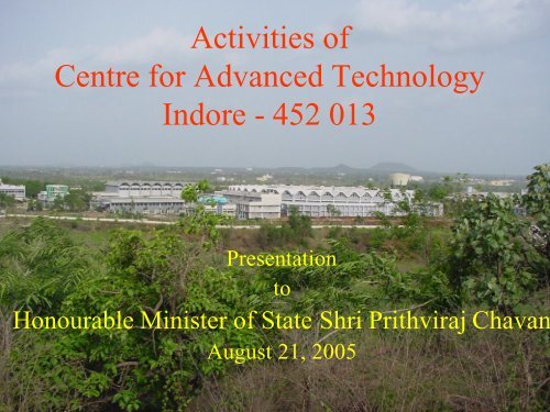
Activities of<br />
Centre for Advanced Technology<br />
Indore - 452 013<br />
<strong>Presentation</strong><br />
to<br />
Honourable Minister of State Shri Prithviraj Chavan<br />
August 21, 2005
An Overview of the Activities of Centre<br />
for Advanced Technology (CAT)<br />
CAT is the main R&D centre of DAE for Lasers and<br />
Accelerators, having branched off from BARC in early<br />
80’s. Its foundation stone was laid in 1984 and scientific<br />
activities got underway in 1986. Apart from accelerators,<br />
lasers and their applications, work is also going on laser<br />
materials, cryo-technology, low temperature physics etc.<br />
Present focus of accelerators is on SRS & radiation related<br />
applications, while in lasers our interests are : solid-state<br />
lasers, gas lasers (CVL, COIL, CO 2 etc.), semiconductor<br />
lasers, as well as their applications, such as, in industry,<br />
medicine, laser cooling of atoms, spectroscopy etc.
First Office Order
Foundation-Stone Laying Ceremony of CAT (Feb 19, 1984)<br />
Inauguration of CAT <strong>by</strong> president Giani Zail Singh, Seen along with him (L to<br />
R) are – <strong>Dr</strong>. R. <strong>Ramanna</strong>, Chairman, Atomic Energy Commission: Shri P. C.<br />
Sethi, Union Home Minister; Shri Arjun Singh, Chief minister of M.P. , Shri<br />
Bhagwat Dayal Sharma, Governor of M. P.; Shri Shivraj Patil, Union Minister<br />
for Energy, Shri Rajnedra Dharkar, Mayor, Indore Municipal Corporation &
Our Synchrotron Radiation Sources<br />
Indus-1 (450 MeV, 100 mA)<br />
(Operational since 1999)<br />
&<br />
Indus-2 (2.5 GeV, 300 mA)<br />
(Trials have begun to store the beam)<br />
Sharing common injectors viz<br />
a 20MeV Microtron & 700 MeV Booster
Hallmark of Our SRS Program is<br />
• Intense focus on indigenous development &<br />
qualification of most of the sub systems<br />
through home based efforts.<br />
• These include the magnets & their power<br />
supplies, vacuum chambers, ion pumps &<br />
gauges, beam diagnostic accessories, RF<br />
driver and control systems etc.<br />
• Vendor development for many high quality<br />
components for these accelerators.
TL-1<br />
TL-2<br />
TL-3<br />
Schematic view of Indus Complex
20 MeV Microtron
TL-1<br />
700 MeV Booster Synchrotron
Indus-1 Hall, Beam-lines, TL-2 & TL-3<br />
Towards<br />
Indus-2<br />
TL-3<br />
TL-2
Indus-1 Beam-lines : Monochromators<br />
used & wave lengths covered (in A)<br />
1. Reflectivity – TGM (40 – 100A)<br />
2. Photo physics – SN (500 – 2000A)<br />
3. Angle resolved PES – TGM (40 – 1000A)<br />
4. High resolution VUV Bl – RC (700 – 2000A)<br />
5. Angle integrated PES – TGM (60 – 1600A)<br />
6. Photoabsorption (PASS) – PGM (17 – 225A) $<br />
$ Under construction
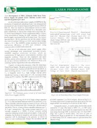
Reflectivity Beamline on Indus-1<br />
18<br />
(a)<br />
d = 89Å<br />
δ x 10 -3<br />
15<br />
12<br />
9<br />
0 200 400<br />
18<br />
(b)<br />
Mo<br />
16<br />
Mo/Si multilayer: Interfacial studies<br />
• Period 89Å (30Å Mo/ 59Å Si) 5<br />
• Reflectivity Measurement @ λ=80Å<br />
Reflectivity<br />
0.020<br />
0.015<br />
0.010<br />
0.005<br />
Measured at λ=80Å<br />
using four layer model<br />
using two layer model<br />
20 30 40<br />
Incidence Angle (deg)<br />
δ x 10 -3<br />
14<br />
12<br />
Si-on-Mo<br />
8Å<br />
Si<br />
40 50 60 70 80 90 100<br />
Depth in Å<br />
Mo-on-Si<br />
10Å<br />
Multilayer depth profile extracted<br />
from reflectivity data<br />
• Mo-on-Si Interface is thicker than the Sion-Mo<br />
interface<br />
• Interface asymmetry is due to large<br />
difference in thermal conductivities of Mo<br />
and Si
High Resolution VUV Beamline at Indus-1 (450 MeV)<br />
Synchrotron Source<br />
for<br />
High Resolution studies of Atoms/Molecules for probing<br />
high-lying energy states<br />
Identification of Rydberg states<br />
Determination of ionisation potential of atoms/molecules<br />
Measurement of photo-absorption cross-sections of individual and rotationally<br />
resolved absorption lines<br />
1.8<br />
1.6<br />
1.4<br />
1.2<br />
1261.55 A<br />
(Carbon)<br />
1243.18 A<br />
(Nitrogen)<br />
Vacuum UV line of<br />
carbon and nitrogen<br />
recorded <strong>by</strong> the<br />
spectrometer<br />
Signal (V)<br />
1.0<br />
0.8<br />
0.6<br />
1228.79 A<br />
(Nitrogen)<br />
0.4<br />
0.2<br />
40 60 80 100 120 140 160<br />
PMT position (mm)<br />
Wavelength Range:<br />
Monochromator:<br />
700-2000 Å<br />
Indigenous off-plane<br />
Eagle spectrometer
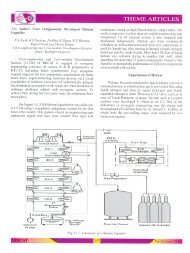
Indus – 2 lattice & its components<br />
Circumference:172.5m<br />
LS-5<br />
LS-6<br />
LS-4<br />
2 Bending magnets,<br />
4 Focussing quadrupoles<br />
5 Defocussing quadrupoles<br />
4 Sextupoles<br />
LS-7<br />
LS-3<br />
LS-8<br />
-1: used for injection<br />
-2 to LS-6: for insertion devices.<br />
-7: Unusable<br />
-8: for RF cavities<br />
LS-2<br />
LS-1
PARAMETERS OF Indus-2<br />
Maximum energy : 2.5 GeV<br />
Maximum current : 300 mA<br />
Lattice type : Expanded Chasman Green<br />
Superperiods : 8<br />
Circumference : 172.4743 m<br />
Bending field : 1.502 T<br />
Typical tune points : 9.2, 5.2<br />
Beam Emittance ex : 5.81x10 -8 mrad<br />
ey : 5.81x10 -9 mrad<br />
Available straight section : 5<br />
for insertion devices<br />
Maximum straight length : 4.5 m<br />
available for insertion devices<br />
Beam size sx : 0.234 mm<br />
(Centre of bending magnet) sy : 0.237 mm<br />
Beam envelope vacuum : < 1 x10 -9 mbar<br />
Beam life time : 15 Hrs<br />
RF frequency : 505.812 MHz<br />
Critical wavelength : 1.98 Å (Bending Magnet)<br />
0.596 Å (High Field Wiggler)<br />
Power loss : 186.6 kW (Bending magnet)<br />
Magnets:<br />
Dipoles : 16; Q’poles: 32 focusing & 40 defocusing type; S’poles: 32
Indus-2 OVERVIEW<br />
1997 : Decision to make 2.5 GeV energy machine<br />
1998- 2002 : Civil construction & infrastructure<br />
development, vendor identification, material<br />
procurement etc.<br />
2000-2004 : Subsystem fabrication & evaluation phase.<br />
2004 onwards: Subsystem installation & final<br />
commissioning.<br />
Cost : 95 Crores ( Cost of machine & building).<br />
Indigenous Systems Developed : Vacuum chambers,<br />
magnets, power supplies, beam diagnostics and RF<br />
power system etc.<br />
Imported Items: RF cavities & Klystrons.
Main Dipole Magnet for Indus-2. Yoke<br />
made <strong>by</strong> Godrej, Mumbai;coils <strong>by</strong> CAT<br />
(Field: 1.5T; Gap: 50mm; NI: 70,000 Amp turns)
Q’poles & S’poles made at CMTI & CAT<br />
(Q’p: Field:16T/m; Gap: 85 mm; NI:13,000 A turns)<br />
(S’p: Field: 400T/m2; Gap: 92 mm; NI: 5,700 A turns)
Indus-2 Dipole Power Supply<br />
One P/S for 16+1 dipole magnets, Min - Max current 200-900 Amp,<br />
Max Voltage 680 Volts
Indus-2 Q/P-1,2,3 Magnet P/S<br />
8+8+8 P/S for Q-pole magnets, Min - Max current 30-180 Amp,<br />
Max Voltage 87 - 119 Volts
Indus-2 Sextupole Magnet P/S<br />
Two P/S for 32 Sextupoles magnets, Min - Max current 40-230 Amp,<br />
Max Voltage 300 Volts
RF System<br />
Co-axial Line, Circulator & Klystron<br />
Klystron Tube & Auxiliary PS /<br />
Interlock<br />
Solid-state <strong>Dr</strong>iver Amplifier
Indus –2 RF Power System
Dipole Chambers<br />
vMaterial: Aluminium alloy A5083-H321 (Machining of 2 halves<br />
done <strong>by</strong> HAL; Welding plus leak checking etc. done at CAT)<br />
vTwo beam ports at 5 0 and 10 0 in each dipole chamber<br />
vAdditionally, port at 0 0 is also provided in five dipole chambers for<br />
insertion devices
• Photon Absorber<br />
‣To absorb unwanted<br />
photon x-ray radiation and<br />
protect the vacuum<br />
chambers<br />
‣Material: OFHC Copper
Beam diagnostics<br />
• Precision fabrication/ assembly<br />
• Calibration, fast signal processing<br />
• UHV compatibility<br />
• Devices used: Beam Position Monitors<br />
(Electrostatic pick-up), Beam Profile<br />
Monitors, Stripline Monitors, DCCT, Beam<br />
Scrapers, Wall current monitors, Secondary<br />
emission wire monitors, Sighting Beamline,<br />
Visible / X-ray diagnostic beam line.
Beam Diagnostics<br />
…cont.<br />
Beam profile monitor<br />
Horizontal Scraper during assembly
Control System … cont.<br />
Control room for Indus-1 and 2
Subsystem Qualification and Installation Details<br />
1. All vacuum chambers were baked to get ~10 -9 mbar<br />
before assembling in the ring.<br />
2. All p/s were tested with dummy loads.<br />
3. Field mapping done on each magnet. Data was used<br />
to optimize magnet locations ie “which one to<br />
place where”for best performance of ring.<br />
4. This optimization was arrived at using the simulated<br />
annealing algorithm.<br />
5. All Transfer Line (TL-3) & Indus-2 components<br />
were installed after full qualification.
Assembly of Indus-2 Ring in the Tunnel
RF Cavities Commissioned in Indus-2 Ring
Long Straight Section LS-6 Assembly
TL-3 Joining on to Indus-2
Status of Indus-2 as of August 20, 2005<br />
• Storage ring & TL-3 installation & evacuation completed.<br />
• Booster synchrotron operated upto ~ 550 MeV.<br />
• Dipole magnet P/S of Indus-2 connected and energized to a<br />
level so that ~ 700 MeV energy beam can be circulated.<br />
• All main subsystems can be controlled from Control Room<br />
Consoles and final tests have been completed.<br />
• On August 11, 2005 AERB gave consent to carry & inject up to<br />
10 mA beam into Indus-2 & raise its energy upto 2 GeV.<br />
• Trial experiments to store beam in Indus-2 started. First runs<br />
with 450 MeV beam from booster to injection point on Indus-2<br />
(via TL-2 and TL3) successfully completed ~ 8 pm on Aug 14,<br />
2005.<br />
• Beam quality improved & taken into the ring up to first BPM,<br />
(past kicker magnets K3 & K4) ~ 4:30 pm on August 20, 2005.
Indus-2 Ring<br />
WCM-3<br />
*69.7 m<br />
WCM-2<br />
*41.9 m<br />
TL-3<br />
TL-1<br />
TL-<br />
. Septum<br />
TL-3<br />
WCM-1<br />
*21.7 m<br />
Indus-1<br />
WCM-4<br />
*84.9 m<br />
Signals from Wall<br />
Current Monitors<br />
showing Beam<br />
Transmission<br />
through TL-3 on<br />
Aug 14, 2005<br />
* Number designates the distance from extraction point
Letter from Prof. Herman Winick from Stanford Linear Accelerator<br />
Centre, Stanford Synchrotron Radiation Laboratory, USA
Indus – 2 Team
Prototype Front-end of Indus-2 Beam-line
List of Beam-lines being built/designed/planned<br />
Range (KeV) Groups<br />
Being built<br />
XRD powder diffraction<br />
XRF-microprobe<br />
Energy Dispersive – XRD<br />
EXAFS<br />
Grazing incidence mag scattering<br />
PES<br />
Small angle X-ray scattering (SAXS)<br />
Being designed<br />
Protein Crystallography<br />
White-beam lithography<br />
MCD/PES on bending magnet<br />
Medical imaging beam-line<br />
Planned<br />
IR-beam-line<br />
Undulator-MCD<br />
Imaging beam-line<br />
Multipurpose white-EDXRD<br />
X-ray beam diagnostics<br />
Visible beam diagnostics<br />
5 – 25<br />
2 – 20<br />
10 – 70<br />
5 – 20<br />
5 – 15<br />
.08 - 15<br />
8 - 16<br />
6 – 25<br />
1 – 10<br />
0.03 – 4<br />
10 – 35<br />
2 – 100 mm<br />
0.1 – 1.5<br />
15 – 35<br />
5 – 40<br />
6.2<br />
Visible<br />
CAT<br />
CAT<br />
BARC<br />
BARC + UGC-DAE-CSR<br />
SINP, Kolkatta<br />
BARC<br />
BARC + UGC-DAE-CSR<br />
BARC + UGC-DAE-CSR<br />
CAT<br />
UGC-DAE-CSR<br />
BARC<br />
BARC<br />
CAT<br />
UGC-DAE-CSR<br />
UGC-DAE-CSR<br />
CAT<br />
CAT
Assembly of X-Ray Diffraction Beam Line BL-12
10MeV, 10kW Electron LINAC for food &<br />
medical product irradiation
Other Accelerators for Radiation<br />
Processing Applications<br />
1. Home Built DC Accelerator 500-750 KeV, 10 kW<br />
(Operational since 2003)<br />
2. 2.5 MeV, 100 kW DC Accelerator<br />
(Under development)
12 MeV Microtron Given to Mangalore University
DEVELOPMENT OF INDUSTRIAL &<br />
MEDICAL LASERS :<br />
vINDUSTRIAL Nd:YAG LASERS WITH<br />
FIBER OPTIC BEAM DELIVERY SYSTEM<br />
FOR INDUSTRIAL APPLICATIONS<br />
vHIGH PEAK POWER Nd:YAG LASERS<br />
vSURGICAL CARBON DI-OXIDE LASER<br />
WITH BEAM DELIVERY SYSTEM
Industrial YAG Laser
Laser based cutting and welding of coolant channel<br />
bellow lips for en-masse coolant channel replacement<br />
(EMCCR) in Pressurized Heavy Water Reactors (PHWR)<br />
•Nd:YAG laser with fiber optic beam delivery and motorized fixture<br />
motion from E-face of coolant channel<br />
•Cutting time for one bellow lip is typically 5minutes welding of the bellow<br />
lip takes about 8minutes<br />
•This will bring down radiation dose <strong>by</strong> over a factor of 50 compared to<br />
standard cutting techniques
Diode-pumped High Power CW IR Laser<br />
Geometry – Gold-coated Flow tube<br />
Diode stacks – Linear, 3x50W (TM Polarized)<br />
Pump Module – 3x Diode stacks<br />
120 °(Angular separation)<br />
Laser Type<br />
: Nd:YAG/1064nm<br />
Laser output<br />
: 200W, Multimode<br />
Diode pump power<br />
: 430W<br />
Optical-to-optical eff. : 46%<br />
Electrical-to-optical eff. : 23%(Highest reported)<br />
Applications: R&D, Medical and Industrial
High Average Power Green Laser<br />
Power : 75W at 30kHz<br />
Wavelength : 532nm<br />
pulse width : 200nsec<br />
power stability 20%<br />
Beam quality M 2
Ophthalmic Green Laser<br />
Diode-pumped frequency doubled Nd:YVO 4 system<br />
‣Transpupillary retinal photocoagulation<br />
‣Laser trabeculoplasty<br />
ower<br />
ode<br />
: 0-1000mW<br />
: True CW<br />
avelength: 532nm<br />
ulse duration : 50ms to 1000ms<br />
epeat interval : Variable (
SURGICAL MODEL C-40 CO 2 LASER<br />
Power : 40Watts<br />
Modes : CW<br />
Beam Delivery :<br />
Pulsed<br />
Chopped<br />
Aiming Beam : He-Ne<br />
Surgical : ENT<br />
Modalities<br />
7 Joint<br />
Articulated Arm<br />
Plastic Surgery<br />
General Surgery<br />
Gynecology<br />
Dermatology
Industrial Nd:YAG Lasers supplied <strong>by</strong> CAT to various DAE Units<br />
NRG(P), BARC<br />
Supplied to<br />
Fuel PIE Section, P.I.E. Division, BARC<br />
Remote Application Section, Back End Technology<br />
Development Division, Nuclear Recycle Group, BARC<br />
End use<br />
For end plate cutting of nuclear fuel<br />
bundles<br />
For Nuclear waste management<br />
For cutting and welding in hot cell<br />
BRIT, Mumbai<br />
PIRS, DPEND, IGCAR, Kalpakkam<br />
IDEAS, IGCAR, Kalpakkam<br />
NFC, Hyderabad<br />
CED, IGCAR, Kalpakkam:<br />
CED, IGCAR<br />
For brachytherapy and radiography<br />
capsule welding<br />
For cutting of spent fuel bundles<br />
For cutting and welding in hot cell<br />
For cutting of fuel pins to extract fuel<br />
pellets<br />
For thermal diffusivity measurement of<br />
materials<br />
250 Watt fiber coupled CW Nd:YAG for<br />
surface treatment
Home Built High Power CO2 Lasers<br />
3.5 kW CW CO2 Laser with CNC Workstation<br />
High Rep. Rate TEA CO 2<br />
Laser<br />
20 kW CW CO 2<br />
Laser
Applications of these High Power CO2 Lasers<br />
Laser Cutting<br />
Template for Accelerator<br />
Magnet: Iron Sheet<br />
Profile-cut<br />
Titanium sheet<br />
Laser cut 6” thick<br />
concrete block<br />
Contd…
Laser welded<br />
gear assembly<br />
Laser cladding<br />
Multi-layer<br />
cladded sample<br />
Laser cut souvenir
Laser Cooling and Trapping of Atoms<br />
t=3 ms 4 ms 5 ms<br />
Magneto-optic Trap for Rb atoms<br />
t=0 ms 1 ms 2 ms
Laser Plasma Interaction Studies<br />
Table- Top Terawatt laser<br />
High power Nd:glass laser<br />
system
Laser driven shock wave studies<br />
laser<br />
foil<br />
Streak<br />
Camera<br />
Optical fiber<br />
Experimental set-up for<br />
laser driven shock studies<br />
Streak camera signals
Laser based X-Ray sources<br />
Intense x ray generation in laser triggered<br />
vacuum discharge<br />
Cathode plasma jet<br />
pinching
BIOMEDICAL APPLICATIONS OF LASERS<br />
‣OPTICAL MICROMANIPULATION<br />
‣OPTICAL IMAGING<br />
‣OPTICAL DIAGNOSIS OF CANCER<br />
‣NARROW BANDWITH LIGHT EFFECTS ON<br />
CELLULAR CULTURES / ANIMAL MODELS
Optical micromanipulation<br />
Use of an asymmetric beam profile elliptic<br />
laser tweezers developed at BMAS<br />
Self-rotation of a<br />
normal RBC trapped<br />
<strong>by</strong> optical tweezers<br />
Intracellular trapping and<br />
displacement of chloroplasts in E.<br />
densa with a CW 1064 nm laser.<br />
The difference in rotational<br />
speed of RBCs from healthy<br />
volunteer and malaria
OPTICAL IMAGING<br />
DIFFUSIVE<br />
OUTPUT<br />
PULSE<br />
SNAKE LIKE<br />
BALLISTIC<br />
TURBID MEDIUM<br />
BALLISTIC<br />
BALLISTIC +<br />
SNAKE<br />
DIFFUSE<br />
DEPTH<br />
FEW mm<br />
FEW cm<br />
SEVERAL cms<br />
RESOLUTION<br />
~ µm<br />
~100µm<br />
~ mm
OPTICAL DIAGNOSIS OF CANCER- STUDIES ON RESECTED<br />
TISSUES<br />
F I (Counts)<br />
800 l ex = 337nm B<br />
NC<br />
400<br />
F I (Counts)<br />
600<br />
300<br />
l ex =337nm<br />
ORAL-C<br />
ORAL-N<br />
0.0<br />
375 450 525 600<br />
Wavelength (nm)<br />
0.0<br />
375 450 525 600<br />
Wavelength ( nm )<br />
SIGNIFICANT VARIATION IN FLUOROPHORE CONCENTRATION<br />
[C] NADH > [N] NADH & [B] NADH BREAST TISSUES Lasers Life Sci.,8, 249- 264, 1999<br />
[N] NADH > [C] NADH ORAL TISSUES Lasers Life Sci., 8, 211- 227, 1999<br />
ENZYMATIC MEASUREMENTS OF NADH CONSISTENT<br />
WITH SPECTROSCOPIC INFERENCE<br />
NADH CONCENTRATION<br />
(mM/gm TISSUE)<br />
1.5<br />
1.0<br />
0.5<br />
BREAST TISSUE<br />
M<br />
N<br />
Biotech. Appl. Biochem., 37, 45-50, 2003<br />
0.0<br />
1 2 3 4 5 6 7 8 9 10 11 12 13 14<br />
PATIENT NUMBER<br />
TIME RESOLVED STUDIES, DEPOLARISATION OF FLUORESCENCE, ..
THE LANCET Oncology, Vol. 2, May<br />
2001<br />
IN-VIVO STUDIES<br />
STUDIES ON NEOPLASM OF UTERINE CERVIX & ORAL<br />
CAVITY<br />
NON-LINEAR DIAGNOSTIC ALGORITHMS DEVELOPED<br />
SENSITIVITY : 95%<br />
SPECIFICITY : 96%<br />
Current Science, 79, 1089-1094 (2000)<br />
The Lancet Oncology, 2, 258, 2001<br />
Lasers in Surgery and Medicine, 33, 48-56 (2003).<br />
J. Biomed. Opt. (In Press)
SELF ROTATION OF RBC-<br />
DIAGNOSIS OF MALARIA<br />
Normal RBC<br />
Malariainfected<br />
Analysis of cells in a microflow<br />
Biotechnology Letters, 26, 971-974 (2004).
BURN WOUND INFECTED WITH PSEUDOMONAS RESISTANT TO ALL DRUGS<br />
WOUND AFTER 5 DAYS OF EXPOSURE TO 3mW AVERAGE POWER N 2<br />
LASER. CULTURE SHOWS INSIGNIFICANT GROWTH OF BACTERIA
Land Leveler Unit<br />
• The unit is useful to flatten ~300m<br />
diameter ground to within a cm.<br />
• Technology was developed as per<br />
request from MoA.<br />
•Successful trial conducted <strong>by</strong> PUSA<br />
Institute, Delhi.<br />
•Technology Transferred to OSAW,<br />
Ambala and would be integrated with<br />
tractors.<br />
•Other applications are also possible.
Single crystal growth Programme
DKDP crystal<br />
(Application in Pockels cells)<br />
Deuteration<br />
level: >98%
Conversion efficiency 62% without<br />
accounting for Fresnel losses.<br />
KTP crystals<br />
Single crystals of<br />
potassium titanyl<br />
phosphate (KTP), grown<br />
<strong>by</strong> TSSG technique<br />
SHG elements<br />
Laser used: electro-optically Q-switched pulsed<br />
Nd:YAG laser in an extra-cavity configuration, with<br />
a pulse duration of 8-9 ns.<br />
The maximum intensity incident on the KTP<br />
element of 6 mm interaction length was<br />
approximately 207 MW/cm 2 .
Systems developed
ZnS Dome for Seeker Missile<br />
‘Nag’
Production of large sized transparent ceramics is going on
DAE-CERN COLLABORATION<br />
1991: DAE-CERN Cooperation agreement<br />
1996 : Decision to contribute to LHC<br />
India has joined LHC project under a DAE-CERN<br />
cooperation agreement, with DAE Centres, like, CAT,<br />
BARC, ECIL etc., and many other agencies contributing to<br />
its construction.<br />
By now our in kind contribution is ~40 MCHF, covering<br />
delivery of a variety of components and subsystems for<br />
LHC and providing skilled manpower support for<br />
magnetic tests and measurements at CERN.
Details of Indian contribution to LHC<br />
Participation in accelerator construction: delivering subsystems<br />
e.g. PMPS Jacks, SC Corrector Magnets,<br />
QHPS,QDE, Circuit Breakers etc;<br />
Participation in CMS and ALICE detector R&D and also<br />
installation of HO & ECAL (for CMS) etc., PMD &<br />
MUON Chamber (for ALICE).<br />
Contribution to GRID computing software development;<br />
setting up a Regional Tier 2 Centre
Requirements of the PMPS Jacks (being<br />
entirely made <strong>by</strong> India) to support full<br />
LHC, all along the 27 Km tunnel<br />
üPrecise alignment of ~ 1250 Numbers of 32 Ton, 15<br />
meter Superconducting magnets of the LHC collider<br />
with a setting resolution of 50 micron,<br />
üThis is equivalent to moving the weight of eight<br />
elephants <strong>by</strong> the breadth of a human hair.<br />
üNumbers Required ~ 6800 jacks.<br />
üThe Jacks were Designed & Developed <strong>by</strong> a team from<br />
Centre for Advanced Technology. Mass produced <strong>by</strong><br />
AAL & IGTR and supplied under responsibility of CAT,<br />
as part of CERN-DAE collaboration agreement.
Precision alignment JACKS for LHC cryomagnets (weighing 32 Tons)<br />
Test Set-up to demonstrate setting resolution of 0.02 mm
Cryo-magnet installation in the LHC<br />
tunnel on the Indian made jacks
Decapole & Octupole corrector<br />
magnet assembly<br />
Cryogenic test facility at CAT, Indore<br />
Warm magnet measurement setup at CAT
Correcter Magnets for LHC Diploes
Cryocoolers<br />
Indigenous Development of<br />
Turbo Molecular Pump
Thank you