Full Service Manual - Pennsylvania Scale Company
Full Service Manual - Pennsylvania Scale Company
Full Service Manual - Pennsylvania Scale Company

Create successful ePaper yourself
Turn your PDF publications into a flip-book with our unique Google optimized e-Paper software.
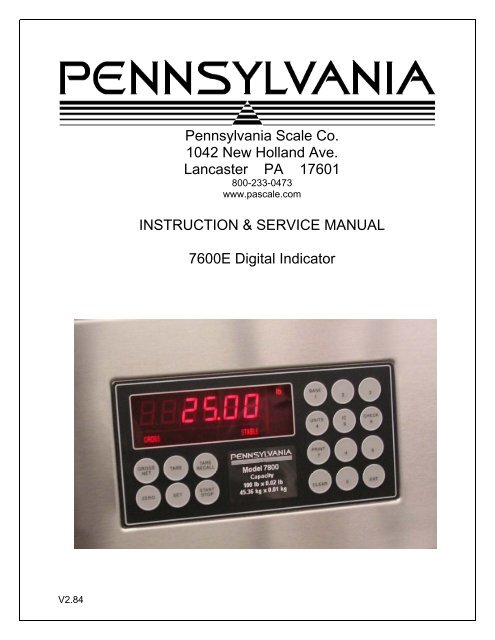
<strong>Pennsylvania</strong> <strong>Scale</strong> Co.<br />
1042 New Holland Ave.<br />
Lancaster PA 17601<br />
800-233-0473<br />
www.pascale.com<br />
INSTRUCTION & SERVICE MANUAL<br />
7600E Digital Indicator<br />
V2.84
TABLE OF CONTENTS<br />
SPECIFICATIONS………………………………………3<br />
INSTALLATION…………………………………………4<br />
SETUP ACCESS………………………………………..5<br />
MENU LAYOUT...………………………………………6<br />
CONFIGURATION……………………………………..7<br />
REMOTE SERIAL DISPLAY………………………….8<br />
CALIBRATION………………………………………….9<br />
SERIAL PORTS………………………………………10<br />
SERIAL COMMUNICATIONS……………………….11<br />
ANALOG OUTPUT……………………………………13<br />
DIGITAL INPUT/OUTPUT……………………………15<br />
SETPOINTS……………………………………………16<br />
OVER/UNDER…………………………………………17<br />
BATCH MODE…………………………………………18<br />
SERIAL COM. SETPOINT/ACC……………………...19<br />
TIME & DATE………………………………………….20<br />
WEIGH IN/OUT………………………………………..21<br />
SMART SERIAL……………………………………….23<br />
ASCII CHART………………………………………….28<br />
DISPLAY MESSAGES………………………………..32<br />
115/220 VAC…………………………………………..33<br />
SPARE PARTS………………………………………..34<br />
2
SPECIFICATIONS<br />
Smart Serial Setup: 8 custom print files plus 8 macro files, 30 characters each.<br />
Batch Start/Stop: Control from front panel or remote input.<br />
Setpoint Operation: 4 output relays configurable for normal setpoints, over/under or<br />
manual/auto batch modes.<br />
LOAD CELL A/D CONVERTER<br />
TYPE: 24 bit delta sigma<br />
EXCITATION: 5 VDC, 120 mA max.<br />
SIGNAL INPUT: 16 mv<br />
SENSITIVITY: 0.1 uV/grad<br />
UPDATE RATE: 30 update/second<br />
DISPLAY: Six (6) Decades, 0.6 inch LED<br />
KEYPAD: <strong>Full</strong> numeric plus controls<br />
POWER INPUT: 117/217 VAC, 50-60 HZ, 20 watts, fuse 0.25 A Slo-Blow.<br />
SERIAL PORTS:<br />
Port 1: RS232C or 20ma<br />
Port 2: RS485, RS232C or 20mA.<br />
ENCLOSURE: Stainless Steel, NEMA 4x, Tilt - Stand Base, 7lbs.<br />
CASE: 9” (w) x 6.44” (h) x 4” (d) Tilt or panel mount.<br />
OPTIONS:<br />
TIME & DATE: 12/24 hr, battery backed.<br />
ANALOG OUTPUT: 0-10v, 4-20ma (16 bit D/A).<br />
DIO: 4 AC/DC – inputs, 4 AC outputs (SS Relays, 0.5 amp)<br />
Optional Case: 10” (w) x 6.5” (h) x 4” (d) Tilt only.<br />
Panel Mount: Kit (replaces tilt stand).<br />
3
INSTALLATION<br />
POWER WIRING: The indicator is designed to be operated from 117/217 VAC, 50-60 Hz. The<br />
unit power cord must be plugged into a grounded 3 - wire polarized AC wall socket. All normal<br />
wiring and grounding precautions should be observed, including use of a "clean" AC power<br />
line.<br />
SCALE WIRING:The unit is equipped with cable gland entry for load cell cable insertion and<br />
internal (pluggable) terminal strip for 4 / 6 wire connection. Remove sense jumpers P11-8/7,<br />
P11-6/5 for six wire.<br />
Transformer<br />
P12<br />
F1<br />
0.25A<br />
SB<br />
Line<br />
Filter<br />
A<br />
J1<br />
B<br />
1 2<br />
P5<br />
Shielded<br />
A/D Converter<br />
SW4<br />
8 7 6 5 P11<br />
CAL<br />
EW-1000 Rev…..<br />
6 5 4 3 2 1 TB-1<br />
Excitation +<br />
Sense +<br />
Excitation –<br />
Sense -<br />
Signal +<br />
Signal -<br />
4
SETUP ACCESS<br />
To access instrument configuration, calibration or to enable options, depress the “Zero” key for<br />
five seconds.<br />
The Audit Trail counters (“Pxxxx” and “Cxxxx”) are displayed first followed by access code<br />
request (“AC?”). The initial factory setting is “0000” which can be entered with four steps of the<br />
“Gross/Net” key (“AC0000”) and “Print”. If no entry is made, instrument returns to operate<br />
mode.<br />
The access code can be changed to any four digit combination during setup exit when display<br />
again shows “AC?”.<br />
The “Check” key provides the software version “V 1.XX” followed by the display test routine.<br />
Use the “ENT” key to advance to the keyboard test and to exit tests.<br />
After entry, use the “Tare Recall” key to select a main menu; configuration (“SEL.CFG”),<br />
calibration (“SEL.CAL”), or options (“SEL.OPX”) and “Start/Stop” to back step.<br />
The “Gross/Net” key enters selected menu and is used to step through sub categories.<br />
Individual parameter selection is made with the “Tare/Recall” key, which then steps through<br />
the parameter choices (“Zero” key back steps within the menu).<br />
The “ENT” key is used at any point to “back” up from categories to menus and to “save?” and<br />
“AC?” and exit.<br />
During the exit steps, if changes were made, the display is “save?” with alternate “no”. To save<br />
changes, use the “Units” key to select “yes” and “ENT” to exit.<br />
Calibration numeric entries are entered directly followed with the “ENT” key.<br />
Front panel access is inhibited if conventional “sealing” is applied by<br />
setting jumper J1-1 in the B position. The board mounted “CAL” button is<br />
then used for access.<br />
5
Menu Layout<br />
CFG<br />
Configuration: Divisions, count by, decimal, over<br />
range, filter, AZM, zero range, ISM, lb/kg, serial port<br />
selection, DIO enable<br />
CAL<br />
Calibration: Zero, Span<br />
OP1<br />
Analog Output: Gross, Net, Display; Zero, Span, Trim<br />
OP2<br />
Setpoint DIO: Setpoint, Over/Under, <strong>Manual</strong> / Auto Batch<br />
OP3<br />
Time & Date: 24 hr, 12 hr, Print format<br />
OP4<br />
Weigh – In / Weigh – Out: Truck mode<br />
OP5<br />
10 Point Linearity, Filter selection<br />
OP6<br />
Totalizer<br />
OP8<br />
OP7<br />
Smart Serial<br />
AC/DC Battery<br />
6
CONFIGURATION: “SEL.CFG” Use Gross/Net to enter the menu and step to each category,<br />
Tare Recall to select parameters. ENT to return to menu selection.<br />
Capacity is the combination of “1”, “2” and “3”.<br />
Example: 1__100, 2___2 and 3__0.0 = 2,000 x 0.2 lb<br />
Step Parameters Definition<br />
1 5, 10, 15, 20…100, 120…1000<br />
Number of divisions x100<br />
100 = 10,000 divisions<br />
2 1, 2, 5, 10, 20, 50, and 100.<br />
Count by selection<br />
10,000 divisions, count by 2 = 20,000<br />
3 0, 0.0, 0.00, 0.000, and 0.0000 Decimal point selection<br />
4 105P, 9 d (105% or 9 divisions) Overrange selection<br />
5 1, 2, 3, 4, 5, 6, 8, 10, 12, 15……90 Digital filter selection (averaging)<br />
6 off, 0.5, 1, 3, 5, 10 (divisions) Auto Zero Maintenance (AZM)<br />
7 1.9, 5, 10, 20, FS (% of capacity)<br />
Zero range selection<br />
1.9% of 2,000 x 0.2 = 38.0 lb<br />
7.1 off, on (ISM) Zero’s scale on power-up<br />
8 off, 1, 3, 5,10 (divisions) Motion Band selection<br />
9 lb, kg, con Units selection and convert<br />
10 nt, Gtn, n.nt, n.Gtn.<br />
Port 1 serial output selection<br />
nt display only, Gtn is Gross Tare Net<br />
and n.nt/n.Gtn inhibit negative gross<br />
printing<br />
11 off, co, de Off, Continuous, or Demand<br />
12 7o, 7E, 8n 7- odd, 7- even or 8- none<br />
13 12, 24, 48, 96 Baud rate selection<br />
14 off, 1, 2, 3, 5, 10, 15 (seconds)<br />
Delay between lines or continuous<br />
output.<br />
19 A, b<br />
A : adds “STX” in continuous<br />
b : No “STX” in continuous<br />
20 nt, Gtn, n.nt, n.Gtn Port 2 serial output selection<br />
21 off, co, de, Ln Off, Continuous, Demand, Network<br />
22 7o, 7E, 8n 7- odd, 7- even or 8- none<br />
23 12, 24, 48, 96 Baud rate selection<br />
24 off, 1, 2, 3, 5, 10, 15 (seconds)<br />
Delay between lines or continuous<br />
output.<br />
25 1 – 16 (RS485/RS422) Network address selection<br />
30 off, on DIO Inputs<br />
7
Remote Serial Display (RSD) Option<br />
In RSD mode the instrument can be set to work with another unit as a “remote” either as the<br />
main or the slave unit. Communication is pre-set for channel two only on both units.<br />
(RS232, 9600, 8, none)<br />
When in remote mode, re-access to the following selections requires using the internal “cal”<br />
switch.<br />
Remote unit can have full or partial control of the main unit. Devices are available to replace<br />
the cable for wireless communication.<br />
40<br />
rd.OF,<br />
rd.En,<br />
rd.re<br />
rd.En : Selects Indicator as Remote Display (RSD)<br />
rd.re : Allows indicator to operate w/RSD<br />
41 En.On Allow remote keypad operation<br />
42 Zr.On Enable/Disable zero key<br />
43 tr.On Enable/Disable tare key<br />
44 Un.On Enable/Disable unit key<br />
45 Print function with parameter “11” see below<br />
46 Fn.On Enable/Disable all other functions<br />
11.P1.xx 45.Pr.xx RSD Serial Port 1 RSD Print Key<br />
off off Disabled Disabled<br />
off on Disabled Sends print cmd to weigh meter<br />
co off Sends co serial Disabled<br />
co on Sends co serial Sends print cmd to weigh meter<br />
dE off Disabled Disabled<br />
dE on See right…..<br />
Outputs demand format from<br />
RSD serial port 1<br />
8
CALIBRATION: “SEL.CAL” Use Gross/Net to enter the menu indicated by a flashing “C” on<br />
the left and live weight is displayed. <strong>Scale</strong> zero (dead load) or adjusting span (single or multipoint)<br />
are independent. Therefore either can be done and repeated as necessary before<br />
exciting calibration. If an error has been made, exit without “storing” will return to prior setup.<br />
KEY (FUNCTION) DISPLAY Definition<br />
(Live weight 123 lb) “C”__123 Cal mode scale reading<br />
Zero (acquire dead load) “------“ to “C___0.0” acquires new dead load<br />
(live weight 5000 lb) “C”__4995 <strong>Scale</strong> reading with load<br />
Enter numeric value directly:<br />
(Adjustment complete) 005000 adjusted value<br />
Then ENT:<br />
(adjust span) “------“ to “C” 5000 displays new span<br />
Repeat as required then ENT to exit CAL<br />
“Save ?” “No” or “Save ?” “Yes” use Units to select and ENT to store “yes” with changes or<br />
“no” to exit without changes.<br />
Continue with ENT to “Ent AC” which allows access code change by entering a new four digit<br />
code and ENT or ENT with no entry to maintain current password.<br />
Option 5 Ten point calibration: Allows up to 10 span points (pt1…….pt10). Zeroing the scale<br />
clears the existing values. Points are assigned incrementally with error indication if the addition<br />
is not above the prior point or exceeding scale capacity.<br />
Filter selection included for rolling or box averaging.<br />
5.1 OFF, On Enable 10 point span<br />
5.2 A, b<br />
A : Rolling average<br />
B : Box average<br />
9
SERIAL PORTS<br />
Port 1: RS232 duplex (Rx,Tx), 20ma (Tx).<br />
Port 2: RS232 duplex (Rx,Tx), 20ma (Rx,Tx), RS485, or RS422.<br />
Note: Position jumper on J2 for Port 2 receive selection.<br />
GND<br />
1<br />
Tx1, RS232<br />
2<br />
Rx1, RS232<br />
3<br />
Tx2, RS232<br />
4<br />
Rx2, RS232<br />
Tx1, -20ma<br />
Tx1,Tx2,+20ma (5 vdc)<br />
Tx2, -20ma<br />
5<br />
6<br />
7<br />
8<br />
A-RS232<br />
B-20ma<br />
C-RS485<br />
D-RS422<br />
J2<br />
Rx2<br />
Rx2,+20ma<br />
Rx2, -20ma<br />
9<br />
10<br />
O1<br />
B, RS485, RS422-Tx<br />
11<br />
A, RS485, RS422-Tx<br />
12<br />
B, RS422-Rx<br />
13<br />
A, RS422-Rx<br />
14<br />
GND<br />
15<br />
EW-1000 Rev…<br />
10
Serial Communications<br />
Remote Commands<br />
Zero <strong>Scale</strong> “Gross” mode, no motion, inside zero range.<br />
Switch to Net “Gross” mode with Tare stored.<br />
Switch to Gross “Net” mode.<br />
Auto Tare Switch to Net, no motion, not at “Gross” zero.<br />
Print Valid display, No motion<br />
Units Change units<br />
Data Formats<br />
Demand Mode: <br />
Continuous Mode: <br />
Brackets “” are not sent<br />
stx: “Start of Text” character (ASCII 002) (can be removed in continuous: config 19)<br />
pol:<br />
Polarity sign, “SPACE” (ASCII 032) for positive or (-) sign (ASCII 045) for negative<br />
sp: Space character (ASCII 032)<br />
DATA: Seven (7) digit data field including decimal point or fixed (dummy) zero if selected.<br />
“Leading Zero Suppression” with leading zeros transmitted as “space” characters.<br />
lb/kg: Two (2) character field data identification for weight units, in demand (printer) mode.<br />
Weight in lb = “lb” (ASCII 108,098), weight in kg = “kg” (ASCII 107,103)<br />
L/K: One (1) character field data identification for weight units in continuous (computer)<br />
mode.<br />
Weight in lb = “L” (ASCII 076), weight in kg = “K” (ASCII 075)<br />
GR/NT: Two (2) character field data identification for weighing mode in demand (printer)<br />
mode.<br />
Gross Mode = “GR” (ASCII 071,082), Net Mode = “NT” (ASCII 078,084)<br />
11
G/N: One (1) character field data identification for weighing mode in continuous<br />
(computer) mode.<br />
Gross Mode = “G” (ASCII 071), Net Mode = “N” (ASCII 078)<br />
status: One (1) character data identification used in the continuous (computer) output<br />
mode to identify the status of the indicator. Characters are listed below in order of priority.<br />
Calibration/configuration (ASCII 068)<br />
Over/Under Range (ASCII 079)<br />
Motion (ASCII 077)<br />
Center of Zero (ASCII 067)<br />
None of the above (ASCII 032)<br />
cr/lf: Two (2) character field, “Carriage Return” (ASCII 013), “Line Feed” (ASCII 010)<br />
Guidelines for Serial Output:<br />
Demand format will inhibit “print” when scale is in “motion” or with negative “Gross” weight, even<br />
in “Net” mode (based on setting “CFG 10”).<br />
Local Network Protocol:<br />
Command to the indicator:<br />
<br />
Response from indicator:<br />
<br />
Where: ( brackets not sent)<br />
* = Message from master (2AH)<br />
DD = Indicators address<br />
00 = Master address (fixed at 00)<br />
CR = Message terminator (ODH)<br />
: = Response from indicator (3AH)<br />
cmd = Command to indicator<br />
cmd ech = Command echoed from indicator<br />
data ent = Data entered into indicator<br />
data resp = Data response from indicator<br />
12
OPTION 1: Analog Output<br />
0 – 10 Vdc or 4 – 20 ma, select with jumpers J1 and J2<br />
Transformer<br />
P12<br />
F1<br />
0.25A<br />
SB<br />
Line<br />
Filter<br />
P5<br />
EW-1000-AOUT<br />
A<br />
J1<br />
B<br />
1 2<br />
V<br />
I<br />
J1<br />
TB 20<br />
1 2<br />
- +<br />
J2<br />
V<br />
I<br />
8 7 6 5 P11<br />
EW-1000 Rev…..<br />
6 5 4 3 2 1 TB-1<br />
- +<br />
0 – 10 Vdc or 4 – 20 ma<br />
Position J1 & J2 for V/I<br />
13
Option 1 Analog Output: “SEL.OP1” Use Gross/Net to enter the menu and step to<br />
each category, Tare Recall to select parameters. ENT to return to menu selection.<br />
DISPLAY Parameters Definition<br />
1.1__Gr Gr, Net, DSP Analog tracks gross, net or display<br />
“1.5__Zr” “000” (flashes current analog starting point)<br />
Adjust value and ENT to adjust starting point.<br />
“1.6__FS” “500” (flashes current analog span point)<br />
Adjust value and ENT to adjust full scale.<br />
1.7__ZrA While monitoring the output, use Start/Stop to decrease, Tare Recall to<br />
increase the analog reading (Zero trim digi-pot).<br />
1.8__FSA While monitoring the output, use Start/Stop to decrease, Tare Recall to<br />
increase the analog reading (Span Trim digi-pot).<br />
ENT to exit OP1.<br />
14
OPTIONS 2: DIO<br />
AC Inputs; D1, D2 are not installed, J1 = short (underside), J2 = open, R1 – R4 = 18k<br />
(3w, 5%, flame proof).<br />
DC Inputs; D1, D2 are installed, J1 = open (cut trace), J2 = short, R1 – R4 = 1.5k (1/2w,<br />
5%, carbon film). AC Outputs; Solid State Relays, 120VAC, 0.5A.<br />
COM<br />
COM<br />
IN 1<br />
IN 2<br />
IN 3<br />
IN 4<br />
TB 30<br />
1<br />
2<br />
3<br />
4<br />
5<br />
6<br />
J1<br />
J2<br />
K1 OUT 1<br />
K2 OUT 2<br />
K3 OUT 3<br />
K4 OUT 4<br />
D1<br />
D2<br />
1<br />
2<br />
3<br />
4<br />
5<br />
6<br />
7<br />
8<br />
TB 31<br />
EW-1000-DIO<br />
P4<br />
EW-1000 Rev…<br />
.<br />
Option 2 DIO: “SEL.OP2” First select the operating mode for “Setpoint”, “Over/Under”,<br />
“<strong>Manual</strong> or Auto Batch”. After setup, the parameters for the selection are entered from<br />
15
the weighing mode.<br />
Use Gross/Net to enter the menu and step to each category, Tare Recall to select<br />
parameters. ENT to return to menu selection.<br />
Note: external Inputs are enabled in Configuration with “CFG 30”.<br />
DIO Inputs can be configured for 120vac, 5vdc or dry contact.<br />
Normal<br />
Batch<br />
CFG 30 off<br />
Batch<br />
IN 1 Gross/Net Stop n/a<br />
IN 2 Tare Start n/a<br />
IN 3 Zero Zero<br />
IN 4 Print Print<br />
Bypass<br />
Ing 1<br />
Bypass<br />
Ing 2<br />
DIO Outputs are 120vac (0.5 amp) or optional 24 vdc, based on operating mode:<br />
Dual Setpt 1 Setpt 2 Ov/Un Man B Auto B<br />
Out 1 Setpt1-A Main 1 Main 1 Low Main 1 Main 1<br />
Out 2 Setpt1-B Fast F1 Fast F1 Accept Fast F1 Fast F1<br />
Out 3 Setpt2-A Tol Main 2 High Main 2 Main 2<br />
Out 4 Setpt2-B Zero B Fast F2 Zero Zero Fast F2<br />
Checkweigher “Bar” graph legends:<br />
Ck1-3 Out Low Low Accept High Out High<br />
Setpoint values are entered from “Weighing Mode” by the SET key and direct numeric<br />
entry.<br />
Weight errors of any kind (e.g., ol, ul, etc) will de-energize all relay outputs and abort a<br />
batch if one is in progress.<br />
Four outputs are available to use as two setpoints with main and fast feed, single<br />
setpoint main and fast feed plus tolerance and zero band. Also Pre-Act can be applied<br />
to the main, for material in-flight compensation.<br />
Step Parameter Definition<br />
16
2.0 OFF, SP, OU.UN, bAt1, bAt2<br />
Mode select: setpoint, over/under (check<br />
weighing), <strong>Manual</strong> Batch, Auto Batch<br />
2.0 SP Setpoint<br />
2.2 Off, s1, s1.p, s1.d, s.p.d, Dual Setpoint. 1 + pre-act, + drib, + both, Set1-A&B.<br />
2.3 Gr, nt, dSP, Count Setpoint 1 tracks Gross, Net, Display, Count<br />
2.4 POS, ZER Output on below reading (POS), inverted (ZER)<br />
2.6<br />
Off, s2, s2.p, s2.d, s2.p.d, tOL,<br />
Dual<br />
Setpoint. 2 + pre-act, + dribble, + both,<br />
Tolerance, Set2-A&B.<br />
2.7 Gr, nt, dSP, Count Setpoint. 2 + pre-act, + dribble, + both<br />
2.8 POS, ZER Output on below reading (POS), inverted (ZER)<br />
2.10 ZbO Zero band output (input weight value)<br />
2.11 Off, On<br />
Hysteresis, provides 3 grads to prevent relay<br />
chatter<br />
SP1.trG (Target) = 1000 Main and Fast Feed are on until reading reaches<br />
SP1.PrE (Pre-act) = 5<br />
990, then Fast Feed turns off and Main continues<br />
SP1.drb (Dribble) = 10<br />
until Pre-act at 995<br />
s.p.d<br />
example<br />
2.0 OU.UN Over/Under – check weighing<br />
2.2 Off, HL, tGt, Ck1, Ck2, Ck3<br />
High/Low band, Target and +/- band, Check<br />
Weigher 1-3.<br />
2.3 Gr, net, dSP Outputs track Gross, Net, Display<br />
2.4 POS, ZER Invert low<br />
2.5 POS, ZER Invert accept<br />
2.6 POS, ZER Invert high<br />
2.10 ZbO Zero band output (input weight value)<br />
2.11 Off, On<br />
Hysteresis, provides 3 grads to prevent relay<br />
chatter<br />
2.12 Off, On Enables “Bar” graph legends<br />
Low = 950<br />
Then low is on until 950, then accept is on until<br />
High = 1050<br />
1050 and high is on above 1050.<br />
Target = 1000<br />
Low = 50<br />
Outputs match above example for HL<br />
High = 50<br />
HL<br />
example<br />
tGt<br />
example<br />
Note: Batch printouts are from Port 1<br />
only<br />
17
2.0 Bat 1 <strong>Manual</strong> Batch mode, pauses between setpoints<br />
2.1 Prn, tAr, dln<br />
7400 uses print, tare or external (DIO) for start.<br />
Pressing any key other than “start” will pause and<br />
a second push will abort. 7600E uses Start/Stop<br />
panel switch<br />
2.2 Off, s1, s1.p, s1.d, s.p.d Setpoint. 1 + pre-act, + dribble, + both<br />
2.3 Gr, nt, dSP, Count Setpoint 1 tracks Gross, Net, Display, Count<br />
2.4 POS, ZER Output on below reading (POS), inverted (ZER)<br />
2.6 Off, s2, s2.p, s2.d, s2.p.d Setpoint. 2 + pre-act, + dribble, + both<br />
2.7 Gr, nt, dSP, Count Setpoint. 2 + pre-act, + dribble, + both<br />
2.8 POS, ZER Output on below reading (POS), inverted (ZER)<br />
2.10 ZbO<br />
Zero band output (input weight value), available if<br />
S2 dribble not used<br />
2.0 Bat 2 Auto Batch mode, continues without pause<br />
2.1 Prn, tAr, dln<br />
7400 uses print, tare or external (DIO) for start.<br />
Pressing any key other than “start” will pause and<br />
a second push will abort. 7600E uses Start/Stop<br />
panel switch<br />
2.2 Off, s1, s1.p, s1.d, s.p.d Setpoint. 1 + pre-act, + dribble, + both<br />
2.3 Gr, nt, dSP, Count Setpoint 1 tracks Gross, Net, Display, Count<br />
2.4 POS, ZER Output on below reading (POS), inverted (ZER)<br />
2.5 Off, 1, 2, 3, …., 10 Time Delay (settling) before print<br />
2.6 Off, s2, s2.p, s2.d, s2.p.d Setpoint. 2 + pre-act, + dribble, + both<br />
2.7 Gr, nt, dSP, Count Setpoint. 2 + pre-act, + dribble, + both<br />
2.8 POS, ZER Output on below reading (POS), inverted (ZER)<br />
2.9 Off, 1, 2, 3, …., 10 Time Delay (settling) before print<br />
2.10 ZbO<br />
Zero band output (input weight value), available if<br />
S2 dribble not used<br />
Relay override command: K(1-4) State (0=off, 1=on)<br />
Reset, restore to normal operation.<br />
Turn K3 on<br />
turn K4 off<br />
Additional Serial Commands: Setpoint/Accumulator<br />
18
Totalizer/Accumulator reset command. Send TC to reset the totalizer, and the<br />
meter responds with a TC+ string.<br />
Ten/Nine-digit Accumulator Printing/Serial Format Output<br />
COMMAND Output Description<br />
TR1 “ 57.85 lb” 10/9-digit w/ printable units (e.g., lb or kg)<br />
TR2 “ 57.85LA”<br />
10/9-digit w/ computer units (e.g., L or K) & A for<br />
accumulator.<br />
TR3 “ 57.85” 10/9-digit only<br />
TR4 “0000057.85” 10/9-digit w/ leading zeros<br />
All transmissions are terminated by a CR &LF.<br />
If there is a decimal-point in the accumulator, nine digits are transmitted.<br />
Setpoint Recall:<br />
Requests value of setpoint 1<br />
3.2 T1 Set time: hh mm ss<br />
3.3 dA Set date: mm dd yy<br />
3.4 S.no, no, Let<br />
Month print selection, short numerical<br />
(mm/dd/yy), number 01 thru 12, month spelled<br />
out<br />
3.5 Off, Un, Ab, On Print under, above or on the same line<br />
OP4 Weigh – In / Weigh - Out See page 19<br />
OP5 10 Point Linearity On, Off see page 9<br />
OP6 Totalizer<br />
6.1 Off, On, AU<br />
Enable Totalizer (operates with Batch or Print)<br />
AU: Auto accumulates/prints stable weight<br />
6.2 Off, 1……50 Totalizer reset band<br />
Option 6 Totalizer: Operates with “print” function in normal mode or batch mode.<br />
In normal mode, current value is added to the totalizer with each “Print” command. The<br />
reset band is used to inhibit a double add when not in Batch Mode.<br />
View the Total with the “2” key and during the display (AC..XXXX), the “Print” key is<br />
used to print the total, the “Ent” key returns to weigh mode.<br />
The “Clear” key is used to clear the totalizer by first changing the message from<br />
“Clr.ACC…no” to “Clr.ACC…yes” with the “Units” key and “Ent” to complete. A<br />
“Cleared” message is provided for conformation.<br />
Note: Totalizer works with port 1 only and the “Print” key is disabled when Batch Mode<br />
and Totalizer are both enabled.<br />
OPTION 4: Weigh – In / Weigh – Out<br />
Truck <strong>Scale</strong> Application: Provides six digit Identification.<br />
20
Operates in “Gross” only.<br />
This mode provides a system for single scale applications to determine net weight by<br />
storing incoming weight and completing the transaction with out going weight.<br />
4.1 Off, On Turn on Weigh–in / Weigh-out<br />
4.4 1, 2 Select print port 1 or 2<br />
4.5 8n1, 7e1, 7o1<br />
4.6 1200…..9600 BAUD rate selection<br />
4.7 Off, 1, 2, 3 Line feed delay<br />
Data setup, 8 bit no parity one stop, 7 bit even<br />
one stop, 7 bit odd one stop<br />
Note: Print format based on smart serial setup or unlabeled default. Truck ID cannot be<br />
accessed unless there are (min) five grads of weight on the scale.<br />
<strong>Full</strong> Truck IN<br />
Truck enters scale full, scale indicates “Stable”.<br />
21
Operator inserts ticket and pushes “Print” key.<br />
Display responds with “Id no” prompt.<br />
Operator enters truck “ID Number”, up to 6 – digits.<br />
Operator pushes “Ent” key.<br />
Printer prints:<br />
Time/Date (optional)<br />
(xxxxxx) ID. NO.<br />
(xxxxxx) lb GR<br />
Truck goes to empty load.<br />
Empty truck returns to scale, scale indicates “Stable”.<br />
Operator pushes “Print” key and “Id no” prompt appears.<br />
Operator enters same ID Number as previously printed.<br />
Operator pushes “Ent” key.<br />
Printer prints:<br />
Empty Truck IN<br />
Time/Date (optional)<br />
(xxxxxx) ID. NO.<br />
(xxxxxx) lb GR Recalled<br />
(xxxxxx) lb TR<br />
(xxxxxx) lb NT<br />
Truck enters scale empty, scale indicates “Stable”.<br />
Operator inserts ticket and pushes “Print” key.<br />
Display responds with “Id no” prompt.<br />
Operator enters truck “ID Number”, up to 6 – digits.<br />
Operator pushes “Ent” key.<br />
Printer prints:<br />
Time/Date (optional)<br />
(xxxxxx) ID. NO.<br />
(xxxxxx) lb GR<br />
Truck goes to fill load.<br />
<strong>Full</strong> truck returns to scale, scale indicates “Stable”.<br />
Operator pushes “Print” key and “Id no” prompt appears.<br />
Operator enters same ID Number as previously printed.<br />
Operator pushes “Ent” key.<br />
Printer prints:<br />
Time/Date (optional)<br />
(xxxxxx) ID. NO.<br />
(xxxxxx) lb GR<br />
(xxxxxx) lb TR Recalled<br />
(xxxxxx) lb NT<br />
Transaction Buffer: Select / Print / Clear / Clear All<br />
22
Select ID:<br />
Print Buffer:<br />
Clear ID:<br />
Clear ALL:<br />
With “ID” displayed, user can select a stored ID by pressing “Set”<br />
(up) or “Start/Stop” (down) to scroll through the buffer.<br />
Pushing Gross/Net with ID displayed will cause output of the<br />
complete buffer ( ID with Tare).<br />
Pushing clear with ID displayed will clear that ID and step to the<br />
next.<br />
With “ID”, holding the clear switch will prompt “Rec.Clr” and using<br />
unit to switch to “yes” and enter will clear entire buffer.<br />
Option 7: SMART SERIAL I/O<br />
The SMART SERIAL I/O option now offers a wide degree of flexibility for an operator to<br />
customize the serial output format for individual system requirements. The custom print<br />
currently supports:<br />
<br />
<br />
<br />
<br />
<br />
<br />
<br />
<br />
Specifying starting and terminating characters (stx, cr, lf, etc.).<br />
Adding printer control characters.<br />
Custom headers, titles, etc..<br />
Customized parameters such as "GROSS WEIGHT" instead of "GR".<br />
Custom insertion of special parameters such as time/date and identification no.<br />
Truck mode custom printing.<br />
Custom continuous serial protocol.<br />
Custom 'P' print out in duplex mode.<br />
FEATURES:<br />
* Eight (8) custom print files automatically assigned.<br />
* Eight (8) macro files for easy setup of headers, titles, etc. .<br />
* Capability to upload and download the custom print files to a host computer.<br />
* Maximum file length is 30 characters and/or parameters. Maximum number of<br />
characters in an output string is (250).<br />
Note! Custom print does not support RS485 protocol<br />
STANDARD SERIAL CONFIGURATION:<br />
The SMART SERIAL I/O Option allows standard serial output ports to be modified and<br />
23
imported into the serial output data stream.<br />
CUSTOM PROTOCOL FILE SELECTION:<br />
The selection of the associated custom print file is performed automatically by serial port<br />
and the data mode (GROSS, NET, TOTAL RECALL, or SPECIAL) that the instrument is<br />
currently in at the time of a print. In other words, if Ports 1 & 2 were selected for demand<br />
print (dE) and the instrument was in the "GROSS" mode at the time of a print request of the<br />
data, the serial output for Port 1 would use the contents of file 1 (7.1) and the contents of<br />
file 5 (7.5) for Port 2.<br />
The selections under Option 7 may be divided into three main functional groups; the first 8<br />
files (7.1 to 7.8), each of which can store up to 30 ASCII and/or parameter codes, are files<br />
pertaining to the actual customization of serial output data and are themselves further<br />
subdivided into Port 1 files (7.1 to 7.4) and Port 2 files (7.5 to 7.8), the second functional<br />
group pertains to the 8 MACRO files (7.9 to 7.16) that may be enterd into the primary files<br />
(7.1 to 7.8) by thier associated parameter codes 600 to 607 (7.9 = pararmeter code 600<br />
etc.), each of these files can also store up to 30 ASCII and/or parameter codes.<br />
CUSTOMIZING<br />
FILE<br />
NORMAL<br />
MODE<br />
TRUCK<br />
MODE<br />
MACROS<br />
(8)<br />
MACRO<br />
Parameter<br />
codes<br />
PORT 1<br />
7.1 Gross data Truck Mode<br />
7.9 600<br />
7.2 Net data<br />
Output Port is<br />
selected under 7.10 601<br />
option 4, Port 1<br />
7.3 Total data selection mirrors 7.11 602<br />
Port 2 below.<br />
7.4 Special<br />
(for future use)<br />
7.12 603<br />
PORT 2<br />
7.5 Gross data Truck Entry 7.13 604<br />
7.6 Net data Truck Out Empty 7.14 605<br />
7.7 Total data Truck Out <strong>Full</strong> 7.15 606<br />
7.8 Special<br />
(for future<br />
use)<br />
Truck Fixed Tare 7.16 607<br />
Notes:<br />
If Option 7 is enabled ("on") but a designated file is set to off then that print mode will print<br />
24
its default format (eg. file 7.1 off - the GROSS data from Port 1 is sent out in its default<br />
format).<br />
MACRO FILES (7.9 TO 7.16):<br />
There are eight (8) macro files that can be accessed in any of the prime Print Files 1 - 8<br />
(7.1 to 7.8) using the "600" series codes. Each macro file holds up to 30 ASCII characters<br />
and/or parameter codes.<br />
example: A header stating the company's name Scrap inc. is desired when Port 1 outputs<br />
GROSS mode weight data.<br />
Printout = Scrap inc.<br />
30000 LB GR 05/13/2005 12:30am<br />
PRINT FILE 1 (7.1 - Port 1 "GROSS" mode data)<br />
LINE # CODE CODE definition<br />
01 002 STX (start of text)<br />
02 600 * macro file #1 (7.9)<br />
03 200 gross wt. with "LB/KG GR"<br />
04 032 SP (space)<br />
05 601 *macro file #2 (7.10)<br />
06 013 CR (carriage return)<br />
07 010 LF (line feed)<br />
08 999 END OF FILE<br />
CODE 600 (MACRO FILE 7.9) CODE 601 (MACRO FILE 7.10)<br />
LINE # CODE CODE definition LINE # CODE Defininition<br />
01 083 S character 01 402 Date<br />
02 099 c character 02 032 SP<br />
03 114 r character 03 401 Time<br />
04 097 a character 04 999 END<br />
05 112 p character<br />
06 032 SP (space)<br />
07 105 i character<br />
08 110 n character<br />
09 099 c character<br />
10 046 . (period)<br />
11 013 CR (carriage return)<br />
12 010 LF (line feed)<br />
13 999 END OF FILE<br />
CREATING AND EDITING FILES: OPTION 7 CONFIGURATION<br />
25
7.0 Off, On Enables smart serial<br />
7.X Off, On Enables each print buffer 7.1…..7.16<br />
Key<br />
Description<br />
7.1 SET Access buffer 7.1 and exit when done<br />
0-9 Use numeric keys to enter code 0-999<br />
ENT<br />
Enter code<br />
CLEAR<br />
Clear the code<br />
START/STOP Insert code<br />
TARE RECALL Clear entire (current) buffer<br />
GROSS/NET Steps to next buffer position<br />
TARE<br />
Go to first buffer position<br />
ZERO<br />
Go to last buffer position<br />
IMPORTANT! All files must be terminated with code 999<br />
CUSTOM PRINT FILES REMOTE READ AND WRITE<br />
26
SSC (Smart Serial Codes) command is provided to read or write buffer data 7.1…7.16.<br />
Example:<br />
Read<br />
SSC<br />
SSC 1 2 600 200 32 601 13 10 999<br />
SSC 9 83 99 114 97 112 32 105 110 99 46 13 10 999<br />
SSC 10 402 32 401 999<br />
Write<br />
SSC<br />
Where X = buffer 1…16 (7.1…7.16), yyy = code<br />
With a txt editor (such as Windows Notepad) and the serial loader program, buffers can<br />
be created and edited.<br />
Text strings can also be entered directly surrounded by quotes:<br />
SSC 9 “Scrap inc.” 702 999<br />
Note: the 702 command CR/LF (13 10).<br />
ASCII CONTROL CODE CHART 1<br />
CONTROL CONTROL SYMBOLS NUMBERS<br />
27
CHAR CODE CHAR CODE CHAR CODE CHAR CODE<br />
NUL 000 DLE 016 SP 032 0 048<br />
SOH 001 DC1 017 ! 033 1 049<br />
STX 002 DC2 018 " 034 2 050<br />
ETX 003 DC3 019 # 035 3 051<br />
EOT 004 DC4 020 $ 036 4 052<br />
ENQ 005 NAK 021 % 037 5 053<br />
ACK 006 SYN 022 & 038 6 054<br />
BEL 007 ETB 023 ' 039 7 055<br />
BS 008 CAN 024 ( 040 8 056<br />
HT 009 EM 025 ) 041 9 057<br />
LF 010 SUB 026 * 042 : 058<br />
VT 011 ESC 027 + 043 ; 059<br />
FF 012 FS 028 , 044 < 060<br />
CR 013 GS 029 - 045 = 061<br />
SO 014 RS 030 . 046 > 062<br />
SI 015 US 031 / 047 ? 063<br />
ASCII CONTROL CODE CHART 2<br />
28
UPPER CASE UPPER CASE LOWER CASE LOWER CASE<br />
CHAR CODE CHAR CODE CHAR CODE CHAR CODE<br />
@ 064 P 080 ` 096 p 112<br />
A 065 Q 081 a 097 q 113<br />
B 066 R 082 b 098 r 114<br />
C 067 S 083 c 099 s 115<br />
D 068 T 084 d 100 t 116<br />
E 069 U 085 e 101 u 117<br />
F 070 V 086 f 102 v 118<br />
G 071 W 087 g 103 w 119<br />
H 072 X 088 h 104 x 120<br />
I 073 Y 089 i 105 y 121<br />
J 074 Z 090 j 106 z 122<br />
K 075 [ 091 k 107 { 123<br />
L 076 \ 092 l 108 | 124<br />
M 077 ] 093 m 109 } 125<br />
N 078 ^ 094 n 110 ~ 126<br />
O 079 _ 095 o 111<br />
PARAMETER CONTROL CODE CHART<br />
29
CODE DESCRIPTION CODE DESCRIPTION<br />
200 GROSS WT & 'LB/KG GR' 240 TRUCK GR0SS 'LB/KG GR'<br />
201 GROSS WT & 'LG/KG' 241 TRUCK GROSS ONLY<br />
202 GROSS WT 242 TRUCK TARE 'LB/KG TR'<br />
203 GROSS WT(no 0 blanking) 243 TRUCK TARE ONLY<br />
244 TRUCK NET 'LB/KG NT'<br />
210 NET WT & 'LB/KG NT' 245 TRUCK NET ONLY<br />
211 NET WT & 'LN/KN'<br />
212 NET WT 300 STATUS CHARACTER<br />
213 NET WT (no 0 blanking) 400 TIME & DATE PER SETUP<br />
401 TIME PER SETUP<br />
220 TARE WT & 'LB/KG TR' 402 DATE PER SETUP<br />
221 TARE WT & 'LT/KT' 500 IDENT NO. & 'ID. NO.'<br />
222 TARE WT 501 IDENT NO. ONLY<br />
223 TARE WT(no 0 blanking)<br />
230 TOTAL WT & lb/kg<br />
231 TOTAL WT & LA/KA 510 TICKET NO & COUNT<br />
232 TOTAL WT ONLY 511 COUNT ONLY<br />
233 TATAL WT (no “0” blanking) 702 CR/LF<br />
CUSTOM SERIAL ENTRY WORKSHEET<br />
30
LINE<br />
COD<br />
E<br />
DESCRIPTION LINE COD<br />
E<br />
DESCRIPTION<br />
1 16<br />
2 17<br />
3 18<br />
4 19<br />
5 20<br />
6 21<br />
7 22<br />
8 23<br />
9 24<br />
10 25<br />
11 26<br />
12 27<br />
13 28<br />
14 29<br />
15 30<br />
Option 8: AC/DC operation<br />
8.1 Off, On Enables battery charger<br />
8.2 Off, 5, 15, 30, 90, 120 Auto shutoff in minutes, timer resets with motion<br />
DISPLAY MESSAGES<br />
31
MESSAGE<br />
DESCRIPTION<br />
DAC D/A card detected - Displayed under the check function.<br />
IIC.ERR IIC short - Power-up hardware failure indication.<br />
RST EEPROM is reset by EER command - Power-up message<br />
Displayed on power-up when the DC power push-button is<br />
ON pressed.<br />
AUTO EEPROM is reset - Power-up message<br />
ERR6.x Key-pad key is stuck.<br />
-232- Serial calibration/setup is active.<br />
UPDATE Enhancement calculation in progress.<br />
LO.BATT Low battery<br />
D BATT Dead battery<br />
ULULUL Under-load (-400 graduations under dead-zero)<br />
Over-load (+9 graduations or 105% from dead-zero<br />
OLOLOL reference)<br />
------ A/D acquisition is in progress.<br />
7x00 Instrument mode selection.<br />
Err 10 Number > 999999<br />
Err 13 Number < -99999<br />
ADC.Err A/D hardware failure (channel one only).<br />
CHECK Check mode accessed.<br />
rC.xxxx Lower four-digits of the ROM check-sum.<br />
Err.80 Serial command data error.<br />
Err.81 Unknown serial command.<br />
-CAL- Remote calibration<br />
Err.OFF Hardware failure of the D.C. power on/off circuitry.<br />
RTC.RST The clock is reset to 01:01:04 12:00:00am.<br />
The ID EEPROM has been reset since it was detected as<br />
RST ID corrupt.<br />
AC OK Access code entered has been accepted.<br />
E-1234 EEPROM set 1,2,3, and/or 4 have been fixed.<br />
Positive or negative signal overload (check sense<br />
Err 40 connections).<br />
Err 31 Bad tare entry<br />
Err 30 Push to Zero out of range<br />
PC Err Piece Weight Entry is out of range<br />
32
115 to 220 VAC Conversion : EW1000 Bottom Side<br />
CUT CLAD<br />
2-Places<br />
ADD Jumper<br />
33
3434343434<br />
Spare Parts<br />
Part No.<br />
Description<br />
57819 Main Board<br />
57512 Display Board<br />
57860 Keypad Overlay<br />
57675 Display Cable<br />
56734 Load Cell T-Strip Conn.<br />
U-Bkt<br />
56734 U-Bkt Knobs<br />
Enclosure<br />
57811 Analog Output<br />
TBD Setpoint AC input<br />
TBD Setpoint DC input<br />
Second Channel<br />
33