Hydrosphere UK Ltd Complete Products & Services Catalogue
Hydrosphere UK Ltd Complete Products & Services Catalogue
Hydrosphere UK Ltd Complete Products & Services Catalogue

You also want an ePaper? Increase the reach of your titles
YUMPU automatically turns print PDFs into web optimized ePapers that Google loves.
data buoy platforms<br />
moorings<br />
navigation buoys<br />
mooring buoys<br />
the <strong>UK</strong>’s leading supplier of aids to navigation<br />
hydrosphere<br />
company profile<br />
ISO 9001:2008 certified world-leading manufacturers<br />
complete AtoN solutionS IALA and GLA compliant 18 year’s industry experience<br />
coverage across the <strong>UK</strong> and Ireland<br />
<strong>Hydrosphere</strong> <strong>UK</strong> <strong>Ltd</strong><br />
mission statement<br />
“To be the preferred supplier of reliable, efficient and cost-effective Aids to Navigation,<br />
for the benefit of industry authorities and the safety of all mariners.”
leading supplier of aids to navigation<br />
Founded in 1994, <strong>Hydrosphere</strong> is firmly established as the <strong>UK</strong> and Ireland’s leading supplier of aids to<br />
navigation, providing high quality, reliable and cost-effective solutions to the marine industry.<br />
We represent world-leading innovators in the production of navigation lights, navigation buoys, data buoy<br />
platforms, moorings and mooring buoys. In addition, we manufacture and design ancillary equipment including<br />
power supplies, monitoring and control systems, and masts, and back this up with a full installation and<br />
maintenance service.<br />
our products:<br />
» AIS type 1 and type 3<br />
transponders<br />
» Bespoke products<br />
» Chains and shackles<br />
» Control systems<br />
» Data buoy platforms<br />
» Fog signals and visibility<br />
detectors<br />
» GPS synchronisation of<br />
lights and signals<br />
» Installation, maintenance,<br />
repair & removal<br />
» Mains power supplies with<br />
or without backup<br />
» Mooring buoys<br />
» Moorings<br />
» Navigation buoys<br />
» Navigation lights<br />
» Obstruction lights<br />
» Racons<br />
» Radar target enhancers<br />
» Remote monitoring<br />
systems by GSM<br />
or satellite<br />
» Signage<br />
» Sonar transponders<br />
» Standalone solar power<br />
supplies with or without<br />
backup<br />
» System design, configuration<br />
& documentation<br />
our partners<br />
Mobilis<br />
For over 20 years Mobilis has been<br />
supplying the marine industry with<br />
robust, IALA compliant and cost-effective<br />
navigation buoys, mooring buoys and<br />
zone marking buoys. Leading the field,<br />
Mobilis products are renowned for their<br />
longevity, strength and adaptability, and<br />
are constructed from environmentally<br />
friendly materials.<br />
Carmanah/Sabik<br />
Bringing together two world-leading<br />
innovators in marine technology<br />
Carmanah/Sabik provide everything from<br />
self contained, solar powered navigation<br />
lights, to explosion-proof LED beacons,<br />
fog signals and monitoring devices.<br />
Vega Industries <strong>Ltd</strong><br />
Vega provides an extensive range of<br />
high-performance, self contained lights<br />
and LED beacons with up to 30NM range,<br />
as well as precision sector and PEL lights,<br />
LED leading lights, and rotating beacons<br />
for lighthouses.<br />
Carlier Chaines SAS<br />
Carlier Chaines SAS has been<br />
manufacturing quality chains and<br />
equipment for marine, offshore, lifting<br />
and industrial applications since 1930.<br />
Every chain link is individually tested and,<br />
where required, certified by Lloyds or<br />
Bureaux Veritas.
trusted by the industry<br />
Our products and services are used by all of the <strong>UK</strong><br />
Lighthouse Authorities and most major ports and harbours<br />
across the <strong>UK</strong> and Ireland, as well as offshore oil and<br />
gas companies, offshore renewable energy sites, the<br />
MOD, marinas, sailing clubs, aquaculture sites, research<br />
institutes and universities, and yacht clubs.<br />
All the products that we distribute are fully compliant with<br />
IALA and GLA guidelines and recommendations.<br />
dedicated technical sales team<br />
some of our<br />
customers<br />
005<br />
Our Technical Sales team covers the whole of the <strong>UK</strong> and Ireland with<br />
specific Sales Managers dedicated to particular areas of the country.<br />
We are always happy to make a visit to your site to get a better<br />
understanding of your requirements and to offer advice on the most<br />
cost-effective and efficient solutions.<br />
in-house design & engineering<br />
We have an in-house team of skilled engineers who can design and build<br />
systems for any bespoke application. We are also happy to carry out full<br />
installation and maintenance services on all of our products and systems.<br />
large stock holding<br />
Our large stock holding of products at our warehouse in Hampshire<br />
enables us to respond immediately to your emergency or last-minute<br />
orders. This is backed up with regular shipments from all of our overseas<br />
manufacturers, meaning we can typically ship products within 24 hours<br />
of your order being placed.<br />
commitment to quality<br />
We, along with our partners, are dedicated to ensuring that all our<br />
products and services fully meet the requirements of both our customers<br />
and the marine industry authorities. All design, supply, installation and<br />
maintenance activities are completed under our ISO 9001:2008 certification.<br />
We work together with all of our customers to maintain this policy and<br />
continually strive to enhance the products and services we offer.<br />
The Bristol Port Company<br />
Port of London Authority<br />
Clydeport <strong>Ltd</strong><br />
Environment Agency<br />
Greater Gabbard Offshore Wind Farm<br />
Met Office<br />
Duchy of Cornwall Oyster Farm<br />
SeaGen – Marine Current Turbines <strong>Ltd</strong><br />
University of Southampton<br />
SCIRA Offshore Energy<br />
Orkney Islands Council<br />
Gareloch Support <strong>Services</strong> (Plant) <strong>Ltd</strong><br />
CEFAS<br />
Fugro Seacore<br />
Lancaster Port Commission<br />
Northern Lighthouse Board<br />
SMRU <strong>Ltd</strong><br />
Scottish Water<br />
Shetland Islands Council<br />
River Hamble Harbour Authority<br />
Comhairle nan Eilean Siar<br />
Trinity House<br />
Commissioners of Irish Lights<br />
Associated British Ports (ABP)<br />
Milford Haven Port Authority<br />
OSIL<br />
Peel Ports Group<br />
Fred. Olsen<br />
Dwr Cymru Cyf<br />
Wells Harbour Commissioners<br />
Isle of Man Government<br />
Centrica Plc<br />
EMU Limited<br />
Red7Marine Limited<br />
Kingston Marine <strong>Services</strong><br />
GPS Marine Contractors <strong>Ltd</strong><br />
<strong>Hydrosphere</strong> <strong>UK</strong> <strong>Ltd</strong><br />
For more information on any of our products and services please contact us.<br />
We are proud to be an accredited ISO 9001:2008 company and a member of numerous<br />
maritime professional and trade organisations including <strong>UK</strong>HMA, RIN and Renewable<strong>UK</strong>.<br />
Compliant with all IALA<br />
recommendations.<br />
Commercial<br />
Member<br />
005<br />
Science Technology<br />
Practice<br />
Word mark based on GillSans Light typeface<br />
Pantone 187 C
contact us<br />
Units C & D, West End Centre<br />
Colthouse Lane, Upper Froyle<br />
Hampshire, GU34 4JR<br />
tel: +44 (0)1420 520374<br />
fax: +44 (0)1420 520373<br />
email: sales@hydrosphere.co.uk<br />
www.hydrosphere.co.uk<br />
For customers in the North of England and Scotland<br />
you can get in touch via our Scottish Office:<br />
Fife Renewables Innovation Centre<br />
Ajax Way, Methil Docks Business Park<br />
Methil, Fife, KY8 3RS<br />
tel: +44 (0)1333 422000<br />
fax: +44 (0)1420 520373<br />
data buoy platforms<br />
moorings<br />
navigation buoys<br />
navigation lights<br />
mooring buoys<br />
installation<br />
the <strong>UK</strong>’s leading supplier of aids to navigation<br />
aquaculture | marinas & sailing clubs | ports & harbours | offshore renewable energy | oil & gas<br />
t: +44 (0)1420 520374 www.hydrosphere.co.uk e: sales@hydrosphere.co.uk<br />
E&OE Hyd_<strong>UK</strong>_V.2.00_Sep_12
data buoy platforms<br />
moorings<br />
navigation buoys<br />
navigation lights<br />
mooring buoys<br />
installation<br />
the <strong>UK</strong>’s leading supplier of aids to navigation<br />
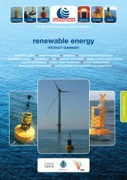
renewable energy<br />
PRODUCT SUMMARY<br />
navigation lights navigation buoys moorings remote monitoring systems<br />
· interface to SCADA fog signals AIS obstruction lights mains & solar power supplies<br />
· gps synchronisation radar target enhancers sonar transponders<br />
· installation & maintenance system design, configuration & documentation<br />
renewable energy
world-leading renewable energy solutions<br />
<strong>Hydrosphere</strong> is the <strong>UK</strong>’s leading supplier of all aids to navigation equipment for offshore renewable energy<br />
sites. We have over 18 years of experience in providing solutions ranging from single LED beacons to entire<br />
wind farm systems including: temporary solar lights, navigation buoys, navigation lights for fixed and floating<br />
structures, foghorns, remote monitoring, and data buoy platforms. Our customers include offshore wind,<br />
wave and tidal energy developers as well as Trinity House, Commissioners of Irish Lights, the Northern<br />
Lighthouse Board, and all major ports and harbours in the <strong>UK</strong> and Ireland.<br />
construction phase<br />
self contained LED navigation lights<br />
Solar-powered marine LED navigation lights for use on fixed and floating structures. All lights are able to exhibit all standard IALA flash characters.<br />
2NM lights for marking monopiles<br />
6NM beacons for temporary marking<br />
of larger structures<br />
Vega VLB-2<br />
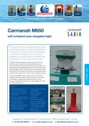
Carmanah M650<br />
Sabik SC 155<br />
Vega VLB-36 XL PP<br />
navigation buoys<br />
We are the exclusive <strong>UK</strong> and Ireland distributor for worldleading<br />
Mobilis buoys suitable for marking offshore wind farm,<br />
wave, tidal and current sites. All buoys are compliant with IALA<br />
recommendations and have options for remote monitoring with<br />
alarms via GSM or satellite.<br />
Mobilis buoys<br />
The Mobilis modular JET range of<br />
buoys range from 3.0m – 2.4m<br />
hull diameter and are suitable for<br />
offshore and deep water locations<br />
where a large, highly visible<br />
navigation buoy is required.<br />
moorings<br />
The mooring is an integral part of the system that will affect the performance and reliability of the buoy.<br />
On problematic locations we recommend a detailed mooring study be carried out to maximise reliability and<br />
minimise future maintenance costs.<br />
electronic aids to navigation<br />
sonar transponders AIS racon<br />
Sabik Sonar Transponder<br />
Kanaton AIS Transponder<br />
Type 1 and Type 3<br />
HEKLEO-SX
permanent marking<br />
signage<br />
Maintenance-free, night-time ID marking<br />
with illumination of up to 10cd/m2.<br />
fog signals and detectors<br />
Visibility detectors and 2.0NM to 0.5NM compact, omnidirectional foghorns emitting a 360 degree beam of sound.<br />
All designed for offshore use.<br />
Sabik IMS-650<br />
Sabik SFD 7100<br />
Fog detector<br />
Sabik FW 6 Fog Signal<br />
Sabik FW 1 Fog Signal<br />
LED lights<br />
5NM and 15NM marine lanterns for use on offshore wind farms and MET<br />
masts with optional GPS synchronisation.<br />
monitoring and control<br />
Remote monitoring systems by GSM or satellite for monitoring and controlling a set of fixed<br />
AtoN including: navigation lights, obstruction lights, fog signals, AIS, racons, signage, sonar<br />
transponders, two-way communication and GPS.<br />
Sabik LED 155 Sabik LED 350<br />
Sabik NavAid Controller Interface to SCADA<br />
renewable energy<br />
System design, configuration and documentation<br />
All design, configuration, documentation, supply, installation,<br />
maintenance and removal of products is available.<br />
electronic aids to navigation<br />
traffic surveillance<br />
systems<br />
radar target<br />
enhancers<br />
The products illustrated in this product summary<br />
are a sample of the range and variations available.<br />
All products can be tailored to meet site-specific<br />
requirements regarding colour, shape, navigation<br />
lights, radar reflectors, solar power supplies,<br />
monitoring systems, and moorings.<br />
Please contact us and we will be happy to guide<br />
you to the best specification for your requirements.<br />
Compliant with all IALA recommendations.<br />
Commercial<br />
Member<br />
005<br />
Sabik TSS<br />
EchoMax<br />
Active X and XS<br />
Science Technology<br />
Practice
our customers<br />
Greater Gabbard<br />
Sheringham Shoal<br />
Walney<br />
North Hoyle<br />
Scroby Sands<br />
Kentish Flats<br />
Burbo Bank<br />
Robin Rigg<br />
Lincs<br />
Strangford Lough<br />
Pelamis Wave Power <strong>Ltd</strong>.<br />
SeaGen<br />
Fred. Olsen<br />
Image courtesy of Marine Current Turbines <strong>Ltd</strong>.<br />
the right solution for the job<br />
To make sure you get the right product for your requirements consider all the factors that will affect the visibility<br />
and stability of the aid including: depth of water; sea conditions and current; lighting and range of light required;<br />
shape and topmarks; and focal plane.<br />
about <strong>Hydrosphere</strong><br />
<strong>Hydrosphere</strong> is the <strong>UK</strong>’s leading supplier of aids to navigation and has been providing cost-effective solutions to the<br />
marine industry for more than 18 years. We offer a wide range of navigation and mooring buoys, LED navigation<br />
lights, sector lights, rotating beacons, leading lights, jetty masts, beach and zone marking products and associated<br />
moorings. Rental, installation and maintenance services are also available for all our products and systems.<br />
For more information please contact us.<br />
data buoy platforms<br />
moorings<br />
navigation buoys<br />
navigation lights<br />
mooring buoys<br />
installation<br />
the <strong>UK</strong>’s leading supplier of aids to navigation<br />
aquaculture | marinas & sailing clubs | ports & harbours | offshore renewable energy | oil & gas<br />
t: +44 (0)1420 520374 www.hydrosphere.co.uk e: sales@hydrosphere.co.uk<br />
E&OE Ren_Ene_V.2.00_Sep_12
data buoy platforms<br />
moorings<br />
navigation buoys<br />
navigation lights<br />
mooring buoys<br />
installation<br />
the <strong>UK</strong>’s leading supplier of aids to navigation<br />
oil & gas<br />
PRODUCT SUMMARY<br />
NAVIGATION LIGHTS NAVIGATION BUOYS MOORINGS REMOTE MONITORING SYSTEMS<br />
FOG SIGNALS AIS OBSTRUCTION LIGHTS MAINS & SOLAR POWER SUPPLIES<br />
INSTALLATION & MAINTENANCE SYSTEM DESIGN, CONFIGURATION & DOCUMENTATION<br />
oil & gas<br />
Image by Andrew Schmidt
world-leading solutions for offshore oil & gas<br />
<strong>Hydrosphere</strong> is the <strong>UK</strong>’s leading supplier of aids to navigation offering hazardous area-approved marking for<br />
offshore oil and gas sites. We have over 18 years of experience in providing low-maintenance, high-quality<br />
equipment including navigation buoys, navigation lights for fixed and floating structures, fog signals, data<br />
buoy platforms, and remote monitoring either by GSM, satellite or AIS. Our customers include offshore oil<br />
and gas energy developers as well as all of the <strong>UK</strong> Lighthouse Authorities and major ports and harbours in<br />
the <strong>UK</strong> and Ireland.<br />
self contained LED navigation lights<br />
Solar-powered marine LED navigation lights for use on fixed and floating structures. All lights are able to exhibit all standard IALA flash characters.<br />
2NM range<br />
6NM range<br />
Vega VLB-2<br />
Carmanah M650<br />
Sabik SC 155<br />
Vega VLB-36 XL PP<br />
LED ATEX lights<br />
Explosion-proof marine LED lights suitable for ATEX sites zones 1 + 2<br />
with up to 12.5NM range at 0.74T. Non-ATEX versions also available.<br />
power systems<br />
Solar power and battery modules for hazardous areas,<br />
designed to operate in the harshest conditions.<br />
Sabik LED 155 EX<br />
Sabik LED 350 EX<br />
STSM 85 EX<br />
Solar Module<br />
SBE 130 EX Battery Box<br />
navigation buoys<br />
We offer a range of world-leading Mobilis buoys<br />
suitable for offshore applications. All buoys are<br />
compliant with IALA recommendations and have<br />
options for remote monitoring with alarms via<br />
GSM or satellite.<br />
Mobilis buoys<br />
The Mobilis modular JET buoys range from<br />
3.0m – 2.4m hull diameter and are suitable<br />
for offshore and deep water locations where<br />
a large, highly visible navigation buoy is<br />
required.<br />
moorings<br />
The mooring is an integral part of the system that will affect the performance and<br />
reliability of the buoy. On problematic locations we recommend a detailed mooring<br />
study be carried out to maximise reliability and minimise future maintenance costs.
fog signals & detectors<br />
Visibility detectors and 2.0NM to 0.5NM compact, omnidirectional foghorns emitting sound through 360°. All designed for offshore installation.<br />
Sabik SFD 7100 EX SFH 1 EX Fog Signal SFH 6 EX Fog Signal<br />
AIS<br />
Automated Identification System for broadcasting<br />
position, identity and navigation status.<br />
racon<br />
S- and X-band frequency agile racon.<br />
support structures<br />
A custom-built, self contained AtoN system for<br />
use with solar and battery power options.<br />
Kanaton AIS Transponder<br />
Type 1 and Type 3<br />
monitoring and control<br />
HEKLEO-SX<br />
Remote monitoring systems by GSM or satellite for monitoring and<br />
controlling a set of fixed AtoN including: navigation lights, obstruction<br />
lights, fog signals, AIS, racons, signage, sonar transponders, two-way<br />
communication and GPS<br />
System design, configuration and documentation<br />
All design, configuration, documentation, supply, installation,<br />
maintenance and removal of products is available.<br />
oil & gas<br />
The products illustrated in this summary are a<br />
sample of the range and variations available.<br />
All products can be tailored to meet site-specific<br />
requirements regarding colour, shape, navigation<br />
lights, solar power supplies, monitoring systems,<br />
and moorings.<br />
Please contact us and we will be happy to guide you<br />
to the best specification for your requirements.<br />
Sabik NavAid<br />
Controller<br />
Interface to SCADA<br />
Compliant with all IALA recommendations.<br />
Commercial<br />
Member<br />
005<br />
Science Technology<br />
Practice
some of our customers<br />
Trinity House<br />
Oikos Storage <strong>Ltd</strong><br />
Shell <strong>UK</strong> Oil <strong>Products</strong> <strong>Ltd</strong><br />
Veritas DGC <strong>Ltd</strong><br />
Northern Lighthouse Board<br />
Commissioners of Irish Lights<br />
Fawley Power Station<br />
Fugro Seacore<br />
Reflex Marine<br />
Peel Ports Group<br />
Ocean Power Umbilical<br />
CB&I<br />
Associated British Ports (ABP)<br />
Kingsnorth Power Station<br />
Image by Andrew Schmidt<br />
the right solution for the job<br />
To make sure you get the right system for your requirements consider all the factors that will affect the visibility and<br />
stability of the Navaid including: depth of water; sea conditions and current; environment lighting and range of light<br />
required; and focal plane.<br />
about <strong>Hydrosphere</strong><br />
<strong>Hydrosphere</strong> is the <strong>UK</strong>’s leading supplier of aids to navigation and has been providing cost-effective solutions to the<br />
marine industry for more than 18 years. We offer a wide range of navigation and mooring buoys, LED navigation<br />
lights, sector lights, rotating beacons, leading lights, jetty masts, beach and zone marking products and associated<br />
moorings. Rental, installation and maintenance services are also available for all our products and systems.<br />
For more information please contact us.<br />
data buoy platforms<br />
moorings<br />
navigation buoys<br />
navigation lights<br />
mooring buoys<br />
installation<br />
the <strong>UK</strong>’s leading supplier of aids to navigation<br />
aquaculture | marinas & sailing clubs | ports & harbours | offshore renewable energy | oil & gas<br />
t: +44 (0)1420 520374 www.hydrosphere.co.uk e: sales@hydrosphere.co.uk<br />
E&OE Oil_Gas_V.2.00_Nov_12
data buoy platforms<br />
moorings<br />
navigation buoys<br />
navigation lights<br />
mooring buoys<br />
installation<br />
the <strong>UK</strong>’s leading supplier of aids to navigation<br />
aquaculture<br />
PRODUCT SUMMARY<br />
robust and reliable solutions solar power supplies HDPE mounting plates<br />
self contained lights for sites and barges marker posts for cages<br />
radar reflectors IALA compliant buoys with topmarks<br />
aquaculture
world-leading aquaculture solutions<br />
As the <strong>UK</strong>’s leading supplier of aids to navigation, <strong>Hydrosphere</strong> have been providing robust and<br />
reliable aquaculture solutions to the marine industry for over 18 years. We provide a range of worldleading<br />
navigation lights and buoys for marking sites, as well as radar reflectors and mooring buoys.<br />
In addition, <strong>Hydrosphere</strong> design and manufacture ancillary equipment including: solar and mains<br />
power supplies, monitoring and control systems, masts and moorings, and back these up with a full<br />
installation and maintenance service.<br />
navigation lights<br />
A range of solar powered, marine LED navigation lights for use on fixed and floating structures.<br />
All lights are able to exhibit all IALA flash characters.<br />
features:<br />
• Self contained for single<br />
compact package<br />
• High performance precision<br />
optics<br />
• Cost-effective and easy<br />
to install<br />
M650<br />
Supersedes the M601 with enhanced<br />
range capability and replaceable<br />
battery pack. Used on aquaculture<br />
sites worldwide for over 10 years.<br />
Has a range of up to 2NM at 0.74T<br />
and over 200 different flash patterns.<br />
Now with optional GPS synchronisation.<br />
VLB-2<br />
An easy-to-program, high capacity<br />
marine beacon with up to 2NM<br />
performance at 0.74T and long-lasting<br />
battery. Available in red, green, white,<br />
yellow and blue, and compliant with<br />
IALA chromaticity requirements.<br />
VLB-67<br />
A high-energy efficient beacon<br />
designed for applications requiring a<br />
2 to 4NM range at 0.74T. Available as<br />
standalone, self contained and large<br />
self contained models, with optional<br />
GPS synchronisation and leading,<br />
range, and wreck options.<br />
• Low power consumption<br />
for long-lasting, consistent<br />
operation<br />
• Widespread application<br />
• Low maintenance<br />
navigation buoys<br />
A choice of 1.2m diameter buoys designed to comply with NLB and CIL recommendations and<br />
suitable for various locations from inshore mussel farms to offshore deepwater finfish sites.<br />
features:<br />
• Moulded polyethylene<br />
flotation with UV stabilisation<br />
equivalent to 15 year’s life<br />
• Suitable for a range of self<br />
contained solar lights and<br />
radar reflectors<br />
• Designed for ease of<br />
installation / maintenance<br />
M 1200<br />
T 1200<br />
moorings and shackles<br />
A lightweight, multipurpose buoy.<br />
Particularly suited for channel marking<br />
of smaller harbours, fish farms, outfalls<br />
and as special marks for marking<br />
underwater scientific instrumentation.<br />
The steel keel hull gives good stability<br />
in tidal flows and is available in several<br />
different configurations depending on<br />
site conditions.<br />
A medium-buoyancy, tailtube buoy<br />
with an integral daymark shape<br />
containing an internal radar reflector.<br />
Highly suited for use in coastal locations<br />
where conditions may be too extreme<br />
for a small, skirted buoy. A short<br />
galvanised steel tailtube and adjustable<br />
ballast weights provide a stable platform<br />
for a small self contained solar<br />
powered light.<br />
The mooring is an integral part of the<br />
system that will affect the performance<br />
and reliability of the buoy.<br />
On problematic locations we<br />
recommend a detailed mooring study<br />
be carried out to maximise reliability<br />
and minimise future maintenance costs.<br />
A range of chain and shackle supplies<br />
are available.<br />
• Modular system to reduce<br />
spares holding<br />
• M 1200 available with<br />
standard, upright storage,<br />
low draft and high current<br />
keel options
adar reflectors<br />
A range of active-passive radar reflectors and target enhancers for marine use.<br />
ECHOMAX 230<br />
Midi Basemount<br />
Suitable for navigation buoys and displacement hulls<br />
with speeds up to 15 knots. Features four integrally<br />
moulded fixing points for stability and reliability.<br />
ECHOMAX 305 FPMS<br />
High response radar reflector particularly suitable for<br />
navigation buoys. Built with a robust 3mm thick case<br />
with a flat top and base with customised fittings<br />
at either end.<br />
Active-X Band and XS Dual Band<br />
Radar Target Enhancers<br />
Receives a signal from transmitting radar, amplifies it<br />
and returns a stronger signal to help alert oncoming<br />
vessels of its position.<br />
marker posts and crosses<br />
The M650, VLB-2 and VLB-67 can be easily fixed onto a 2.4m<br />
tall marker post mounted to a fish cage.<br />
HDPE mounting plate<br />
Designed for rail, pole and wall mounting including aquaculture farms,<br />
masts and poles, and wind farm harbour walls.<br />
Available with 3 sizes of St Andrew’s Cross topmark or with a Herikon<br />
Polyurethane topmark.<br />
Available as standard or with U bolts, nuts and washers to suit either<br />
50mm or 76mm diameter tubing.<br />
aquaculture<br />
barge light<br />
M650 navigation light with optional sector plate<br />
for Port, Starboard and Stern lighting.<br />
The products illustrated in this summary are a<br />
sample of the range and variations available.<br />
All aquaculture solutions can be tailored to<br />
meet user requirements. Please contact us<br />
and we will be happy to guide you to the best<br />
specification for your need.<br />
Compliant with all IALA recommendations.<br />
Commercial<br />
Member<br />
M650<br />
Available in Green (Starboard), Red (Port) and White (Stern).<br />
005<br />
Science Technology<br />
Practice
specifications and applications<br />
navigation lights<br />
Light<br />
Max Night Range<br />
(NM at 0.74T)<br />
Solar Powered Input Power 12v dc<br />
Input Power<br />
110-240v ac<br />
Optional<br />
Synchronisation<br />
Buoy/Cage<br />
Barge<br />
Vega VLB-2 2 √ √ √<br />
Carmanah M650 2 √ √ √ √<br />
Vega VLB-67 4 √ √ √ √ √ √<br />
navigation buoys<br />
Buoy<br />
Diameter m<br />
Mass Kg<br />
Max Ballast Kg<br />
Max Kg<br />
Gross<br />
Buoyancy Kg<br />
Reserve<br />
Buoyancy Kg<br />
Inshore<br />
Estuary<br />
Coastal<br />
Focal Plane m<br />
Chain mm<br />
Sinker Kg<br />
T 1200 1.2 100 50 150 835 610 √ √ √ 1.5 10 - 20 1000 - 1500<br />
M 1200 1.2 85 N/A 85 380 295 √ √ 1.5 10 - 20 500 - 1000<br />
the right product for the job<br />
To make sure you get the right solution for your requirements consider all the factors that will affect the visibility and<br />
stability of the mark including: depth of water; sea conditions and current; lighting and range of light required; shape<br />
and topmarks; and focal plane.<br />
about <strong>Hydrosphere</strong><br />
<strong>Hydrosphere</strong> is the <strong>UK</strong>’s leading supplier of aids to navigation and has been providing cost-effective solutions to the<br />
marine industry for more than 18 years. We offer a wide range of navigation and mooring buoys, LED navigation<br />
lights, sector lights, rotating beacons, leading lights, jetty masts, beach and zone marking products and associated<br />
moorings. Rental, installation and maintenance services are also available for all our products and systems.<br />
For more information please contact us.<br />
data buoy platforms<br />
moorings<br />
navigation buoys<br />
navigation lights<br />
mooring buoys<br />
installation<br />
the <strong>UK</strong>’s leading supplier of aids to navigation<br />
aquaculture | marinas & sailing clubs | ports & harbours | offshore renewable energy | oil & gas<br />
t: +44 (0)1420 520374 www.hydrosphere.co.uk e: sales@hydrosphere.co.uk<br />
E&OE Aqu_V.2.00_Jul_12
data buoy platforms<br />
moorings<br />
navigation buoys<br />
navigation lights<br />
mooring buoys<br />
installation<br />
the <strong>UK</strong>’s leading supplier of aids to navigation<br />
installation &<br />
maintenance services<br />
a complete, compliant solution<br />
Following a detailed discussion to establish the most effective<br />
system for your requirement, <strong>Hydrosphere</strong> are able to deliver a<br />
complete Aids to Navigation solution from initial design and supply<br />
of the aid, right through to deployment and ongoing maintenance.<br />
Where necessary, this can include a detailed site study for<br />
problematic locations and the construction of bespoke products at<br />
our warehouse for unique applications. All of our solutions are fully<br />
compliant with IALA recommendations.<br />
delivery, deployment and installation<br />
We can test and install your Aid to Navigation for you to ensure it<br />
is safely and effectively deployed. We have deployed buoys and<br />
lights for a number of ports, harbours and renewable wind farms<br />
including: ABP, Grimsby, Argyle and Bute Council, Blackwall East<br />
Estates, British Waterways, Canterbury City Council, Centric<br />
Renewable Energy, Shoreham Harbour, Newhaven Harbour, Port of<br />
London, Poole Harbour Commissioning, Sovereign Harbour, Fowey<br />
Harbours, Sheringham Shoal and Greater Gabbard.<br />
installation & maintenance<br />
maintenance and servicing<br />
Even with long-lasting applications, regular maintenance checks<br />
can greatly prolong the service of your Aid to Navigation, power<br />
supply and ancillary equipment. We offer a choice of scheduled<br />
and ad-hoc maintenance services carried out by qualified engineers<br />
for all fixed and floating applications.<br />
In addition, we have a team of engineers on hand to respond<br />
to emergency repairs, buoy and beacon casualties, or simply to<br />
support maintenance, replacement and removal work.<br />
aquaculture | marinas & sailing clubs | ports & harbours | offshore renewable energy | oil & gas<br />
t: +44 (0)1420 520374 www.hydrosphere.co.uk e: sales@hydrosphere.co.uk
installation &<br />
maintenance services<br />
a full installation and maintenance<br />
service can include:<br />
» Lifting of all buoys and moorings, including sinker, to deck<br />
» Cleaning and high-pressure water jetting<br />
» Cleaning and inspection of lights to ensure<br />
correct operation<br />
» Inspection of power supply<br />
» Inspection of topmarks<br />
» Inspection of moorings and lifting eyes<br />
» Inspection of shackles and bridle<br />
» Deployment of buoy in assigned position with<br />
confirmation of correct positioning within 5m using DGPS<br />
» Monthly reports with daily records obtained from<br />
automatic monitoring systems if mounted on the buoys<br />
about <strong>Hydrosphere</strong><br />
<strong>Hydrosphere</strong> is the <strong>UK</strong>’s leading supplier of aids to navigation and has been providing cost-effective solutions to the<br />
marine industry for more than 18 years. We offer a wide range of navigation and mooring buoys, LED navigation<br />
lights, sector lights, rotating beacons, leading lights, jetty masts, beach and zone marking products and associated<br />
moorings. Rental, installation and maintenance services are available for all our products and systems.<br />
For more information please contact us.<br />
data buoy platforms | moorings | navigation buoys | navigation lights | mooring buoys | installation<br />
t: +44 (0)1420 520374<br />
www.hydrosphere.co.uk<br />
e: sales@hydrosphere.co.uk<br />
Compliant with all IALA recommendations.<br />
Commercial<br />
Member<br />
005<br />
E&OE Ins_Mai_V.2.00_Jul_2012<br />
Word mark based on GillSans Light typeface<br />
Pantone 187 C<br />
Science Technology<br />
Practice<br />
Pantone 166 C
data buoy platforms<br />
moorings<br />
navigation buoys<br />
navigation lights<br />
mooring buoys<br />
installation<br />
the <strong>UK</strong>’s leading supplier of aids to navigation<br />
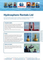
<strong>Hydrosphere</strong> Rentals <strong>Ltd</strong><br />
As the <strong>UK</strong>’s leading supplier of aids to navigation, <strong>Hydrosphere</strong> Rentals <strong>Ltd</strong> provides<br />
high quality and cost-effective lights, buoys, chains and sinkers for rental.<br />
navigation lights<br />
<strong>Hydrosphere</strong> Rentals <strong>Ltd</strong> offers a range of marine navigation lights<br />
to rent for use on a variety of navigation buoys and data buoy<br />
platforms. Representing world-renowned innovators in marine<br />
technology – Vega, Carmanah and Sabik – <strong>Hydrosphere</strong> provides high<br />
performance, standalone and self contained solar powered LED lights<br />
that range from 1-5NM.<br />
All lights are able to exhibit all standard IALA flash characters.<br />
buoys<br />
<strong>Hydrosphere</strong> is the exclusive <strong>UK</strong> and Ireland distributor for worldleading<br />
buoy manufacturer Mobilis. We offer a range of navigation<br />
buoys and data buoy platforms to rent in a variety of sizes and<br />
configurations, from 3.0m to 1.2m hull diameter.<br />
All Mobilis buoys have a unique modular design and are constructed<br />
from UV stabilised medium density polyethylene (MDPE), making them<br />
easy to transport and greatly reducing the need for maintenance,<br />
inspection and spares holding for longer periods of rental.<br />
© <strong>UK</strong> Met Office<br />
<strong>Hydrosphere</strong> Rentals <strong>Ltd</strong><br />
sinkers & chains<br />
Robust, cast-iron sinkers weighing from 500Kg to 5 tons and a<br />
selection of chains, swivels and shackles are available to suit all<br />
our products for rent. We will be happy to guide you on the right<br />
solution for your specification.<br />
aquaculture | marinas & sailing clubs | ports & harbours | offshore renewable energy | oil & gas<br />
t: +44 (0)1420 520374 www.hydrosphererentals.co.uk e: sales@hydrosphererentals.co.uk
<strong>Hydrosphere</strong> Rentals <strong>Ltd</strong><br />
specifications & applications<br />
buoys<br />
Buoy Dia. m Mass Kg Max Ballast Kg Max Kg<br />
JET 9000 QI<br />
HV-PF4<br />
JET 7000 QI<br />
HV-PF3<br />
JET 2500 Q<br />
PF2.5<br />
JET 2000 J<br />
PF2.5<br />
Gross<br />
Buoyancy Kg<br />
Reserve<br />
Buoyancy Kg<br />
Inshore Estuary Coastal Offshore Chain mm Sinker Kg<br />
3.0 2100 500 2600 9000 6400 √ √ √ √ 30 - 38 3000 +<br />
2.6 1750 500 2250 7000 4750 √ √ √ √ 30 - 38 3000 +<br />
1.9 750 200 950 2500 1550 √ √ √ √ 20 - 25 2000 - 3000<br />
1.9 650 160 810 2000 1190 √ √ √ 20 - 25 2000 - 3000<br />
T 1200 1.2 100 50 150 835 610 √ √ √ 10 - 20 1000 - 1500<br />
DB 8000 3.0 2140 - - 8000 - √ 30 - 38 3000 +<br />
DB 2000 1.9 910 - - 2000 - √ √ √ 20 - 25 2000 - 3000<br />
DB 650 1.2 135 - - 650 - √ √ 10 - 20 1000 - 1500<br />
navigation lights<br />
Light<br />
Max Range<br />
(NM at 0.74T)<br />
Solar Powered<br />
Input Power<br />
12v dc<br />
Optional<br />
Synchronisation<br />
All-round<br />
Suitable Buoy<br />
Vega VLB-2 2 √ √ √ T 1200, DB 650<br />
Carmanah M650 2 √ √ √ T 1200, DB 650<br />
Vega VLB-67 SS 4 √ √ √ JET 2500, JET 2000, DB 2000<br />
Vega VLB-36 SA 6 √ √ √ JET 9000, JET 7000, DB 8000<br />
Vega VLB-36 XL 6 √ √ √ JET 9000, JET 7000, DB 8000<br />
chains<br />
38mm - suitable for the<br />
JET 9000, JET 7000 and DB 8000<br />
26mm - suitable for the<br />
JET 2500, JET 2000 and DB 2000<br />
16mm - suitable for the T 1200<br />
and DB 650<br />
All chains are available in lengths<br />
of approximately 27m.<br />
Guidelines only. See individual product datasheets for full specifications.<br />
the right navigation aid for the job<br />
To make sure you get the right solution for your requirements consider all of the factors that will affect the visibility<br />
and stability of the aid including: the depth of water; sea conditions and current; lighting and range of light required;<br />
shape and topmarks; and focal plane.<br />
about <strong>Hydrosphere</strong><br />
<strong>Hydrosphere</strong> is the <strong>UK</strong>’s leading supplier of aids to navigation and has been providing cost-effective solutions to the marine<br />
industry for more than 18 years. We offer a wide range of navigation and mooring buoys, LED navigation lights, sector lights,<br />
rotating beacons, leading lights, jetty masts, beach and zone marking products and associated moorings. Rental, installation and<br />
maintenance services are also available for all our products and systems.<br />
For more information please contact us.<br />
data buoy platforms | moorings | navigation buoys | navigation lights | mooring buoys | installation<br />
t: +44 (0)1420 520374<br />
www.hydrosphererentals.co.uk<br />
e: sales@hydrosphererentals.co.uk<br />
Compliant with all IALA recommendations.<br />
Commercial<br />
Member<br />
005<br />
E&OE Hyd_Ren_ V.2.00_Nov_12<br />
Word mark based on GillSans Light typeface<br />
Pantone 187 C<br />
Science Technology<br />
Practice<br />
Pantone 166 C
data buoy platforms<br />
moorings<br />
navigation buoys<br />
navigation lights<br />
mooring buoys<br />
installation<br />
the <strong>UK</strong>’s leading supplier of aids to navigation<br />
navigation buoys<br />
PRODUCT SUMMARY<br />
Lateral Cardinal Special Mark Isolated Danger<br />
Safe Water Wreck Inshore Estuary Offshore<br />
High Current Spar Beach Markers<br />
navigation buoys
world-leading navigation buoys<br />
<strong>Hydrosphere</strong> is the <strong>UK</strong>’s leading supplier of aids to navigation and the exclusive <strong>UK</strong> and Ireland<br />
distributor for world-leading buoy manufacturer Mobilis. A comprehensive range of Mobilis buoys are<br />
available across a variety of sizes and configurations, from 3m to 0.4m hull diameter.<br />
3m diameter range<br />
Available as Intermediate Tailtube (QI), Long Tailtube (QL), or Skirted (J)<br />
2.6m diameter range<br />
Available as Intermediate Tailtube (QI), Long Tailtube (QL), or Skirted (J)<br />
JET 9000 JET 9000 JET 8000 J<br />
JET 7000<br />
JET 7000<br />
JET 5700 J<br />
2.4m diameter range<br />
Available with Intermediate Tailtube (QI), Long Tailtube (QL),<br />
Flat Bottom (FB), or Skirted (J)<br />
2m diameter range<br />
Available with Tailtube (Q), Flat Bottom (FB), or Skirted (J)<br />
JET 5000<br />
JET 5000 JET 4000 J<br />
JET 2500 FB JET 2500<br />
JET 2000 J<br />
buoy configurations<br />
A range of modular towers are available for optional daymarks. For larger buoys the high visibility (HV) towers provide a visual<br />
shape with ample space for solar panels and batteries where longer range lights or additional electronic systems are required.<br />
Cardinal Lateral<br />
Special Mark<br />
Safe Water<br />
Isolated Danger Wreck
1.24m diameter range<br />
Available with Tailtube (Q) or Flat Bottom (FB)<br />
1.2m diameter range<br />
Available with standard, upright storage, low draft,<br />
and high current keel options<br />
AQ 1500 BC 1242 FB 1242<br />
T 1200<br />
M 1200 M 1200<br />
other markers<br />
Top mark with<br />
radar reflector<br />
Self contained light<br />
Top mark support<br />
Safety ring<br />
Aluminium tower<br />
spar buoys<br />
trackless<br />
zone marking<br />
Non-slip deck<br />
Mooring point<br />
Galvanised steel<br />
central structure<br />
Lifting points<br />
Anode<br />
Float<br />
navigation buoys<br />
Mooring point<br />
adaptable<br />
• Exchangeable interfaces<br />
• Multiple sizes and heights<br />
• Variable buoyancy<br />
and weight<br />
• Commonality of parts<br />
durable<br />
• Galvanised steel<br />
central structure<br />
• Moulded polyethylene<br />
flotation with UV<br />
stabilisation equivalent to<br />
15 year’s life<br />
• Appearance easily<br />
maintained through<br />
pressure washing<br />
lightweight<br />
• Easy to assemble<br />
• Quick to deploy<br />
• Cost-effective to repair<br />
and maintain<br />
• 2-3 times lighter than steel<br />
safe<br />
• Self-contained waterproof<br />
compartments<br />
• Individually replaceable<br />
parts<br />
• Non-slip area and<br />
foot lock<br />
Ballast weight<br />
Shackle<br />
The buoys illustrated in this product summary are a<br />
sample of the range and variations available. All buoys<br />
can be tailored to meet user requirements regarding<br />
colour, shape, navigation lights, radar reflectors, solar<br />
power supplies, monitoring systems, and moorings.<br />
Full installation and maintenance services are available.<br />
Compliant with all IALA recommendations.<br />
Commercial<br />
Member<br />
005<br />
Science Technology<br />
Practice
specifications and applications<br />
Buoy Dia. m Mass Kg Max Ballast Kg Max Kg<br />
Gross<br />
Buoyancy Kg<br />
Reserve<br />
Buoyancy Kg<br />
Inshore Estuary Coastal Offshore Chain mm Sinker Kg<br />
JET 9000 QI /QL 3.0 2100 500 2600 9000 6400 √ √ √ √ 30 - 38 3000 +<br />
JET 8000 J 3.0 2000 400 2400 8000 5600 √ √ √ √ 30 - 38 3000 +<br />
JET 7000 QI /QL 2.6 1750 500 2250 7000 4750 √ √ √ √ 30 - 38 3000 +<br />
JET 5700 J 2.6 2000 400 2400 5700 3300 √ √ √ √ 30 - 38 3000 +<br />
JET 5000 QI / QL 2.4 1450 400 1850 5000 3150 √ √ √ √ 25 - 32 3000 +<br />
JET 5000 FB 2.4 1260 250 1510 5000 3490 √ √ √ 25 - 32 3000 +<br />
JET 4000 J 2.4 1250 400 1650 4000 2350 √ √ √ 25 - 32 3000 +<br />
JET 2500 Q 1.9 750 200 950 2500 1550 √ √ √ √ 20 - 25 2000 - 3000<br />
JET 2500 FB 1.9 750 N/A 750 2500 1750 √ √ √ 20 - 25 2000 - 3000<br />
JET 2000 J 1.9 650 160 810 2000 1190 √ √ √ 20 - 25 2000 - 3000<br />
AQ 1500 1.24 500 150 650 1500 850 √ √ √ 16 - 25 1000 - 2000<br />
BC 1242 1.24 380 100 480 900 420 √ √ √ 16 - 25 1000 - 2000<br />
FB 1242 1.24 270 N/A 270 900 630 √ √ √ 16 - 25 1000 - 2000<br />
T 1200 1.2 100 50 150 835 610 √ √ √ 10 - 20 1000 - 1500<br />
M 1200 1.2 85 N/A 85 380 295 √ √ 10 - 20 500 - 1000<br />
SP 1200 1.2 500 600 1100 2500 1400 √ √ √ √ 20 - 25 Site dependent<br />
SP 900 0.9 270 400 670 1700 1030 √ √ √ 16 - 25 Site dependent<br />
SP 630 0.63 200 120 320 420 100 √ √ 16 - 25 Site dependent<br />
ES 1700 0.4 31 N/A 31 234 203 √ √ √ 8 - 16 150 +<br />
ES 450 0.45 46 35 81 235 119 √ √ 14 - 20 Site dependent<br />
Trackless 0.9 x 2.0 65 N/A 65 √ √ 8 - 16 1000 +<br />
Guidelines only. See individual product datasheets for full specifications.<br />
the right buoy for the job<br />
To make sure you get the right buoy for your<br />
requirements consider all the factors that will affect the<br />
visibility and stability of the mark including: depth of<br />
water; sea conditions and current; lighting and range of<br />
light required; shape and topmarks; and focal plane.<br />
mooring tips:<br />
The mooring is an integral part of the system that will<br />
affect the performance and reliability of the buoy.<br />
On problematic locations we recommend a detailed<br />
mooring study be carried out to maximise reliability<br />
and minimise future maintenance costs.<br />
about <strong>Hydrosphere</strong><br />
<strong>Hydrosphere</strong> is the <strong>UK</strong>’s leading supplier of aids to navigation and has been providing cost-effective solutions to the<br />
marine industry for more than 18 years. We offer a wide range of navigation and mooring buoys, LED navigation<br />
lights, sector lights, rotating beacons, leading lights, jetty masts, beach and zone marking products and associated<br />
moorings. Rental, installation and maintenance services are also available for all our products and systems.<br />
For more information please contact us.<br />
data buoy platforms<br />
moorings<br />
navigation buoys<br />
navigation lights<br />
mooring buoys<br />
installation<br />
the <strong>UK</strong>’s leading supplier of aids to navigation<br />
aquaculture | marinas & sailing clubs | ports & harbours | offshore renewable energy | oil & gas<br />
t: +44 (0)1420 520374 www.hydrosphere.co.uk e: sales@hydrosphere.co.uk<br />
E&OE Nav_Buo_V.2.00_Aug_12
data buoy platforms<br />
moorings<br />
navigation buoys<br />
navigation lights<br />
mooring buoys<br />
installation<br />
the <strong>UK</strong>’s leading supplier of aids to navigation<br />
Mobilis JET 9000 QI/QL<br />
& JET 8000 J<br />
3m diameter navigation buoys<br />
The JET 9000 and JET 8000, with 3.0m diameter<br />
hulls providing up to 9000Kg of buoyancy, are the<br />
largest buoys in the JET series. They are suitable for<br />
use in offshore and deepwater locations where a<br />
highly visible navigation buoy is required.<br />
Built as an alternative to GLA Class 1 or 2 steel buoys with respect<br />
to visibility, focal height and sea-keeping qualities, the buoy has<br />
longer maintenance intervals, is much lighter and easier to handle,<br />
and can therefore be maintained using smaller vessels.<br />
The JET 9000 is available with intermediate tailtube (QI) and long<br />
tailtube (QL) options and the JET 8000 is skirted (J). The tailtube<br />
options provide a high focal plane of up to 6m whilst the skirted<br />
version can achieve heights of 4m.<br />
The buoys are all constructed around a galvanised steel central<br />
structure and use 4 medium density polyethylene (MDPE) hull<br />
floats, with marine grade aluminium tower and topmark assemblies.<br />
The buoys’ modular design allows for commonality of parts,<br />
thereby reducing maintenance, inspection, replacement and spares<br />
holding costs.<br />
navigation buoys<br />
features:<br />
• UV stabilised MDPE<br />
components – retains colour<br />
within IALA guidelines for<br />
more than 15 years<br />
• Focal height of up to 6m<br />
• Modular system - reduces<br />
spares holding<br />
• Multiple mooring configurations<br />
including high current capability<br />
• Interchangeable parts<br />
• Built-in safety features such<br />
as hand-holds, ladders and<br />
non-slip deck<br />
• Open tower structure<br />
provides easy and safe<br />
access for maintenance<br />
buoy configurations<br />
Cardinal<br />
Lateral<br />
Special Mark<br />
Safe Water Isolated Danger<br />
aquaculture | marinas & sailing clubs | ports & harbours | offshore renewable energy | oil & gas<br />
t: +44 (0)1420 520374 www.hydrosphere.co.uk e: sales@hydrosphere.co.uk
Mobilis JET 9000 QI/QL<br />
& JET 8000 J<br />
specifications and applications<br />
JET 9000 QL<br />
(with high visibility tower)<br />
JET 9000 QI<br />
construction<br />
Central Structure<br />
Galvanised steel<br />
Hull<br />
MDPE (4 float sections)<br />
Tower, Topmark & Radar Reflector Marine grade aluminium<br />
Daymark<br />
MDPE<br />
physical JET 9000 JET 8000<br />
6475<br />
Diameter m 3.0 3.0<br />
Mass Kg 2100 2000<br />
Max Ballast Kg 500 400<br />
Max Kg 2600 2400<br />
Gross Buoyancy Kg 9000 8000<br />
Reserve Buoyancy Kg 6400 5600<br />
Focal Plane m Up to 6m Up to 4.3m<br />
Draft m<br />
QI QL<br />
3.0 5.1<br />
1.6<br />
Overall Height m (exc. topmark) 9.5 11.5 6.0<br />
application<br />
10496<br />
2888<br />
JET 8000 J<br />
Ø3000<br />
1153<br />
Inshore<br />
Estuary<br />
Coastal<br />
Offshore<br />
√<br />
√<br />
√<br />
√<br />
5952<br />
4325<br />
mooring<br />
Type<br />
Single Point / Bridle<br />
Chain mm 30 - 38<br />
Sinker Kg 3000 +<br />
1595<br />
1037<br />
Ø3000<br />
the right buoy for the job<br />
To make sure you get the right buoy for your<br />
requirements consider all the factors that will affect the<br />
visibility and stability of the mark including: depth of<br />
water; sea conditions and current; lighting and range of<br />
light required; shape and topmarks; and focal plane.<br />
mooring tips:<br />
The mooring is an integral part of the system that will<br />
affect the performance and reliability of the buoy.<br />
On problematic locations we recommend a detailed<br />
mooring study be carried out to maximise reliability<br />
and minimise future maintenance costs.<br />
about <strong>Hydrosphere</strong><br />
<strong>Hydrosphere</strong> is the <strong>UK</strong>’s leading supplier of aids to navigation and has been providing cost-effective solutions to the marine<br />
industry for more than 18 years. We offer a wide range of navigation and mooring buoys, LED navigation lights, sector lights,<br />
rotating beacons, leading lights, jetty masts, beach and zone marking products and associated moorings. Rental, installation and<br />
maintenance services are also available for all our products and systems.<br />
For more information please contact us.<br />
data buoy platforms | moorings | navigation buoys | navigation lights | mooring buoys | installation<br />
t: +44 (0)1420 520374<br />
www.hydrosphere.co.uk<br />
e: sales@hydrosphere.co.uk<br />
Compliant with all IALA recommendations.<br />
Commercial<br />
Member<br />
005<br />
E&OE JET_9000_V.2.00_Jul_12<br />
Word mark based on GillSans Light typeface<br />
Pantone 187 C<br />
Science Technology<br />
Practice<br />
Pantone 166 C
data buoy platforms<br />
moorings<br />
navigation buoys<br />
navigation lights<br />
mooring buoys<br />
installation<br />
the <strong>UK</strong>’s leading supplier of aids to navigation<br />
Mobilis JET 7000 QI/QL<br />
& JET 5700 J<br />
2.6m diameter navigation buoys<br />
The JET 7000 and JET 5700 are the second largest<br />
buoys in the JET series with 2.6m diameter hulls<br />
providing up to 7000Kg of buoyancy. They are<br />
suitable for use in offshore, deepwater and river<br />
locations where high visibility is required.<br />
The JET 7000 is available with intermediate tailtube (QI) and long<br />
tailtube (QL) options and the JET 5700 is skirted (J). The tailtube<br />
options provide a high focal plane of up to 6m whilst the skirted<br />
buoy has a focal height of up to 4m.<br />
All JET 7000 and JET 5700 buoys are constructed around a<br />
galvanised steel central structure and use medium density<br />
polyethylene (MDPE) hull floats. Tower and topmark assemblies are<br />
made from marine grade aluminium. The buoys’ modular design<br />
allows for commonality of parts, thereby reducing maintenance,<br />
inspection, replacement and spares holding costs. The result is a<br />
buoy that has longer maintenance intervals, can be maintained<br />
using small vessels, and therefore offers a convenient, lightweight<br />
alternative to traditional GLA Class 2 steel buoys.<br />
navigation buoys<br />
features:<br />
• UV stabilised MDPE<br />
components – retains colour<br />
within IALA guidelines for<br />
more than 15 years<br />
• High size to weight ratio<br />
• Modular system - reduces<br />
spares holding<br />
• Multiple mooring configurations<br />
including high current capability<br />
• Wide range of navigation<br />
lights accepted<br />
• Suitable for radar reflectors<br />
and racon<br />
• Built-in safety features such<br />
as non-slip deck<br />
• Can be tailored to meet<br />
individual requirements for<br />
navigation lights, solar panels<br />
and battery configurations<br />
buoy configurations<br />
Cardinal<br />
Lateral<br />
Special Mark<br />
Safe Water Isolated Danger<br />
aquaculture | marinas & sailing clubs | ports & harbours | offshore renewable energy | oil & gas<br />
t: +44 (0)1420 520374 www.hydrosphere.co.uk e: sales@hydrosphere.co.uk
Mobilis JET 7000 QI/QL<br />
& JET 5700 J<br />
specifications and applications<br />
JET 7000 QL<br />
JET 7000 QI<br />
construction<br />
Central Structure<br />
Hull<br />
Tower, Topmark & Radar Reflector<br />
Daymark<br />
Galvanised steel<br />
MDPE (4 float sections)<br />
Marine grade aluminium<br />
MDPE<br />
6370<br />
physical JET 7000 JET 5700<br />
10514<br />
Diameter m 2.6 2.6<br />
Mass Kg 1750 2000<br />
Max Ballast Kg 500 400<br />
Max Kg 2250 2400<br />
Gross Buoyancy Kg 7000 5700<br />
Reserve Buoyancy Kg 4750 3300<br />
Focal Plane m<br />
QI QL<br />
6.0 6.4<br />
4.0<br />
Draft m 3.0 5.1 1.7<br />
Overall Height m (exc. topmark) 9.0 11.5 7.0<br />
application<br />
2996<br />
Ø2600<br />
JET 5700 J<br />
1029<br />
Inshore<br />
Estuary<br />
Coastal<br />
Offshore<br />
√<br />
√<br />
√<br />
√<br />
7095<br />
4260<br />
mooring<br />
909<br />
Type<br />
Single Point / Bridle<br />
Chain mm 30 - 38<br />
Sinker Kg 3000 +<br />
1687<br />
Ø2600<br />
the right buoy for the job<br />
To make sure you get the right buoy for your<br />
requirements consider all the factors that will affect the<br />
visibility and stability of the mark including: depth of<br />
water; sea conditions and current; lighting and range of<br />
light required; shape and topmarks; and focal plane.<br />
mooring tips:<br />
The mooring is an integral part of the system that will<br />
affect the performance and reliability of the buoy.<br />
On problematic locations we recommend a detailed<br />
mooring study be carried out to maximise reliability<br />
and minimise future maintenance costs.<br />
about <strong>Hydrosphere</strong><br />
<strong>Hydrosphere</strong> is the <strong>UK</strong>’s leading supplier of aids to navigation and has been providing cost-effective solutions to the marine<br />
industry for more than 18 years. We offer a wide range of navigation and mooring buoys, LED navigation lights, sector lights,<br />
rotating beacons, leading lights, jetty masts, beach and zone marking products and associated moorings. Rental, installation and<br />
maintenance services are also available for all our products and systems.<br />
For more information please contact us.<br />
data buoy platforms | moorings | navigation buoys | navigation lights | mooring buoys | installation<br />
t: +44 (0)1420 520374<br />
www.hydrosphere.co.uk<br />
e: sales@hydrosphere.co.uk<br />
Compliant with all IALA recommendations.<br />
Commercial<br />
Member<br />
005<br />
E&OE JET_7000_V.2.00_Jul_12<br />
Word mark based on GillSans Light typeface<br />
Pantone 187 C<br />
Science Technology<br />
Practice<br />
Pantone 166 C
data buoy platforms<br />
moorings<br />
navigation buoys<br />
navigation lights<br />
mooring buoys<br />
installation<br />
the <strong>UK</strong>’s leading supplier of aids to navigation<br />
Mobilis JET 5000 QI/QL/FB<br />
& JET 4000 J<br />
2.4m diameter navigation buoys<br />
The JET 5000 and JET 4000 are the third largest<br />
buoys in the JET series with a 2.4m diameter hull<br />
that provides up to 5000Kg of buoyancy. They are<br />
suitable for use in offshore, deepwater and large<br />
river applications where high visibility is required.<br />
The JET 5000 is available with intermediate tailtube (QI), long tailtube<br />
(QL) or flat bottom (FB) options and the JET 4000 is skirted (J).<br />
The tailtube options provide a high focal plane whilst the flat bottom<br />
is suitable for use in shallow and fast water, particularly where there<br />
is a risk of grounding.<br />
The buoys are constructed around a galvanised steel central<br />
structure with marine grade aluminium tower and topmark<br />
assemblies and medium density polyethylene (MDPE) hull floats.<br />
The buoys’ modular design allows for commonality of parts to reduce<br />
maintenance, inspection, replacement and spares holding costs.<br />
The buoys are also much lighter and therefore easier to handle than<br />
traditional GLA Class 2 steel buoys, and they can be maintained<br />
using smaller vessels.<br />
navigation buoys<br />
features:<br />
• UV stabilised MDPE<br />
components - retains colour<br />
for more than 15 years<br />
• Modular system - reduces<br />
spares holding<br />
• Highly stable with focal plane<br />
of up to 6m<br />
• Multiple mooring configurations<br />
including high current capability<br />
• Wide range of navigation<br />
lights accepted<br />
• Suitable for radar reflectors<br />
and racon<br />
• Flat bottom option for shallow<br />
water applications<br />
• Built-in safety features such<br />
as a non-slip deck<br />
buoy configurations<br />
Cardinal<br />
Lateral<br />
Special Mark<br />
Safe Water Isolated Danger<br />
aquaculture | marinas & sailing clubs | ports & harbours | offshore renewable energy | oil & gas<br />
t: +44 (0)1420 520374 www.hydrosphere.co.uk e: sales@hydrosphere.co.uk
Mobilis JET 5000 QI/QL/FB<br />
& JET 4000 J<br />
specifications and applications<br />
construction<br />
JET 5000 QL<br />
JET 5000 QI<br />
(with high visibility tower)<br />
Central Structure<br />
Galvanised steel<br />
Hull<br />
MDPE (4 float sections)<br />
Tower / Daymark<br />
Marine grade aluminium<br />
Topmark & Radar Reflector<br />
Marine grade aluminium<br />
physical 5000 QI/QL 5000 FB 4000 J<br />
Diameter m 2.4 2.4 2.4<br />
Mass Kg 1450 1260 1250<br />
Max Ballast Kg 400 250 400<br />
Max Kg 1850 1510 1650<br />
Gross Buoyancy Kg 5000 5000 4000<br />
Reserve Buoyancy Kg 3150 3490 2350<br />
Max Focal Plane m<br />
QI QL<br />
5.0 6.0<br />
3.4 3.2<br />
Draft m 2.6 4.5 1.0 1.3<br />
Overall Height m<br />
(exc. topmark)<br />
8.9 11.7 5.5 5.6<br />
application<br />
7273<br />
4470<br />
6145<br />
849<br />
Ø2400<br />
JET 4000 J<br />
7173<br />
3000<br />
Ø2400<br />
JET 5000 FB<br />
1480<br />
850<br />
2102<br />
Inshore<br />
Estuary<br />
Coastal<br />
Offshore<br />
mooring<br />
Type<br />
Single Point / Bridle<br />
Chain mm 25 - 32<br />
Sinker Kg 3000 +<br />
√<br />
√<br />
√<br />
√ (QI and QL)<br />
5665<br />
1345 3198<br />
Ø2400<br />
854<br />
5507<br />
990 3395<br />
Ø2400<br />
990<br />
the right buoy for the job<br />
To make sure you get the right buoy for your<br />
requirements consider all the factors that will affect the<br />
visibility and stability of the mark including: depth of<br />
water; sea conditions and current; lighting and range of<br />
light required; shape and topmarks; and focal plane.<br />
mooring tips:<br />
The mooring is an integral part of the system that will<br />
affect the performance and reliability of the buoy.<br />
On problematic locations we recommend a detailed<br />
mooring study be carried out to maximise reliability<br />
and minimise future maintenance costs.<br />
about <strong>Hydrosphere</strong><br />
<strong>Hydrosphere</strong> is the <strong>UK</strong>’s leading supplier of aids to navigation and has been providing cost-effective solutions to the marine<br />
industry for more than 18 years. We offer a wide range of navigation and mooring buoys, LED navigation lights, sector lights,<br />
rotating beacons, leading lights, jetty masts, beach and zone marking products and associated moorings. Rental, installation and<br />
maintenance services are also available for all our products and systems.<br />
For more information please contact us.<br />
data buoy platforms | moorings | navigation buoys | navigation lights | mooring buoys | installation<br />
t: +44 (0)1420 520374<br />
www.hydrosphere.co.uk<br />
e: sales@hydrosphere.co.uk<br />
Compliant with all IALA recommendations.<br />
Commercial<br />
Member<br />
005<br />
E&OE JET_5000_V.2.00_Jul_12<br />
Word mark based on GillSans Light typeface<br />
Pantone 187 C<br />
Science Technology<br />
Practice<br />
Pantone 166 C
data buoy platforms<br />
moorings<br />
navigation buoys<br />
navigation lights<br />
mooring buoys<br />
installation<br />
the <strong>UK</strong>’s leading supplier of aids to navigation<br />
Mobilis JET 2500 Q<br />
& JET 2500 FB<br />
2m diameter navigation buoys<br />
The JET 2500 is a medium-size buoy with a 1.85m<br />
diameter hull that provides 2500Kg of buoyancy.<br />
It is particularly suitable for use in nearshore locations<br />
where high visibility is required.<br />
The buoy comes in two configurations: the JET 2500 Q, which has<br />
a short tailtube, and the JET 2500 FB, which has a flat bottom.<br />
The JET 2500 Q can achieve a focal height of up to 3m and<br />
provides a very stable platform in deep water and in difficult<br />
locations, such as where the bottom shelves. The JET 2500 FB<br />
has a focal height of 2.5m and is used in shallow water where there<br />
is a likelihood of grounding.<br />
The JET 2500 buoys are constructed around a galvanised steel<br />
central structure with 2 medium density polyethylene (MDPE)<br />
hull float sections, and tower and topmark assemblies made<br />
from marine grade aluminium. The modular design allows for<br />
commonality of parts, therefore reducing maintenance, inspection,<br />
replacement and spares holding costs. The buoys can be<br />
raised by any single lifting eye and can be maintained using small<br />
vessels making them a cost-effective and lightweight alternative to<br />
traditional GLA Class 3,4 and 5 steel buoys.<br />
navigation buoys<br />
features:<br />
buoy configurations<br />
• UV stabilised MDPE<br />
components - retains colour<br />
for more than 15 years<br />
• Modular system - reduces<br />
spares holding<br />
• Multiple mooring<br />
configurations including high<br />
current capability<br />
• Selection of daymark<br />
assemblies accepted<br />
• Interchangeable parts<br />
• Built-in safety features such<br />
as a non-slip deck<br />
• Can be tailored to meet the<br />
individual requirements for<br />
navigation lights, solar panels<br />
and battery<br />
Special Mark<br />
Cardinal<br />
Safe Water<br />
Lateral<br />
Isolated Danger<br />
aquaculture | marinas & sailing clubs | ports & harbours | offshore renewable energy | oil & gas<br />
t: +44 (0)1420 520374 www.hydrosphere.co.uk e: sales@hydrosphere.co.uk
Mobilis JET 2500 Q<br />
& JET 2500 FB<br />
specifications and applications<br />
JET 2500 Q<br />
construction<br />
Central Structure<br />
Galvanised steel<br />
Hull<br />
MDPE (2 float sections)<br />
Tower / Daymark<br />
Topmark & Radar Reflector<br />
Marine grade aluminium or MDPE<br />
Marine grade aluminium<br />
6920<br />
3080<br />
physical 2500 Q 2500 FB<br />
Diameter m 1.9 1.9<br />
Mass Kg 750 750<br />
Max Ballast Kg 200 N/A<br />
Max Kg 950 750<br />
Gross Buoyancy Kg 2500 2500<br />
Reserve Buoyancy Kg 1550 1750<br />
Focal Plane m Up to 3.0 2.5<br />
Draft m 2.4 0.6<br />
Overall Height m 6.3 4.0<br />
1200<br />
Ø1850<br />
Ø273<br />
2300<br />
application<br />
Inshore<br />
√<br />
JET 2500 FB<br />
Estuary<br />
√<br />
Coastal<br />
Offshore<br />
√<br />
√ (Q version only)<br />
4020<br />
2469<br />
mooring<br />
Type<br />
Single Point<br />
Chain mm 20 - 25<br />
Sinker Kg 2000 - 3000<br />
608<br />
990<br />
Ø1850<br />
the right buoy for the job<br />
To make sure you get the right buoy for your<br />
requirements consider all the factors that will affect the<br />
visibility and stability of the mark including: depth of<br />
water; sea conditions and current; lighting and range of<br />
light required; shape and topmarks; and focal plane.<br />
mooring tips:<br />
The mooring is an integral part of the system that will<br />
affect the performance and reliability of the buoy.<br />
On problematic locations we recommend a detailed<br />
mooring study be carried out to maximise reliability<br />
and minimise future maintenance costs.<br />
about <strong>Hydrosphere</strong><br />
<strong>Hydrosphere</strong> is the <strong>UK</strong>’s leading supplier of aids to navigation and has been providing cost-effective solutions to the marine<br />
industry for more than 18 years. We offer a wide range of navigation and mooring buoys, LED navigation lights, sector lights,<br />
rotating beacons, leading lights, jetty masts, beach and zone marking products and associated moorings. Rental, installation and<br />
maintenance services are also available for all our products and systems.<br />
For more information please contact us.<br />
data buoy platforms | moorings | navigation buoys | navigation lights | mooring buoys | installation<br />
t: +44 (0)1420 520374<br />
www.hydrosphere.co.uk<br />
e: sales@hydrosphere.co.uk<br />
Compliant with all IALA recommendations.<br />
Commercial<br />
Member<br />
005<br />
E&OE JET_2500_V.2.00_Jul_12<br />
Word mark based on GillSans Light typeface<br />
Science Technology<br />
Practice<br />
Pantone 187 C<br />
Pantone 166 C
data buoy platforms<br />
moorings<br />
navigation buoys<br />
navigation lights<br />
mooring buoys<br />
installation<br />
the <strong>UK</strong>’s leading supplier of aids to navigation<br />
Mobilis JET 2000 J<br />
2m diameter navigation buoy<br />
The JET 2000 J is a medium-size buoy suitable for<br />
use in nearshore locations where a highly visible<br />
navigation buoy is required.<br />
The 1.9m diameter hull provides 2000Kg of buoyancy. It is<br />
constructed using two medium density polyethylene (MDPE) hull<br />
sections that surround a galvanised steel central structure, with a<br />
skirted base. This provides a very strong yet lightweight buoy that<br />
is easily handled by small craft and is an excellent alternative to<br />
traditional GLA Class 3, 4 and 5 steel buoys.<br />
The modular design allows for sharing of parts with other buoys in<br />
the JET range so that a wide variety of daymarks, topmarks and<br />
navigation lights can be accommodated. Maintenance, inspection,<br />
replacement and spare holding costs are also greatly reduced.<br />
The JET 2000 J is available as Cardinal, Lateral, Isolated Danger,<br />
Safe Water or Special Mark configurations and can be tailored to<br />
meet the individual requirements for navigation lights, solar panels<br />
and battery configurations.<br />
navigation buoys<br />
features:<br />
• UV stabilised MDPE<br />
construction (does not<br />
require painting)<br />
• Modular system - reduces<br />
spares holding<br />
• Multiple mooring<br />
configurations including high<br />
current capability<br />
• Wide range of navigation<br />
lights accepted<br />
• Lightweight alternative to GLA<br />
Class 3, 4 and 5 steel buoys<br />
• Selection of daymark<br />
assemblies accepted<br />
• Interchangeable parts<br />
• Built-in safety features such<br />
as a non-slip deck<br />
buoy configurations<br />
Cardinal<br />
Lateral<br />
Special Mark<br />
Safe Water Isolated Danger<br />
aquaculture | marinas & sailing clubs | ports & harbours | offshore renewable energy | oil & gas<br />
t: +44 (0)1420 520374 www.hydrosphere.co.uk e: sales@hydrosphere.co.uk
Mobilis JET 2000 J<br />
specifications and applications<br />
construction<br />
Central Structure<br />
Galvanised steel<br />
Hull<br />
Tower<br />
MDPE (2 float sections)<br />
Marine grade aluminium or MDPE<br />
1601<br />
Daymark<br />
MDPE<br />
Topmark & Radar Reflector<br />
physical<br />
Marine grade aluminium<br />
690<br />
Diameter m 1.9<br />
Mass Kg 650<br />
Max Ballast Kg 160<br />
Max Kg 810<br />
Gross Buoyancy Kg 2000<br />
Reserve Buoyancy Kg 1190<br />
Focal Plane m 2.5<br />
Draft m 0.8<br />
Overall Height m 4.0<br />
application<br />
1050 1100<br />
722<br />
1205<br />
4647<br />
Inshore<br />
Estuary<br />
Coastal<br />
Offshore<br />
mooring<br />
Type<br />
Single Point / Bridle<br />
Chain mm 20 - 25<br />
Sinker Kg 2000 - 3000<br />
√<br />
√<br />
√<br />
Ø630<br />
Ø1900<br />
2030<br />
the right buoy for the job<br />
mooring tips:<br />
To make sure you get the right buoy for your<br />
requirements consider all the factors that will affect the<br />
visibility and stability of the mark including: depth of<br />
water; sea conditions and current; lighting and range of<br />
light required; shape and topmarks; and focal plane.<br />
The mooring is an integral part of the system that will<br />
affect the performance and reliability of the buoy.<br />
On problematic locations we recommend a detailed<br />
mooring study be carried out to maximise reliability<br />
and minimise future maintenance costs.<br />
about <strong>Hydrosphere</strong><br />
<strong>Hydrosphere</strong> is the <strong>UK</strong>’s leading supplier of aids to navigation and has been providing cost-effective solutions to the marine<br />
industry for more than 18 years. We offer a wide range of navigation and mooring buoys, LED navigation lights, sector lights,<br />
rotating beacons, leading lights, jetty masts, beach and zone marking products and associated moorings. Rental, installation and<br />
maintenance services are also available for all our products and systems.<br />
For more information please contact us.<br />
data buoy platforms | moorings | navigation buoys | navigation lights | mooring buoys | installation<br />
t: +44 (0)1420 520374<br />
www.hydrosphere.co.uk<br />
e: sales@hydrosphere.co.uk<br />
Compliant with all IALA recommendations.<br />
Commercial<br />
Member<br />
005<br />
E&OE JET_2000_V.2.00_Jul_12<br />
Word mark based on GillSans Light typeface<br />
Science Technology<br />
Practice<br />
Pantone 187 C<br />
Pantone 166 C
data buoy platforms<br />
moorings<br />
navigation buoys<br />
navigation lights<br />
mooring buoys<br />
installation<br />
the <strong>UK</strong>’s leading supplier of aids to navigation<br />
Mobilis AQ 1500<br />
& BC 1242<br />
1.24m diameter tailtube navigation buoys<br />
The BC 1242 and AQ 1500 are small diameter<br />
buoys with a generous focal height achieved by a<br />
tailtube assembly.<br />
AQ 1500 BC 1242<br />
The tailtube allows the buoys to remain upright in extreme weather<br />
conditions, as well as providing excellent anti-heel properties.<br />
The BC 1242 has a focal height of 2m, whilst the AQ 1500 can reach<br />
a focal height of up to 2.5m. The buoys are generally used in estuary,<br />
nearshore and inshore applications where high visibility is a major<br />
requirement.<br />
Each model is constructed around a central galvanised steel hull<br />
structure with rotationally moulded medium density polyethylene<br />
(MDPE) floats. This results in very strong yet lightweight buoys,<br />
which can be easily handled by small craft and can be laid down<br />
on their sides by maintenance crew when working on deck.<br />
Both the BC 1242 and the AQ 1500 are suitable for a self contained<br />
light such as the Carmanah M650 or M702, or the Vega VLB-67.<br />
The AQ 1500 also has a tower that can fit traditional solar panels /<br />
battery assembly to power a navigation light.<br />
navigation buoys<br />
The buoys’ modular design allows for commonality of parts, reducing<br />
maintenance, inspection, replacement and spares holding costs.<br />
features:<br />
• UV stabilised MDPE<br />
components - retains colour<br />
for more than 15 years<br />
• Modular system - reduces<br />
spares holding<br />
• Suitable for radar reflectors<br />
• Wide range of self contained<br />
solar lights accepted<br />
• Modular solar panel frames<br />
(AQ 1500) and self contained<br />
lights allow easy maintenance<br />
• Extremely robust and stable<br />
• Interchangeable parts<br />
• Designed for ease of<br />
maintenance<br />
Special Mark<br />
buoy configurations<br />
Cardinal<br />
Safe Water<br />
Lateral<br />
Isolated Danger<br />
(AQ 1500 only)<br />
aquaculture | marinas & sailing clubs | ports & harbours | offshore renewable energy | oil & gas<br />
t: +44 (0)1420 520374 www.hydrosphere.co.uk e: sales@hydrosphere.co.uk
Mobilis AQ 1500<br />
& BC 1242<br />
specifications and applications<br />
AQ 1500<br />
construction<br />
Central Structure<br />
Galvanised steel<br />
Hull<br />
Tower / Daymark<br />
MDPE (AQ 1500 has 4 float sections,<br />
BC 1242 has 2 float sections)<br />
Marine grade aluminium or MDPE<br />
2369<br />
Topmark<br />
Marine grade aluminium<br />
physical AQ 1500 BC 1242<br />
5702<br />
900<br />
Diameter m 1.24 1.24<br />
Mass Kg 500 380<br />
Max Ballast Kg 150 100<br />
Max Kg 650 480<br />
Gross Buoyancy Kg 1500 900<br />
Reserve Buoyancy Kg 850 420<br />
Focal Plane m 2.5 2.0<br />
Draft m 2.2 1.3<br />
Overall Height m (exc. topmark) 5.4 - 5.7 3.3<br />
application<br />
BC 1242<br />
2210<br />
Ø1240<br />
Inshore<br />
Estuary<br />
√<br />
√<br />
1984<br />
Coastal<br />
Offshore<br />
√<br />
3329<br />
500<br />
mooring<br />
Type<br />
Single Point<br />
Chain mm 16 - 25<br />
Sinker Kg 1000 - 2000<br />
1310<br />
Ø1240<br />
the right buoy for the job<br />
To make sure you get the right buoy for your<br />
requirements consider all the factors that will affect the<br />
visibility and stability of the mark including: depth of<br />
water; sea conditions and current; lighting and range of<br />
light required; shape and topmarks; and focal plane.<br />
mooring tips:<br />
The mooring is an integral part of the system that will<br />
affect the performance and reliability of the buoy.<br />
On problematic locations we recommend a detailed<br />
mooring study be carried out to maximise reliability<br />
and minimise future maintenance costs.<br />
about <strong>Hydrosphere</strong><br />
<strong>Hydrosphere</strong> is the <strong>UK</strong>’s leading supplier of aids to navigation and has been providing cost-effective solutions to the marine<br />
industry for more than 18 years. We offer a wide range of navigation and mooring buoys, LED navigation lights, sector lights,<br />
rotating beacons, leading lights, jetty masts, beach and zone marking products and associated moorings. Rental, installation and<br />
maintenance services are also available for all our products and systems.<br />
For more information please contact us.<br />
data buoy platforms | moorings | navigation buoys | navigation lights | mooring buoys | installation<br />
t: +44 (0)1420 520374<br />
www.hydrosphere.co.uk<br />
e: sales@hydrosphere.co.uk<br />
Compliant with all IALA recommendations.<br />
Commercial<br />
Member<br />
005<br />
E&OE AQ_1500_V.2.00_Jul_2012<br />
Word mark based on GillSans Light typeface<br />
Science Technology<br />
Practice<br />
Pantone 187 C<br />
Pantone 166 C
data buoy platforms<br />
moorings<br />
navigation buoys<br />
navigation lights<br />
mooring buoys<br />
installation<br />
the <strong>UK</strong>’s leading supplier of aids to navigation<br />
Mobilis FB 1241<br />
& FB 1242<br />
1.24m diameter flat bottom navigation buoys<br />
The FB 1241 and FB 1242 are robust, mediumsized<br />
buoys with patented, flat steel bottoms<br />
making them ideal for strong tidal flows.<br />
The flat bottom construction helps keep the buoy upright on low<br />
and drying tide conditions, protects the PE hull assembly should<br />
the buoy take the ground and provides a stable focal plane in<br />
shallow waters where there is little mooring weight.<br />
The buoys are constructed around a central galvanised steel core<br />
structure and use common hull floats manufactured from UV<br />
stabilised medium density polyethylene (MDPE). The FB 1241 is<br />
fitted with conical floats providing 600Kg of buoyancy, whilst the<br />
cylindrical floats of the FB 1242 provide 900Kg of buoyancy.<br />
A variety of daymark assemblies are available. Please contact us for<br />
more information.<br />
The buoys’ modular design allows for commonality of parts to<br />
reduce maintenance, inspection, replacement, and sparesholding<br />
costs. The buoys also weigh less than a comparable steel<br />
model making them easier to handle and enabling them to be<br />
maintained using smaller vessels.<br />
navigation buoys<br />
features:<br />
• Extremely stable - highly suited<br />
for use in strong tidal flows<br />
• Available in Lateral, Cardinal,<br />
Isolated Danger and Special<br />
Mark configurations<br />
• UV stabilised MDPE<br />
components - retains colour<br />
for more than 15 years<br />
• Single point mooring<br />
• Wide range of self contained<br />
solar lights accepted<br />
• Patented, robust steel bottom<br />
• Modular system - reduces<br />
spares holding<br />
buoy configurations<br />
Cardinal<br />
Special Mark<br />
Lateral<br />
Isolated Danger<br />
aquaculture | marinas & sailing clubs | ports & harbours | offshore renewable energy | oil & gas<br />
t: +44 (0)1420 520374 www.hydrosphere.co.uk e: sales@hydrosphere.co.uk
Mobilis FB 1241<br />
& FB 1242<br />
specifications and applications<br />
FB 1241 FB 1242<br />
construction<br />
Central Structure<br />
Hull<br />
Daymark<br />
Galvanised steel<br />
MDPE (2 float sections)<br />
Marine grade aluminium or HDPE<br />
physical<br />
Diameter m 1.24<br />
Mass Kg 270<br />
Max Ballast Kg<br />
N/A<br />
Max Kg 270<br />
Gross Buoyancy Kg FB 1241: 600 / FB 1242: 900<br />
Reserve Buoyancy Kg 630<br />
Focal Plane m Up to 2.0<br />
Draft m 0.6<br />
Overall Height m (exc. topmark) Up to 2.6<br />
application<br />
Inshore<br />
Estuary<br />
√<br />
√<br />
2684<br />
2074<br />
2655<br />
1980<br />
Coastal<br />
√<br />
Offshore<br />
570<br />
570<br />
mooring<br />
Type<br />
Single Point<br />
Chain mm 16 - 25<br />
Sinker Kg 1000 - 2000<br />
575<br />
605<br />
Ø1240<br />
Ø1240<br />
the right buoy for the job<br />
To make sure you get the right buoy for your<br />
requirements consider all the factors that will affect the<br />
visibility and stability of the mark including: depth of<br />
water; sea conditions and current; lighting and range of<br />
light required; shape and topmarks; and focal plane.<br />
mooring tips:<br />
The mooring is an integral part of the system that will<br />
affect the performance and reliability of the buoy.<br />
On problematic locations we recommend a detailed<br />
mooring study be carried out to maximise reliability<br />
and minimise future maintenance costs.<br />
about <strong>Hydrosphere</strong><br />
<strong>Hydrosphere</strong> is the <strong>UK</strong>’s leading supplier of aids to navigation and has been providing cost-effective solutions to the marine<br />
industry for more than 18 years. We offer a wide range of navigation and mooring buoys, LED navigation lights, sector lights,<br />
rotating beacons, leading lights, jetty masts, beach and zone marking products and associated moorings. Rental, installation and<br />
maintenance services are also available for all our products and systems.<br />
For more information please contact us.<br />
data buoy platforms | moorings | navigation buoys | navigation lights | mooring buoys | installation<br />
t: +44 (0)1420 520374<br />
www.hydrosphere.co.uk<br />
e: sales@hydrosphere.co.uk<br />
Compliant with all IALA recommendations.<br />
Commercial<br />
Member<br />
005<br />
E&OE FB_1241_V.2.00_Jul_12<br />
Word mark based on GillSans Light typeface<br />
Science Technology<br />
Practice<br />
Pantone 187 C<br />
Pantone 166 C
data buoy platforms<br />
moorings<br />
navigation buoys<br />
navigation lights<br />
mooring buoys<br />
installation<br />
the <strong>UK</strong>’s leading supplier of aids to navigation<br />
Mobilis T 1200<br />
1.2m diameter navigation buoy<br />
The T 1200 is a small/medium sized tailtube buoy<br />
with a 1.2m diameter hull. It comes complete with<br />
an integral daymark shape containing an internal<br />
radar reflector.<br />
The buoy is suitable for use in river and coastal locations and where<br />
conditions may be too extreme for a small, skirted buoy. A short<br />
galvanised steel tailtube combined with adjustable ballast weights<br />
provides a stable platform for a small, self contained solar powered<br />
light, while the shaped hull and daymark floats provide a generous<br />
amount of buoyancy and a large visible surface area. As with other<br />
buoys in the range the floats are rotationally moulded medium<br />
density polyethylene (MDPE), which is UV stabilised to retain its<br />
colour within IALA guidelines for in excess of 15 years.<br />
The buoys can be lifted from the eye on the top allowing them to<br />
be quickly deployed. Mooring is from either the side or bottom of<br />
the tailtube.<br />
Available with conical, cylindrical and spherical daymark shapes<br />
with topmarks available for Cardinal, Lateral and Special Marks.<br />
navigation buoys<br />
features:<br />
• Simple, robust construction<br />
• Short tailtube for<br />
good stability<br />
• Internal radar reflector<br />
• Easily accessible lifting eye<br />
• Adjustable ballast weights<br />
• UV stabilised MDPE -<br />
does not require painting<br />
• Suitable for small solar<br />
powered lights<br />
• Easily named<br />
• Cardinal, Lateral and Special<br />
Mark configurations<br />
buoy configurations<br />
Cardinal<br />
Lateral<br />
Special Mark<br />
aquaculture | marinas & sailing clubs | ports & harbours | offshore renewable energy | oil & gas<br />
t: +44 (0)1420 520374 www.hydrosphere.co.uk e: sales@hydrosphere.co.uk
Mobilis T 1200<br />
specifications and applications<br />
construction<br />
Central Structure<br />
Hull / Daymark<br />
Topmark (optional)<br />
physical<br />
Galvanised steel<br />
MDPE (2 float sections)<br />
Marine grade aluminium<br />
Diameter m 1.2<br />
Mass Kg 100<br />
Max Ballast Kg 50<br />
Max Kg 150<br />
Gross Buoyancy Kg 835<br />
Reserve Buoyancy Kg 610<br />
Focal Plane m 1.5<br />
Draft m 1.1<br />
Overall Height m 2.2 - 2.9<br />
2766<br />
1454<br />
Ø1200<br />
Ø152<br />
995 995<br />
application<br />
1689<br />
1689<br />
Inshore<br />
√<br />
Estuary<br />
Coastal<br />
√<br />
√<br />
2760<br />
2760<br />
Offshore<br />
mooring<br />
Type<br />
Single Point<br />
1071<br />
1071<br />
Chain mm 10 - 20<br />
Sinker Kg 1000 - 1500<br />
Ø1200<br />
Ø1200<br />
the right buoy for the job<br />
To make sure you get the right buoy for your<br />
requirements consider all the factors that will affect the<br />
visibility and stability of the mark including: depth of<br />
water; sea conditions and current; lighting and range of<br />
light required; shape and topmarks; and focal plane.<br />
mooring tips:<br />
The mooring is an integral part of the system that will<br />
affect the performance and reliability of the buoy.<br />
On problematic locations we recommend a detailed<br />
mooring study be carried out to maximise reliability<br />
and minimise future maintenance costs.<br />
about <strong>Hydrosphere</strong><br />
<strong>Hydrosphere</strong> is the <strong>UK</strong>’s leading supplier of aids to navigation and has been providing cost-effective solutions to the marine<br />
industry for more than 18 years. We offer a wide range of navigation and mooring buoys, LED navigation lights, sector lights,<br />
rotating beacons, leading lights, jetty masts, beach and zone marking products and associated moorings. Rental, installation and<br />
maintenance services are also available for all our products and systems.<br />
For more information please contact us.<br />
data buoy platforms | moorings | navigation buoys | navigation lights | mooring buoys | installation<br />
t: +44 (0)1420 520374<br />
www.hydrosphere.co.uk<br />
e: sales@hydrosphere.co.uk<br />
Compliant with all IALA recommendations.<br />
Commercial<br />
Member<br />
005<br />
E&OE T_1200_V.2.00_Jul_12<br />
Word mark based on GillSans Light typeface<br />
Science Technology<br />
Practice<br />
Pantone 187 C<br />
Pantone 166 C
data buoy platforms<br />
moorings<br />
navigation buoys<br />
navigation lights<br />
mooring buoys<br />
installation<br />
the <strong>UK</strong>’s leading supplier of aids to navigation<br />
Mobilis M 1200<br />
1.2m diameter navigation buoy<br />
The M 1200 is a low-cost, lightweight, multipurpose,<br />
small buoy with a 1.2m diameter hull and a focal<br />
height of 1.5m.<br />
The buoy is particularly suited for channel marking of smaller<br />
harbours, fish farms, outfalls, and for use as a Special Mark for<br />
marking underwater scientific instrumentation.<br />
Weighing approximately 85Kg, the buoy can be easily deployed<br />
using a small craft. It is made up of two self-coloured, medium<br />
density polyethylene (MDPE) floats, which are bolted together<br />
through a central flat steel keel plate. Daymarks are also<br />
manufactured from MDPE and are bolted to the top face of the hull<br />
floats. Mobilis MDPE floats are UV stabilised to retain colour within<br />
IALA guidelines for in excess of 15 years.<br />
The buoy’s robust construction gives good stability in tidal flows<br />
and comes available with upright storage, low draft and high<br />
current keel options.<br />
The M 1200 is available as Lateral, Cardinal, Isolated Danger or<br />
Special Mark configurations and is ideal for fitting a Carmanah<br />
M650 self contained navigation light.<br />
navigation buoys<br />
features:<br />
• Extremely low maintenance<br />
• Interchangeable parts<br />
• Suitable for radar reflectors<br />
• Available with standard,<br />
upright storage, low draft and<br />
high current keel options<br />
• UV stabilised MDPE hull<br />
(does not require painting)<br />
• Modular system - reduces<br />
spares holding<br />
• Wide range of self contained<br />
solar lights accepted<br />
• Lateral, Cardinal, Isolated<br />
Danger and Special Mark<br />
configurations<br />
buoy configurations<br />
Cardinal<br />
Special Mark<br />
Lateral<br />
Isolated Danger<br />
aquaculture | marinas & sailing clubs | ports & harbours | offshore renewable energy | oil & gas<br />
t: +44 (0)1420 520374 www.hydrosphere.co.uk e: sales@hydrosphere.co.uk
Mobilis M 1200<br />
specifications and applications<br />
construction<br />
Central Structure<br />
Hull<br />
Daymark<br />
Marine grade painted steel plate<br />
MDPE (2 float sections)<br />
MDPE<br />
physical<br />
Diameter m 1.2<br />
Mass Kg 85<br />
Max Ballast Kg<br />
N/A<br />
Max Kg 85<br />
Gross Buoyancy Kg 380<br />
Reserve Buoyancy Kg 295<br />
Focal Plane m 1.5<br />
Draft m 0.6<br />
Overall Height m (exc. topmark) 2.2<br />
643 1592<br />
Ø1200<br />
1095<br />
Low draft keel<br />
2305<br />
362<br />
application<br />
Inshore<br />
√<br />
617<br />
Estuary<br />
Coastal<br />
Offshore<br />
√<br />
1233<br />
Upright storage keel<br />
mooring<br />
Type<br />
Single Point<br />
Chain mm 10 - 20<br />
Sinker Kg 500 - 1000<br />
1015<br />
High current keel<br />
407<br />
the right buoy for the job<br />
mooring tips:<br />
To make sure you get the right buoy for your<br />
requirements consider all the factors that will affect the<br />
visibility and stability of the mark including: depth of<br />
water; sea conditions and current; lighting and range of<br />
light required; shape and topmarks; and focal plane.<br />
The mooring is an integral part of the system that will<br />
affect the performance and reliability of the buoy.<br />
On problematic locations we recommend a detailed<br />
mooring study be carried out to maximise reliability<br />
and minimise future maintenance costs.<br />
about <strong>Hydrosphere</strong><br />
<strong>Hydrosphere</strong> is the <strong>UK</strong>’s leading supplier of aids to navigation and has been providing cost-effective solutions to the marine<br />
industry for more than 18 years. We offer a wide range of navigation and mooring buoys, LED navigation lights, sector lights,<br />
rotating beacons, leading lights, jetty masts, beach and zone marking products and associated moorings. Rental, installation and<br />
maintenance services are also available for all our products and systems.<br />
For more information please contact us.<br />
data buoy platforms | moorings | navigation buoys | navigation lights | mooring buoys | installation<br />
t: +44 (0)1420 520374<br />
www.hydrosphere.co.uk<br />
e: sales@hydrosphere.co.uk<br />
Compliant with all IALA recommendations.<br />
Commercial<br />
Member<br />
005<br />
E&OE M_1200_V.2.00_Jul_12<br />
Word mark based on GillSans Light typeface<br />
Science Technology<br />
Practice<br />
Pantone 187 C<br />
Pantone 166 C
data buoy platforms<br />
moorings<br />
navigation buoys<br />
navigation lights<br />
mooring buoys<br />
installation<br />
the <strong>UK</strong>’s leading supplier of aids to navigation<br />
Mobilis ES 450<br />
spar buoy<br />
The Mobilis ES 450 is a lightweight, low cost, spar<br />
buoy suitable for use in nearshore and river locations<br />
where a buoy with a low waterplane area is required.<br />
The rotationally moulded spar is made from high density<br />
polyethylene (HDPE) giving the buoy a very strong but lightweight<br />
structure that enables it to be handled by small craft without the<br />
use of lifting equipment.<br />
Due to its low mass its mooring and sinker weights can be light,<br />
making this spar buoy particularly suitable for seasonal or shortterm<br />
deployment.<br />
The ES 450 is available as a green conical model for Starboard<br />
Lateral marking or in a red cylindrical model for Port Lateral marks.<br />
The buoy can also be fitted with light mountings for the Carmanah<br />
M650 or Vega VLB-2 navigation lights, which will provide a visible<br />
range of up to 2 miles, and a typical focal plane of 1.3m.<br />
navigation buoys<br />
features:<br />
• Available as Port and<br />
Starboard Lateral mark<br />
configurations<br />
• UV stabilised HDPE<br />
construction - retains colour<br />
within IALA guidelines for<br />
more than 15 years<br />
• Virtually no maintenance<br />
• Lightweight moorings and<br />
sinkers<br />
• Suitable for 2NM self<br />
contained light<br />
• Easy to deploy<br />
• Highly suitable for seasonal or<br />
short-term use<br />
• Built-in radar reflector<br />
buoy configurations<br />
Lateral<br />
aquaculture | marinas & sailing clubs | ports & harbours | offshore renewable energy | oil & gas<br />
t: +44 (0)1420 520374 www.hydrosphere.co.uk e: sales@hydrosphere.co.uk
Mobilis ES 450<br />
specifications and applications<br />
Lifting point<br />
construction<br />
Light: M650<br />
Lifting point SWL 3.5T<br />
galvanised steel<br />
Hull<br />
HDPE<br />
physical<br />
Diameter m 0.45<br />
Max Kg 81<br />
Mass Kg 46<br />
Max Ballast Kg 35<br />
Gross Buoyancy Kg 235<br />
Reserve Buoyancy Kg 119<br />
Focal Plane m 1.3<br />
Draft m 1.0<br />
Overall Height m (exc. topmark) 2.4<br />
PE float<br />
Reflective strip 3M<br />
Radar reflector<br />
marine grade aluminium<br />
application<br />
Inshore<br />
Estuary<br />
Coastal<br />
Offshore<br />
√<br />
√<br />
Mooring point<br />
PE float<br />
mooring<br />
Type<br />
Single point synthetic/light chain<br />
Chain mm 14 - 20<br />
Sinker Kg<br />
Site dependent<br />
Ballast 35Kg<br />
Mooring point<br />
Ballast 35Kg<br />
the right buoy for the job<br />
To make sure you get the right buoy for your<br />
requirements consider all the factors that will affect the<br />
visibility and stability of the mark including: depth of<br />
water; sea conditions and current; lighting and range of<br />
light required; shape and topmarks; and focal plane.<br />
mooring tips:<br />
The mooring is an integral part of the system that will<br />
affect the performance and reliability of the buoy.<br />
On problematic locations we recommend a detailed<br />
mooring study be carried out to maximise reliability<br />
and minimise future maintenance costs.<br />
about <strong>Hydrosphere</strong><br />
<strong>Hydrosphere</strong> is the <strong>UK</strong>’s leading supplier of aids to navigation and has been providing cost-effective solutions to the marine<br />
industry for more than 18 years. We offer a wide range of navigation and mooring buoys, LED navigation lights, sector lights,<br />
rotating beacons, leading lights, jetty masts, beach and zone marking products and associated moorings. Rental, installation and<br />
maintenance services are also available for all our products and systems.<br />
For more information please contact us.<br />
data buoy platforms | moorings | navigation buoys | navigation lights | mooring buoys | installation<br />
t: +44 (0)1420 520374<br />
www.hydrosphere.co.uk<br />
e: sales@hydrosphere.co.uk<br />
Compliant with all IALA recommendations.<br />
Commercial<br />
Member<br />
005<br />
E&OE ES_450_V.2.00_Dec_12<br />
Word mark based on GillSans Light typeface<br />
Science Technology<br />
Practice<br />
Pantone 187 C<br />
Pantone 166 C
data buoy platforms<br />
moorings<br />
navigation buoys<br />
navigation lights<br />
mooring buoys<br />
installation<br />
the <strong>UK</strong>’s leading supplier of aids to navigation<br />
Mobilis ES 1700<br />
spar buoy<br />
The ES 1700 is a lightweight, cost-effective, spar<br />
buoy suitable for use in nearshore locations where a<br />
buoy with a low waterplane area is required.<br />
The rotationally moulded spar is made from medium density<br />
polyethylene (MDPE) giving the buoy a very strong but lightweight<br />
structure that enables it to be handled by small craft without the<br />
use of lifting equipment.<br />
Due to its low mass, mooring and sinker weights can be light,<br />
making the spar buoy particularly suitable for seasonal or shortterm<br />
deployment.<br />
Topmarks are available for use as Cardinal and Special Marks,<br />
or with plates for use as racing marks. The buoy can also be fitted<br />
with light mountings for the Carmanah M650 series lights, which<br />
will provide a visible range of up to 3 miles, and a typical focal plane<br />
of 1.1m (or up to 2m with a topmark).<br />
navigation buoys<br />
features:<br />
• UV stabilised MDPE<br />
construction - retains colour<br />
within IALA guidelines for<br />
more than 15 years<br />
• Virtually no maintenance<br />
• Lightweight moorings and<br />
sinkers<br />
• Suitable for a 2NM self<br />
contained light<br />
• Easy to deploy<br />
• Selection of topmark<br />
assemblies available<br />
• Highly suitable for seasonal or<br />
short-term use<br />
buoy configurations<br />
Cardinal<br />
Special Mark<br />
aquaculture | marinas & sailing clubs | ports & harbours | offshore renewable energy | oil & gas<br />
t: +44 (0)1420 520374 www.hydrosphere.co.uk e: sales@hydrosphere.co.uk
Mobilis ES 1700<br />
specifications and applications<br />
construction<br />
Hull / Daymark<br />
Topmark (optional)<br />
MDPE<br />
Marine grade aluminium<br />
physical<br />
Diameter m 0.4<br />
Mass Kg 31<br />
Max Ballast Kg<br />
N/A<br />
Max Kg 31<br />
Gross Buoyancy Kg 234<br />
Reserve Buoyancy Kg 203<br />
Focal Plane m 1.1<br />
Draft m 2.4<br />
Overall Height m (exc. topmark) 3.4<br />
4420<br />
1950<br />
application<br />
3470<br />
Inshore<br />
Estuary<br />
Coastal<br />
Offshore<br />
√<br />
√<br />
√<br />
2400<br />
mooring<br />
Type<br />
Single Point synthetic/light chain<br />
Chain mm 8 - 16<br />
Sinker Kg 150 +<br />
the right buoy for the job<br />
To make sure you get the right buoy for your<br />
requirements consider all the factors that will affect the<br />
visibility and stability of the mark including: depth of<br />
water; sea conditions and current; lighting and range of<br />
light required; shape and topmarks; and focal plane.<br />
mooring tips:<br />
The mooring is an integral part of the system that will<br />
affect the performance and reliability of the buoy.<br />
On problematic locations we recommend a detailed<br />
mooring study be carried out to maximise reliability<br />
and minimise future maintenance costs.<br />
about <strong>Hydrosphere</strong><br />
<strong>Hydrosphere</strong> is the <strong>UK</strong>’s leading supplier of aids to navigation and has been providing cost-effective solutions to the marine<br />
industry for more than 18 years. We offer a wide range of navigation and mooring buoys, LED navigation lights, sector lights,<br />
rotating beacons, leading lights, jetty masts, beach and zone marking products and associated moorings. Rental, installation and<br />
maintenance services are also available for all our products and systems.<br />
For more information please contact us.<br />
data buoy platforms | moorings | navigation buoys | navigation lights | mooring buoys | installation<br />
t: +44 (0)1420 520374<br />
www.hydrosphere.co.uk<br />
e: sales@hydrosphere.co.uk<br />
Compliant with all IALA recommendations.<br />
Commercial<br />
Member<br />
005<br />
E&OE ES_1700_V.2.00_Jul_12<br />
Word mark based on GillSans Light typeface<br />
Science Technology<br />
Practice<br />
Pantone 187 C<br />
Pantone 166 C
data buoy platforms<br />
moorings<br />
navigation buoys<br />
navigation lights<br />
mooring buoys<br />
installation<br />
the <strong>UK</strong>’s leading supplier of aids to navigation<br />
Mobilis Trackless<br />
marker buoy<br />
The Trackless unit is a cost-effective, streamlined<br />
platform designed to minimise the heeling problems<br />
associated with strong tidal flow. The carefully<br />
designed combination of hull and rudder plate<br />
attains superior stability and six times less drag than<br />
a conventional buoy of similar size.<br />
The 0.9m wide and 2.0m long hull will accept the same daymark<br />
and topmark sections as the M 1200 buoy and can easily be fitted<br />
with a small self contained light, such as the Carmanah M650.<br />
Manufactured using rotationally moulded medium density<br />
polyethylene (MDPE), the buoy’s simple construction is low<br />
maintenance and extremely lightweight. It is therefore easy to<br />
handle and can be maintained using small vessels. The buoy can<br />
be deployed using the three lifting eyes and the design of the hull/<br />
rudder will allow maintenance crew to lay the buoy on its side when<br />
working on deck.<br />
navigation buoys<br />
features:<br />
• UV stabilised MDPE<br />
construction - retains colour<br />
within IALA guidelines for<br />
more than 15 years<br />
• Single point mooring<br />
configuration<br />
• Wide range of self contained<br />
solar lights accepted<br />
• Extremely low maintenance<br />
• Careful design attains low<br />
drag and superior stability<br />
qualities<br />
• Suitable for radar reflectors<br />
• Modular system reduces<br />
spares holding<br />
buoy configurations<br />
Cardinal<br />
Special Mark<br />
Lateral<br />
Isolated Danger<br />
aquaculture | marinas & sailing clubs | ports & harbours | offshore renewable energy | oil & gas<br />
t: +44 (0)1420 520374 www.hydrosphere.co.uk e: sales@hydrosphere.co.uk
Mobilis Trackless<br />
specifications and applications<br />
construction<br />
Hull / Daymark<br />
Topmark (optional)<br />
Foam filled MDPE<br />
Marine grade aluminium<br />
physical<br />
Length m 2.0<br />
Width m 0.9<br />
Mass Kg 65<br />
Max Ballast Kg<br />
N/A<br />
Max Kg 65<br />
Focal Plane m 1.3<br />
Draft m 0.5<br />
application<br />
900<br />
River<br />
Inshore<br />
Estuary<br />
Coastal<br />
Max. Current<br />
mooring<br />
√<br />
√<br />
√<br />
Up to 10 Knots<br />
Ø600<br />
Type<br />
Single Point synthetic/light chain<br />
Chain mm 8 - 16<br />
Sinker Kg 1000 +<br />
2000<br />
the right buoy for the job<br />
To make sure you get the right buoy for your<br />
requirements consider all the factors that will affect the<br />
visibility and stability of the mark including: depth of<br />
water; sea conditions and current; lighting and range of<br />
light required; shape and topmarks; and focal plane.<br />
mooring tips:<br />
The mooring is an integral part of the system that will<br />
affect the performance and reliability of the buoy.<br />
On problematic locations we recommend a detailed<br />
mooring study be carried out to maximise reliability<br />
and minimise future maintenance costs.<br />
about <strong>Hydrosphere</strong><br />
<strong>Hydrosphere</strong> is the <strong>UK</strong>’s leading supplier of aids to navigation and has been providing cost-effective solutions to the marine<br />
industry for more than 18 years. We offer a wide range of navigation and mooring buoys, LED navigation lights, sector lights,<br />
rotating beacons, leading lights, jetty masts, beach and zone marking products and associated moorings. Rental, installation and<br />
maintenance services are also available for all our products and systems.<br />
For more information please contact us.<br />
data buoy platforms | moorings | navigation buoys | navigation lights | mooring buoys | installation<br />
t: +44 (0)1420 520374<br />
www.hydrosphere.co.uk<br />
e: sales@hydrosphere.co.uk<br />
Compliant with all IALA recommendations.<br />
Commercial<br />
Member<br />
005<br />
E&OE Tra_V.2.00_Aug_12<br />
Word mark based on GillSans Light typeface<br />
Science Technology<br />
Practice<br />
Pantone 187 C<br />
Pantone 166 C
data buoy platforms<br />
moorings<br />
navigation buoys<br />
navigation lights<br />
mooring buoys<br />
installation<br />
the <strong>UK</strong>’s leading supplier of aids to navigation<br />
Topmarks and<br />
radar reflectors<br />
<strong>Hydrosphere</strong> offer a variety of topmarks and radar<br />
reflectors designed to be mounted on buoys and<br />
fixed structures. A range of sizes and configurations<br />
are available to suit all applications.<br />
Marine grade aluminium topmark radar reflectors<br />
These marine grade aluminium topmarks double up as radar reflectors<br />
and are recommended for most applications. Available as cylindrical,<br />
conical, spherical, special mark, isolated danger and cardinal<br />
configurations and in small, medium and large sizes they are particularly<br />
suited for the Mobilis JET navigation buoys and data buoy platforms.<br />
Polyethylene topmarks with internal radar reflector<br />
These light, compact topmarks are suitable for smaller buoys that<br />
cannot carry a larger radar reflector or topmark. The topmark is<br />
constructed from polyethylene with an internally fitted marine grade<br />
aluminium radar reflector.<br />
Herikon polyurethane topmarks<br />
These large flexible plastic topmarks are used for large buoys that<br />
need to withstand the most harsh marine environments.<br />
Polyethylene fish farm crosses<br />
Available in small and large these polyethylene topmarks are designed<br />
for fish farms posts and buoys. An aluminium radar reflector can be<br />
mounted on the top along with a self contained navigation light.<br />
Marine grade aluminium radar reflectors<br />
For small buoys that already have a shaped hull / daymark floats a<br />
marine grade aluminium radar reflector can be mounted with a<br />
polyethylene topmark.<br />
For more bespoke applications please contact us.<br />
navigation buoys<br />
features:<br />
• Marine grade aluminium radar<br />
reflector top marks<br />
• Polyethylene topmarks with<br />
and without internal radar<br />
reflectors<br />
• Flexible polyurethane topmarks<br />
for extreme sea conditions<br />
• All topmarks / radar reflectors<br />
are suitable for fixed structures<br />
• Suitable for cylindrical,<br />
conical, spherical, special<br />
mark, isolated danger and<br />
cardinal configurations buoy<br />
configurations<br />
• Available in small, medium<br />
and large<br />
aquaculture | marinas & sailing clubs | ports & harbours | offshore renewable energy | oil & gas<br />
t: +44 (0)1420 520374 www.hydrosphere.co.uk e: sales@hydrosphere.co.uk
Ø<br />
4<br />
8<br />
Ø<br />
66<br />
Ø<br />
50<br />
Ø<br />
20<br />
560<br />
600<br />
20<br />
20<br />
4<br />
8<br />
Ø<br />
Ø 66<br />
Ø<br />
Ø 50<br />
600<br />
20<br />
20<br />
700<br />
8<br />
8<br />
8<br />
8<br />
Topmarks and<br />
radar reflectors<br />
Mobilis large topmark radar reflectors<br />
R300<br />
R350<br />
860<br />
860<br />
710<br />
800<br />
120<br />
1710<br />
500<br />
1400<br />
1710<br />
1100<br />
200 600<br />
600<br />
700<br />
700<br />
800<br />
600<br />
All of the above models are also available in small and medium sizes<br />
Mobilis radar reflectors<br />
600<br />
910<br />
786<br />
400<br />
300<br />
535<br />
400<br />
400<br />
300<br />
300<br />
600<br />
600<br />
600<br />
600<br />
473<br />
407<br />
600<br />
762<br />
491<br />
600<br />
699<br />
332<br />
400<br />
485<br />
268<br />
246<br />
300<br />
324<br />
470<br />
311<br />
A<br />
80<br />
553<br />
700<br />
A<br />
100<br />
Herikon polyurethane topmarks<br />
500<br />
180<br />
475<br />
A<br />
705<br />
Ø 42<br />
Ø 58<br />
470<br />
A<br />
80<br />
A<br />
Ø 50<br />
Ø 66<br />
700<br />
A<br />
100<br />
705<br />
180<br />
66<br />
50<br />
700<br />
475<br />
66<br />
50<br />
500<br />
4<br />
8<br />
20<br />
560<br />
600<br />
20<br />
20<br />
20<br />
20<br />
A<br />
Ø 42<br />
Ø 58<br />
4<br />
8<br />
600<br />
A<br />
Ø 50<br />
Ø 66<br />
about <strong>Hydrosphere</strong><br />
<strong>Hydrosphere</strong> is the <strong>UK</strong>’s leading supplier of aids to navigation and has been providing cost-effective solutions to the marine<br />
industry for more than 18 years. We offer a wide range of navigation and mooring buoys, LED navigation lights, sector lights,<br />
rotating beacons, leading lights, jetty masts, beach and zone marking products and associated moorings. Rental, installation and<br />
maintenance services are also available for all our products and systems.<br />
For more information please contact us.<br />
data buoy platforms | moorings | navigation buoys | navigation lights | mooring buoys | installation<br />
t: +44 (0)1420 520374<br />
Compliant with all IALA recommendations.<br />
www.hydrosphere.co.uk<br />
e: sales@hydrosphere.co.uk<br />
Commercial<br />
Member<br />
005<br />
E&OE Top_Mar_V.2.00_Mar_2013<br />
Word mark based on GillSans Light typeface<br />
Science Technology<br />
Practice<br />
Pantone 187 C<br />
Pantone 166 C
data buoy platforms<br />
moorings<br />
navigation buoys<br />
navigation lights<br />
mooring buoys<br />
installation<br />
the <strong>UK</strong>’s leading supplier of aids to navigation<br />
navigation lights<br />
PRODUCT SUMMARY<br />
Aquaculture Atex Bridges Buoys Custom<br />
Fixed structures Harbours Leading Lights Lighthouses<br />
Masts Pontoons Ports Rivers sector<br />
navigation lights
world-leading navigation lights<br />
<strong>Hydrosphere</strong> is the <strong>UK</strong>’s leading supplier of aids to navigation, providing an extensive range of<br />
innovative, reliable marine navigation lights for use on fixed and floating applications.<br />
Representing internationally renowned manufacturers, <strong>Hydrosphere</strong> has delivered solutions for all<br />
of the <strong>UK</strong>’s Lighthouse Authorities; major ports and harbours; marinas; universities and research<br />
institutes; aquaculture sites; and offshore oil, gas and renewable energy industries.<br />
self contained LED lights<br />
Programmable LED lights comprising solar panels, battery, battery housing, regulator, electronic controls<br />
and light source in a single compact package.<br />
VLB-2<br />
M650<br />
VLB-67<br />
M702<br />
VLB-36<br />
LED beacons<br />
A low-maintenance solution compared to conventional filament lamps. All-round for fixed and floating structures,<br />
leading lights, bridge beacons or traffic signals.<br />
VLB-67<br />
VLB-36<br />
VLB-44<br />
VLL-43<br />
VRL-74<br />
VRL-91<br />
sector<br />
wide<br />
A cost effective solution where precise navigation is required and traditional leading marks are impractical.<br />
Can be configured for day and night operation.<br />
Precision<br />
VSL-73<br />
VSL-73<br />
VLS-46<br />
PEL-6
jetty masts & power systems<br />
Folding and fixed masts specifically designed for mounting navigation lights along with a complete range<br />
of power supplies, including: solar panels, wind generators, regulators, batteries, mains power supplies<br />
and enclosures.<br />
solar powered sector lights jetty mast with LED lights traffic light systems<br />
wreck lights<br />
Wreck marking versions of the VLB-36 and VLB-67 are<br />
available and conform with IALA Recommendation O-133.<br />
lighthouse & rotating beacons<br />
An intense, focused light source designed to replace<br />
traditional lighthouse filament lights.<br />
light tube<br />
For illuminating fixed structures more<br />
efficiently than traditional floodlights.<br />
VLB-36 wreck VLB-67 wreck<br />
VRB-25<br />
ATEX<br />
Explosion-proof marine LED lights suitable for ATEX sites zones 1 + 2.<br />
VLB-92<br />
LT-1000<br />
All lights can be tailored to meet user<br />
requirements regarding mains or solar<br />
power supplies, flasher and synchronisation<br />
modules, GPS receivers, mounting brackets,<br />
and programmers. Full design, installation,<br />
commissioning, and maintenance services are<br />
also available.<br />
navigation lights<br />
LED 155 EX<br />
LED 350 EX<br />
The selection of lights illustrated in this product<br />
summary is only a sample of the range and<br />
variations available. Please contact us and<br />
we will be happy to guide you to the best<br />
specification for your requirement.<br />
• High performance<br />
precision optics<br />
• Standalone LED beacons<br />
providing a rugged and<br />
efficient solution<br />
• Self contained lights for a<br />
single compact package<br />
• Cost-effective and easy<br />
to maintain<br />
• Low power consumption<br />
for long lasting, consistent<br />
operation<br />
• Web-based calculators<br />
to help ensure optimum<br />
performance<br />
• Able to exhibit all standard<br />
IALA flash characters<br />
Compliant with all IALA recommendations.<br />
Commercial<br />
Member<br />
005<br />
Science Technology<br />
Practice
specifications and applications<br />
Light<br />
Max Night Range<br />
(NM at 0.74T)<br />
Max Day Range<br />
(NM at 0.74T)<br />
Solar Powered<br />
Input Power<br />
12v dc<br />
Input Power<br />
110-240v ac<br />
Optional<br />
Synchronisation<br />
All-round<br />
Sector - Wide<br />
Sector - Precision<br />
Leading / Range<br />
Obstruction<br />
Object / ID<br />
Marking<br />
Buoy<br />
Fixed Platform<br />
Lighthouse<br />
Wreck<br />
ATEX Zones 1+2<br />
Vega VLB-2 2 √ √ √ √ √<br />
Camarnah M650 2 √ √ √ √ √<br />
Vega VLB-67 4 √ √ √ √ √ √ √ √ √<br />
Carmanah M702 3 √ √ √ √ √<br />
Vega VLB-36 6 √ √ √ √ √ √ √<br />
Vega VLB-36 -<br />
Wreck Marking<br />
4 √ √ √ √<br />
Vega VLB-36 - Obstruction 4.5 √ √ √ √ √<br />
Vega VLB-44 12 1.3 √ √ √ √ √ √ √<br />
Vega VLL-43 11 0.7 √ √ √ √<br />
Vega VLB-92 Omni-Mega 18 3.4 24v √ √ √ √<br />
Vega VLS-46 12 0.8 √ √ √ √<br />
Vega VSL-73 10 0.6 √ √ √ √ √ √<br />
Vega VRL-74 30+ 6 √ √ √ √ √<br />
Vega VRL-91 Uni Mega 30+ 6 √ √ √ √ √<br />
Vega PEL - 3 19 3 √ √ √ √<br />
Vega PEL - 6 24 5.5 12/24v √ √ √<br />
Vega VRB-25 22 4.4 √ √ Rotating √ √<br />
Sabik LT 1000 2 12/24v √ √ √<br />
Sabik LED 155 Ex and<br />
LDR 155 Ex<br />
8 0.3 √ √ √ √ √<br />
Sabik LED 350 Ex 12.5 1 √ √ √ √ √<br />
Guidelines only. See individual product datasheets for full specifications.<br />
the right light for the job<br />
To make sure you get the right light for your requirements<br />
consider the following: the light’s purpose and location;<br />
the range needed; the light’s colour; the flash character;<br />
and the power supply available.<br />
tips:<br />
The output required approximately doubles for each<br />
additional mile of visibility. Always consider the lighting<br />
of the site itself; a navigation light viewed against a<br />
background of shore-based lights will seriously affect a<br />
mariner’s ability to detect the aid, so the output will need<br />
to be increased.<br />
about <strong>Hydrosphere</strong><br />
<strong>Hydrosphere</strong> is the <strong>UK</strong>’s leading supplier of aids to navigation and has been providing cost-effective solutions to the<br />
marine industry for more than 18 years. We offer a wide range of navigation and mooring buoys, LED navigation<br />
lights, sector lights, rotating beacons, leading lights, jetty masts, beach and zone marking products and associated<br />
moorings. Rental, installation and maintenance services are also available for all our products and systems.<br />
For more information please contact us.<br />
data buoy platforms<br />
moorings<br />
navigation buoys<br />
navigation lights<br />
mooring buoys<br />
installation<br />
the <strong>UK</strong>’s leading supplier of aids to navigation<br />
aquaculture | marinas & sailing clubs | ports & harbours | offshore renewable energy | oil & gas<br />
t: +44 (0)1420 520374 www.hydrosphere.co.uk e: sales@hydrosphere.co.uk<br />
E&OE Nav_Lig_V.2.00_Jul_12
guides the way<br />
VEGA LIGHTS<br />
MARINE AIDS-TO-NAVIGATION<br />
HIGH-PERFORMANCE VISUAL SIGNAL LIGHTS
PEL-3 & PEL-6<br />
PRECISION SECTOR LIGHT<br />
A PEL Sector Light displays a different colour when viewed from different angles at<br />
sea. With optional oscillating boundary, the signal alternates between two colours in<br />
proportion to the distance across the sector.<br />
PEL Sector Lights indicate the precise vessel position in confi ned waterways. They are<br />
used in situations where extreme accuracy is required, or where only a single station<br />
is possible for a lead light. Range up to 6NM by day and 24NM by night from a PEL-6;<br />
horizontal divergence from 3.5° to 20°. PEL-6 is designed primarily for day and night<br />
use, and PEL-3 for night use.<br />
VRB-25<br />
MARINE ROTATING BEACON<br />
The VRB-25 provides a range of up to 22NM with a 100W halogen lamp in a six place<br />
lampchanger. It was designed to meet a United States Coast Guard specifi cation for<br />
an accurate and reliable rotating beacon.<br />
The three key reasons for the success of this rotating beacon are the precision optics,<br />
the reliable rotating mechanism and the low power required for rotation. This beacon<br />
can operate in remote unattended sites with maintenance no more than once a year.<br />
No weather protection is required.<br />
VEGA LED PRODUCTS<br />
Vega LED lights are a family of products sharing common features and functionality.<br />
Programmable features include:<br />
• Automatic Schmidt-Clausen intensity correction to • Programmable flash characters plus one<br />
maintain the effective intensity for shorter flashes. custom character<br />
• Normal, sleep, transport and test modes • Optional security codes<br />
• Programmable battery low voltage cut out level • Synchronization control including master/<br />
• Multiple day/night transition options<br />
slave and sync delay<br />
• Separate day and night intensity settings • Multiple effective intensity settings<br />
Setup of the LED products is done using an infra red (TVIR) programmer. Newer<br />
products have bidirectional IRDA (Prog-01) allowing setup to be done using a computer.<br />
The Prog-01 allows all the configuration parameters of the beacon to be viewed and<br />
programmed at once. Settings can be saved and be re-used in other beacons.<br />
All products have wire synchronization either as standard or as a factory option on self<br />
contained beacons. The sync wire allows the synchronization of the flash character and<br />
the day/night transition. All products are available in red, green, white, yellow, and blue.<br />
VLS-46<br />
LED SECTOR PROJECTOR<br />
This high-resolution sector light is powered by LEDs, and uses a separate projector<br />
for each colour. Two models are available with a horizontal beam angle of 5° or 10°.<br />
The beam angle inside each projector is user-adjustable in the horizontal plane<br />
from 100% to 10% of the maximum beam angle. Base plate allows for accurate<br />
adjustment of the projectors so that colour boundaries are correctly aligned.<br />
Typical boundary resolution of 3 minutes of arc. Optional internal GPS synchronisation.<br />
VRL-91 UNI-MEGA<br />
HIGH POWER LED RANGE LIGHT<br />
The VRL-91 Uni-Mega is intended for applications requiring very high intensity<br />
directional lights. A single white lens can produce 500,000 candela. Depending on the<br />
number of lenses used, day range up to and exceeding 10NM is possible at 0.74T;<br />
night range exceeding 26NM.<br />
The construction of the VRL-91 is a vertical array containing the number of light<br />
elements required for the specifi c application. The construction provides a large heat<br />
sink to control the operating temperatures of the LEDs.<br />
VRL-74<br />
LED RANGE LIGHT<br />
The VRL-74 is intended for applications requiring a high intensity range light. A single<br />
3-degree lens can produce up to 80,000 candela in white. Multiple light sources are<br />
used to provide the required range and divergence. Spreader lenses available to widen<br />
beam width. The VRL-74 is available in 3 designs: Mini-array, Mini-tile, and Mini-solo.<br />
PEL-3 & PEL-6<br />
Up to 6NM by day & 24NM by night at 0.74 T<br />
Horizontal divergence from 3.5° to 20°<br />
VRB-25<br />
6 or 8 Panels Lighthouse Beacon<br />
Up to 22NM at 0.74T<br />
Vega TVIR<br />
Remote Programmer<br />
IRDA Prog-01<br />
Computer IRDA Programming Kit<br />
VSL-46<br />
0.8NM to 12NM at 0.74T<br />
5° or 10° horizontal angle<br />
VRL-91 UNI-MEGA<br />
4.5-10NM day range & over 30NM night range @ 0.74T<br />
3 ° vertical & horizontal divergence<br />
VRL-74<br />
Day range up to 7NM at 0.74T<br />
Mini-array, Mini-tile, Mini-solo
VLL-43<br />
LED LINEAR LEAD LIGHT<br />
A powerful and versatile uni-directional lantern ideal for marking short ranges,<br />
bridges or obstacles. It can be stacked end-to-end to give an extended line source<br />
and increased intensity and range. It is fully sealed, robust constructed plastic<br />
enclosure, and an aluminium heat sink. A single VLL-43 can range up to 0.75NM by<br />
day and 11NM by night at 0.74T.<br />
VSL-73<br />
ALL AROUND LED SECTOR LIGHT<br />
The VSL-73 Sector Light is designed for omni-directional applications where precision<br />
sectoring is required. The VSL-73 provides a LED alternative for shadow casting<br />
sector lights using incandescent lamps.<br />
The VSL-73 unit can be confi gured for multiple colours and sector angles.<br />
Construction is based on a 6 layer high intensity LED core. Each layer consists of 4<br />
lenses or quadrants. Range is from 5-10NM at 0.74T. Colour change within 0.3°.<br />
VLL-43<br />
0.75NM day range &<br />
11NM night range at 0.74T<br />
VSL-73<br />
5-10NM at 0.74T<br />
0.5U-3U; 5° vertical divergence<br />
LED MARINE BEACON SELECTOR<br />
Select the correct beacon to use for a specifi c range from the adjacent table.<br />
VLB-92 OMNI-MEGA<br />
LONG RANGE LED MARINE BEACON<br />
The VLB-92 Omni-Mega Long Range Beacon is intended for applications requiring<br />
very high intensity and range.It contains all the programmable features that are<br />
normally found in Vega marine beacons.<br />
NM<br />
20<br />
19<br />
18<br />
17<br />
16<br />
15<br />
14<br />
13<br />
12<br />
11<br />
10<br />
9<br />
8<br />
7<br />
6<br />
5<br />
4<br />
3<br />
2<br />
1<br />
0<br />
VLB-2<br />
VLB-42<br />
VLB-92 OMNI-MEGA<br />
16-20NM at 0.74T<br />
VLB-92<br />
VLB-67<br />
VLB-44<br />
Multi-tiers<br />
VLB-36<br />
VLB-44<br />
VRL-74<br />
BEACON<br />
The VLB-92 Omni-Mega LED Beacon is Vega’s long range LED beacon capable of<br />
a range between 15NM to 20NM at 0.74T or 23NM to 30NM at 0.85T. This is a<br />
modular beacon with each layer holding 12 LED sources. The size of the Omni-Mega<br />
will depend on range, colour, and fl ash character. Maximum size is 6 tiers in 2 units.<br />
VLB-44<br />
LED MARINE BEACON<br />
The VLB-44 is Vega’s high range LED beacon – covering 6 to 14NM at 0.74T.<br />
Multiple units can provide a range of up to 16NM. Built from marine-grade<br />
aluminium, the VLB-44 provides good heat-sinking for the LEDs with high strength<br />
and impact resistance.<br />
The beacon is available with 3 different vertical divergences of 2.5°, 5° and 10°. This<br />
allows the VLB-44 to be used on buoys as well as fi xed and lighthouse applications.<br />
The VLB-44 is available from 1 to 8 tiers depending on the range required.<br />
VLB-44 TRAFFIC LIGHT<br />
LED MARINE BEACON<br />
The VLB-44 Traffi c Light is designed for use in harbour traffi c light systems with day<br />
range up to 1NM. It is constructed with differing vertical divergent lenses to match<br />
day range requirement to the tower height. Allows remote selection of multiple fl ash<br />
characters and intensity.<br />
VLB-36<br />
LED MARINE BEACON & OBSTACLE LIGHT<br />
The VLB-36 is Vega’s medium range LED beacon covering 4-7NM at 0.74T. The<br />
beacon is available as a standalone unit or as a complete self contained beacon with<br />
solar panels and battery. There are 3 different solar/battery options available to enable<br />
the VLB-36 to be used for different geographical location, range, fl ash character,<br />
and duty cycle. The standard VLB-36 beacon is available with a 7° and 10° vertical<br />
divergence. Web based selection tool available. Variants of the VLB-36 design include:<br />
• A wreck light to IALA recommendation O-133 range 4NM at 0.74T<br />
• An obstacle light that meets ICAO aviation type A & B requirements. It is also<br />
useful as a bridge marking light.<br />
VLB-44<br />
6-14NM at 0.74 T<br />
Options of 2.5°, 5° or 10° Vertical Divergence<br />
1-8 tiers<br />
VLB-44 TRAFFIC LIGHT<br />
Day range up to 1NM at 0.74T<br />
Lens combination of asymmetrical<br />
2.5°, 5° or 10°<br />
VLB-36<br />
Standalone, Self Contained, Emergency Wreck<br />
Marking Beacon & Obstacle Lights; 4-7NM at 0.74T<br />
Options of 7° or 10° Vertical Divergence
VLB-67<br />
LED MARINE BEACON<br />
The VLB-67 is Vega’s low range LED beacon with a vertical divergence of better than<br />
7°. The beacon is available as a standalone beacon or as a complete self contained<br />
unit with solar panel and battery. Two sizes of solar/battery packs are available. The<br />
large unit allows the VLB-67 to be used at higher latitudes or with longer duty cycles.<br />
Range from 3-5NM at 0.74T. Web based selection tool available.<br />
Optional internal GPS synchronisation. Optional sync wire and charging plug on<br />
Self Contained unit. Optional data port (RS-232 or RS-485). Bidirectional IRDA<br />
programming. Optional alarm/monitor wire. Standalone version has space to fit AC to<br />
DC power converter.<br />
VLB-2<br />
LED MARINE BEACON<br />
The VLB-2 is a short range 1-2NM LED marine beacon, with added solar and battery<br />
capacity to operate at high latitude, higher duty cycle and with high autonomy.<br />
Programming uses TVIR programmer or computer with IRDA interface. Web based<br />
VLB-67<br />
Standalone & Self Contained<br />
3-5NM at 0.74T<br />
VLB-2<br />
Standalone & Self Contained<br />
1-2NM at 0.74T<br />
power converter. Self Contained unit has 3.2W of solar panels.<br />
Optional internal GPS synchronisation. Optional sync wire and charging plug on Self<br />
Contained unit.<br />
VSU-29<br />
GPS SYNC UNIT<br />
VSU-29<br />
Includes 1.5m cable and mounting bracket;<br />
Mounting option for a Vega VLB-44 Beacon<br />
includes the mounting ring<br />
of navigation lights. The sync unit generates both positive and negative transition<br />
sync signals which allow it to be used with both Vega beacons and those from other<br />
manufacturers. A sync delay of 0.9-9.9 seconds can be programmed if required.<br />
directly on the Vega VLB-44 Beacons.<br />
VEGAWEB<br />
MONITORING SYSTEM<br />
VegaWeb is designed to provide a plug and play monitoring solution for both Vega and<br />
other manufacturers navigation lights. Vegaweb is a internet based monitoring system<br />
and data is communicated using GSM cellular networks or via Satellite.<br />
VegaWeb<br />
Two models of Vegaweb are available. The Mini VegaWeb is designed for use with LED<br />
beacons. The Large VegaWeb is designed for use with PEL Sector lights or rotating<br />
beacons or other applications requiring a higher amount of digital or analogue interface.<br />
Mini<br />
VegaWeb<br />
Current Transducer<br />
Large VegaWeb<br />
VPR-39<br />
POWER SUPPLY<br />
When used with mains power Vega strongly recommends the use of the VPR-39<br />
weather proof switch-mode power supply (12V & 24V). This has no inductance, and<br />
will not generate large voltage spikes when lamps fail or when exposed to inrush<br />
current on startup.<br />
VPR-39<br />
Power Supply<br />
Head Office<br />
Units C&D, West End Centre<br />
Colthouse Lane, Upper Froyle,<br />
Hampshire, GU34 4JR,<br />
Tel: 01420 520374<br />
Fax: 01420 520373<br />
sales@hydrosphere.co.uk<br />
www.hydrosphere.co.uk<br />
Scottish Office<br />
Fife Renewables Innovation Centre<br />
Ajax Way, Methil<br />
Fife KY8 3RS<br />
Tel: 01333 422000<br />
Released on 13 March 2013<br />
sales@hydrosphere.co.uk<br />
Veg.Lig_V.2.00_Mar_13
guides the way<br />
VLB-2<br />
LED MARINE BEACON<br />
SHORT RANGE BEACON 1-2NM AT 0.74T / 1-2.25NM AT 0.85T<br />
Standalone Beacon<br />
Self Contained Beacon<br />
* 3.2 Watt solar panel<br />
* 9 or 18 Ah battery<br />
The VLB-2 is a high capacity marine beacon<br />
designed to provide 2NM performance and long<br />
battery autonomy in high latitude applications.<br />
The Self Contained unit can be supplied with<br />
1 x 9AH battery for standard applications or<br />
2 x 9AH batteries for extended autonomy.<br />
A product selector is available for the VLB-2<br />
beacon on the Vega website under the Calculators<br />
Menu. The selector program will show what<br />
will work for the VLB-2 at a particular location.<br />
The VLB-2 beacon forms part of the Vega LED<br />
marine beacon family and is designed for<br />
applications requiring a 1 to 2NM range at 0.74T.<br />
The beacon is available in 5 colours: red, green,<br />
white, yellow and blue. All colours meet the IALA<br />
chromaticity requirements.<br />
The low energy need reduces the solar panel<br />
and battery requirements in the overall design.<br />
Vertical divergence of the lens at 50% of the peak<br />
intensity is better than 7º.<br />
The VLB-2 LED beacon is available in 3 models:<br />
Model<br />
Solar Battery<br />
SA: Standalone<br />
N/A N/A<br />
SS: Self Contained (standard capacity) 3.2W 9AH<br />
ES: Self Contained (extended capacity) 3.2W 18AH<br />
The second 9AH battery in the ES model<br />
increases the level of battery autonomy.<br />
These are additional options that can be included<br />
at time of order:<br />
• GPS synchronisation<br />
• External charging plug and hardwired sync wire<br />
for Self Contained model (hardwired sync is<br />
standard on Standalone model).<br />
The design life of the VLB-2 LED beacon is 12<br />
years. Features include:<br />
• 3 or 4-hole mounting on a 150mm PCD<br />
• Waterproof to IP68<br />
• The ability to replace batteries on the Self<br />
Contained units.<br />
The 9AH battery is a long life GEL lead acid<br />
capable of charging down to -20º Celsius.<br />
The base contains a waterproof cavity that can be<br />
used to extend the functionality of the beacon. On<br />
of a power supply to create a mains powered<br />
beacon (Base will take a Traco AC/DC converter,<br />
component part # TMS 15105F or TMS 10105F)<br />
EASY PROGRAMMING<br />
There are two methods of programming the<br />
VLB-2 LED marine beacon:<br />
1. Using the Vega TVIR programmer (Remote-02).<br />
This allows the beacon to be programmed one<br />
feature at a time. Settings are confirmed by flashing<br />
the programming code back to the user.<br />
2. Using a computer and the IRDA interface (Prog-01).<br />
This allows all the settings to be displayed on a<br />
screen and downloaded or retrieved in a single action.<br />
The VLB-2 LED marine beacon supports the standard<br />
features found on Vega marine LED beacons.<br />
• Multiple effective intensity settings equivalent to<br />
0.25NM increments<br />
• Day/night transition level settings<br />
• 246 flash characters<br />
• One programmable custom character<br />
• Synchronisation control including master/slave<br />
options and sync delay<br />
• Programmable sleep and test modes<br />
• Programmable transport mode so that the VLB-2<br />
can be programmed before deployment<br />
• Calendar control allowing the beacon to be turned<br />
off for winter.<br />
• Low battery voltage cut out<br />
• Control of the IRDA for computer programming<br />
• Optional security codes<br />
• Read battery voltage<br />
• Serial number, LED type etc. are stored in beacon.<br />
structures in USCG 8th District under CFR 33 Part 67.<br />
USCG compliant under CFR 33 Part 66 for 1 and 2 mile private<br />
navigation aids.
Wind<br />
140Kt<br />
SPECIFICATIONS<br />
Ice Loading 22kg/m²<br />
Optical Performance<br />
Shock/Vibration 75g shock in all directions;<br />
Candela Red Green White Yellow Blue<br />
5g vibration in all directions<br />
Peak 10.9 22.6 20.0 9.1 4.6<br />
Material for Beacon<br />
Lens<br />
Moulded acrylic (PMMA)<br />
Effective 5.0 5.0 5.0 2.4 2.4 Bird Spike Stainless steel centre spike<br />
• Vertical divergence at 50% intensity better than 7°<br />
Material for Solar Power Pack and Base<br />
• Colours meet IALA chromaticity requirements<br />
Body<br />
UV stabilised transparent Nylon<br />
• LEDs temperature monitored for control intensity<br />
Base UV stabilised Nylon with 30%<br />
• Automatic Schmidt-Clausen intensity correction<br />
VLB-2 VERTICAL PROFILE<br />
7<br />
Top Cap UV stabilised ASA<br />
Sealing O-ring<br />
Mounting 3 or 4-hole on 150mm PCD<br />
Service Life 12 years excluding battery<br />
6<br />
Warranty 1 year. Refer to Vega<br />
5<br />
warranty conditions<br />
4<br />
Intensity (cd)<br />
3<br />
2<br />
1<br />
0<br />
-10 -9 -8 -7 -6 -5 -4 -3 -2 -1 0 1 2 3 4 5 6 7 8 9 10<br />
Angle (degree)<br />
Red Green White Yellow Blue<br />
Electrical Performance<br />
Standalone Voltage 3.5-16VDC<br />
Self Contained Voltage 3.5-5.5VDC<br />
Reverse Polarity Protected<br />
Gel Battery<br />
9Ah or 18Ah (2x9Ah)<br />
Battery Life<br />
6 years expected<br />
Charging<br />
Stops at -20°C<br />
Solar Panels<br />
Mono-crystalline<br />
Solar Panel Orientation Vertical; 4 panels<br />
90° in azimuth<br />
mA Red Green White Yellow Blue<br />
1NM 10 9 9 9 20<br />
2NM 29 23 24 - -<br />
Peak CD<br />
on Flash 57 84 80 57 79<br />
Character<br />
• Night off Current 0.09mA<br />
• Day Current 0.18mA<br />
• For specific current usage refer to the<br />
product manual or Vega website<br />
• GPS Current<br />
Average current when operating is 0.7mA<br />
60mA when acquiring signal. 0mA when not<br />
acquiring signal. Nominally acquires for 14<br />
seconds every 20 minutes.<br />
Environmental<br />
Temperature -30° to +50° Celsius<br />
Cooling Convection<br />
Pressure<br />
Equalisation Membrane in solar body<br />
Salt<br />
Continuous exposure saltwater<br />
and spray<br />
Standards<br />
EMI/EMC<br />
EN55015:2006 +A1:2007,+A2:2009<br />
radiated and conducted emissions;<br />
EN61000-4-2:2008 Electrostatic<br />
Discharge; Immunity Level 4<br />
(10KV air 6KV contact)<br />
EN61000-4-3:2006 +A1:2007,<br />
+A2:2010 Radiation Immunity<br />
Class 1 (10V/m)<br />
EN61000-4-5:2005 Class 3<br />
Surge Immunity, 0.5KV lead to lead<br />
EN61000-4-6:2008 conducted<br />
susceptibility<br />
EN61547:2009 FCC Part 15<br />
Optical Test IALA Recommendation E-122<br />
(2001) and E-200-3 Part 3 (2008)<br />
Colour IALA Recommendation<br />
E-200-1 Part 1<br />
Daylight IALA Recommendation 1038<br />
Power<br />
Supply<br />
IEC60945 Section 7 normal and<br />
peak voltage, and reverse polarity<br />
protection<br />
Ingress &<br />
Immersion IP68 1.5m depth immersion<br />
for 1 hour<br />
Shock<br />
Vibration<br />
Hail<br />
MIL-STD-202G Method 213B Cond H<br />
MIL-STD-202G Method 204D Cond B<br />
N/A. Solar panels are internal to body<br />
DIMENSIONS & WEIGHTS<br />
Standalone Beacon<br />
150<br />
269<br />
Self Contained Beacon<br />
150<br />
118<br />
88<br />
182<br />
SA<br />
Weight = 0.3kg<br />
Ship = 0.5kg<br />
182<br />
SS<br />
Weight = 1.6kg<br />
Ship = 1.9kg<br />
ES<br />
Weight = 2.7kg<br />
Ship = 3.0kg<br />
PARTS FOR ORDERING<br />
DESCRIPTION<br />
VLB-2 LED Marine Beacon<br />
• External charge and sync wire on SS and ES Self Contained models<br />
• Replacement battery<br />
• Battery holder to convert from 1 to 2 batteries<br />
• Sync Signal Converter (receive only)<br />
• Vega TVIR Programmer<br />
• Computer Programmer<br />
CODE<br />
VLB-2-c07-YY<br />
add “-CP/SW”<br />
EBAT-HZY4-9<br />
VLB-2-K01<br />
136-600<br />
Remote-02<br />
Prog-01<br />
Note: c is colour (G, R, W, Y, B), YY is size: SA (Standalone), SS (Standard 9AH Battery Solar Capacity),<br />
ES (Extended 18AH Battery Solar Capacity).<br />
361<br />
210<br />
179<br />
Head Office<br />
Units C&D, West End Centre<br />
Colthouse Lane, Upper Froyle<br />
Hampshire, GU34 4JR<br />
Tel: 01420 520374<br />
Fax: 01420 520373<br />
sales@hydrosphere.co.uk<br />
www.hydrosphere.co.uk<br />
Scottish Office<br />
Fife Renewables Innovation Centre<br />
Ajax Way, Methil<br />
Fife, KY8 3RS<br />
Tel: 01333 422000<br />
sales@hydrosphere.co.uk<br />
VLB_2_V.2.00_Nov_12
data buoy platforms<br />
moorings<br />
navigation buoys<br />
navigation lights<br />
mooring buoys<br />
installation<br />
the <strong>UK</strong>’s leading supplier of aids to navigation<br />
Carmanah M650<br />
self contained solar navigation light<br />
The Carmanah M650 is an advanced, self contained<br />
solar LED light suitable for a range of AtoN applications.<br />
It can be used for marina, port and hazard marking<br />
on both fixed and floating structures including:<br />
navigation buoys, piles, aquaculture markers, data<br />
buoy platforms, mooring buoys and jetty masts.<br />
The M650 updates the highly successful Carmanah 601 with<br />
enhanced range capability and a replaceable battery pack,<br />
extending the light’s service life beyond five years. In addition, the<br />
microprocessor Energy Management System (EMS) monitors and<br />
adapts the light to environmental conditions for consistent operation<br />
and long life. All of the light’s components are incorporated within a<br />
compact, self contained unit, making it easy to install and maintain.<br />
The Carmanah M650 is the first solar product to incorporate<br />
intelligent deployment location settings that allow it to be tuned<br />
to its location to optimise performance and protect it from<br />
improper configuration. The light is now also available with a GPS<br />
synchronised flash option.<br />
navigation lights<br />
features:<br />
• Designed and tested to the<br />
highest industrial standards<br />
• Replaceable and recyclable<br />
battery pack<br />
• Up to 37 cd effective intensity<br />
and 2 NM visibility in the <strong>UK</strong><br />
• 256+ flash patterns<br />
(including steady ‘On’)<br />
• Intelligent deployment location<br />
settings- protects against<br />
improper configuration<br />
• Three programming options<br />
including USB<br />
• Same mounting as<br />
Carmanah 601<br />
• Lightweight<br />
• Bird deterrent included<br />
• Suitable for navigation buoys,<br />
piles, aquaculture markers,<br />
research buoys, mooring<br />
buoys and jetty masts.<br />
• Optional GPS<br />
synchronised flash<br />
aquaculture | marinas & sailing clubs | ports & harbours | offshore renewable energy | oil & gas<br />
t: +44 (0)1420 520374 www.hydrosphere.co.uk e: sales@hydrosphere.co.uk
Carmanah M650<br />
6.93<br />
176mm<br />
6.65"<br />
170mm<br />
specifications<br />
optical<br />
Flash Codes Available<br />
256 user-selectable characters<br />
Nominal Range in <strong>UK</strong> NM Up to 2 (dependant on duty cycle)<br />
Horizontal Divergence 360°<br />
Vertical Divergence > 8°<br />
Chromaticity of Output<br />
Meets IALA recommendation<br />
E-200-1, 12/2008<br />
physical<br />
Dimensions mm (Height x Base)<br />
170 x176 dia.<br />
Mass Kg 1.58<br />
Mounting Holes<br />
3 no. 7mm dia. on 150mm pod<br />
Waterproof<br />
IP68<br />
Construction<br />
UV stabilised polycarbonate/<br />
co-polymer body and lens<br />
Bird Spike<br />
Included<br />
electrical<br />
Programming<br />
Battery<br />
GPS Synchronisation<br />
accessories<br />
IR remote, push button or USB<br />
Replaceable, sealed dry cell<br />
Optional<br />
Programmer<br />
IR custom programmer<br />
Software Kit<br />
Allows USB connection and<br />
two-way communication with unit<br />
Battery Charger<br />
Mains power<br />
Sector Plates 112.5° | 135° | 225°<br />
Bolt Kit<br />
Optional<br />
Security Bolt Kit<br />
Optional<br />
REF<br />
4.43"<br />
113mm<br />
side view<br />
6.93<br />
176mm<br />
REF<br />
5.11"<br />
130mm<br />
photometric performance<br />
Candela<br />
0.45"<br />
11mm<br />
5.91"<br />
150mm<br />
BOLT<br />
CIRCLE<br />
6.65"<br />
170mm<br />
0.28" 3X<br />
7mm<br />
top view<br />
REF<br />
4.43"<br />
113mm<br />
REF<br />
5.11"<br />
130mm<br />
0<br />
-8 -7 -6 -5 -4 -3 -2 -1 0 1 2 3 4 5 6 7 8<br />
Vertical Angle<br />
Note: Peak IALA intensity dependent on location. Plot based on equatorial location of 12-hour<br />
1 Transmissivity of 0.74.<br />
65<br />
60<br />
55<br />
50<br />
45<br />
40<br />
35<br />
30<br />
25<br />
20<br />
15<br />
10<br />
5<br />
White<br />
Yellow<br />
Green<br />
Red<br />
Blue<br />
0.45"<br />
11mm<br />
5.91"<br />
150mm<br />
BOLT<br />
CIRCLE<br />
0.28" 3X<br />
7mm<br />
the right light for the job<br />
To make sure you get the right light for<br />
your requirements consider the following:<br />
the light’s purpose and location; the<br />
range needed; the light’s colour; the flash<br />
character; and the power supply available.<br />
tips:<br />
The output required approximately doubles for each additional mile<br />
of visibility. Always consider the lighting of the site itself; a navigation<br />
light viewed against a background of shore-based lights will<br />
seriously affect a mariner’s ability to detect the aid, so the output<br />
will need to be increased.<br />
about <strong>Hydrosphere</strong><br />
<strong>Hydrosphere</strong> is the <strong>UK</strong>’s leading supplier of aids to navigation and has been providing cost-effective solutions to the marine<br />
industry for more than 18 years. We offer a wide range of navigation and mooring buoys, LED navigation lights, sector lights,<br />
rotating beacons, leading lights, jetty masts, beach and zone marking products and associated moorings. Rental, installation and<br />
maintenance services are also available for all our products and systems.<br />
For more information please contact us.<br />
data buoy platforms | moorings | navigation buoys | navigation lights | mooring buoys | installation<br />
t: +44 (0)1420 520374<br />
www.hydrosphere.co.uk<br />
e: sales@hydrosphere.co.uk<br />
Compliant with all IALA recommendations.<br />
Commercial<br />
Member<br />
005<br />
E&OE M650_V.2.00_Aug_2012<br />
Word mark based on GillSans Light typeface<br />
Pantone 187 C<br />
Science Technology<br />
Practice<br />
Pantone 166 C
guides the way<br />
VLB-67<br />
LED MARINE BEACON<br />
SHORT RANGE BEACON 2-5NM AT 0.74T / 2.25-6NM AT 0.85T<br />
Standalone Beacon<br />
Standard Self Contained Beacon<br />
* 7.2 Watt solar panel<br />
* 12 Ah long life battery<br />
Large Self Contained Beacon<br />
* 16 Watt solar panel<br />
* 12 or 24 Ah long life battery
VLB-67 LED MARINE BEACON<br />
The VLB-67 beacon forms part of the<br />
Vega LED marine beacon family and is<br />
designed for applications required a 2<br />
to 5NM range at 0.74T.The beacon is<br />
available in 5 colours: red, green, white,<br />
yellow and blue. All colours meet the<br />
IALA chromaticity requirements.<br />
The VLB-67 LED beacon is available in<br />
3 models:<br />
• Standalone for use with an external<br />
power supply<br />
• Self Contained with solar power<br />
• Large Self Contained for high latitude<br />
or high duty applications<br />
Model Solar W Battery AH<br />
Standalone N/A N/A<br />
Self Contained 7.2 12<br />
Large Self Contained 16 12 or 24<br />
The use of high effi cient optics and<br />
electronics has resulted in a high energy<br />
effi cient beacon. The low energy need<br />
reduces the solar panel and battery<br />
requirements in the overall design.<br />
Vertical divergence of the lens at 50% of<br />
the peak intensity is better than 7o.<br />
The VLB-67 LED beacon is a feature rich<br />
product that has been designed to provide<br />
fl exibility in the use of the product.<br />
There are additional options that can be<br />
included at that time of order.<br />
• RS-232 or RS-485 Data Port<br />
• GPS synchronisation<br />
• Hard wire synchronisation for<br />
Self Contained unit (standard on<br />
Standalone unit)<br />
• Hard wire synchronisation converter<br />
(to work with positive transition<br />
sync signals)<br />
• Alarm/monitor wire (beacon healthy)<br />
• External charging plug<br />
The design life of the VLB-67 LED<br />
beacon is 12 years. Features include:<br />
• 3 or 4-hole mounting on a 200 PCD<br />
• Waterproof body to IP68<br />
• Ability to replace batteries on the<br />
Self Contained units<br />
The base of the VLB-67 beacon contains<br />
a waterproof cavity that can be used to<br />
extend the functionality of the beacon.<br />
On the Standalone unit this space may<br />
be used for the fi tting of a power supply<br />
to create a mains powered lantern (Base<br />
will take a Traco AC/DC converter, RS<br />
component part # RS 3221840).<br />
The Self Contained unit has been sized<br />
to allow the VLB-67 LED beacon to be<br />
used over a wide range of locations and<br />
applications.<br />
For applications that need a bit more<br />
solar and battery capability the Large Self<br />
Contained unit is available. This option<br />
allows the beacon to be used in high<br />
latitude and high duty applications.<br />
The Self Contained unit uses a long<br />
life GEL lead acid battery capable of<br />
being charged down to a temperature<br />
of -20° Celsius.<br />
Vega provides a web based VLB-67<br />
selection calculator allowing customers<br />
to confi rm to beacons suitability at a<br />
• particular location<br />
• range<br />
• colour, and<br />
• flash character<br />
The calculator can be found at<br />
www.solar.vega.co.nz/vlb67calc.aspx<br />
EASY PROGRAMMING<br />
There are two methods of programming<br />
the VLB-67 LED marine beacon:<br />
1. Using the Vega TVIR programmer<br />
(Remote-02). This allows the beacon to<br />
be programmed one feature at a time.<br />
The VLB-67 confirms the settings by<br />
flashing the programming code back<br />
to the user.<br />
2. Using a computer and the IRDA<br />
interface (Prog-01). This allows all the<br />
VLB-67 settings can be displayed on a<br />
screen and downloaded or retrieved in<br />
a single action.<br />
The VLB-67 LED marine beacon supports<br />
the standard features found on Vega<br />
marine LED beacons.<br />
• Automatic Schmidt-Clausen<br />
intensity correction for short flashes<br />
• Multiple effective intensity settings<br />
• Day/night transition level settings<br />
• Programmable flash characters<br />
• One programmable custom character<br />
• Synchronisation control including<br />
master/slave options and sync delay<br />
• Programmable sleep and test modes<br />
• Programmable transport mode so<br />
that the VLB-67 can be<br />
programmed before deployment<br />
• Programmable low battery voltage<br />
cut out.<br />
• Program control of the IRDA and<br />
RS-232 data port.<br />
MONITORING<br />
Monitoring of the VLB-67 LED beacon<br />
can be provided in a number of ways:<br />
1. Using the Vega Mini VegaWeb<br />
internet monitoring unit.<br />
2. Utilising the factory data port option.<br />
This can be RS-232 or RS-485.<br />
3. Using the alarm/monitor<br />
connection option.<br />
SPECIFICATIONS<br />
Optical Performance<br />
Candela Red Green White Yellow Blue<br />
Peak 140 129 150 94 45<br />
Effective 77 77 77 77 25<br />
• Vertical divergence at 50% intensity<br />
better than 7°<br />
• Colours meet IALA chromaticity<br />
requirements<br />
• LEDs monitored for excess<br />
temperature<br />
• Automatic Schmidt-Clausen intensity<br />
correction<br />
Electrical Performance<br />
Battery Voltage 12VDC<br />
Operating Voltage 9 to 18VDC<br />
Haze Solar Gel Battery 12Ah or 24Ah<br />
(2x12Ah)<br />
Battery Life<br />
6 years expected<br />
Charging<br />
Stops at -20°C<br />
Solar Panels Mono-crystalline<br />
Solar Panel Orientation Vertical; 4 panels<br />
90° in azimuth<br />
Current for fi xed character:<br />
mA Red Green White Yellow Blue<br />
3NM 25 20 25 40 110<br />
4NM 65 50 60 90 N/A<br />
Peak CD 155 160 125 250 N/A<br />
• Night off Current 2.5mA<br />
(4.5mA with GPS)<br />
• Day Current 0.3mA<br />
• For specific current usage refer to the<br />
product manual or Vega website<br />
• The GPS sync options requires<br />
10mA for 2 minutes every 20 minutes<br />
(1mA average)
Program Capability<br />
• 246 flash characters<br />
• 1 custom character<br />
• Battery low voltage cut off<br />
• Day/night transition level<br />
• Multiple effective intensity settings<br />
• Master/slave sync options<br />
• Sync delay 0.1 to 9.9 seconds<br />
• Storage, test, or normal operation<br />
• Transport modes for automatic installation<br />
• Control of IRDA and RS-232 Data Ports<br />
• Optional security codes<br />
• Read battery voltage<br />
• Serial number, LED type etc. are stored in beacon<br />
Environmental<br />
Temperature<br />
Intrusion<br />
-30° to +50° Celsius<br />
IP 68, 1 Hour immersion in 1.5 metres<br />
of water<br />
Convection<br />
Cooling<br />
Pressure<br />
Equalisation<br />
Salt<br />
Wind<br />
Ice Loading<br />
Shock/Vibration 75g shock in all directions;<br />
5g vibration in all directions<br />
Membrane in solar body<br />
Continuous exposure saltwater and spray<br />
140Kt<br />
25kg/m²<br />
Material for Beacon<br />
Lens<br />
Moulded acrylic (PMMA)<br />
Sealing Lens glued in position<br />
Bird Spikes Plastic centre spike, 4 x stainless outer spikes<br />
Material for Solar Power Pack and Base<br />
Body and Base Injection moulded UV stabilised Nylon 6/6<br />
with 30% glass fi bre.<br />
Top Cap moulded UV stabilised ASA.<br />
Sealing O-ring<br />
Weight &<br />
Dimensions See drawings<br />
Mounting 3 or 4-hole on 200mm PCD<br />
Service Life 12 years excluding battery<br />
Warranty 1 year. Refer Vega warranty conditions.<br />
Standards<br />
EMI/EMC<br />
Optical Test<br />
EN55015:2006 radiated and<br />
conducted emissions<br />
EN61000-4-2:2001 Electrostatic Discharge<br />
Immunity Level 4<br />
EN61000-4-3:2002 Radiation Immunity Class 1<br />
EN61000-4-5:1995 Class 3 Surge Immunity,<br />
0.5KV lead to lead<br />
FCC 47 CFR Section 15 Class A<br />
IALA Recommendation E-122(2001)<br />
and E-200-3 Part 3 (2008)<br />
Colour IALA Recommendation E-200-1 Part 1<br />
Daylight IALA Recommendation 1038<br />
Power Supply IEC60945 Section 7 normal and peak voltage,<br />
and reverse polarity protection<br />
Ingress IP68 to EN60529<br />
Shock MIL-STD-202G Method 213B Cond H<br />
Vibration MIL-STD-202G Method 204D Cond B<br />
Immersion MIL-STD-202G Method 104A Cond B<br />
withstands immersion to 1m depth<br />
VLB-67 VERTICAL PROFILE<br />
140<br />
120<br />
100<br />
80<br />
60<br />
40<br />
20<br />
0<br />
-7 -6 -5 -4 -3 -2 -1 0 1 2 3 4 5 6 7<br />
YELLOW BLUE GREEN RED WHITE<br />
Approved for use as Class B & C lights for artifi cial island and structures in USCG 8th District under<br />
CFR 33 Part 67. USCG compliant under CFR 33 Part 66 for 3 and 5 mile private navigation aids.
DIMENSIONS<br />
Weight = 1kg<br />
Ship = 1.5kg<br />
Standalone Beacon<br />
LS1 Weight = 6.5kg<br />
Ship = 7.5kg<br />
LS2 Weight = 10kg<br />
Ship = 11kg<br />
Large Self Contained Beacon<br />
Weight = 6kg<br />
Ship = 7kg<br />
Standard Self Contained Beacon<br />
PARTS FOR ORDERING<br />
DESCRIPTION<br />
CODE<br />
VLB-67 LED Marine Beacon<br />
VLB-67-C07-YY<br />
• Optional GPS sync<br />
add “-GS”<br />
• Data port, Alarm/Monitor, and Sync Wire Option<br />
add “-DP/AL/SW”<br />
• Charging Plug and Sync wire for self contained SS and LS<br />
add “-CP/SW”<br />
• Replacement battery<br />
EBAT-VGA-SL12-12U<br />
• Sync Signal Converter (receive only) 167-600<br />
• IR Programmer<br />
Remote-02<br />
• Computer Programmer<br />
Prog-01<br />
Note: C is colour (G, R, W, Y, B), YY is size: SA (Standalone), SS (Standard Solar), LS1 (Large Solar Single 12AH Battery), LS2 (Large Solar Two 12AH Battery)<br />
Head Office<br />
Units C&D, West End Centre<br />
Colthouse Lane, Upper Froyle<br />
Hampshire, GU34 4JR<br />
Tel: 01420 520374<br />
Fax: 01420 520373<br />
sales@hydrosphere.co.uk<br />
www.hydrosphere.co.uk<br />
Scottish Office<br />
Fife Renewables Innovation Centre<br />
Ajax Way, Methil<br />
Fife, KY8 3RS<br />
Tel: 01333 422000<br />
sales@hydrosphere.co.uk<br />
VLB-67_V.2.01_Apr_13<br />
3
guides the way<br />
VLB-36<br />
LED MARINE BEACON<br />
SELF CONTAINED BEACON<br />
ENERGY EFFICIENCY AS HIGH AS:<br />
90 candela per watt at 5NM<br />
4.0NM to 7.0NM at 0.74T<br />
Options of 7° or 10° Vertical<br />
Divergence
VLB-36 LED MARINE BEACON<br />
The VLB-36 Self Contained Beacon<br />
forms part of the Vega LED marine<br />
beacon family. It is available with two<br />
vertical divergence options: 7° and<br />
10°. The unique optical system utilises<br />
an acrylic lens to maximise the light<br />
capture from the LEDs. The LEDs<br />
are precisely graded and placed to<br />
produce a light beam with minimum<br />
variation in intensity.<br />
The beacon is available in 5 colours,<br />
red, green, white, yellow and blue (on<br />
request). All colours meet the IALA<br />
chromaticity recommendation.<br />
The VLB-36 optics have been<br />
maximised for buoy applications by<br />
shaping the optical performance<br />
for higher output across the vertical<br />
divergence of the beacon.<br />
The use of high effi cient optics and<br />
electronics has resulted in energy<br />
effi ciency as high as 90 Candela per<br />
Watt at 5NM. The low energy need<br />
reduce the solar panel and battery<br />
requirements in the overall design.<br />
All VLB-36 beacons are tested in the<br />
Vega zero range light tunnel prior to<br />
shipment to ensure the light output<br />
meets the required specifi cation.<br />
The Solar Charger with its 3 side<br />
pyramid shapes has 3 solar panels.<br />
Three different sizes of solar boxes<br />
are available to accommodate<br />
various range, latitude, and duty<br />
cycle requirements.<br />
SOLAR<br />
BATTERY<br />
Small 7.8W 12Ah<br />
Medium 15W 12/18/35Ah<br />
XLarge 30W 12/18/35Ah<br />
BATTERY IS NOT INCLUDED (must be ordered<br />
separately). The battery sizes that can fit in each size<br />
unit are indicated.<br />
The Solar Charger contains a<br />
microprocessor based charge controller<br />
to manage the charge rate to the battery<br />
depending on the ambient temperature<br />
and battery voltage.<br />
The base of the solar pack contains<br />
threaded inserts to take 3 M12 bolts.<br />
These are located on a 200mm PCD.<br />
An adapter plate is available where<br />
4-hole mounting is required.<br />
The selection of the correct Solar Charger<br />
unit depends on<br />
• The available solar energy at the location<br />
• The energy needed for the flash character<br />
• The range of the light<br />
A selection tool is available on the<br />
“Calculators” section of the website<br />
www.vega.co.nz<br />
EASY PROGRAMMING<br />
Programming of the VLB-36 could not be<br />
easier. There are up to 15 programmable<br />
effective intensity settings. Once set<br />
the VLB-36 provides automatic Schmitt<br />
Clausen correction to increase intensity<br />
for the fl ash character and maintain the<br />
effective range of the light. The output<br />
intensity cannot exceed the maximum<br />
candela output of the beacon.<br />
Programming is done using the Vega<br />
TVIR programmer.<br />
Additional options include:<br />
• Internal GPS sync to allow the<br />
VLB-36 to synchronise with other<br />
marine lanterns.<br />
• VegaWeb web or SMS based<br />
monitoring system interface.<br />
• 4 Hole mounting plate.<br />
• Battery if required to be supplied by Vega.<br />
SPECIFICATIONS<br />
Optical Performance<br />
VD Candela Red Green White Yellow Blue<br />
7°<br />
10°<br />
Peak 410 320 520 330 100<br />
Effective 240 240 290 290 66<br />
Peak 310 220 300 190 40<br />
Effective 161 150 161 150 29<br />
Functionality<br />
• Up to fifteen effective intensity settings<br />
matching common range requirements.<br />
• Automatic Schmitt Clausen intensity<br />
correction up to the maximum intensity<br />
available.<br />
• Colours meet IALA chromaticity<br />
requirement.<br />
• Candela output reduces at higher<br />
temperatures.<br />
• Vertical divergence 7° or 10° measured<br />
at 50% of peak intensity.<br />
• 246 standard flash characters and one<br />
programmable custom character.<br />
• 20 factory set custom characters.<br />
• Calibrated lux measurement with nine<br />
levels to determine day/night transition.<br />
IALA recommendation included.<br />
• Has the ability with the factory fitted<br />
GPS option to synchronize flash<br />
character with other lights plus sync<br />
delay of up to 9.9 seconds.
• Programmable low voltage cutoff threshold.<br />
• Programmable storage mode.<br />
• Optional security code for programming.<br />
Electrical<br />
Battery Voltage<br />
12VDC<br />
Operating Voltage 9 to 18 VDC<br />
Battery Type<br />
Powersonic AGM or Haze Solar GEL<br />
Battery charger Charge current stops at -20° C<br />
Expected battery life 6 years<br />
Solar Panels<br />
Mono-crystalline<br />
Solar panel orientation 80° to horizontal, 120° in azimuth<br />
Typical Current for fi xed character at 7°:<br />
Candela Red (mA) Green (mA) White (mA) Yellow (mA) Blue (mA)<br />
77 CD (5NM) 120 100 70 100<br />
230<br />
(@4.5NM)<br />
Peak CD 840 910 740 820 540<br />
Night off current 4mA<br />
Day current<br />
0.5mA<br />
Standards<br />
EMI/EMC EN55015 radiated and conducted emissions,<br />
EN61000-4-2:1995 Electrostatic Discharge<br />
Immunity,<br />
EN61000-4-3 Radiation Immunity,<br />
EN61000-4-5:1995 Class 3 Surge Immunity<br />
Optical IALA recommendation E-122(2001)<br />
Colour IALA recommendation E-200-1 part 1<br />
Daylight IALA recommendation 1038<br />
Power supply IEC60945 section 7 normal and peak<br />
voltage, and reverse polarity protection<br />
Ingress IP68 to EN60529<br />
Humidity MIL-STD-202F Method 103B CondB<br />
Shock<br />
MIL-STD-202F Method 213B CondH<br />
Vibration MIL-STD-202 Method 204 CondB<br />
Salt air/sea water IEC60945 section 8.12<br />
Immersion MIL-STD-202F Method 104B CondB,<br />
1m depth<br />
Hail and Ice IEC61215<br />
BATTERIES<br />
Powersonic<br />
Haze<br />
12Ah PS-12120 HZY-SL-12-12<br />
18Ah PS-12180 HZY-SL-12-18<br />
35Ah PS-12350 HZY-SL-12-33<br />
Mechanical & Environment<br />
Temperature -30° to +50° Celsius<br />
Intrusion rating IP 68, 2 hours immersion in 1 metre<br />
of water<br />
Cooling Convection only<br />
Pressure Membrane in solar body<br />
Salt<br />
Continuous exposure saltwater and spray<br />
Wind<br />
Withstand winds to 140kt<br />
Ice loading 22Kg/square metre<br />
Shock/Vibration Shock 75G horizontal and 35G vertical<br />
5G vibration<br />
EMI Interference Withstands 200V/m 1 to 12 GHz, 10V/m<br />
0.1 to 1 GHz (without GPS) withstands<br />
25kV static discharge<br />
Material for Becaon<br />
Lens<br />
Acrylic<br />
Housing Anodised marine grade aluminium base,<br />
ABS plastic top<br />
Sealing Sikafl ex on lens<br />
Bird Spikes Plastic spike, stainless steel optional<br />
Material for Solar Power Pack<br />
Body<br />
Vacuum formed UV stabilised ASA plastic,<br />
316 stainless steel base plate within base,<br />
316 stainless connection clamps<br />
Sealing Sikafl ex in base and O-rings elsewhere<br />
Weight<br />
Without battery: small 4.5kg,<br />
Medium 5.4kg, (V)Large 7.3kg<br />
Dimensions See drawings<br />
Mounting 3-hole on 200mm PCD using M12 bolts,<br />
4-hole adapter plate optional<br />
Focal Plane Above base: Small 235mm, Medium<br />
314mm, (V)Large 473mm<br />
Service Life 12 years<br />
Warranty 1 year. Refer Vega warranty conditions.<br />
Approved for use as Class A, B, and C lights for artifi cial island and<br />
structures in USCG 8th District under CFR 33 Part 67.
DIMENSIONS<br />
BASE<br />
440<br />
380<br />
235<br />
180<br />
440<br />
SMALL SIZE<br />
Overall height 380 mm<br />
Focal plane height 235 mm<br />
Total weight 8.4 kg<br />
Battery weight 3.9 kg (12Ah)<br />
Battery dimensions 151 x 98 x 100 mm high<br />
Battery capacity 12 Amp-hrs @12Vdc<br />
Connection type F2 Faston 0.25 inch<br />
Solar panel size 240 mm wide x 110 mm high<br />
Solar panel output 2.6 Watts each panel<br />
Total solar 7.8 Watts<br />
463<br />
314<br />
180<br />
MEDIUM SIZE<br />
Overall height 463 mm<br />
Focal plane height 314 mm<br />
Total weight 11.1 kg<br />
Battery weight 5.7 kg (18Ah)<br />
Battery dimensions 181 x 76 x 167 mm high<br />
Battery capacity 18 Amp-hrs @12Vdc<br />
Connection type F2 Faston 0.25 inch<br />
Solar panel size 240 mm wide x 195 mm high<br />
Solar panel output 5 Watts each panel<br />
Total solar 15 watts<br />
615<br />
473<br />
440<br />
180<br />
X-LARGE SIZES<br />
Overall height 615 mm<br />
Focal plane height 473 mm<br />
Total weight 19.3 kg<br />
Battery weight 12.0 kg (35Ah)<br />
Battery dimensions 198 x 132 x 180 mm high<br />
Battery capacity 35 Amp-hrs @12Vdc<br />
Connection type nut and bolt<br />
Solar panel size 240 mm wide x 365 mm high<br />
Solar panel output X-large 10 Watts each panel<br />
Total solar 30 Watts<br />
PARTS FOR ORDERING<br />
DESCRIPTION<br />
VLB-36 (small powerpack 7.8W)<br />
CODE<br />
VLB-36-CDD-Sm-By<br />
VLB-36 (medium powerpack 15W)<br />
VLB-36-CDD-Md-By<br />
VLB-36 (extra-large powerpack 30W)<br />
VLB-36-CDD-Xl-By<br />
VLB-36 Lantern Base Adapter 4 hole (adds 60 mm height)<br />
136-045-BA4H<br />
Note: C is colour (G, R, W, Y, B), DD is vertical divergence (07 or 10)<br />
Head Office<br />
Units C&D, West End Centre<br />
Colthouse Lane, Upper Froyle,<br />
Hampshire, GU34 4JR,<br />
Tel: 01420 520374<br />
Fax: 01420 520373<br />
sales@hydrosphere.co.uk<br />
www.hydrosphere.co.uk<br />
Scottish Office<br />
Fife Renewables Innovation Centre<br />
Ajax Way, Methil<br />
Fife, KY8 3RS<br />
Tel: 01333 422000<br />
sales@hydrosphere.co.uk<br />
VLB_36SC_V.200_Sep_12
guides the way<br />
VLB-36<br />
LED MARINE BEACON<br />
STANDALONE & EMERGENCY WRECK MARKING BEACON<br />
Standalone Beacon<br />
ENERGY EFFICIENCY AS HIGH AS:<br />
90 candela per watt at 5NM<br />
4NM to 7.0NM at 0.74T<br />
Options of 7° or 10° Vertical Divergence<br />
Emergency Wreck Marking Beacon
VLB-36 LED MARINE BEACON<br />
The VLB-36 Beacon forms part of the<br />
Vega LED marine beacon family. It is<br />
available with two vertical divergence<br />
options of 7° and 10°. The unique<br />
optical system utilises an acrylic lens<br />
to maximise the light capture from the<br />
LEDs. The LEDs are precisely graded<br />
and placed to produce a light beam<br />
with minimum variation in intensity.<br />
The beacon is available in 5 colours:<br />
red, green, white, yellow and blue (on<br />
request). All colours meet the IALA<br />
chromaticity recommendation.<br />
The VLB-36 optics have been<br />
maximised for buoy applications by<br />
shaping the optical performance<br />
for higher output across the vertical<br />
divergence of the beacon.<br />
The use of high effi cient optics and<br />
electronics has resulted in energy<br />
effi ciency as high as 90 candela per watt<br />
at 5NM. The low energy need reduce<br />
the solar panel and battery requirements<br />
for a stand alone application.<br />
All VLB-36 beacons are tested in the<br />
Vega zero range light tunnel prior to<br />
shipment to ensure the light output<br />
meets the required specifi cation.<br />
The VLB-36 beacon comes with a fl ush<br />
mounting marine grade aluminium<br />
heat sink containing an O-ring seal.<br />
This beacon can be used in this form<br />
where suitable mounting is available.<br />
Attachment is achieved using six M4<br />
bolts into the base of the beacon.<br />
An optional 3 or 4-hole, 200mm PCD<br />
mounting base is available if required.<br />
EASY PROGRAMMING<br />
Programming of the VLB-36 could not be<br />
easier. There are up to 15 programmable<br />
effective intensity settings. Once set the<br />
VLB-36 provides automatic Schmidt-<br />
Clausen correction to increase intensity<br />
for the fl ash character and maintain the<br />
effective range of the light. The output<br />
intensity cannot exceed the maximum<br />
candela output of the beacon.<br />
Programming is done using the Vega<br />
IR programmer.<br />
Additional options include:<br />
• Mounting adapter providing 3 or 4<br />
point mounting with the holes located<br />
on a 200mm circle.<br />
• A solar battery charger that fits into the<br />
mounting base and controls battery<br />
charging from up to 4 solar panels.<br />
• Internal GPS synch to allow the<br />
VLB-36 to synchronise with other<br />
marine lanterns. Must be factory fitted.<br />
• External GPS sync using the Vega<br />
VSU-29 GPS Sync Unit.<br />
• VegaWeb web or SMS based<br />
monitoring system interface.<br />
SPECIFICATIONS<br />
Optical Performance<br />
VD Candela Red Green White Yellow Blue<br />
7°<br />
10°<br />
Peak 410 320 520 330 116<br />
Effective 240 240 290 290 66<br />
Peak 310 220 300 190 40<br />
Effective 161 150 161 150 29<br />
Functionality<br />
• Up to fifteen effective intensity<br />
settings matching common<br />
range requirements<br />
• Automatic Schmidt-Clausen intensity<br />
correction up to the maximum<br />
intensity available<br />
• Colours meet IALA chromaticity<br />
requirement<br />
• Vertical divergence of 7° or 10°<br />
measured at 50% of peak intensity<br />
• 246 standard flash characters and<br />
one programmable custom character<br />
• 20 factory set custom characters<br />
• Calibrated Lux measurement with<br />
nine levels to determine day/night<br />
transition. IALA recommendation<br />
included.<br />
• Hard wire sync with sync delay of<br />
up to 9.9 seconds<br />
• Has the ability with the factory fitted<br />
GPS sync option to synchronise flash<br />
character with other lights using a<br />
GPS synch, plus synch delay of<br />
up to 9.9 seconds<br />
• Programmable low voltage<br />
cutout threshold<br />
• Programmable storage mode<br />
• Optional security code for programming<br />
Electrical<br />
Voltage<br />
Operating Voltage<br />
Protection<br />
12VDC<br />
9 to 18VDC<br />
Reverse Polarity
Approved for use as Class A, B, and C lights for artifi cial island and<br />
structures in USCG 8th District under CFR 33 Part 67.<br />
Typical Current for fi xed character at 7°:<br />
Candela Red (mA) Green (mA) White (mA) Yellow (mA) Blue (mA)<br />
77 CD (5NM) 120 100 70 100 320 (@4.5NM)<br />
Peak CD 840 910 740 820 540<br />
Night off Current<br />
Day Current<br />
4mA<br />
0.5mA<br />
Emergency Wreck Marking Beacon meets IALA<br />
recommendation O-133 (December 2005). Optional solar<br />
regulator and GPS fl ash synchronisation unit.<br />
Range 4NM at 0.74T.<br />
Vertical Divergence 7° at 50% intensity.<br />
Character<br />
Voltage<br />
Currents<br />
Standby<br />
Blu 1.0s + 0.5s + Y 1.0s + 0.5s = 3s<br />
12VDC<br />
102mA average<br />
0.5mA<br />
• For on currents at other intensity settings refer to Appendix<br />
A of product manual.<br />
• The GPS module needs 10mA when acquiring satellite<br />
information. Acquisition normally takes 2 minutes.<br />
Factory setting 3 times per hour.<br />
• VegaWeb Current requirement depends on the frequency<br />
monitoring occurs.<br />
Refer to VegaWeb technical information.<br />
Optional Solar Charger<br />
Input Voltage 12 to 18 Volts<br />
Solar Panels Up to 4 panels Max 15W/panel<br />
Battery Type Lead GEL/AGM<br />
Battery/Load Current Max 4 Amps<br />
Charge Control Reduces charging current at 0° and<br />
stops charging at -20°Celsius<br />
Mechanical & Environment<br />
Temperature -30° to +50° Celsius<br />
Intrusion rating IP 68, 2 Hours immersion in 1 metre<br />
of water<br />
Cooling<br />
Convection only<br />
Pressure<br />
Equalisation Fully sealed<br />
Salt<br />
Continuous exposure saltwater<br />
and spray<br />
Wind<br />
Withstand winds to 140kt<br />
Ice loading<br />
22kg/square metre<br />
Shock/Vibration Shock 75G horizontal and 35G Vertical<br />
5G Vibration<br />
EMI Interference Withstands 200V/m 1 to 12 GHz, 10V/m<br />
0.1 to 1 Ghz (without GPS) Withstands<br />
25kV static discharge<br />
Material for Beacon<br />
Lens<br />
Housing<br />
Sealing<br />
Focal Plane<br />
Dimensions<br />
Bird Spikes<br />
Weight<br />
Mounting<br />
Material for Optional Base<br />
Body<br />
Dimensions<br />
Mounting<br />
Service Life<br />
Warranty<br />
Standards<br />
EMI/EMC<br />
Acrylic<br />
Anodised marine grade aluminium base,<br />
ASA plastic top<br />
Sikafl ex on lens O’ring in base<br />
86mm above base<br />
See drawings<br />
Stainless steel<br />
1 kg<br />
6 holes on 100mm circumference using<br />
4mm bolts<br />
Injection moulded UV resistant ASA plastic<br />
See drawings<br />
M12 clearance (13.5mm) hole on 200mm PCD<br />
allows for 3 or 4 holes mounting<br />
12 years<br />
1 year. Refer Vega warranty conditions.<br />
EN55015 radiated and conducted emissions,<br />
EN61000-4-2:1995 Electrostatic<br />
Discharge Immunity,<br />
EN61000-4-3 Radiation Immunity,<br />
EN61000-4-5:1995 Class 3 Surge Immunity<br />
IALA Recommendation E-122(2001)<br />
Optical<br />
Colour IALA Recommendation E-200-1 part 1<br />
Daylight IALA Recommendation 1038<br />
Power supply IEC60945 section 7 normal and peak voltage,<br />
and reverse polarity protection<br />
Ingress IP68 to EN60529<br />
Humidity MIL-STD-202F Method 103B CondB<br />
Shock<br />
MIL-STD-202F Method 213B CondH<br />
Vibration MIL-STD-202 Method 204 CondB<br />
Salt air/sea water IEC60945 section 8.12<br />
Immersion MIL-STD-202F Method 104B CondB,<br />
1m depth<br />
Hail and Ice IEC61215
DIMENSIONS<br />
Stand Alone Beacon<br />
Emergency Wreck<br />
Marking Beacon<br />
PARTS FOR ORDERING<br />
DESCRIPTION<br />
CODE<br />
VLB-36 Beacon only, IR programmer required<br />
136-010-CDD<br />
VLB-36 Beacon Plastic Base Mount, 3+4 hole base<br />
VLB-36-CDD<br />
VLB-36 Wreck Beacon, 3+4 hole base with 200mm PCD<br />
VLB-36-WRECK<br />
• with solar regulator<br />
VLB-36-CDD-SR<br />
• with Internal GPS sync option<br />
VLB-36-CDD-GS<br />
• with solar regulator & GPS option<br />
VLB-36-CDD-SR-GS<br />
VLB-36 solar regulator (Max 5 Amp from 4 solar panels)<br />
Sync signal inverter<br />
136-210<br />
136-600<br />
Note: C is colour (G, R, W, Y, B), DD is vertical divergence (07 or 10)<br />
Head Office<br />
Units C&D, West End Centre<br />
Colthouse Lane, Upper Froyle,<br />
Hampshire, GU34 4JR,<br />
Tel: 01420 520374<br />
Fax: 01420 520373<br />
sales@hydrosphere.co.uk<br />
www.hydrosphere.co.uk<br />
Scottish Office<br />
Fife Renewables Innovation Centre<br />
Ajax Way, Methil<br />
Fife, KY8 3RS<br />
Tel: 01333 422000<br />
sales@hydrosphere.co.uk
guides the way<br />
VLB-44<br />
LED MARINE BEACON<br />
MEDIUM RANGE BEACON 6-14NM (1-8 TIERS)<br />
6NM to 14NM at 0.74T<br />
Options of 2.5°, 5° or 10° Vertical Divergence
VLB-44 LED MARINE BEACON<br />
The VLB-44 Beacon forms part of the<br />
Vega LED marine beacon family. The use<br />
of high effi cient optics and electronics<br />
has resulted in energy effi ciency as high<br />
as 175 Candela per Watt (depending on<br />
vertical divergence).<br />
The low energy needs reduce the solar<br />
panel and battery requirements in a<br />
standalone application.<br />
The Beacon comes in 3 models<br />
with different vertical divergence to<br />
cover applications from buoy to fi xed<br />
installations.<br />
• VLB-44 10 degree for buoys<br />
• VLB-44 5 degree for land/pole use<br />
• VLB-44 2.5 degree for lighthouse<br />
The VLB-44 beacon is available from<br />
one to eight tiers and can be sized to<br />
the range of a particular application.<br />
Multiple units can be used to extend<br />
the range to 16NM. Each tier uses<br />
approximately 10 Watts of energy. The<br />
available colours are: red, green, white,<br />
yellow and blue. All colours meet the<br />
IALA chromaticity recommendation.<br />
The unique optical system utilises<br />
an acrylic lens to maximise the light<br />
capture from the LEDs. The LEDs are<br />
precisely graded and placed to produce<br />
a light beam with minimum variation<br />
in intensity. A switch mode regulator<br />
maintains the light output of the LEDs<br />
independent of input voltage and<br />
temperature.<br />
All VLB-44 Beacons are tested in the<br />
Vega zero range light tunnel prior to<br />
shipment to ensure the light output<br />
meets the required specifi cation.<br />
Programming of the VLB-44 could<br />
not be easier. Each beacon has up to<br />
15 programmable effective intensity<br />
options. Where fl ash characters are used<br />
automatic Schmidt-Clausen correction<br />
occurs to increase the peak intensity<br />
to maintain the effective range of the<br />
beacon. The output intensity cannot<br />
exceed the maximum intensity of the<br />
tier/colour combination.<br />
Programming is done using Vega<br />
IR programmer.<br />
Additional options include:<br />
• External GPS sync using the Vega<br />
VSU-29 unit.<br />
• VegaWeb web or SMS based<br />
monitoring system.<br />
SPECIFICATIONS<br />
Optical Performance<br />
The maximum Candela from a single tier<br />
VLB-44 is as follows:<br />
VD Red Green White Yellow Blue<br />
10° 670 440 520 380 90<br />
5° 1040 720 1060 590 -<br />
2.5° 1810 1510 1740 1084 -<br />
Use multi-tier units (2-8 tiers) or multiple<br />
units to increase candela and range.<br />
Functionality<br />
• Up to fifteen effective intensity settings<br />
for every tier/colour combination.<br />
• Automatic Schmidt-Clausen intensity<br />
correction up to the maximum intensity<br />
of the tier/colour combination<br />
• Colours meet the IALA chromaticity<br />
requirement<br />
• Candela output reduces at higher<br />
temperatures<br />
• Vertical Divergence Options of 2.5°,<br />
5° and 10°<br />
• 246 standard flash characters and one<br />
programmable custom character<br />
• 20 factory set custom flash characters<br />
• Flash synch delay from master up to<br />
9.9 seconds<br />
• Nine Lux levels to determine day/night<br />
transition, IALA recommendation included<br />
• With hard wire sync can operate as a<br />
master or slave<br />
• Sync delay up to 9.9 seconds<br />
• Programmable low voltage cutout<br />
threshold<br />
• Programmable storage and test mode<br />
• Optional security code for programming<br />
• Features are programmable using Vega<br />
IR programmer<br />
• Light output based at the 10%<br />
Percentile (IALA E-122)<br />
• Horizontal tolerance in the focal plane<br />
+/-15% from the mean.<br />
Optics<br />
Light Source<br />
Lens<br />
Construction<br />
Rated Intensity<br />
Horizontal Fan<br />
High-Intensity<br />
Light-Emitting Diodes,<br />
exact number varies<br />
with colour and model<br />
Acrylic, UV-protected<br />
Measured at the<br />
10% percentile in<br />
accordance with IALA<br />
recommendations<br />
360° fan beam,<br />
tolerance ±15% mean<br />
Vertical<br />
Divergence<br />
2.5° ±1.25° at 50% peak<br />
and ± 3° at 10% peak<br />
5° ±2.5° at 50% peak<br />
and ±5° at 10% peak<br />
10° ±5° at 50% and<br />
±10° at 10% peak<br />
Colours Available red, green, white,<br />
yellow (blue on request)<br />
Chromaticity All meet IALA<br />
recommendations for<br />
signal colours<br />
Service Life Greater than 10 years<br />
depending on fl ash<br />
character and duty cycle<br />
External Inputs<br />
Synchronisation<br />
Electronics<br />
Power Control<br />
Photocell<br />
Light Output<br />
Synchronisation<br />
Reverse Polarity<br />
Negative going pulse<br />
at start of character,<br />
programmable delay<br />
Continuous, based<br />
on intensity and<br />
temperature<br />
Internal with 9 selectable<br />
threshold levels for<br />
day/night transition<br />
Output maintained<br />
by micro processor<br />
control from -30°C<br />
to +60°, output<br />
reduces above 60°C<br />
Wired sync standard,<br />
delay up to 9.9s in<br />
0.1s step<br />
Internally protected<br />
against reverse<br />
polarity connection<br />
Power Requirements<br />
Input Voltage Nominal 12VDC<br />
Maximum Ratings 11-18V from<br />
regulated DC supply.<br />
Transient protection<br />
built in<br />
Power<br />
Typically a maximum<br />
of 10W/tier at 12VDC<br />
Quiescent 0.5mA daytime,<br />
Current 4mA for night “off”<br />
segments; For the on<br />
currents at various<br />
intensity settings refer<br />
to Appendix A of the<br />
product manual.<br />
Enclosure<br />
Material<br />
Paint Finish<br />
DT 5008 Marine<br />
Grade Aluminium,<br />
anodised to 25μm<br />
Epoxy primer, 2-pot<br />
polyurethane gloss<br />
on exterior
Bird Spikes<br />
Sealing<br />
Stainless steel<br />
Sikafl ex sealant on lens,<br />
O-rings on metal parts<br />
Environmental<br />
Vibration MIL-STD-202G Method<br />
204D, Cond B<br />
1G (5Hz to 40.8Hz, xyz<br />
axis, 1 octave/min)<br />
5G (40.85Hz to 2000Hz,<br />
xyz axis, 1 octave/min)<br />
Tested at -20°C<br />
Shock MIL-STD-202G Method<br />
213B, Cond H<br />
75G, xyz axis<br />
Tested at -20°C<br />
Immersion MIL-STD-202G Method<br />
104A, Cond A<br />
IP68, 1.5m for 60 minutes<br />
Electrical<br />
47 CFR FCC Part 15 Subpart B: 2009;<br />
EN 55015:2006+A2:2009 (Disturbance<br />
voltages); EN 61547:1995+A1:2000<br />
(Radiated disturbance 30MHz to 300MHz)<br />
IEC 61000-4-2: 2008, Level 3<br />
(Electrostatic discharge immunity);<br />
IEC 61000-4-3: 2006+A1:2007, 3V/m<br />
(Radiated, radio frequency, EF immunity);<br />
IEC 61000-4-5: 2005 (Surge immunity)<br />
Temperature<br />
Tested -30°C to +50°C. Output reduces at<br />
high temperatures to protect LEDs<br />
Salt<br />
Rated for continuous<br />
exposure to salt water<br />
and spray<br />
Wind Rated to withstand winds<br />
to 100+kt<br />
Cooling Natural radiation only<br />
Ice<br />
22kg/m2<br />
Weight<br />
3.5kg single tier, 9.4kg for 6 tier and<br />
15kg for 8 tier beacon<br />
Warranty 1 year. Refer Vega<br />
warranty conditions<br />
DIMENSIONS<br />
Label Description<br />
A Height (see table)<br />
B Photocell & program window<br />
3 mounting bushes Ø15 hole on<br />
C<br />
200PCD<br />
D Cable gland (M20 or M16)<br />
5˚ & 10˚ Version<br />
No<br />
of<br />
Tiers<br />
Height<br />
(mm)<br />
Focal<br />
height<br />
(mm)<br />
Bare<br />
weight<br />
(kg)<br />
Shipping<br />
Volume<br />
(M 3 )<br />
Shipping<br />
Weight<br />
(kg)<br />
1 111 80 3.7 0.011 4.5<br />
2 151 100 5.8 0.031 11<br />
3 191 120 7.9 0.031 13<br />
4 231 140 10 0.031 15.5<br />
5 271 160 12.1 0.031 17.5<br />
6 311 180 14.2 0.041 20<br />
7 351 200 16.3 0.041 22<br />
8 391 220 18.4 0.041 24<br />
2.5˚ Version<br />
No<br />
of<br />
Tiers<br />
Height<br />
(mm)<br />
Focal<br />
height<br />
(mm)<br />
Bare<br />
weight<br />
(kg)<br />
Shipping<br />
Volume<br />
(M 3 )<br />
Shipping<br />
Weight<br />
(kg)<br />
1 111 80 4.2 0.041 10<br />
2 151 100 6.7 0.041 12<br />
3 191 120 9.3 0.041 15<br />
4 231 140 11.8 0.041 17<br />
5 271 160 14.4 0.041 20<br />
6 311 180 16.9 0.056 22<br />
7 351 200 19.5 0.056 25<br />
8 391 220 22 0.056 27.5<br />
Built of marine grade aluminium alloy<br />
the VLB-44 beacon provides good<br />
heat sinking for the high-powered<br />
LEDs, as well as having high strength<br />
and impact resistance. Various<br />
mounting options are available<br />
including 3-hole and 4-hole.<br />
PARTS FOR ORDERING<br />
DESCRIPTION<br />
VLB-44 LED BEACON (2.5°, 5°, 10°)<br />
CODE<br />
VLB-44-ccc-v-tT-hH<br />
Note: v = vertical divergence, options are 2.5, 5, and 10 degree.<br />
ccc = beacon colour, options are red, grn, wht, and yel. (blue available on request)<br />
t = number of tiers, options are 1 to 8.<br />
h = number of mounting holes, options are 3 or 4.<br />
For example: To order a VLB-44, 5° vertical divergence, white, 4 tier, 3 hole base the order code<br />
would be: VLB-44-WHT-5-4T-3H
Notes: • To select how many tiers are required<br />
(1) Use table with required vertical divergence 2.5, 5, or 10 degree; (2) For required range at 0.74T or 0.85T select the minimum number of tiers using the Effective Candela;<br />
(3) Check if more tiers are required for particular flash character by:<br />
(a) Calculating Schmidt-Clausen factor: (flash on period + 0.2) / flash on period; (b) Multiply the candela shown for the range by the SC factor; (c) Using the calculated candela check number of tiers required from the Max Candela column.<br />
• Refer to product manual for programmable effective candela settings.<br />
Example: Want red 2.5 degree 10NM light at 0.74T with 0.2s flash<br />
(1) On range basis 2 tier unit required; (2) SC factor = (0.2+0.2)/0.2 = 2; (3) Requried candela is 1393 x 2 = 2786cd. 2 tier unit could do application.<br />
Effective Candela<br />
Max Candela<br />
Effective Candela<br />
Max Candela<br />
Effective Candela<br />
Max Candela<br />
6<br />
150<br />
8<br />
7.5<br />
9<br />
6<br />
150<br />
7<br />
277<br />
8.5<br />
8<br />
9.5<br />
6.5<br />
205<br />
8.5<br />
10<br />
9<br />
6.5<br />
205<br />
7.5<br />
369<br />
1T<br />
10.5<br />
7<br />
277<br />
9<br />
9.5<br />
7<br />
277<br />
1T<br />
8<br />
488<br />
11<br />
1T<br />
9.5<br />
10<br />
7.5<br />
369<br />
1T<br />
1T<br />
10.5<br />
10<br />
8.5<br />
641<br />
1T<br />
11.5<br />
7.5<br />
369<br />
1T<br />
12<br />
8<br />
488<br />
1T<br />
11<br />
1T<br />
10.5<br />
1T<br />
1T<br />
8<br />
488<br />
2T<br />
9<br />
835<br />
12.5<br />
1T<br />
11<br />
Head Office<br />
Units C&D, West End Centre<br />
Colthouse Lane, Upper Froyle,<br />
Hampshire, GU34 4JR,<br />
Tel: 01420 520374<br />
Fax: 01420 520373<br />
sales@hydrosphere.co.uk<br />
11.5<br />
1T<br />
1T<br />
8.5<br />
641<br />
1T<br />
2T<br />
13<br />
1T<br />
2T<br />
12<br />
11.5<br />
9.5<br />
1082<br />
1T<br />
8.5<br />
641<br />
1T<br />
2T<br />
1T<br />
2T<br />
3T<br />
13.5<br />
9<br />
835<br />
2T<br />
12<br />
12.5<br />
2T<br />
2T<br />
14<br />
9<br />
835<br />
10<br />
1393<br />
1T<br />
13<br />
2T<br />
12.5<br />
1T<br />
9.5<br />
1T<br />
14.5<br />
1082<br />
3T<br />
3T<br />
3T<br />
4T<br />
2T<br />
2T<br />
2T<br />
13.5<br />
2T<br />
13<br />
1T<br />
10.5<br />
1786<br />
2T<br />
1T<br />
3T<br />
9.5<br />
1082<br />
15<br />
3T<br />
5T<br />
3T<br />
13.5<br />
14<br />
10<br />
1393<br />
3T<br />
4T<br />
2T<br />
2T<br />
15.5<br />
2T<br />
4T<br />
4T<br />
3T<br />
2T<br />
14.5<br />
10<br />
1393<br />
6T<br />
14<br />
11<br />
2278<br />
2T<br />
4T<br />
16<br />
10.5<br />
1786<br />
3T<br />
3T<br />
5T<br />
3T<br />
4T<br />
5T<br />
5T<br />
7T<br />
4T<br />
14.5<br />
15<br />
3T<br />
2T<br />
11.5<br />
2894<br />
3T<br />
16.5<br />
2T<br />
4T<br />
3T<br />
6T<br />
10.5<br />
1786<br />
5T<br />
6T<br />
4T<br />
8T<br />
15<br />
2T<br />
15.5<br />
3T<br />
5T<br />
3T<br />
5T<br />
17<br />
11<br />
2278<br />
4T<br />
6T<br />
7T<br />
3T<br />
4T<br />
5T<br />
7T<br />
4T<br />
16<br />
15.5<br />
12<br />
3664<br />
4T<br />
2T<br />
3T<br />
6T<br />
11<br />
2278<br />
6T<br />
4T<br />
5T<br />
8T<br />
6T<br />
17.5<br />
7T<br />
www.hydrosphere.co.uk<br />
8T<br />
11.5<br />
2894<br />
5T<br />
3T<br />
6T<br />
4T<br />
16.5<br />
16<br />
2T<br />
4T<br />
5T<br />
4T<br />
18<br />
3T<br />
5T<br />
7T<br />
17<br />
12.5<br />
4621<br />
3T<br />
5T<br />
4T<br />
5T<br />
7T<br />
11.5<br />
8T<br />
7T<br />
4T<br />
6T<br />
8T<br />
7T<br />
2894<br />
5T<br />
16.5<br />
7T<br />
8T<br />
18.5<br />
12<br />
3664<br />
6T<br />
8T<br />
5T<br />
6T<br />
8T<br />
6T<br />
4T<br />
17.5<br />
5T<br />
17<br />
6T<br />
6T<br />
3T<br />
5T<br />
5T<br />
8T<br />
19<br />
7T<br />
4T<br />
7T<br />
13<br />
5810<br />
3T<br />
12<br />
3664<br />
17.5<br />
6T<br />
18<br />
7T<br />
6T<br />
6T<br />
4T<br />
6T<br />
7T<br />
6T<br />
19.5<br />
12.5<br />
4621<br />
8T<br />
7T<br />
5T<br />
8T<br />
18<br />
18.5<br />
5T<br />
8T<br />
7T<br />
13.5<br />
7284<br />
8T<br />
4T<br />
7T<br />
7T<br />
12.5<br />
4621<br />
7T<br />
8T<br />
4T<br />
7T<br />
20<br />
6T<br />
18.5<br />
19<br />
8T<br />
5T<br />
20.5<br />
13<br />
5810<br />
8T<br />
8T<br />
8T<br />
6T<br />
7T<br />
19.5<br />
14<br />
9106<br />
5T<br />
8T<br />
5T<br />
6T<br />
21<br />
7T<br />
13.5<br />
7284<br />
7T<br />
8T<br />
20<br />
0.74T<br />
NM Candela<br />
0.85T<br />
NM<br />
6T<br />
6T<br />
21.5<br />
14.5<br />
11355<br />
8T<br />
7T<br />
8T<br />
22<br />
7T<br />
14<br />
8922<br />
22.5<br />
0.85T<br />
NM<br />
15<br />
14126<br />
8T<br />
8T<br />
23<br />
0.74T<br />
NM Candela<br />
Scottish Office<br />
Fife Renewables 16 Cromarty Innovation Campus, Centre<br />
Ajax Rosyth Way, Europark, Methil<br />
Fife, KY8 KY11 3RS 2WX<br />
Tel: Tel: 01333 01383422000<br />
419096<br />
sales@hydrosphere.co.uk<br />
Fax: 01420 520373<br />
jeff.gibson@hydrosphere.co.uk<br />
0.74T<br />
NM Candela<br />
0.85T<br />
NM<br />
VLB-44/2.5˚ NIGHT RANGE<br />
BEACON SELECTOR<br />
VLB-44/5˚ NIGHT RANGE<br />
BEACON SELECTOR<br />
VLB-44/10˚ NIGHT RANGE<br />
BEACON SELECTOR<br />
VLB_44_V.2.00_Feb_13
guides the way<br />
VLL-43<br />
LED LINEAR LEAD LIGHT<br />
UP TO 11NM NIGHT AT 0.74T<br />
The VLL-43 Linear Lead Light forms<br />
part of the Vega LED marine light family.<br />
The optical system utilises an acrylic<br />
lens to capture and project the light from<br />
the high-powered LEDs. The LEDs are<br />
precisely graded and placed to produce<br />
a light beam with minimum variation<br />
in intensity. The lead light is available<br />
in 5 colours, red, green, white, yellow,<br />
and blue.<br />
Any number of these lights can be used to<br />
achieve the desired range. Each unit has<br />
its own control board and can be operated<br />
individually allowing each unit to have<br />
synch delay.<br />
Programming of the VLL-43 could not<br />
be easier. Once set the VLL-43 provides<br />
automatic Schmidt-Clausen correction for<br />
intensity and maintain the effective range<br />
of the light. The peak output intensity<br />
cannot exceed the maximum output of<br />
the light.<br />
Other programmable features include:<br />
• One programmable custom character.<br />
• Up to 20 factory set customer characters.<br />
• Wired synch with options of master/slave.<br />
• Synch delay from 0.1 to 9.9 seconds<br />
• Battery low voltage cut off.<br />
• Optional PIN code for programming.<br />
Programming uses the Vega IR programmer.<br />
Additional options include:<br />
• External GPS synch using the Vega<br />
VSU-29 unit.<br />
• VegaWeb monitoring using the Mini<br />
VegaWeb unit.<br />
THE BEAM OF THE LIGHT HAS<br />
A HORIZONTAL DIVERGENCE<br />
OF 8.5 DEGREES AT 50% AND<br />
15 DEGREES AT 10% OF THE<br />
PEAK INTENSITY<br />
USE MULTIPLE UNITS TO<br />
OBTAIN DESIRED RANGE<br />
0.75NM day and 11NM night at 0.74T<br />
for single white or green unit<br />
• Separate intensity settings for day<br />
and night.<br />
• Nine night/day transition settings.<br />
• Up to 246 standard flash characters.
SPECIFICATIONS<br />
Optical Performance<br />
Night off Current 4.0mA<br />
Max<br />
Peak<br />
900 760 700 860 640 Service Life 10 years<br />
Warranty 1 year. Refer Vega<br />
Max<br />
Effective 580 490 420 550 410 warranty conditions.<br />
Max Peak / Effective Candela (CD) Day Current<br />
0.5mA<br />
Red Green White Yellow Blue • For on currents at lower intensity<br />
Max<br />
settings refer to VLL-43 product<br />
Peak<br />
1740 2900 3110 1120 630<br />
manual<br />
Max<br />
Effective<br />
1390 2360 2360 959 496 • For VSU-29 GPS sync unit current,<br />
refer to VSU-29 manual<br />
• Horizontal divergence of 8.5° at 50%<br />
• For VegaWeb monitoring unit currents,<br />
and 15° at 10% of the peak intensity.<br />
refer to VegaWeb product manual.<br />
• Up to 15 effective intensity settings<br />
matching common range<br />
Mechanical & Environment<br />
requirements.<br />
Temperature -30° to +60° Celsius<br />
• Automatic Schmidt-Clausen intensity<br />
Intrusion rating IP 68<br />
correction up to the maximum peak<br />
Cooling Convection only<br />
intensity available.<br />
Sealing Fully sealed<br />
• Colours meet IALA chromaticity<br />
Salt<br />
Continuous exposure<br />
requirement.<br />
salt water and spray<br />
• Nine levels to determine day/night<br />
Wind<br />
Withstand winds<br />
transition. IALA recommendation<br />
to 140Kt<br />
included.<br />
• Hard wire flash sync with delay Material for Lantern:<br />
capability from 0.1s to 9.9s<br />
Lens<br />
Optical grade acrylic<br />
• Tested in the Vega zero range<br />
Housing Anodised marine<br />
light tunnel.<br />
grade aluminium<br />
Electrical<br />
heat sink, and high<br />
impact ASA plastic<br />
Battery Voltage 12VDC<br />
Sealing O-rings<br />
Operating Voltage 9 to 18VDC<br />
Bird Spikes None<br />
Typical Current at Max Peak / Effective Weight<br />
1.3Kg<br />
Candela (mA):<br />
Dimensions See drawings<br />
Red Green White Yellow Blue Mounting 4 holes 6mm diameter<br />
Intensity (cd)<br />
DIMENSIONS<br />
INTENSITY PROFILES<br />
Yellow<br />
Green<br />
Angle (°)<br />
Blue<br />
Red<br />
White<br />
Head Office<br />
Units C&D, West End Centre<br />
Colthouse Lane, Upper Froyle<br />
Hampshire, GU34 4JR<br />
Tel: 01420 520374<br />
Fax: 01420 520373<br />
sales@hydrosphere.co.uk<br />
www.hydrosphere.co.uk<br />
Scottish Office<br />
Fife Renewables Innovation Centre<br />
Ajax Way, Methil<br />
Fife, KY8 3RS<br />
Tel: 01333 422000<br />
sales@hydrosphere.co.uk<br />
VLL_43_V.2.00_Oct_09
guides the way<br />
VRL-91 UNI-MEGA<br />
HIGH POWER LED RANGE LIGHT<br />
RANGE DIVERGENCE FLEXIBILITY<br />
VRL-91 Uni-Mega
VRL-91 UNI-MEGA HIGH POWER LED RANGE LIGHT<br />
The VRL-91 Uni-Mega high power LED<br />
range light forms part of the Vega LED<br />
marine beacon family and is intended<br />
for applications requiring very high<br />
intensity. A single white Uni-Mega<br />
lens using a single LED produces an<br />
intensity of 400,000 candela on a<br />
vertical and horizontal divergence of 3<br />
degrees. This is a day range over 5NM<br />
with a background light level of 10,000<br />
candela/m 2 (bright sky next to the sun).<br />
The VRL-91 Uni-Mega incorporates<br />
a modular design to allow the range<br />
light to be confi gured for a particular<br />
application. The main variants are<br />
the range required and the horizontal<br />
divergence (50% of peak intensity). The<br />
Uni-Mega incorporates the latest in LED<br />
lens technology. Multiple light sources<br />
are used to provide the necessary range<br />
and horizontal divergence.<br />
The construction of the VRL-91 is a<br />
vertical array containing the number of<br />
light elements required for the specifi c<br />
application. The lenses are mounted on<br />
a large heat sink to control the operating<br />
temperatures of the LEDs. Multiple<br />
arrays can be mounted parallel to each<br />
other for increased intensity or horizontal<br />
divergence.<br />
For lower range applications a spreader<br />
lens can be fi tted to each Uni-Mega lens<br />
to increase the horizontal divergence.<br />
Because of the modularity of the Uni-<br />
Mega lens array, the control electronics<br />
is supplied in a separate cabinet. The<br />
central control electronics provides a<br />
single point of programming, monitoring,<br />
and fault control. By having the control<br />
electronics close to the optical array any<br />
volt drop between the controller and the<br />
LEDs can be minimised.<br />
To achieve suffi cient intensity down turn<br />
for night operation, some LEDs may be<br />
turned off at night.<br />
The VRL-91 Uni-Mega range light is<br />
tested in the Vega zero range light tunnel<br />
prior to shipment to ensure the light<br />
output meets the required specifi cations.<br />
Standard colours are white, red, and<br />
green. For other colours please refer to<br />
Vega. All colours meet IALA chromaticity<br />
requirements.<br />
The VRL-91 Uni-Mega contains all the<br />
programmable features that are normally<br />
found in Vega marine beacons.<br />
PERFORMANCE AT<br />
A GLANCE (Depending On<br />
Configuration)<br />
• Day range is depended on the number<br />
of lenses used. Greater than 10NM is<br />
possible at a transmissivity of 0.74T<br />
• Night range of over 30NM at a<br />
transmissivity of 0.74T<br />
• Vertical divergence of 3° at 50% of the<br />
peak intensity level<br />
• Horizontal divergence depends on<br />
configuration (minimum is 3°)<br />
• Lower range applications incorporates<br />
a spreader lens<br />
INSTALLING THE<br />
VRL-91 UNI-MEGA<br />
The Uni-Mega high power LED range light<br />
mounts on a vertical surface and must be<br />
supported top and bottom.<br />
Do not restrict airfl ow across the heat sink.<br />
Any horizontal and adjustment needs to<br />
be provided on the mounting surface.<br />
OPERATION OF THE<br />
VRL-91 UNI-MEGA<br />
The VRL-91 Uni-Mega is programmed<br />
as a single unit regardless on how many<br />
arrays are used in a particular application.<br />
The operation of each array is monitored<br />
and options are provided on how the Uni-<br />
Mega should behave should any problem<br />
be detected. The normal fault condition<br />
will shut down all arrays, however, a “Best<br />
Effort” options will allow the unaffected<br />
arrays to continue to work on a fault<br />
condition. Operation with “Best Effort”<br />
would see the range light still operating<br />
with a lower intensity output.<br />
Additional Options<br />
• RS232 or RS485 Data Port<br />
• GPS Synchronization using the<br />
VSU-29 GPS Sync Unit<br />
• Alarm / Monitor output<br />
• ON / OFF control input<br />
• ON output<br />
EASY PROGRAMMING<br />
There are two methods of programming<br />
the VRL-91 Uni-Mega high power LED<br />
range light:<br />
1. Using the Vega IR programmer<br />
(Remote-02). This allows the Uni-<br />
Mega to be programmed one feature<br />
at a time. The VRL-91 Uni-Mega<br />
confirms the settings by flashing the<br />
programming code back to the user.<br />
2. Using a computer with the IRDA or<br />
RS232 data ports.<br />
3. The VRL-91 Uni-Mega supports the<br />
standard features found on Vega<br />
marine LED beacons.<br />
• Automatic Schmidt-Clausen<br />
intensity correction for short flashes<br />
• Multiple effective intensity settings<br />
for both day and night operation<br />
• Day/night transition level settings<br />
• Programmable flash characters<br />
• One programmable custom character<br />
• Synchronisation control including<br />
master/slave options and sync delay<br />
• Programmable sleep and test modes<br />
• Programmable low voltage cut out<br />
• Program control of the RS-232<br />
data port.<br />
• Program control on how the<br />
VRL-91 Uni-Mega responds to<br />
a unit failure<br />
• Optional security code<br />
• Read supply voltage<br />
• Serial number, LED type etc,<br />
are stored in the range light<br />
MONITORING<br />
Monitoring of the VRL-91 Uni-Mega<br />
can be provided in a number of ways:<br />
1. Using the Vega Mini VegaWeb<br />
internet monitoring unit.<br />
2. Utilising the factory data port option.<br />
This can be RS-232 or RS-485.<br />
3. Using the alarm/monitor connection.
INFORMATION REQUIRED<br />
FOR A VRL-91 UNI-MEGA<br />
1. Range for both day and night operation<br />
2. Colour<br />
3. Flash character, including flash period and duty cycle<br />
4. Horizontal divergence at 50% of peak intensity<br />
SPECIFICATIONS<br />
Optical Performance<br />
• Peak intensity depends on the number of arrays used,<br />
flash character, and duty cycle<br />
• Vertical divergence at 50% of peak intensity better than<br />
3 degrees<br />
• LEDs monitored for excess temperature<br />
• Individual arrays monitored<br />
• Automatic Schmidt-Clausen intensity correction for<br />
flash character<br />
• Colours meet IALA chromaticity requirement<br />
Electrical Performance<br />
• Supply Voltage 24VDC<br />
• Operating Voltage 18 to 30VDC<br />
• Night on / average current depends on number of arrays,<br />
range of the range light, flash character, and duty cycle<br />
• Day current 50mA<br />
• For specific current usage refer to Vega with application details<br />
• Digital inputs – compatible with 12V and 24V operation<br />
• Digital outputs – solid state relay type with one side connected<br />
to battery negative<br />
• Sync outputs – compatible with 12V and 24V sync sources,<br />
positive to negative transition<br />
Environmental<br />
Temperature<br />
Intrusion<br />
-30° to 50° Celsius<br />
IP67<br />
Cooling<br />
Convection cooling heat sink<br />
Pressure<br />
Equalisation fully sealed<br />
Salt<br />
Continuous exposure to saltwater and spray<br />
Wind<br />
100Kt<br />
Ice Loading 20kg/m2<br />
Shock / Vibration Shock 10g in 3 axes; vibration 2g<br />
Material for Sector Light<br />
Lenses<br />
Heatsink<br />
Frame<br />
Lens Covers<br />
Sealing<br />
Bird Spikes<br />
Mounting<br />
Weight &<br />
Dimensions<br />
Service Life<br />
Warranty<br />
Standards<br />
EMI/EMC<br />
Optical Test<br />
Machined cast acrylic<br />
DT 5008 Marine Grade Aluminium,<br />
anodized to 25μm<br />
316 stainless steel<br />
316 stainless steel<br />
O-ring<br />
316 stainless steel<br />
Mounts on vertical surface<br />
See drawings<br />
12 years<br />
1 year. Refer to Vega warranty conditions<br />
EN55015:2006 radiated and<br />
conducted emissions<br />
EN61000-4-2:2001 Electrostatic Discharge<br />
Immunity Level 4<br />
EN61000-4-3:2002 Radiation Immunity Class 1<br />
EN61000-4-5:1995 Class 3 Surge Immunity,<br />
0.5KV lead to lead<br />
FCC 47 CFR Section 15 Class A<br />
IALA Recommendation E-122(2001)<br />
and E-200-3 Part 3 (2008)<br />
Colour IALA Recommendation E-200-1 Part 1<br />
Daylight IALA Recommendation 1038<br />
Power Supply IEC60945 Section 7 normal and peak voltage,<br />
and reverse polarity protection<br />
Ingress IP67 to EN60529<br />
Shock<br />
MIL-STD-202G Method 213B Cond H<br />
Vibration MIL-STD-202G Method 204D Cond B<br />
VRL-91 Uni-Mega Red Optical Pro les<br />
200.0<br />
180.0<br />
Horizontal Pro le<br />
Vertical Pro le<br />
160.0<br />
140.0<br />
120.0<br />
Intensity (kcd)<br />
100.0<br />
80.0<br />
60.0<br />
40.0<br />
20.0<br />
0.0<br />
-4.0 -3.5 -3.0 -2.5 -2.0 -1.5 -1.0 -0.5 0.0 0.5 1.0 1.5 2.0 2.5 3.0 3.5 4.0<br />
Angle (degrees)
DIMENSIONS (EXAMPLE OF 30 LENSES ARRAY)<br />
1334<br />
800<br />
240<br />
1240<br />
427<br />
800<br />
200<br />
282<br />
326<br />
PARTS FOR ORDERING<br />
DESCRIPTION<br />
VRL-91 Uni-Mega high power LED range light<br />
• Sync signal inverter module<br />
• Vega TVIR Programmer<br />
• Computer Programmer<br />
CODE<br />
VRL-91-U<br />
136-600<br />
Remote-02<br />
Prog-03<br />
Note: Where U is the number of lenses required.<br />
Information required with order is (1) Day and night range at specified transmittivity; (2) Colour; (3) Flash character; (4) Horizontal divergence at 50%<br />
of peak intensity.<br />
Head Office<br />
Units C&D, West End Centre<br />
Colthouse Lane, Upper Froyle<br />
Hampshire, GU34 4JR<br />
Tel: 01420 520374<br />
Fax: 01420 520373<br />
sales@hydrosphere.co.uk<br />
www.hydrosphere.co.uk<br />
Scottish Office<br />
Fife Renewables Innovation Centre<br />
Ajax Way, Methil<br />
Fife, KY8 3RS<br />
Tel: 01333 422000<br />
sales@hydrosphere.co.uk<br />
VRL_91_V.2.00_May_11
guides the way<br />
VLS-46<br />
LED SECTOR PROJECTOR<br />
PRECISION LED SECTOR LIGHTS<br />
Options of 5° or 10° horizontal angle<br />
Up to 0.8NM by day and 12NM by night at 0.74T
VLS-46 LED SECTOR PROJECTOR<br />
5 DEGREE LED PROJECTOR<br />
10 DEGREE LED PROJECTOR<br />
The VLS-46 forms part of the Vega<br />
sector light family. It utilises a highpowered<br />
LED light source for energy<br />
effi ciency and is available in red,<br />
green, yellow and white. Two horizontal<br />
subtense models are available, 5 degree<br />
and 10 degree. The sector angle is<br />
adjustable to suit specifi c requirements<br />
down to 10% of the available subtense.<br />
The VLS-46 was originally designed<br />
to be used as a set of three lanterns,<br />
red-white-green, to mark entry through<br />
a channel or into a port. However any<br />
multiple of VLS-46 projectors can be<br />
mounted together to handle a variety of<br />
navigation tasks including.<br />
• Single sector applications to mark<br />
danger areas or vessel turning points.<br />
• Lane separation for 2-way traffic.<br />
• Parallel channel marking.<br />
• A 2-station range system.<br />
• Marking a marine reserve or boundary.<br />
With the 5-degree horizontal subtense<br />
the VLS-46 is capable of providing a day<br />
range of up to 0.8NM and a night range<br />
of up to 11.6NM. For ranges above these<br />
refer to Vega PEL3 or PEL6 sector lights.<br />
Additional options include:<br />
• Factory fitted internal GPS sync to<br />
allow the VLS-46 system to synchronise<br />
with other marine lanterns. The GPS<br />
module is only fitted to one of a set at<br />
lanterns. The others sync through hard<br />
wire connection to the unit having the<br />
GPS unit fitted.<br />
• VegaWeb web based monitoring<br />
system.<br />
• Mounting plates for the number of<br />
VLS-46 projectors required.<br />
• External GPS sync using VSU-29 GPS<br />
sync pulse unit.<br />
Vega has gone to great lengths to make<br />
the VLS-46 a fl exible navigation tool. Not<br />
only is the individual subtense adjustable,<br />
the projectors can be adjusted on the<br />
base plate to align the sector and the<br />
boundaries between individual units.<br />
The mounting utilises a beam crossover<br />
concept in order to produce a more<br />
compact arrangement. Pre-alignment<br />
for the application is done at the factory<br />
from information supplied by the<br />
customer.<br />
The electronic controller allows each<br />
projector to operate independently or to<br />
work in unison with a master projector.<br />
For example each projector can have<br />
a different fl ash character, intensity, or<br />
synch delay. One lantern can act as<br />
master and provides the synch pulse<br />
signal. The controller provides:<br />
• Nine on/off daylight settings.<br />
• Up to 246 standard flash characters,<br />
plus one additional programmable<br />
custom character.<br />
• Up to 20 factory set custom<br />
characters.<br />
The VLS-46 projector and base<br />
plate are made from marine<br />
grade aluminium and have an<br />
anodised fi nish.<br />
The electronics are located at<br />
the end of the projector in an<br />
impact resistant modifi ed xylex<br />
housing.<br />
The VLS-46 is fully sealed to<br />
IP67.
• Separate day and night intensity<br />
settings.<br />
• Up to fifteen intensity level settings<br />
for both day and night.<br />
• Sync delay of up to 9.9 seconds.<br />
Programming is done using the Vega IR<br />
programmer.<br />
SPECIFICATIONS<br />
OPTICAL PERFORMANCE<br />
Up to 0.8NM by day, 12NM at night.<br />
Max candela<br />
VD Red Green White<br />
5° 4520 4750 5350<br />
10° 760 680 970<br />
• High intensity LED light source.<br />
• Colours meet IALA chromaticity<br />
requirement.<br />
• Vertical divergence ±1.5° at 100%<br />
and ±2.0° at 80% of peak intensity<br />
for 5 degree projector.<br />
Vertical divergence ±3.0° at 100%<br />
and ±4.0° at 80% of peak intensity<br />
for 10° projectors.<br />
• Up to fifteen effective intensity<br />
settings matching common range<br />
requirements.<br />
• Separate day and night intensity<br />
settings.<br />
• 246 standard flash characters<br />
and one programmable custom<br />
character.<br />
• Has the ability with GPS option fitted<br />
to synchronize flash character with<br />
other lights plus synch delay of up to<br />
9.9 seconds.<br />
• 20 factory set custom flash characters.<br />
• Automatic Schmitt Clausen correction<br />
for flash characters to increase the light<br />
intensity and maintain the effective<br />
range. The maximum intensity of the<br />
projector cannot be exceeded.<br />
• Flash synch delay of up to 9.9 seconds.<br />
• Nine Lux level settings to determine<br />
day/night. transitions. IALA<br />
recommendation included.<br />
• With sync wires connected all projectors<br />
will switch the day/night transition within<br />
15-20 seconds of each other.<br />
• Features programmable using IR<br />
programmer.<br />
• Yellow colour available on request.<br />
• Programmable low voltage cutout.<br />
• Programmable storage mode<br />
• Optical security mode for programming.<br />
Electrical<br />
Design Voltage<br />
Input Voltage<br />
Protection for<br />
Current at Max Candela:<br />
12VDC<br />
10-18VDC<br />
Reverse polarity<br />
VD Red Green White<br />
5° 370mA 420mA 420mA<br />
10° 350mA 500mA 460mA<br />
Active off current<br />
Standby Current<br />
Synch input /output<br />
4mA<br />
0.5mA (in day mode)<br />
Ground pulse,<br />
10ms wide at<br />
start of character<br />
• For current at lower intensity settings<br />
refer to Appendix A of Product Manual.<br />
• The optional GPS module fits into<br />
one lantern which becomes the master<br />
lantern. The GPS module needs 10mA<br />
when acquiring satellite information.<br />
Acquisition normally takes 2 minutes.<br />
Factory setting for acquisition is 3<br />
times per hour.<br />
• Current requirement for the Vegaweb<br />
monitoring unit depends on the<br />
frequency monitoring occurs. Refer to<br />
VegaWeb technical information.<br />
Mechanical and Environment<br />
Temperature -30° to +60° Celsius<br />
Intrusion rating IP 67<br />
Cooling Convection only<br />
Salt<br />
Continuous exposure<br />
salt water and spray<br />
Wind<br />
withstand winds to<br />
100kt<br />
Material<br />
Lenses<br />
Housing<br />
Dimensions<br />
Focal Plane<br />
Service Life<br />
Warranty<br />
Acrylic and glass<br />
Anodised marine<br />
grade aluminium with<br />
impact resistant<br />
acrylic back cover<br />
See drawings<br />
90mm above base<br />
10 years<br />
1 year. Refer Vega<br />
warranty conditions.
DIMENSIONS<br />
Single Projector 5 Degree<br />
Length<br />
433mm with front foot<br />
5 Degree<br />
Height<br />
Width<br />
Height of beam centre<br />
Weight<br />
150mm<br />
113mm<br />
90mm<br />
1.6 kg<br />
Single Projector 10 Degree<br />
Length<br />
Height<br />
Width<br />
Height of beam centre<br />
Weight<br />
298mm with front foot<br />
150mm<br />
113mm<br />
90mm<br />
1.3 kg<br />
10 Degree<br />
PARTS FOR ORDERING<br />
DESCRIPTION<br />
VLS-46 5 degree LED projector<br />
VLS-46 10 degree LED projector<br />
Note: CCC is colour (RED, GRN, WHT)<br />
CODE<br />
VLS-46-CCC-5<br />
VLS-46-CCC-10<br />
5 Degree 10 Degree<br />
Base for 2 projectors<br />
Base for 3 projectors<br />
Base for 4 projectors<br />
146-082<br />
146-083<br />
146-084<br />
146-086<br />
146-087<br />
Head Office<br />
Units C&D, West End Centre<br />
Colthouse Lane, Upper Froyle,<br />
Hampshire, GU34 4JR,<br />
Tel: 01420 520374<br />
Fax: 01420 520373<br />
sales@hydrosphere.co.uk<br />
www.hydrosphere.co.uk<br />
Scottish Office<br />
Fife Renewables Innovation Centre<br />
Ajax Way, Methil<br />
Fife, KY8 3RS<br />
Tel: 01333 422000<br />
sales@hydrosphere.co.uk
guides the way<br />
VSL-73 PRECISION ALL<br />
AROUND LED SECTOR LIGHT<br />
AVAILABLE FROM 4 TO 12NM RANGE AT 0.74T<br />
Sub unit<br />
VSL-73 Sub unit model<br />
3 units<br />
VSL-73 3 units model
VSL-73 ALL AROUND LED SECTOR LIGHT<br />
The VSL-73 Sector Light forms part of<br />
the Vega LED marine beacon family<br />
and is designed for omni-directional<br />
applications where precision sectoring<br />
is required. The VSL-73 provides a LED<br />
alternative for shadow casting sector<br />
lights using incandescent lamps. The<br />
VSL-73 can be used for sector light<br />
applications ranging from 4NM to 10NM<br />
with a normal visibility of 12NM (0.74T).<br />
Each VSL-73 is customized for the<br />
particular application taking into account<br />
the required range, colours, and sector<br />
angles. Mechanically the VSL-73 is<br />
available in any combination of subunit<br />
(half unit) and full unit up to a maximum<br />
of a 3 unit high version. A full unit<br />
consists of 6-lens layers that can be the<br />
same or made up from different colours.<br />
A full unit in one colour will typically<br />
have a range of 10NM at 0.74T.<br />
The sector angles are created using<br />
a mask fi tted inside the outer acrylic<br />
wall. This provides a beacon that is<br />
suitable for outside use (IP67) and is<br />
easy to install and align. The customer<br />
is provided a base mounting drawing<br />
detailing the mounting relative to true<br />
north. A rotational adjustment of ±5° is<br />
provided on the VSL-73 for on site sector<br />
alignment.<br />
To maximize energy effi ciency only the<br />
LEDs required for the sectoring are<br />
used. This reduces the cost for any solar<br />
powered applications.<br />
Standard colours are white, red, and<br />
green. For other colours please refer to<br />
Vega. All colours meet IALA chromaticity<br />
requirements.<br />
PERFORMANCE AT A<br />
GLANCE<br />
• Range of between 4 and 12NM at a<br />
transmissivity of 0.74T<br />
• Vertical divergence of 5° to the 50%<br />
intensity level<br />
• Sector angles from 2 to 360 degrees<br />
• Angle of uncertainty better than 0.5°<br />
colour to colour and better than 1° at<br />
sector edge<br />
REPLACING A SHADOW<br />
CASTING SECTOR LIGHT<br />
A typical shadow casting sector light has<br />
a larger range for white than for the green<br />
or red sectors. For example 5NM white<br />
and 3NM red, this is due to the lower<br />
transmissivity of the colour fi lters. When<br />
changing to a VSL-73 LED Sector Light<br />
each colour is provided by separate LEDs,<br />
this provides the option to<br />
1. Leave the range of the colours the same<br />
2. Decrease the white range to the same<br />
as the colours<br />
3. Increase the colour range to the same<br />
as the white sector<br />
Most shadows casting sector lights are<br />
sized for the range of the colour sector.<br />
Reducing the white range to be the same<br />
as the coloured sectors will provide the<br />
most cost effective solution when using<br />
the VSL-73 LED sector light.<br />
INSTALLING THE VSL-73<br />
LED SECTOR LIGHT<br />
Each VSL-73 is supplied with a base<br />
mounting drawing indicating the position<br />
of true north. The mounting for the sector<br />
light needs to be prepared to match the<br />
correct orientation. Once mounted the<br />
VSL-73 has an adjustment of ±5° to allow<br />
for fi nal alignment.<br />
OPERATION OF THE VSL-73<br />
LED SECTOR LIGHT<br />
A VSL-73 is programmed as a single unit<br />
regardless of how many sub and full units<br />
are used in the sector light.<br />
The operation of each sector is monitored<br />
and various options are provided on<br />
how the light should behave should any<br />
problem be detected with a sector. One<br />
option, for example, is to shut down all<br />
sectors should any sector of the light fail.<br />
The VSL-73 is supplied with a RS232<br />
or 422, and IRDA data port, an<br />
alarm/monitor wire, and hardwired<br />
synchronising.<br />
Additional Options<br />
• GPS Synchronization using the VSU-<br />
29 GPS Sync Unit<br />
EASY PROGRAMMING<br />
There are two methods of programming<br />
the VSL-73 LED Sector Light:<br />
1. Using the Vega TVIR programmer<br />
(Remote-02). This allows the beacon<br />
to be programmed one feature at a<br />
time. The VSL-73 LED Sector Light<br />
confirms the settings by flashing the<br />
programming code back to the user.<br />
2. Using a computer and the IRDA<br />
interface (Prog-02). This allows all the<br />
VSL-73 LED Sector Light settings to<br />
be displayed on a screen and downloaded<br />
or retrieved in a single action.<br />
3. The VSL-73 LED Sector Light supports<br />
the standard features found on Vega<br />
marine LED beacons.<br />
• Automatic Schmidt-Clausen<br />
intensity correction for short flashes<br />
• Multiple effective intensity settings<br />
• Day/night transition level settings<br />
• Programmable flash characters<br />
• One programmable custom character<br />
• Synchronisation control including<br />
master/slave options and sync delay<br />
• Programmable sleep and test modes<br />
• Programmable low battery voltage<br />
cut out<br />
• Program control of the IRDA and<br />
RS-232 data port.<br />
• Individual control of each sector colour<br />
• Program control on how VSL-73<br />
responds to sector failure<br />
• Optional security code<br />
• Read supply voltage<br />
• Serial number, LED type etc,<br />
are stored in sector light<br />
MONITORING<br />
Monitoring of the VSL-73 LED Sector<br />
Light can be provided in a number<br />
of ways:<br />
1. Using the Vega Mini VegaWeb<br />
internet monitoring unit.<br />
2. Utilising the factory data port option.<br />
This can be RS-232 or RS-485.<br />
3. Using the alarm/monitor<br />
connection option.
INFORMATION REQUIRED<br />
FOR A VSL-73<br />
1. Range requirement for each sector colour<br />
2. Sector colours and angles (as seen from seawards)<br />
3. Flash character<br />
SPECIFICATIONS<br />
Optical Performance<br />
• Peak intensity depends on the required range. Can supply<br />
lights in 3-colour combinations from 4 to 12NM at 0.74T<br />
• Vertical divergence at 50% intensity better than 5°<br />
• LED’s monitored for excess temperature<br />
• Sector operation monitored<br />
• Automatic Schmidt-Clausen intensity correction for<br />
flash character<br />
• Colours meet IALA chromaticity requirement<br />
Electrical Performance<br />
• Supply Voltage 12VDC<br />
• Operating Voltage 9 to 18VDC<br />
• Night on / average depends on range, colours, and sector<br />
angles. Examples of average night current:<br />
1) 5NM Red and White, Fl 2sec (0.5on), Red 016-067,<br />
White 067-151, Red 151-227, 0.18A average / 0.5A<br />
peak @ 25° C<br />
2) 9NM White and 3NM Red, Fl 2sec (0.5on), Red 033-213,<br />
White 213-033, 0.7A average / 2.5A peak @ 25° C<br />
3) 10NM White and 7NM Red, Fl 3sec (0.5on), Red 211-<br />
259, White 259-211, 1.04A average / 5.9A peak @ 25° C<br />
• Day current 20mA per unit or subunit<br />
• For specific current usage refer to Vega with Sector Light details<br />
Environmental<br />
Temperature<br />
Intrusion<br />
Cooling<br />
-30° to 50° Celsius<br />
IP67<br />
Uses heat pipe to conduct LED heat to heat sink<br />
Pressure<br />
Equalisation fully sealed<br />
Salt<br />
Continuous exposure to saltwater and spray<br />
Wind<br />
90Kt<br />
Ice Loading 20kg/m2<br />
Shock / Vibration Shock 35g in 3 axes; vibration 5g<br />
Material for Sector Light<br />
Lenses<br />
Outer Cylinder<br />
Sector Mask<br />
Metal Parts<br />
Paint<br />
Sealing<br />
Bird Spikes<br />
Mounting<br />
Weight &<br />
Dimensions<br />
Service Life<br />
Warranty<br />
Standards<br />
EMI/EMC<br />
Optical Test<br />
Machined cast acrylic<br />
Acrylic<br />
PETG (painted)<br />
DT 5008 Marine Grade Aluminium,<br />
anodized to 25μm<br />
Epoxy primer, 2-pot polyurethane gloss<br />
on exterior<br />
O-ring<br />
25 stainless steel rods on top of assembly<br />
3 or 4 holes on 200mm PCD<br />
See drawings<br />
12 years<br />
1 year. Refer to Vega warranty conditions<br />
EN55015:2006 radiated and<br />
conducted emissions<br />
EN61000-4-2:2001 Electrostatic Discharge<br />
Immunity Level 4<br />
EN61000-4-3:2002 Radiation Immunity Class 1<br />
EN61000-4-5:1995 Class 3 Surge Immunity,<br />
0.5KV lead to lead<br />
FCC 47 CFR Section 15 Class A<br />
IALA Recommendation E-122(2001)<br />
and E-200-3 Part 3 (2008)<br />
Colour IALA Recommendation E-200-1 Part 1<br />
Daylight IALA Recommendation 1038<br />
Power Supply IEC60945 Section 7 normal and peak voltage,<br />
and reverse polarity protection<br />
Ingress IP67 to EN60529<br />
Shock<br />
MIL-STD-202G Method 213B Cond H<br />
Vibration MIL-STD-202G Method 204D Cond B
DIMENSIONS<br />
Table of Weight<br />
Number of Units<br />
Weight<br />
(Kg)<br />
Shipping<br />
Weight (Kg)<br />
Shipping<br />
Dimension (mm)<br />
Sub unit (0.5) 15.7 25 425 x 425 x 470<br />
Full unit (1.0) 17.5 30 425 x 425 x 580<br />
1.5 units 29 50.5 425 x 425 x 1050<br />
2 units 31 58.5 425 x 425 x 1160<br />
2.5 units 42.25 80 425 x 425 x 1630<br />
3 units 44 88 425 x 425 x 1740<br />
PARTS FOR ORDERING<br />
DESCRIPTION<br />
VSL-73 All Around LED Sector Light<br />
• Optional Data Port – add “DP” to product code<br />
• Optional Monitor/Alarm – add “AL” to product code<br />
• IR Programmer<br />
• Computer Programmer<br />
CODE<br />
VSL-73-XX<br />
Remote-02<br />
Prog-02<br />
Note: XX is number of units 05 to 30. Other information noted will be: (1) Range of each colour; (2) Sector angle of each colour; (3) LED requirement for each lens layer.<br />
Price will depend on the number of subunits, units used and number of LEDs.<br />
Head Office<br />
Units C&D, West End Centre<br />
Colthouse Lane, Upper Froyle,<br />
Hampshire, GU34 4JR,<br />
Tel: 01420 520374<br />
Fax: 01420 520373<br />
sales@hydrosphere.co.uk<br />
www.hydrosphere.co.uk<br />
Scottish Office<br />
Fife Renewables Innovation Centre<br />
Ajax Way, Methil<br />
Fife KY8 3RS<br />
Tel: 01333 422000<br />
sales@hydrosphere.co.uk
guides the way<br />
PEL SECTOR LIGHTS<br />
PRECISION SIGNALS FOR<br />
GUIDANCE OF SHIPS<br />
UP TO 6NM BY DAY & 24NM BY NIGHT AT 0.74T<br />
PEL-3 & PEL-6<br />
Horizontal divergence from 3.5° to 20°
ABOUT SECTOR LIGHTS<br />
PEL Sector Lights display a different<br />
colour when viewed from different angles<br />
at sea. Very sharp colour boundaries – a<br />
complete colour change typically occurs<br />
within 1 minute of arc. With optional<br />
oscillating boundary, the signal alternates<br />
between two colours in proportion to the<br />
distance across the sector. PEL Sector<br />
Lights indicate the precise vessel position<br />
in confi ned waterways. They are used<br />
in situations where extreme accuracy is<br />
required, or where only a single station is<br />
possible. Each light is custom-confi gured<br />
for its site. Range up to 6NM by day<br />
from PEL-6.<br />
Defi nition of a Sector Light<br />
A Sector Light is a single light which<br />
shows a different colour when viewed<br />
from different directions. The colour of<br />
the light provides directional information<br />
to the mariner. The letters “PEL” stand<br />
for Physics and Engineering Laboratory<br />
of the New Zealand government research<br />
facility where the fi rst PEL light was<br />
designed.<br />
Benefi ts of PEL Sector Lights include<br />
ease of location, energy effi ciency, and<br />
cost savings. PEL Lights only require a<br />
single station for direction-indicating,<br />
saving on the costs of a rear light,<br />
including site access, power supply and<br />
structures.<br />
PEL Sector Lights have been applied to<br />
a wide range of uses. Although mainly<br />
used as single-station leads, they have<br />
been used to mark anchorages, turning<br />
basins, fi shing zones, hazardous reefs,<br />
national boundaries and prohibited<br />
areas.<br />
Sector Light Vocabulary<br />
Total Subtense<br />
Total subtense is the total projected angle<br />
in the horizontal plane. The basic light<br />
beam is circular in cross-section, and is<br />
masked down to a rectangle as shown<br />
fi gure 1 & 2.<br />
Vertical Divergence<br />
Vertical divergence is the total projected<br />
angle in the vertical plane. Stated vertical<br />
divergence applies across the full width<br />
of the beam of the PEL Light. This is<br />
always less than the horizontal subtense<br />
of the light due to the way the circular<br />
beam is masked.<br />
Boundary Resolution<br />
On the boundary between a white and a<br />
coloured sector (eg red) there is a small<br />
transition angle within which the colour is<br />
neither completely white nor completely<br />
red. Boundary resolution is the smallest<br />
angle over which a complete colour<br />
change occurs.<br />
Sector Accuracy<br />
Due to manufacturing tolerances on<br />
lenses, fi lter glasses and lens-mounting<br />
systems, the actual location of a sector<br />
boundary may be displaced a small<br />
amount from the intended place.<br />
Accuracy is the maximum angle between<br />
intended and actual location.<br />
Intensity and Range<br />
Intensity is the amount of light energy<br />
emitted from a light in a given direction,<br />
and is measured in candela. Increased<br />
intensity gives increased viewing range,<br />
but typically, range also depends on<br />
atmospheric transmissivity and level of<br />
background lighting.<br />
Oscillating Boundary<br />
An optional accessory to the PEL<br />
Sector Light which generates up to four<br />
additional sectors without using additional<br />
colours (only red, white and green). Refer<br />
to Oscillating Boundary section.<br />
Facts about Colour Integrity<br />
White and red are both satisfactory<br />
colours for use in navigation beacons.<br />
If a third colour is required, care must<br />
be taken to ensure that the chosen<br />
colour and fi lter material will maintain<br />
a consistent appearance in adverse<br />
weather conditions.<br />
Yellow is not a suitable colour because<br />
it cannot be distinguished from white,<br />
especially with fi lament lamps used at<br />
low voltage.<br />
Fog can be a problem with coloured<br />
beacons, because fog scatters light of<br />
shorter wavelength (blue) more than<br />
of longer wavelength (red). When a<br />
yellow, green or blue beacon is viewed<br />
through fog, if there is a signifi cant red<br />
component in the light, then red may<br />
be the main colour that is seen. This<br />
phenomenon has caused accidents at<br />
sea. Purple-coloured beacons should<br />
also be avoided.<br />
Despite the above, green remains the<br />
most suitable third colour. There are<br />
many blue and blue-green fi lter glasses<br />
and plastics which also freely transmit<br />
some red light. Great care is required in<br />
the selection of fi lter glass for blue-green<br />
sectors to ensure that no red light is<br />
transmitted. The use of colours other than<br />
red, white and green is not recommended<br />
2
for sectored navigation lights. If more than<br />
three sectors are required, the Oscillating<br />
Boundary option should be used, rather<br />
than additional colours.<br />
Projected beam without<br />
filter assembly in place<br />
Cross-section of<br />
Projected beam<br />
Facts about Boundary Resolution<br />
As the mariner traverses from one sector<br />
to an adjacent one, the colour change<br />
must be abrupt. A vague boundary may<br />
not give useful information, because it<br />
requires a subjective assessment<br />
of colour saturation. The PEL Sector Light,<br />
with its very sharp boundaries, gives<br />
precise “digital” information rather than<br />
a more vague “analogue” type. Where a<br />
“proportional” form of signal is required,<br />
the Oscillating Boundary system does this<br />
by having the signal alternate between<br />
two colours on a 3-second cycle.<br />
Modern optical systems as used in the<br />
PEL Sector Light are so precise that there<br />
is no signifi cant zone of uncertainty at<br />
all. A complete colour change will occur<br />
typically within one minute of arc – a<br />
lateral distance of only 2.7 metres at a<br />
distance of 5NM.<br />
Moving towards a PEL Sector Light at<br />
night, with the bridge in darkness, it not<br />
unusual to have the bridge back wall<br />
illuminated in two different colours and<br />
the sudden change in colour at the<br />
boundary clearly displayed by a vertical<br />
line up the bulkhead.<br />
How Sectors are Created<br />
Shadow Method<br />
A coloured sector can be generated<br />
by placing a piece of coloured glass or<br />
acrylic against the lantern house glazing,<br />
or against the beacon itself. This casts a<br />
coloured “shadow” out over the water.<br />
See Figure 3.<br />
The shadow method is adequate if sharp<br />
sector boundaries are not required. A<br />
signifi cant “zone of uncertainty” appears<br />
between adjacent sectors. Within this<br />
transition zone (which may be 1-2° wide)<br />
the beacon will show ambiguous colour,<br />
and intensity may also vary. The sector<br />
boundary moves if the lamp fi lament is<br />
moved (even very slightly), as it might<br />
when a lamp is replaced. Filament<br />
position always varies between lamps.<br />
This method of creating sectors is not<br />
suitable for indicating a precise direction.<br />
Projection Method<br />
PEL Sector Lights use a “projection”<br />
method. This works the same way as a<br />
slide or movie projector, but focused at<br />
infi nity. Vertical strips of coloured fi lter<br />
glass, optically ground and highly<br />
Lamp<br />
Red Filter<br />
polished on their edges to fi t closely<br />
together, are used as the “slide” or<br />
“fi lm” to divide the beam into its<br />
different sectors.<br />
The condenser system collects light<br />
radiating from the lamp and spreads it<br />
uniformly across the coloured fi lter.<br />
Lamps which project light mostly in two<br />
opposing directions give better energy<br />
effi ciency in this type of optic (eg “M”<br />
series halogen lamps).<br />
Total<br />
Subtense<br />
Plan View<br />
Chart Entry<br />
Red Shadow (sector)<br />
An image of the exit surface of the fi lter<br />
(right side on diagram) is projected out<br />
to infi nity. Sector boundaries may appear<br />
blurred within the fi rst few hundred metres<br />
as they are out of focus, but will be very<br />
sharp at working distances. Small changes<br />
in lamp fi lament position may cause minor<br />
changes in intensity within the beam,<br />
Zone of Uncertainly<br />
Vertical<br />
Divergence<br />
Subtense<br />
but will have absolutely no effect on the<br />
boundary positions, which are fi xed by the<br />
projection lens system.<br />
The projection lens (sometimes called<br />
objective lens) and fi lter assembly together<br />
determine the total subtense of the PEL<br />
Light. Different objective systems are<br />
used to obtain all the different subtenses<br />
with optimal effi ciency. Generally, smaller<br />
subtenses require larger projection lenses<br />
and longer barrel lengths.<br />
The optical system in PEL Sector Lights<br />
produces very uniform intensity (before<br />
colouring) in all viewing directions.<br />
Boundary resolution and accuracy of<br />
sector boundary placement can both<br />
be as precise as 1 minute of arc.<br />
See Figure 4.<br />
R<br />
W<br />
G<br />
Figure 1<br />
Figure 2<br />
Figure 3<br />
3
Condenser<br />
Night Filter<br />
Colour and Neutral Density Filters<br />
Colour Filters<br />
A PEL Sector Light uses colour to convey<br />
information to the mariner about his<br />
angular position relative to the light. The<br />
process of “colouring” a beam involves<br />
fi ltering out many colours and only<br />
allowing the desired colour to pass.<br />
If the fi lter does not block off enough<br />
undesired colours (wavelengths), there<br />
can be problems with the light appearing<br />
to change colour in fog. If the selection of<br />
wavelengths that is passed is too narrow,<br />
the light will not be intense enough.<br />
In Vega’s experience, the optimum<br />
transmission in coloured fi lters is<br />
about 25%. Vega uses SCHOTT optical<br />
glass for fi lters – OG 590 for red (27%<br />
transmission), and BG23 for blue-green<br />
(24% transmission). BG23 transmits<br />
almost no red or purple light.<br />
Neutral Density Filter in White Sector<br />
In a sector light having red, white and<br />
green sectors, the central white sector<br />
is about 4 times more intense than the<br />
colour sectors.<br />
When there is little or no background<br />
lighting, it is recommended that a 50%<br />
neutral-density fi lter is used for white.<br />
Although this makes the white sector<br />
twice the intensity of the coloured, the<br />
eye perceives the same intensities in all<br />
three sectors. The 50% White Filter will<br />
reduce the intensity but not change<br />
the colour.<br />
With a moderate or high level of<br />
background lighting at night, a clear fi lter<br />
glass is used in the white sector. Because<br />
background lighting at night is mostly<br />
white in colour, this gives comparable<br />
conspicuity within all three sectors.<br />
Night Filters<br />
When a sector light is used for both<br />
day and night operation, the intensity<br />
for night viewing must be reduced to<br />
between 1% and 20% of the daylight<br />
intensity for equivalent conspicuity. This<br />
Coloured Filter<br />
Projection Lens<br />
is more than can be achieved by voltage<br />
reduction at the lamp alone, without<br />
having the fi lament turn orange, and<br />
without interrupting the halogen cycle<br />
on tungsten-halogen lamps.<br />
At night in the PEL-6 Sector Light, a<br />
neutral-density Night Filter is automatically<br />
inserted into the beam to achieve this<br />
reduction. Night Filters can be made<br />
to any transmission value down to 5%.<br />
Voltage reduction at the lamp can also<br />
be used to reduce intensity down to 20%<br />
of peak output. These two reduction<br />
methods are multiplied together to<br />
calculate the resulting intensity as a<br />
percentage of peak intensity (eg 5% x<br />
20% = 1%).<br />
Anti-Refl ection Coatings<br />
Anti-refl ection coatings increase light<br />
transmission through a lens or fi lter.<br />
PEL Sector Lights typically have 10<br />
optical surfaces, so this becomes a useful<br />
improvement. All PEL-6 Lights have<br />
anti-refl ection coatings on all surfaces<br />
except those exposed to the lamp and<br />
the exterior. These coatings are easily<br />
damaged by cleaning, and when damaged<br />
are worse than no coating at all. Coatings<br />
are only applied to PEL-3 lights where<br />
extra performance is required.<br />
Masking of Stray Light<br />
At least 0.5% of light is scattered by the<br />
last lens surface (more if it is not clean),<br />
and becomes stray light. This can be<br />
signifi cant, especially in PEL-6 Lights of<br />
5° subtense or less. An observer could<br />
think he is inside the beam when he is<br />
not. PEL-3 lights of small subtense are<br />
masked with a barrel extension. This is<br />
not practical with the larger apertures of<br />
PEL-6 lights. Panels can be placed some<br />
distance out in front of the light (like horse<br />
blinkers).<br />
Lamps Used in PEL Sector Lights<br />
Figure 4<br />
M-Series Lamps<br />
PEL Sector Lights use an optical<br />
condenser system to capture light from<br />
the lamp. The condenser system picks<br />
up light from within two opposing 120°<br />
cones. Lamps which emit light mostly<br />
in two directions show signifi cantly<br />
greater effi ciency in this type of optic.<br />
The use of lamps with fl at fi laments (eg.<br />
M-series) produces 41% more intensity<br />
than standard marine lamps with vertical<br />
fi laments. Notwithstanding the above,<br />
PEL-3 lights are fi tted with standard<br />
marine lamps with prefocus candelabra<br />
bases if the required size of lamp is not<br />
available in the M-series.<br />
The PEL Sector Light is limited by the<br />
physical size of the lamp fi lament.<br />
Compact fi laments are preferred,<br />
because the larger the fi lament the larger<br />
the rest of the optic must be to capture<br />
and use the available light. This is why<br />
fi tting a larger lamp than the 250 Watt<br />
M36 lamp will not necessarily increase<br />
intensity, especially if the extra output has<br />
been achieved by enlarging the fi lament.<br />
A larger optical system would also be<br />
required, and the resultant Sector Light<br />
would be much more expensive.<br />
Flashing Constraints with M-Series Lamps<br />
M-series lamps are ideal for achieving<br />
high energy effi ciencies in a PEL Sector<br />
Light. However, the compact, low-voltage<br />
fi lament has some operational constraints<br />
which must be addressed. The fi laments<br />
have very low resistance when cold,<br />
and very high in-rush currents are<br />
experienced every time the lamp is<br />
turned on. The current can be well over<br />
15 times the steady state current (over<br />
150 Amps for M-28 and M-36 lamps).<br />
Lampchangers and fl ashers must be<br />
designed to carry this current. The<br />
CALC-2001 controller limits inrush<br />
current to less than 100 Amps.<br />
M-series lamps require time to warm<br />
up and cool down, as they exhibit<br />
considerable thermal inertia due to the<br />
mass of metal in the fi lament. This limits<br />
the minimum on and off-times to:<br />
M32 12V, 50 Watts 1.0 sec<br />
M28 12V, 100 Watts 1.5 sec<br />
M36 24V, 250 Watts 2.0 sec<br />
Intensity/Time graph of M36 lamp with ISO 4s (2 sec ON,<br />
2 sec OFF) flash character imposed<br />
Figure 5<br />
4
The effective intensity of a lamp fl ashed<br />
by switching on and off, with an onperiod<br />
of T secs duration, is proportional<br />
to T/(T+0.2). If the range is barely<br />
adequate then long on-times should be<br />
used. See Figure 5.<br />
Lamp Life and Voltage Control<br />
Virtually all PEL Sector Lights are<br />
powered by batteries, and this is the<br />
recommended approach. Batteries can<br />
be charged by mains charger, or by solar<br />
panels. The voltage from the batteries<br />
will frequently exceed the rated voltage<br />
of the lamp. Applying such a voltage<br />
signifi cantly reduces lamp life from their<br />
rated 2000 hours.<br />
To prevent inadvertent lamp life<br />
reduction the CALC controller used on<br />
all PEL Sector Lights applies pulse-width<br />
modulation to lamp power, reducing the<br />
DC-rms power as necessary to ensure<br />
that the rated power of the lamp is never<br />
exceeded. When pulse-width modulation<br />
is active, the voltage measured at the<br />
lamp by a multi-meter will not be an<br />
accurate representation of the rms<br />
voltage. Meters measuring AC-rms<br />
voltage are not effective – an oscilloscope<br />
must be used to obtain an accurate<br />
reading.<br />
Power Supplies<br />
Voltage Spikes<br />
Mains-powered battery chargers and<br />
other mains-driven power supplies must<br />
be free of voltage spikes. Power supplies<br />
with high internal inductance present a<br />
problem when used to drive low-voltage<br />
lighted aids to navigation.<br />
When a lamp fails at the end of its life,<br />
this will often occur during the current<br />
inrush at startup. The sudden drop in<br />
current from a very high value (150<br />
Amps) to zero can induce large transient<br />
voltages (100-200 Volts) if there is any<br />
inductance in the supply circuit. This<br />
will damage controllers which are only<br />
designed to withstand voltages of<br />
the order of 40 Volts.<br />
Inductive Elements<br />
Older power supplies were built with<br />
inductive elements (chokes) which<br />
worked in conjunction with a capacitive<br />
element to smooth the pulsed DC after<br />
rectifi cation. These inductors store<br />
a large amount of energy in normal<br />
operation, and this energy generates the<br />
damaging voltage spikes.<br />
Battery Protection<br />
When initially installed and connected<br />
to a continuous battery charger, new<br />
batteries may have suffi cient capacity<br />
to absorb spikes, and they do not reach<br />
the Sector Light electronics. However,<br />
as batteries deteriorate over time this<br />
capability reduces, and spike damage to<br />
electronic equipment may start occurring.<br />
SMR Power Supplies Only<br />
Power supplies with high internal<br />
inductance are not suitable for use with<br />
neither PEL Sector Lights nor other lowvoltage<br />
lights. Switch-mode regulated<br />
battery chargers of good quality are<br />
recommended. Use the Vega VPR-39<br />
weatherproof switch-mode power supply<br />
if in doubt.<br />
Achieving Maximum Service Life<br />
Life Expectancy<br />
Many PEL Sector Lights around the<br />
world have been in service for more than<br />
20 years. Vega routinely refurbishes<br />
PEL Sector Lights back to new condition,<br />
which includes repolishing and recoating<br />
the optics, upgrading the electronics and<br />
repainting the exterior, for a fraction of<br />
the cost of a new light.<br />
Protection Against Moisture Ingress<br />
Users can enhance the life and<br />
performance of PEL Sector Lights by<br />
preventing ingress of moisture. This<br />
occurs whenever the light is opened for<br />
servicing, as it is otherwise completely<br />
sealed (each light holds 4 psi without<br />
leakage as a factory test).<br />
For longevity each light is best installed<br />
within a shelter, with just the barrel<br />
protruding. This reduces temperature<br />
changes imposed on the light from<br />
outside, and reduces bird fouling.<br />
Packs of properly-dried silica gel should<br />
always be left in the lampchanger area of<br />
each light between servicing, to absorb<br />
moisture introduced with each opening.<br />
Internal inspections should be no more<br />
frequent than six monthly, with twelve<br />
months being the normal.<br />
Routine Servicing<br />
Ensure lights are properly resealed after<br />
closing. Always inspect the condition<br />
and cleanliness of the O-ring seal and<br />
mating surface.<br />
Choosing a Sector Light<br />
Choice of Different Sizes<br />
Each marine port and harbour is unique,<br />
so a fl exible system is required. The<br />
PEL Light offers a range of subtenses<br />
and intensities to accommodate the<br />
constraints of each site. PEL Sector<br />
Lights make very effi cient use of solar<br />
power on remote sites.<br />
When a signal is required both day and<br />
night it is convenient if a single light can<br />
perform both functions. A light needs to<br />
be up to 5,000 times more intense<br />
during the day compared to night. The<br />
PEL-6 Sector Light has been designed for<br />
day & night operation.<br />
Two Models: PEL-3 and PEL-6<br />
There are two models of PEL Sector<br />
Light, PEL-3 and the PEL-6. Both<br />
are available in a range of standard<br />
subtenses, from 3.5° to 20°. The PEL-3<br />
is designed for night use, and uses lamps<br />
up to 100 Watts. Small prefocused lamps<br />
down to 10 Watts can be used where less<br />
intensity is acceptable and limited energy<br />
is available. The PEL-6 has much larger<br />
optics and is designed to meet the need<br />
for a day & night sector light. It carries<br />
a 250 Watt lamp, and automatically<br />
reduces intensity at night by two methods<br />
used together: night fi lter insertion and<br />
lamp voltage reduction.<br />
Balancing Intensity Against Subtense<br />
For a given lamp size in a PEL Sector<br />
Light, the wider the beam the less the<br />
intensity. An increase in horizontal<br />
subtense also gives an increase in<br />
vertical divergence, because the optics<br />
are circular (except with anamorphic<br />
models). Doubling the subtense will<br />
drop intensity to one-quarter (following<br />
the inverse-square law). The narrowest<br />
subtense that will meet the requirement<br />
should be used. If greater subtense or<br />
intensity is required, consider multiple<br />
lights or special anamorphic versions<br />
which spread light horizontally but<br />
keep the same vertical divergence.<br />
Choosing Individual Sector Angles<br />
For a leading line, one approach is to<br />
select a control point, like a harbour<br />
entrance. Consider the widest vessel<br />
passing the control point, and decide the<br />
width (in metres) of each sector at that<br />
point. The central white sector should<br />
be quite narrow – it is not marking the<br />
edges, but an acceptable deviation from<br />
the centre line before a colour change<br />
is seen. Use the tangent function to<br />
calculate individual sector angles.<br />
Night Intensity Reduction (Day & Night<br />
Lights) With all PEL Sector Lights,<br />
there are 6 options for lamp voltage at<br />
night, given that voltage during the day<br />
is 100%:<br />
5
5. Oscillating Boundary Option: Yes or No<br />
This option is used in critical applications<br />
where early warning of deviation from a<br />
central line is required. On solar-powered<br />
sites it may be less attractive because<br />
long lamp on-periods are required for its<br />
effective operation. Refer to Oscillating<br />
Boundary.<br />
6. Determine Individual Sector Angles<br />
Each sector light is individually<br />
confi gured for its end use. For most<br />
applications red, white and green colours<br />
are chosen. The sector sizes are always<br />
specifi ed reading from left to right when<br />
looking towards the light from on board<br />
the vessel.<br />
7. Check Vertical Divergence<br />
Sketch a vertical profi le through the light<br />
and viewing area. Check that mariners<br />
on highest and lowest vessels at closest<br />
and most distant points all fall within the<br />
vertical divergence of the light.<br />
Dixon Cove (16°20’N, 86°29’W) – Roatan is one of the Honduras Bay Islands in the Caribbean Sea.<br />
A PEL-3-3.5D, solar powered with on-demand switching via VHF marine radio has been deployed in<br />
the Dixon Cove Harbour of Roatan Island.<br />
Night Step PEL-3 Volts PEL-6 Volts Average Current Night Intensity<br />
1 12.0 24.0 100% 100%<br />
2 11.0 22.0 88% 75%<br />
3 10.3 20.5 80% 60%<br />
4 9.0 18.0 65% 40%<br />
5 7.2 14.4 47% 20%<br />
6 6.0 12.0 36% 10%<br />
PEL-6 lights have the night intensity<br />
further reduced by insertion of a Night<br />
Filter with a transmission between 5%<br />
and 50%. Where lamp voltage reduction<br />
and a night fi lter are used together, the<br />
fi nal transmission is the product of the<br />
two values.<br />
Example:<br />
• 60% of peak intensity from lamp<br />
voltage reduction<br />
• 5% transmission through night filter<br />
(when inserted)<br />
• Night intensity = 60% x 5% = 3%<br />
of day intensity<br />
Specifi cation Sequence<br />
1. Night Only or Day & Night<br />
The fi rst decision is whether a night-only<br />
signal is required, or a day and night<br />
signal. Generally, use a PEL-3 for night<br />
only, or a PEL-6 for day & night. For very<br />
short distances a PEL-3 can be used in<br />
daylight, but night dimming is only by<br />
voltage reduction.<br />
2. Determine Required Intensity<br />
This depends on the range required<br />
and the conditions under which viewing<br />
occurs (transmissivity of atmosphere,<br />
level of background lighting). Use IALA<br />
Recommendations for guidance, or<br />
contact Vega for assistance.<br />
3. Choose Total Subtense<br />
There is a tradeoff between subtense and<br />
intensity – the greater the subtense the<br />
less the intensity (for a given lamp). Refer<br />
to PEL-3 and PEL-6 tables for intensities.<br />
4. Choose Lamp Size<br />
For the PEL-3 the maximum size lamp<br />
is 100 Watts. The M28 100W lamp gives<br />
best performance, but smaller lamps are<br />
adequate for lower intensities. Refer to<br />
table of lamp performance for PEL-3<br />
Lights. For the PEL-6 the M36 250 Watt<br />
lamp (24 Volts) is standard, but smaller<br />
lamps can be accommodated.<br />
8. Specify Flash Character<br />
Each PEL Sector Light uses a CALC-2001<br />
controller, which has 256 fl ash codes.<br />
Certain lamps have minimum on and<br />
off-times. For Oscillating Boundary (OB)<br />
use a fi xed character, or one with at least<br />
8 seconds on-time to allow at least two<br />
full OB cycles.<br />
9. Specify Night Intensity Reduction<br />
(if applicable)<br />
When the PEL Light is used day and<br />
night, intensity reduction is required at<br />
night. Night intensity is a percentage of<br />
day intensity. Lamp voltage reduction<br />
value can be adjusted in the fi eld, but<br />
changing the Night Filter transmission<br />
requires a new fi lter.<br />
10. Reduced Intensity in White Sector:<br />
Yes or No<br />
Intensity in the white sector can be<br />
reduced to 50% using a ND fi lter to<br />
match the apparent intensities in the<br />
coloured sectors.<br />
11. Anti-Refl ection Coatings (PEL-3)<br />
These give up to 35% extra intensity in<br />
critical applications.<br />
12. Connections to Other Devices<br />
Synchronisation to other lights,<br />
monitoring interfaces, remote on-off<br />
or intensity control.<br />
6
PEL-3 SECTOR LIGHTS<br />
• Invented in New Zealand by Norman<br />
Rumsey, acclaimed international<br />
optical designer and astronomer.<br />
• Modern optical design techniques<br />
and minimisation of optical<br />
aberrations achieve very sharp sector<br />
boundaries.<br />
• Up to 19NM range at night (coloured<br />
sectors, 3.5° subtense, 100 Watt<br />
TH lamp, anti-reflection coatings).<br />
• Great configuration flexibility – each<br />
light is customised to suit the exact<br />
requirements of the end user.<br />
• Wide choice of subtenses, individual<br />
sector angles, lamp types and sizes,<br />
flash characters and operating<br />
modes.<br />
• Designed for use in rugged marine<br />
environments without further<br />
protection. Sealed enclosure, built<br />
from gunmetal (marine-grade<br />
bronze) and stainless steel.<br />
• Energy efficient – each optical<br />
system makes best use of energy<br />
available from the lamp.<br />
• Suitable for solar power – operates<br />
from 12VDC. Light can be flashed<br />
to reduce power consumption.<br />
• Uniform intensity from one side of<br />
the beam to the other – intensity<br />
does not reduce due to movement<br />
off axis.<br />
• Delivered fully tested and ready<br />
to operate, complete with Vega<br />
6-position lampchanger and<br />
CALC-2001 controller.<br />
• Long service life – many PEL-3<br />
Sector Lights have been in<br />
continuous service for over 20 years.<br />
French Guiana – PEL-3<br />
• Can be interfaced to remote switching and monitoring equipment – interfaces<br />
are available. Optical isolation recommended when connecting to other<br />
electrical equipment.<br />
7
SPECIFICATIONS<br />
DIMENSIONS<br />
Light Source<br />
Lamp Mounting<br />
Primary<br />
Refl ector<br />
Filament lamp,<br />
max 110 Watt<br />
tungsten halogen<br />
Bi-pin (M-series<br />
lamps), or prefocus<br />
candelabra<br />
First-surface spherical,<br />
aluminium coated<br />
Condenser Type Two element<br />
(spherical+aspheric),<br />
120° pickup<br />
Lampchanger Vega VLC-152A<br />
(bi-pin), VLC-150<br />
(pre-focus)<br />
Power Supply 12-16VDC, battery<br />
fl oat (mains or solar)<br />
Anti-Refl ection<br />
Coatings<br />
Non-standard on<br />
PEL-3, available as<br />
an option<br />
Flash Characters Fixed +255<br />
characters,<br />
user-selectable<br />
Flasher/Controller CALC-2001<br />
computer-assisted<br />
light controller<br />
Lamp Power<br />
Regulation<br />
Construction<br />
Materials<br />
Exterior fi nish<br />
Pulse-widthmodulation<br />
regulates<br />
power to lamp<br />
Gunmetal, stainless<br />
steel, copper tube<br />
Epoxy primersurfacer,<br />
2-pot<br />
polyurethane gloss<br />
PEL-3-3.5D<br />
377<br />
PEL-3-5D<br />
PEL-3-7D<br />
PEL-3-10D<br />
PEL-3-15D<br />
255<br />
993<br />
90<br />
1263<br />
1611<br />
1100<br />
2002<br />
153<br />
PEL-3-3.5D<br />
Mounting Layout<br />
140<br />
390<br />
140<br />
144<br />
525<br />
45<br />
65<br />
308<br />
370<br />
Scale 1:20<br />
710<br />
PEL-3-20D<br />
209<br />
474<br />
789<br />
70<br />
141<br />
124<br />
124<br />
Pivot ±5˚ horizontal<br />
PEL-3-5 /10 /15 /20D<br />
Mounting Hole Layout<br />
Rear Can slides<br />
back 390 mm and<br />
hinges down for<br />
servicing access<br />
Longitudinal Section of PEL-3 20D Sector Light<br />
8
PEL-3 Peak Intensities in White, Red and Green Sectors<br />
PEL-3 Total Subtense Colour 3.5° 5.0° 7.0° 10° 15° 20°<br />
M28<br />
12V 100W TH<br />
(Coated Optics)<br />
M28<br />
12V 100W TH<br />
M32<br />
12V 50W TH<br />
NAL 86 100W<br />
PF Halogen<br />
NAL 85 75W<br />
PF Halogen<br />
NAL 84 50W<br />
PF Halogen<br />
NAL 83 35W<br />
PF Halogen<br />
NAL 82 20W<br />
PF Halogen<br />
NAL 81 10W<br />
PF Halogen<br />
W 301,674 147,868 75,489 37,038 16,514 9,330<br />
R 81,452 39,924 20,382 10,000 4,459 2,519<br />
G 72,402 35,488 18,117 8,889 3,963 2,239<br />
W 220,430 108,045 55,159 27,063 12,066 6,817<br />
R 59,516 29,172 14,893 7,307 3,258 1,841<br />
G 52,903 25,931 13,238 6,495 2,896 1,636<br />
W 78,069 38,266 19,536 9,585 4,274 2,415<br />
R 21,079 10,332 5,275 2,588 1,154 652<br />
G 18,737 9,184 4,689 2,300 1,026 580<br />
W 149,819 73,435 37,490 18,393 8,201 4,633<br />
R 40,451 19,827 10,122 4,966 2,214 1,251<br />
G 35,957 17,624 8,998 4,414 1,968 1,112<br />
W 87,937 43,103 22,004 10,796 4,813 2,719<br />
R 23,743 11,638 5,941 2,915 1,300 734<br />
G 21,105 10,345 5,281 2,591 1,155 653<br />
W 65,139 31,928 16,300 7,997 3,565 2,014<br />
R 17,588 8,621 4,401 2,159 963 544<br />
G 15,633 7,663 3,912 1,919 856 483<br />
W 42,340 20,754 10,595 5,198 2,318 1,310<br />
R 11,432 5,604 2,861 1,403 626 354<br />
G 10,162 4,981 2,543 1,248 556 314<br />
W 22,799 11,175 5,705 2,799 1,248 705<br />
R 6,156 3,017 1,540 756 337 190<br />
G 5,472 2,682 1,369 672 300 169<br />
W 9,771 4,789 2,445 1,200 535 302<br />
R 2,638 1,293 660 324 144 82<br />
G 2,345 1,149 587 288 128 73<br />
Vertical Divergence 2.0° 3.0° 3.4° 4.3° 5.0° 5.6°<br />
Boundary Resolution
PEL-6 SECTOR LIGHTS<br />
• Up to 6 nautical miles range in<br />
daylight (coloured sectors, 3.5°<br />
subtense, 250 Watt TH lamp,<br />
favourable background).<br />
• Over 21 nautical miles range at night<br />
in coloured sectors, up to 25NM in<br />
white sector (3.5° subtense).<br />
• Automatic intensity reduction at<br />
night using lamp voltage reduction<br />
combined with insertion of neutral<br />
density filter.<br />
• Boundary definition and sector<br />
accuracy typically better than one<br />
minute of arc (for subtenses less<br />
than 20°).<br />
• Optional Oscillating Boundary<br />
provides up to four extra sectors and<br />
proportional indication of<br />
lateral changes.<br />
• Colour integrity – selection of correct<br />
colour filters ensures that sectors<br />
are recognised correctly in all types<br />
of weather.<br />
• Rugged construction and sealing –<br />
proven life exceeds 20 years in typical<br />
harsh marine environment.<br />
Longitudinal Section of PEL-6 15D Sector Light<br />
10
MANUFACTURED BY<br />
VEGA INDUSTRIES LTD<br />
http://www.vega.co.nz<br />
SERIAL No: 6-XXX<br />
PEL-6<br />
SECTORED<br />
NAVIGATION<br />
LIGHT<br />
SPECIFICATIONS<br />
Light Source<br />
Lampchanger<br />
Power Supply<br />
Anti-Refl ection<br />
Coatings<br />
Sector Angles<br />
Oscillating<br />
Boundary<br />
Night Intensity<br />
Reduction<br />
M36 250 Watt<br />
tungsten-halogen<br />
lamp<br />
Vega 6-position,<br />
VLC-152A<br />
(bi-pin mounting)<br />
24-28VDC, battery<br />
fl oat (mains or solar)<br />
Standard on all<br />
PEL-6 Sector Lights<br />
Individual sectors<br />
custom-made for<br />
each light<br />
Factory-fi tted<br />
option for PEL-6<br />
Sector Lights<br />
Night Filter + Lamp<br />
Voltage Reduction<br />
combined<br />
Flash Characters Fixed +255 characters,<br />
user-selectable<br />
Flasher/Controller CALC-2001<br />
computer-assisted<br />
light controller<br />
Lamp Power<br />
Regulation<br />
Construction<br />
Materials<br />
Exterior fi nish<br />
Pulse-width<br />
modulation regulates<br />
power to lamp<br />
Gunmetal, stainless<br />
steel, copper tube<br />
Epoxy primer<br />
surfacer, 2-pot<br />
polyurethane gloss<br />
Measurement of Intensity<br />
When checking the intensity of PEL<br />
Sector Lights the measuring distance<br />
must be suffi cient to ensure that the light<br />
source behaves as a point source, and<br />
the inverse-square law applies. One way<br />
to check this is to take several readings<br />
at slightly different distances. When<br />
accurately done, the source intensity will<br />
be independent of measuring distance.<br />
For practical measurements it is<br />
acceptable to work close to the limit of<br />
the photometer’s sensitivity. This could<br />
be more than 100 metres for some PEL-6<br />
Sector Lights. Distances less than this will<br />
give false readings on the low side. An<br />
alternative method is to use a calibrated<br />
zero-range photometric facility, which<br />
simulates performance of the light at<br />
considerable distances (in far fi eld).<br />
DIMENSIONS<br />
PEL-6-3.5D<br />
483<br />
495<br />
PEL-6-5D<br />
483<br />
495<br />
PEL-6-7.5D<br />
255<br />
1929<br />
Left-to-Right Sequence of Sectors<br />
Some PEL Sector Lights laterally invert<br />
the sector array out in front of the light.<br />
The left-to-right sequence of the sectors<br />
as they appear looking into the barrel<br />
will not necessarily be the way they<br />
are projected. Always check sector<br />
orientation from a distance.<br />
Focus at Infi nity<br />
PEL Sector Lights are normally focused<br />
at infi nity. This gives sharp sector<br />
boundaries at normal viewing distances.<br />
Within the fi rst few hundred metres the<br />
sector boundaries will appear blurred.<br />
90<br />
483 486<br />
Clearance to remove<br />
Rear Can For servicing<br />
495<br />
495<br />
PEL-6-15D<br />
975<br />
1288<br />
483 260<br />
1100<br />
PEL-6<br />
Mounting Layout<br />
1893<br />
1209<br />
1398<br />
495 714<br />
PEL-6-10D<br />
483 486<br />
480<br />
793<br />
1100<br />
218<br />
230<br />
495<br />
144<br />
PEL-6-20D<br />
872<br />
Non-Compliant M36 Lamps<br />
The original M36 lamp is ideally suited<br />
to the PEL-6 Sector Light. Some lamps<br />
now sold as M36 do not comply with the<br />
original specifi cation regarding lamp life,<br />
fi lament centre height, and pin diameter<br />
tolerance. These lamps must not be<br />
used in PEL Lights, as they run at higher<br />
temperatures, are prone to explode, and<br />
can crack lenses with excessive heat.<br />
For PEL-6 lights that are fl ashed, Vega<br />
recommends the use of Bailey M36<br />
lamps, which have reinforced fi lament<br />
support wires. Other lamps may not give<br />
the rated service life. If in doubt, source<br />
replacement lamps from Vega.<br />
45<br />
350<br />
65<br />
483 155<br />
230<br />
240<br />
nominal<br />
Scale 1:20<br />
377<br />
275<br />
275<br />
420<br />
11
PEL-6 Peak Intensities in White, Red and Green Sectors<br />
PEL-6 Total Subtense Colour 3.5° 5.0° 7.5° 10° 15° 20°<br />
M36 Lamp<br />
24V 250W TH<br />
Full Intensity<br />
M36 Lamp<br />
Night Intensity<br />
Reduced to 1%<br />
M36 Lamp<br />
Night Intensity<br />
Reduced to 2%<br />
M36 Lamp<br />
Night Intensity<br />
Reduced to 5%<br />
M36 Lamp<br />
Night Intensity<br />
Reduced to 10%<br />
M36 Lamp<br />
Night Intensity<br />
Reduced to 20%<br />
M36 Lamp<br />
Night Intensity<br />
Reduced to 50%<br />
M28 Lamp<br />
12V 100W TH<br />
Full Intensity<br />
W 726,532 356,116 158,273 89,199 39,770 22,470<br />
R 196,164 96,151 42,733 24,084 10,738 6,067<br />
G 174,368 85,468 37,985 21,408 9,545 5,393<br />
W 7,265 3,561 1,582 892 398 225<br />
R 1,962 962 427 241 107 61<br />
G 1,744 855 380 214 95 54<br />
W 14,531 7,122 3,164 1,784 795 449<br />
R 3,923 1,923 854 482 215 121<br />
G 3,487 1,709 759 428 191 108<br />
W 36,327 17,806 7,910 4,460 1,989 1,124<br />
R 9,808 4,808 2,136 1,204 537 303<br />
G 8,718 4,273 1,898 1,070 477 270<br />
W 72,653 35,612 15,820 8,920 3,977 2,247<br />
R 19,616 9,615 4,271 2,408 1,074 607<br />
G 17,437 8,547 3,797 2,141 954 539<br />
W 145,306 71,223 31,640 17,840 7,954 4,494<br />
R 39,233 19,230 8,542 4,817 2,148 1,213<br />
G 34,874 17,094 7,593 4,282 1,909 1,079<br />
W 363,266 178,058 79,100 44,600 19,885 11,235<br />
R 98,082 48,076 21,357 12,042 5,369 3,033<br />
G 87,184 42,734 18,984 10,704 4,772 2,696<br />
W 301,674 147,868 65,719 37,038 16,514 9,330<br />
R 81,452 39,924 17,744 10,000 4,459 2,519<br />
G 72,402 35,488 15,772 8,889 3,963 2,239<br />
Vertical Divergence 2.1° 3.0° 3.9° 4.3° 5.0° 5.6°<br />
Boundary Resolution
OSCILLATING BOUNDARY AND SECTOR ANGLES<br />
Oscillating Boundary<br />
Defi nition<br />
Oscillating Boundary is a factory-fi tted<br />
option for any PEL Light. It provides up<br />
to four additional sectors without any<br />
new colours, and proportional indication<br />
of lateral movement within a sector. The<br />
Oscillating Boundary is best appreciated<br />
using a moving model, as shown on the<br />
Vega website, www.vega.co.nz.<br />
Benefi t<br />
The Oscillating Boundary provides early<br />
warning of deviation from the centre<br />
line, and enables extremely precise<br />
navigation. It is ideal for use by large<br />
ships moving in very narrow channels,<br />
especially when there is adverse wind<br />
or tide.<br />
Maximum Range Required<br />
Distance to Control Point<br />
Largest<br />
Vessel at<br />
Edge of<br />
Channel<br />
Section Through Control Point<br />
Fl R 3s R Alt R/W W Alt G/W G Fl G 3s<br />
Fl G<br />
G<br />
Alt G/ W<br />
W<br />
Alt R/W<br />
R<br />
Fl R<br />
Figure 6<br />
Signal Format<br />
In the oscillating sector the colour<br />
oscillates between the colours of the<br />
sectors on either side. A complete<br />
oscillation occurs every 3 seconds. The<br />
oscillation is seen by an observer within<br />
the sector as an abrupt change<br />
of colour from red to white (for example),<br />
and back to red. The period of time that<br />
one colour is ivisible (relative to the other<br />
colour) is a measure of the closeness of<br />
the fi xed sector of that colour.<br />
The signal is easily and intuitively<br />
grasped by the mariner. A longer red<br />
fl ash and a shorter white fl ash means<br />
that the mariner is closer to the red<br />
sector, and vice versa. Judging the<br />
proportion of time in which each<br />
colour is displayed is quite<br />
straightforward, and the cycle<br />
repeats every three seconds.<br />
The Oscillating Boundary signal does not<br />
change when viewed through binoculars.<br />
It is a time-based digital signal, rather<br />
than one based on relative lateral<br />
displacement.<br />
Flash Character<br />
It is recommended that a PEL Light with<br />
Oscillating Boundary does not have any<br />
fl ashing character imposed on the lamp,<br />
as this combination could be confusing.<br />
A character with a longer on-period<br />
(for example, 8.0 seconds) could be<br />
tolerated, followed by a brief off-period.<br />
This character would help to confi rm the<br />
light identity to a mariner when holding<br />
position in the white sector, especially if<br />
there was signifi cant background lighting<br />
at night.<br />
Maximum Size of Individual Sectors<br />
There is no restriction on size of fi xed<br />
To calculate sector angles:<br />
A1° = atan(W1/C)<br />
A2° = atan(W2/C)<br />
A° = A 2° - A1°<br />
A1°<br />
A2°<br />
Distance to control point = C<br />
sectors. The maximum width of an<br />
oscillating sector is limited to 20% of total<br />
subtense, and all oscillating sectors must<br />
be the same size.<br />
A°<br />
By placing the outer fl ashing sectors<br />
outside the total subtense of the light,<br />
they are masked out and not seen. Partial<br />
masking is also possible. See Figure 6.<br />
Determining Individual Sector Angles<br />
Largest Vessel at Control Point<br />
The control point is any convenient point<br />
at which the required width of each sector<br />
is established. This could be a restricted<br />
part of the approach, such as the heads at<br />
the harbour entrance or the entrance to a<br />
narrow channel.<br />
At the control point consider the largest<br />
vessel on the extreme edge of its safe<br />
manoeuvring area. Take the centre-line<br />
of the vessel at this point, and set the<br />
outer edge of the oscillating sector. Refer<br />
to example above. When the mariner<br />
encounters the fi xed red or green sectors<br />
(while standing at the centre of the vessel)<br />
he has reached the limit of his safe<br />
manoeuvring space.<br />
Narrow Centre Sector<br />
At the centre, allow the smallest practical<br />
white sector. Half the width of the largest<br />
W1<br />
distance to centre = W 2<br />
centre line of channel<br />
Figure 7<br />
vessel when at the control point is a useful<br />
starting value. This format gives a very<br />
early indication of any deviation from the<br />
central sector, as the mariner sees a fl ash<br />
of red or green depending on whether the<br />
vessel has moved left or right.<br />
Flashing Sectors<br />
With the Oscillating Boundary system<br />
there is the option to use part or all of<br />
the two outside fl ashing sectors.<br />
Converting Lateral Distances to Angles<br />
Use the arc-tangent function to convert<br />
measurements of distance from the<br />
centreline and distance to control point<br />
into angles in degrees. See Figure 7.<br />
Sector Light Alignment<br />
When selecting individual sector angles,<br />
it is a good idea to place one sector edge<br />
across a defi ned location, preferably one<br />
that can be reached by land. An observer<br />
at this location can easily check the<br />
alignment of the entire light from time<br />
to time.<br />
Specifying Sector Angles<br />
When specifying individual sector angles,<br />
always list by colour and size (in degrees),<br />
working from left to right as viewed from<br />
the position of the vessel, looking towards<br />
the light.<br />
13
INSTALLATION GUIDE<br />
Installation of PEL Sector Lights<br />
Location of Tower<br />
The tower can be located at any<br />
convenient place on the extended<br />
centreline of the required track. Moving<br />
the tower back from the point of closest<br />
approach can help to reduce the<br />
unhelpful effect of the beam becoming<br />
narrower and more intense at the point<br />
closest to the light. Other considerations<br />
are ease of site access for maintenance,<br />
security against unauthorised access,<br />
availability of existing structure, and level<br />
of background lighting in the viewing<br />
direction (considering day and night<br />
separately).<br />
Height of Tower<br />
The best elevation for the PEL Light is<br />
at the same height as the bridge of the<br />
largest vessel. This enables the PEL<br />
Sector Light to be set horizontal. Check<br />
for adequate vertical divergence. The<br />
Sector Light must be visible from all the<br />
required positions. The barrel can be<br />
inclined or declined a few degrees if<br />
necessary. The barrel is exactly parallel<br />
to the centreline of the beam.<br />
Outside in All Weathers<br />
The PEL Light is designed to operate<br />
outside in all climates so no further<br />
protection is necessary. If installed inside<br />
a lighthouse or other building avoid<br />
having the beam pass through a glass<br />
window. This will reduce the intensity<br />
of the beam and could reduce the<br />
boundary sharpness. Allow the barrel<br />
to protrude and seal around it with a<br />
fl exible membrane.<br />
Safe Access for Servicing<br />
The PEL Light is best mounted on a stable<br />
plate 1000 mm above the fl oor of the<br />
servicing platform. The technician needs<br />
to check the alignment of each lamp<br />
whenever the light is serviced, so safe and<br />
comfortable access is essential. The Rear<br />
Can needs to be removed to gain access<br />
– the PEL-3 can hinges down, and the<br />
PEL-6 can slides back on rails for removal.<br />
The front lens of the light must be easily<br />
accessable for inspection and cleaning, as<br />
dirt and grime on this lens will cause the<br />
light output to deteriorate.<br />
Design of Mounting Plate<br />
PEL-3 Lights (except the 3.5D size) have<br />
a triangular mounting plate as in photo<br />
below left. The PEL-3-3.5D and all PEL-6<br />
lights have two mounting feet to support<br />
the weight of the barrel. Refer to the PEL-<br />
6 dimension drawings for more detail.<br />
Unless the holes in the platform can be<br />
aligned very accurately they should not<br />
be drilled until the PEL Light is positioned<br />
and aligned. Some fi ne adjustment<br />
(azimuth and elevation) is available in the<br />
PEL Sector Light mounting.<br />
The beam would easily pass over the top<br />
of the safety railing.<br />
Operating from Commercial Power<br />
When an alternating-current (commercial<br />
or mains power) source is used, it<br />
is strongly recommended that the<br />
commercial power cable is continued right<br />
to the top of the tower. This is better than<br />
terminating at the base of the tower and<br />
running 12Vdc or 24Vdc cables up the<br />
tower, for the following reasons:<br />
• no significant voltage drop in<br />
the cables<br />
• avoids introducing “inductance”<br />
into the low-voltage circuit<br />
• reduces susceptibility to<br />
lightning damage<br />
In addition, it is strongly recommended<br />
that a battery is inserted between the<br />
power converter and the PEL Sector Light<br />
to provide a measure of autonomy in<br />
the event of a power failure, and further<br />
insulate the PEL Light from mains voltage<br />
spikes. It is well worth making provision<br />
for lifting batteries up to the platform.<br />
Cable lengths between power converter,<br />
battery and PEL Light should be kept as<br />
short as possible – ideally less than 1m.<br />
Vega VPR-39 Power Supply<br />
This is a weatherproof switch-mode<br />
power converter suitable for PEL Sector<br />
Lights operated from commercial power.<br />
It accepts 110Vac or 240Vac input, and<br />
can be set to 13.8Vdc or 27.6Vdc output.<br />
The VPR-39 can be used to power the<br />
PEL Light directly or it can be used as a<br />
charger when a battery is fi tted.<br />
1263<br />
Space to slide back<br />
and lower Rear Can<br />
for service access<br />
PEL-3-7D<br />
Space to access front<br />
lens for cleaning<br />
Safety Railing<br />
1000 mm high<br />
209<br />
Pedestal for PEL-3 Light:<br />
1000 mm high with<br />
top plate 300 mm square<br />
Scale 1:20<br />
300<br />
floor of platform<br />
775<br />
885<br />
Servicing platform 1660 mm long for this light<br />
14
CALC-2001 & LOGIC INVERTER<br />
The CALC-2001 is a multi-purpose<br />
microprocessor-based controller, and is<br />
fi eld programmable. With other plug-in<br />
devices it provides all the functionality<br />
required by sector lights and other<br />
fl ashed beacons.<br />
Lamp switching is via two 40Amp<br />
TOP FET’s in parallel. This generous<br />
over-rating ensures a low voltage drop<br />
and looks after the high inrush current on<br />
lamp start up. TOP FET’s provide faster<br />
short-circuit and over-voltage protection.<br />
Pulse width modulation is used to control<br />
lamp voltage.<br />
A Switch Mode Regulator of 1A capacity<br />
provides a constant 12Vdc output<br />
independent of the input (step up and<br />
step down) for driving the oscillating<br />
boundary, night fi lter, cooling fan, and<br />
other devices.<br />
User-Selectable Programs are accessed<br />
via four hex switches located under a<br />
screw-in plug. Two hex switches select<br />
any of the 256 available fl ash characters.<br />
The third (user) selects the operating<br />
mode (day/night, day only, or night only),<br />
and selects sync if required. The fourth<br />
switch is for selecting one of the fi ve<br />
voltage reduction steps for night time use,<br />
and works for either the 12 or 24V input.<br />
Photocell sensitivity is adjusted via two<br />
DIP switches mounted beside the hex<br />
switches. There are four different settings<br />
for the light level at which switching<br />
occurs. Photocell hysteresis is fi xed by a<br />
resistor.<br />
Synchronizing multiple lights is available<br />
within one of the user programs. The<br />
signal is carried by a cable between the<br />
lights. The distance between synchronised<br />
lights should not exceed standard RS232<br />
parameters. Type 1 sync allows any<br />
or all lights to operate together. Type 2<br />
sync requires a return sync pulse from<br />
a second light, otherwise the light is<br />
disabled.<br />
Logic Inverters control 4-phase stepper<br />
motors used to drive oscillating boundary<br />
and night fi lters. They also provide the<br />
logic for night fi lter placement.<br />
Lamp Inhibit allows an external signal<br />
to switch off the lamp. This is useful for<br />
remote control of the lamp to save power.<br />
CALC- 2001<br />
Temperature Range -40°C to 90°C<br />
Housing type<br />
Microprocessor type<br />
Clock speed<br />
Quiescent Current (total)<br />
Address method<br />
O-ring Sealed<br />
MC68HCO5C8<br />
Plug in<br />
2.4576 MHz<br />
65 mA<br />
Hex Sw x 4 SS<br />
pot<br />
Voltage range<br />
10 - 28VDC,<br />
Output switching devices<br />
2 x 40 Amp TOP<br />
FET’s<br />
Resistive switching load<br />
Input protection<br />
Motor drive output<br />
S.M.R. protection<br />
Softstart, Current<br />
limit<br />
Softstart, R.P.P &<br />
S.S.P<br />
Regulator type,<br />
S.M.R.<br />
3 amp fuse, R.P.P<br />
147<br />
75<br />
S.M.R. load max.<br />
1 amp<br />
P.W.M. 12V & 24V ±1%<br />
Rochfort Instrumentation Made in NZ<br />
Serial No 3 2 1 SERIES<br />
INVERTER LOGIC<br />
12VDC<br />
146<br />
46<br />
53.6<br />
INVERTER LOGIC<br />
12VDC<br />
Logic Inverter<br />
Switching I.C.<br />
Oscillating boundary<br />
Intensity fi lter<br />
SAA1027<br />
200mA (approx)<br />
200mA<br />
(intermittent)<br />
Serial No 3 2 1 SERIES<br />
Rochfort Instrumentation Made in NZ<br />
PEL Fan<br />
120mA<br />
75 40<br />
CALC- 2001<br />
68.3<br />
Inverter<br />
Range<br />
2.5sec - 4.5sec<br />
cycle<br />
15
LAMPCHANGERS FOR PEL SECTOR LIGHTS<br />
Vega High-Wattage Lampchangers<br />
• current rating 10.5Amps continuous<br />
• lamp power up to 24Vdc, 250W<br />
• lamp turret machined from solid brass<br />
• excellent heat sinking<br />
• high-temperature mica insulation<br />
• silver alloy electrical contacts<br />
• soft stop to prevent filament damage<br />
• reliable and precise indexing<br />
mechanism<br />
• optional alarm contact on<br />
5th/6th position<br />
• dual mounting system on all bases<br />
Vega VLC-150 Lampchanger<br />
The VLC-150 lampchanger is standard<br />
equipment on PEL-3 Sector Lights<br />
when supplied with pre-focus lamps.<br />
It is designed to fi t within the condenser<br />
system of PEL Sector Lights, hence the<br />
wide gap between turret and escapement<br />
mechanism. Other types of lampchanger<br />
would interfere with the mirror.<br />
The VLC-150 accepts six marine<br />
pre-focus lamps up to 110 Watts<br />
(12Vdc, 10.5Amps). Failure of a lamp<br />
is remotely detected and a 60 degree<br />
turret rotation is actuated by a linear<br />
solenoid and driven by a stainless-steel<br />
coil spring. The Vega soft-stop system<br />
is included. When the last lamp comes<br />
into use, an optional alarm output signal<br />
is available.<br />
Vega VLC-152AR Lampchanger<br />
The VLC-152AR lampchanger is<br />
standard equipment on PEL-3 and PEL-6<br />
Sector Lights when supplied with bi-pin<br />
tungsten halogen lamps. It is designed<br />
to fi t within the condenser system of<br />
PEL Sector Lights, as the VLC-150 above.<br />
The VLC-152AR accepts six lamps up to<br />
250 Watts (24Vdc, 10.5 Amps). Failure<br />
of a lamp is remotely detected and a 60<br />
degree turret rotation is actuated by a<br />
linear solenoid and driven by a stainless<br />
steel coil spring. The Vega soft-stop<br />
system is included.<br />
The VLC-152AR is fi tted with springloaded<br />
collets which ensure the lamp pins<br />
are gripped tightly and with minimum<br />
resistance. It is recommended that lamp<br />
pins are cleaned with very fi ne sandpaper<br />
before insertion. A special hand tool for<br />
opening the collets is stowed on the side<br />
of the lampchanger, and is unscrewed for<br />
use during relamping. A cylindrical “sight<br />
gauge” is stowed in the same place,<br />
and is slipped over each lamp after<br />
insertion to check for correct positioning of<br />
the fi lament.<br />
The silver plating on the collets has been<br />
replaced with a rhodium-plated surface<br />
to prevent “welding” of the tungsten lamp<br />
pins into the collets when the lamps<br />
were fl ashed.<br />
VLC-152BR lampchanger<br />
The optional VLC-152 BR lampchanger,<br />
available to special order, can include<br />
isolated monitoring contacts on an<br />
extended shaft. These lamp monitoring<br />
contacts can be fi tted to turret positions<br />
5 and 6 to give a closed contact indication<br />
for a remote monitoring system.<br />
16
SINGLE PEL SECTOR LIGHT APPLICATIONS<br />
Mark a Leading Line<br />
This is the most common application for a sector light. The<br />
light can be mounted at any elevation on the desired track,<br />
preferably above street-level background lighting, and in<br />
a secure location. There is complete fl exibility regarding<br />
individual sectors, and sectors need not be symmetrical. For<br />
extra intensity use two lights mounted one above the other.<br />
For very long and narrow channels refer to Parallel Channel<br />
example, as two lights arranged in this way may be required<br />
to give adequate sensitivity at full range.<br />
Supplement a Flashing Beacon (Wellington, NZ)<br />
A small fl ashing beacon (with shadow-type fi lters) projects<br />
light through a large angle, and a PEL Light supplements the<br />
beacon in the direction of interest, by increasing intensity<br />
and sharpening the sector boundaries to defi ne the safe<br />
passage. The harbour entrance has many rocky shoals, and<br />
accurate directional guidance is necessary. In the sector in<br />
which it is visible, the PEL light overpowers the signal from<br />
the fl ashing beacon. Both lights have CALC-2000 controllers<br />
and fl ash in sync.<br />
Flinders Island<br />
Somes<br />
Island<br />
Wellington Harbour<br />
Great Dog<br />
Franklin Sound<br />
Two PEL-6-5D SectorLights<br />
One PEL-3-10D Sector Light<br />
One Flashing Beacon<br />
One PEL-3-10D Sector Light<br />
Mark a Fishing Zone or Marine Reserve<br />
In this example a single line is drawn out perpendicular to the<br />
coast, with a different colour each side of the line. A narrow<br />
subtense produces greater intensity, but viewing angle is<br />
reduced. A PEL-6 light is used, so the signal can be read<br />
both day and night. The light is fl ashed to conserve energy,<br />
as the installation is on a remote piece of coast, and must be<br />
solar powered. The on-period of 2 seconds is the minimum<br />
that can be used with the 250 Watt lamp to allow time for the<br />
lamp to achieve full brilliance.<br />
Mark a River Crossing (USA)<br />
Vessels cross from one side to the other as deep water<br />
follows the outside of bends. Crossings move during<br />
fl oods, and aids often need to be realigned. Rear towers<br />
for transit lights are expensive, especially if they need to be<br />
moved from time to time. A PEL light can be located on the<br />
riverbank, and rotated or repositioned with relative ease. A<br />
PEL-3-3.5D light with automatic night dimming (and coated<br />
optics to extract maximum energy) provides day+night use<br />
over 1-2NM in several solar-powered installations.<br />
Marine Reserve<br />
Crossing<br />
Non Reserve Area<br />
One PEL-6-20D Sector Light<br />
One PEL-3-3.5D Sector Light<br />
(with coated optics)<br />
17
MULTIPLE PEL SECTOR LIGHT APPLICATIONS<br />
Provide Extra Subtense (Red Sea)<br />
One PEL-6-20D light and two PEL-6 lights with 10.75° subtense<br />
are mounted on a single station and project a total subtense<br />
of 41°. An overlap of 0.25° between lights ensures the full<br />
sector is covered. A wider coverage is achieved than could<br />
be provided with a single light, and vertical divergence is less.<br />
The relationship between subtense, intensity and colour fi lter<br />
transmission is used to good effect – the intensity from the<br />
10.75° lights (in coloured sectors) is about the same as the<br />
20° light (in white sector).<br />
Mark a Restricted Area<br />
Two or more lights can be used to provide a fi x over a<br />
restricted area. The lights are read as a pair (or group), and<br />
may also be fl ashed in sync to aid identifi cation. The area<br />
defi ned by the lights may be quite irregular. Sectors can<br />
be any size and in any sequence, limited only by the total<br />
subtense of the light. Restrictions can be to keep vessels<br />
inside (anchoring area, turning basin) or exclude entry<br />
(no-anchoring zone, hidden shoal or other danger area).<br />
Floating buoys may not be required.<br />
Red Sea<br />
Shoal<br />
Projected Display<br />
8˚ 25˚ 8˚<br />
One PEL-6-20D Sector Light<br />
Two PEL-3-10.75D Sector Lights<br />
Two PEL-3-15D Sector Lights<br />
Mark a Parallel Channel<br />
The channel can also be convergent or divergent, and the<br />
same lights used by a dredge. Each light has two sectors,<br />
and the lights are read as a pair, perhaps fl ashing in sync.<br />
An oscillating sector on the inside of each boundary is possible.<br />
This example is used when the taper shape of a single sector<br />
is too much compromise. The advantage of this method over<br />
leading lights is that both sector lights only require the intensity<br />
of a front lead, and that even at great viewing distances the<br />
sensitivity is not reduced.<br />
Mark an Undersea Pipeline (Taranaki, NZ)<br />
Two wide-angle anamorphic PEL Sector Lights are used<br />
to defi ne a no-trawling corridor between an offshore oil<br />
production platform and the shore station. This is to protect<br />
the underwater pipeline connecting the two. The restricted<br />
area is defi ned when both lights are red. In this case the<br />
lights are not synchronised, but have different characters,<br />
and because the background is unlit farmland, relatively low<br />
intensities are adequate. Marker boards are used to defi ne<br />
the corridor during the day.<br />
Position<br />
A<br />
B<br />
C<br />
Signal<br />
Production Station<br />
A<br />
B<br />
C<br />
Pipeline<br />
Converging Beam<br />
Two PEL-6-5D Sector Lights<br />
Position<br />
A<br />
B<br />
C<br />
A B C<br />
Signal<br />
Platform 22.54NM<br />
Two 150 Anamorphic<br />
PEL Sector Lights<br />
18
OSCILLATING BOUNDARY APPLICATIONS<br />
Mark a A Turning Track (Tory Channel, NZ)<br />
Cook Strait, between the two islands of New Zealand, is<br />
a very rough stretch of water with strong tidal rips, and is<br />
exposed to strong winds. A regular inter-island rail ferry must<br />
initiate a turn from inside the sound to exit through an unlit<br />
narrow passage, while remaining clear of rocks on each side<br />
of the channel. The PEL Sector Light fi tted with oscillating<br />
boundary provides the pilot of the relatively cumbersome<br />
ferry with a progression of distinct sectors to turn through as<br />
he emerges into the strait.<br />
Multi-Leg Entrance into a Harbour (Lyttleton, NZ)<br />
A 10° PEL Sector Light with oscillating boundary provides the<br />
main lead into this harbour. The oscillating boundary system<br />
makes it easier to maintain the correct track, by giving early<br />
warning of lateral deviation. Once within the inner harbour,<br />
a second PEL Light (of 5 degrees total subtense for greater<br />
intensity) is used to mark a narrow dredged channel. This<br />
simple system of two PEL Sector Lights replaced a more<br />
complicated and costly arrangement of shore-based lights<br />
and fl oating buoys.<br />
Marlborough Sounds<br />
Lyttleton Harbour<br />
Cook Strait<br />
One PEL-3-5D Sector Light<br />
One PEL-3-5D Sector Light<br />
One PEL-3-10D Sector Light<br />
Diffi cult Turn Onto Narrow Track (all 7 sectors used)<br />
Adverse wind and current makes turning large vessels<br />
diffi cult. Speed is required to maintain steerage, and extra<br />
information is needed to execute the turn safely. The use of all<br />
seven possible sectors in a PEL Sector Light gives the mariner<br />
the best information. Flashing red on fi rst encounter initiates<br />
the start of the turn. The transition to steady red occurs halfway<br />
through the turn, the alternating red/white sector is next<br />
traversed, and fi nal alignment is gradually achieved within the<br />
narrow white sector.<br />
Turning Circle (Mermaid Sound)<br />
Two PEL Sector Lights are located at a petroleum terminal,<br />
and the lights are enclosed in fl ameproof enclosures. The<br />
restricted area of the turning basin is defi ned by these sector<br />
lights. Each white and alternating sector is 100 metres wide<br />
at the centre of the basin. The oscillating boundary gives a<br />
clear indication of progress around the turning track in either<br />
direction, assisting the tanker to arrive at the jetty in the<br />
correct position. This system is simpler, more reliable and less<br />
costly to maintain than a buoyage system.<br />
Fl G<br />
G<br />
Ship's Signal<br />
Position Displayed<br />
A<br />
B<br />
C<br />
D<br />
E<br />
Jetty<br />
Star Rock<br />
Turning Basin<br />
C<br />
E<br />
D<br />
B<br />
A<br />
Alt G/ W<br />
W<br />
Alt R/W<br />
R<br />
Fl R<br />
Cooling Water<br />
Intake<br />
One PEL-6-20 Sector Light<br />
Two PEL Lights with<br />
Oscillating Boundary<br />
19
(42°7’N, Head 8°51’W) Office – Bayona, Galicia, Spain, Autoridad Portuaria de Vigo, built 2007, PEL-3 5°. Purpose built Scottish lighthouse Office especially for the Vega<br />
Units C&D, West End Centre<br />
Fife shermen. Renewables Innovation Centre<br />
Colthouse Lane, Upper Froyle<br />
Ajax Way, Methil<br />
Hampshire, GU34 4JR<br />
Fife, KY8 3RS<br />
Tel: 01420 520374<br />
Tel: 01333 422000<br />
Fax: 01420 520373<br />
sales@hydrosphere.co.uk<br />
sales@hydrosphere.co.uk<br />
www.hydrosphere.co.uk<br />
PEL_Sec_V.2.00_Nov_12
guides the way<br />
VRL-74<br />
LED RANGE LIGHT<br />
RANGE AND DIVERGENCE FLEXIBILITY<br />
VRL-74 LED Range Light: Mini Solo<br />
VRL-74 LED Range Light: Mini Array<br />
VRL-74 LED Range Light: Mini Tile
VRL-74 LED RANGE LIGHT<br />
The VRL-74 has a single LED operating<br />
through a high power optical grade<br />
acrylic lens having a 3° divergence<br />
on the horizontal and vertical plane.<br />
Divergence is defi ned as the angle<br />
where the intensity is at 50% of the<br />
centre intensity of the lens. Profi le of<br />
the VRL-74 lens shows a wide angle of<br />
centre intensity and a sharp cut of at<br />
higher angles.<br />
High intensity makes the VRL-74 lens<br />
suitable for use as a lead or range light.<br />
The sharp cut off at the higher angles<br />
allows the lens to be used for high<br />
range sector light applications with the<br />
angle of uncertainty between colours of<br />
approximately 0.5°.<br />
The versatility of the VRL-74 lens<br />
has provided three distinct product<br />
groupings:<br />
1. The Mini Array is the standard<br />
product offering of the VRL-74<br />
and consists of mounted lenses<br />
on a vertical plane. The product<br />
is available from 1 to 6 lenses<br />
depending on the requirement for<br />
intensity and divergence. The Mini<br />
Array application is intended for<br />
range or lead lights.<br />
2. The Mini Solo product consists<br />
of single VRL-74 lenses that<br />
are arranged to meet a specific<br />
application requirement. As such<br />
the product is customised to the<br />
application. The Mini Solo product<br />
is used where wider divergence is<br />
required compared to the Mini Array<br />
including high range multicolour<br />
sector lights. The Mini Solo is also<br />
used to configure signals such as<br />
arrows or crosses to indicate safe<br />
navigation channels.<br />
3. The Mini Tile product is a larger form<br />
of the Mini Array and contains a<br />
higher number of VRL-74 lenses. This<br />
is provided where higher intensity<br />
range or lead lights are required. The<br />
Mini Tile layout is customised to each<br />
application.<br />
The maximum intensity and current at<br />
12VDC for a fi xed character using the<br />
standard VRL-74 3° lens is as follows:<br />
Colour<br />
Max Intensity<br />
Candela x1000<br />
Current mA<br />
@ 12VDC<br />
White 80 450<br />
Red 22.1 115<br />
Green 37.5 390<br />
Yellow 8.5 65<br />
Blue 13.6 345<br />
Spreader Lenses can be fi tted over the<br />
VRL-74 Lens to increase either or both the<br />
vertical and horizontal divergence. The<br />
spreader lenses are available in standard<br />
formats, however with the fl exibility of 3<br />
dimensional machining custom spreaders<br />
can be made for any application.<br />
Spreader<br />
code<br />
Horizontal<br />
divergence<br />
when fitted<br />
Vertical<br />
divergence<br />
when fitted<br />
Intensity<br />
multiplier<br />
21 6 3 2<br />
22 6 6 4<br />
31 9 3 3<br />
32 9 6 6<br />
33 9 9 9<br />
41 12 3 4<br />
42 12 6 8<br />
43 12 9 12<br />
51 15 3 5<br />
52 15 6 10<br />
53 15 9 15<br />
61 18 3 6<br />
62 18 6 12<br />
63 18 9 18<br />
When a spreader lens is fi tted, the multiplier<br />
of the spreader reduces the intensity of the<br />
assembly. The intensity with a spreader lens<br />
fi tted is the intensity of the base VRL-74<br />
lens divided by the multiplier.<br />
Spreader lenses can be rotated by 90° to<br />
provide greater fl exibility of horizontal and<br />
vertical divergence.<br />
INFORMATION REQUIRED<br />
Vega has a questionnaire available to<br />
assist with the collection of the necessary<br />
information to defi ne the requirements<br />
of a Range Light or other form of VRL-74<br />
application. A copy of this can be obtained<br />
by contacting sales@vega.co.nz<br />
The required information includes<br />
1. Range required for both day and night<br />
2. Flash character and colour<br />
3. Horizontal and vertical divergence required<br />
4. Details of the application including<br />
channel length and width<br />
5. Details of size of vessels using the light<br />
VRL-74 MINI ARRAY<br />
The Mini Array is available in 6 formats from<br />
1 to 6 lenses.<br />
Spreader lenses can be added to increase<br />
the vertical and horizontal divergence of the<br />
light. It is possible to use different spreader<br />
lenses in order to provide the best outcome<br />
for an application such as fi lling in the<br />
intensity at the near end of a channel. This<br />
an area that may not be illuminated using<br />
normal range lights due to the narrowing of<br />
the beam closer to the light.<br />
The maximum intensity without spreader<br />
lenses fi tted is as follows.<br />
Lenses White Red<br />
CD<br />
x1000<br />
mA<br />
CD<br />
x1000<br />
mA<br />
1 80 450 22.1 115<br />
2 160 900 44.2 230<br />
3 240 1350 66.3 345<br />
4 320 1800 88.4 460<br />
5 400 2250 110.5 575<br />
6 480 2700 132.6 690<br />
Lenses Green Yellow Blue<br />
CD<br />
x1000 mA CD<br />
x1000 mA<br />
x1000 CD 1 37.5 390 8.5 65 13.6 345<br />
2 75.4 780 TBA TBA 27.6 685<br />
3 113.1 1170 TBA TBA 40.8 1030<br />
4 150.8 1560 TBA TBA 54.5 1375<br />
5 188.3 1950 TBA TBA 68.1 1720<br />
6 226.2 2340 TBA TBA 81.6 2060<br />
Where spreaders are fitted the intensity<br />
will be reduced by the spreader multiplier.<br />
Note that spreader lenses are different<br />
for each colour and cannot be swapped<br />
between colours.<br />
Operation of the Mini Array<br />
The Mini Array is programmed as a<br />
single unit and can operate day only, day<br />
and night, or night only. Day and night<br />
intensity is separately programmable.<br />
The minimum night intensity is<br />
approximately 3% of the maximum<br />
intensity of the VRL-74 Mini Array<br />
assembly. The controller for the lights is<br />
part of the integrated assembly.<br />
The VRL-74 Mini Array contains the<br />
programmable features that are normally<br />
found in Vega Beacons.<br />
Mounting of the Mini Array<br />
Horizontal mounting is the standard<br />
option however vertical mounting is<br />
available if advised at time of order.<br />
The Mini Array is adjustable in both the<br />
horizontal and vertical planes for fi nal<br />
alignment to the navigation channel.<br />
Alignment tools are available as an option<br />
should precise alignment be required.<br />
These consist of either a gun sight or<br />
a telescopic sight mount (Vega does<br />
not supply the telescopic sight). These<br />
alignment tools are detachable and one can<br />
be used to align many Mini Array units.<br />
Additional Options<br />
• Internal GPS for pulse synchronisation<br />
with other lights<br />
• Alarm/Monitor Output
EASY PROGRAMMING<br />
The VRL-74 supports the standard features found on Vega<br />
marine LED beacons.<br />
• Automatic Schmidt-Clausen intensity correction for short flashes<br />
• Multiple effective intensity settings for both day and night operation<br />
• Day/night transition level settings<br />
• Programmable flash characters<br />
• One programmable custom character<br />
• Synchronisation control including master/slave options and<br />
sync delay<br />
• Programmable low voltage cut out<br />
• Optional security code<br />
• Read supply voltage<br />
• Serial number, LED type etc, are stored in the range light<br />
Programming is done using the Vega TVIR Programmer<br />
(Remote-02). This allows the range light to be programmed<br />
one feature at a time. The VRL-74 will confi rm the settings by<br />
fl ashing the programming code back to the user.<br />
Monitoring<br />
Monitoring of the VRL-74 LED Range Light can be provided<br />
in a number of ways:<br />
1. Using the Vega Mini VegaWeb internet monitoring unit.<br />
2. Using the optional alarm/monitor connection.<br />
FEATURE DIFFERENCES FOR THE<br />
MINI SOLO AND MINI TILE PRODUCTS<br />
For product with more than 10 VRL-74 Lenses<br />
• Data port options for programming and monitoring<br />
• Night turn down ratio of up to 500:1 from the maximum intensity<br />
• No internal GPS sync option. GPS sync provided using the<br />
VSU-29 GPS sync unit<br />
• Program control on how VRL-74 responds to unit failure<br />
• Controller is a stand alone unit and not integral with the lens<br />
assembly<br />
SPECIFICATIONS VRL-74 MINI ARRAY<br />
Optical Performance<br />
• Peak intensity depends on the number of lenses used,<br />
flash character, and duty cycle<br />
• 3° Vertical and horizontal divergence at 50% of centre<br />
intensity for base VRL-74 lense<br />
• Divergence can be expanded using spreader lenses<br />
• LEDs monitored for excess temperature<br />
• Automatic Schmidt-Clausen intensity correction for<br />
flash character<br />
• Colours meet IALA chromaticity requirement<br />
Electrical Performance<br />
• Supply Voltage 12VDC<br />
• Operating Voltage 9-18VDC<br />
• Night on / average current depends on number of lenses,<br />
intensity setting, flash character, and duty cycle<br />
• Flash off current 4mA per 2 optics<br />
• Beacon off current 0.5mA per 2 optics<br />
• For specific current usage refer to Vega with application details<br />
• Sync outputs – compatible with 12V sync sources, positive to<br />
negative transition<br />
Environmental<br />
Temperature -30° to 50° Celsius<br />
Intrusion IP67<br />
Cooling<br />
Convection cooling heat sink<br />
Pressure<br />
Equalisation fully sealed<br />
Salt<br />
Continuous exposure to saltwater and spray<br />
Wind<br />
100Kt<br />
Ice Loading 20kg/m2<br />
Shock / Vibration Shock 40g in 3 axes; vibration 2g<br />
Material for VRL-74 Mini Array<br />
Lenses<br />
Machined cast acrylic<br />
Heatsink/Frame DT 5008 marine grade aluminium,<br />
anodized to 25μm<br />
Sealing O-ring<br />
Bird Spikes 316 stainless steel<br />
Mounting Mounts on horizontal surface, vertical mount<br />
option available<br />
Weight &<br />
Dimensions See drawings<br />
Service Life 12 years<br />
Warranty 1 year. Refer to Vega warranty conditions<br />
Standards<br />
EMI/EMC<br />
Optical Test<br />
EN55015:2006 radiated and<br />
conducted emissions<br />
EN61000-4-2:2001 Electrostatic Discharge<br />
Immunity Level 4<br />
EN61000-4-3:2002 Radiation Immunity Class 1<br />
EN61000-4-5:1995 Class 3 Surge Immunity,<br />
0.5KV lead to lead<br />
FCC 47 CFR Section 15 Class A<br />
IALA Recommendation E-122(2001)<br />
and E-200-3 Part 3 (2008)<br />
Colour IALA Recommendation E-200-1 Part 1<br />
Daylight IALA Recommendation 1038<br />
Power Supply IEC60945 Section 7 normal and peak voltage,<br />
and reverse polarity protection<br />
Ingress IP67 to EN60529<br />
Shock<br />
MIL-STD-202G Method 213B Cond H<br />
Vibration MIL-STD-202G Method 204D Cond B<br />
VRL-74 Range Light Optical Profi les
DIMENSIONS (MINI-ARRAY)<br />
280.9<br />
187.8<br />
456.0<br />
187.8<br />
200.0<br />
UNIT MASS: 3.6 KG<br />
200.0<br />
UNIT MASS: 8.9 KG<br />
281.6<br />
187.8<br />
280.9<br />
187.8<br />
280.9<br />
187.8<br />
200.0<br />
UNTI MASS: 4.1 KG<br />
13.5<br />
THRU ALL<br />
200.0<br />
13.5<br />
THRU ALL<br />
200.0<br />
UNIT MASS: 4.9 KG<br />
UNTT MASS: 6.3 KG<br />
PARTS FOR ORDERING VRL-74 MINI ARRAY<br />
DESCRIPTION<br />
CODE<br />
VRL-74 LED range light<br />
VRL-74-COL-XYZ<br />
• Sync signal inverter module 136-600<br />
• Vega TVIR Programmer<br />
Remote-02<br />
• Gun sight alignment tool 174-041<br />
• Telescopic sight mount 174-040<br />
Note: COL: Colour (WHT, RED, GRN, YEL, BLU)<br />
X: Number of lenses<br />
YZ: Spreader code where Y is horizontal and Z is vertical divergence multipier (YZ=11 for 3° lens with no spreader)<br />
Head Office<br />
Units C&D, West End Centre<br />
Colthouse Lane, Upper Froyle<br />
Hampshire, GU34 4JR<br />
Tel: 01420 520374<br />
Fax: 01420 520373<br />
sales@hydrosphere.co.uk<br />
www.hydrosphere.co.uk<br />
Scottish Office<br />
Fife Renewables Innovation Centre<br />
Ajax Way, Methil<br />
Fife, KY8 3RS<br />
Tel: 01333 422000<br />
sales@hydrosphere.co.uk<br />
VRL-74_V.2.01.Apr_13
guides the way<br />
VLB-36<br />
LED OBSTACLE LIGHT<br />
MEETS REQUIREMENTS OF TYPE B ICAO OBSTACLE LIGHTS<br />
CAN BE USED IN MARINE APPLICATION<br />
Where wide asymmetrical vertical diversion<br />
is required such as for bridge marking.<br />
SOLAR POWER BODIES<br />
Available with VPP-66 Solar Power Pack<br />
3 different sizes.
VLB-36 LED OBSTACLE LIGHT<br />
The obstacle light is an extension<br />
of the Vega VLB-36 LED Beacon<br />
range for applications where a wide<br />
asymmetrical vertical profi le is<br />
required. This profi le meets the<br />
requirements of the International Civil<br />
Aviation Organisation (ICAO) for<br />
Type A and Type B obstacle lights.<br />
• Beacon spread at 50% peak intensity<br />
is 10°.<br />
• Peak intensity at 8° above horizontal.<br />
• Has minimum intensity of 32 Candela<br />
required for Type B obstacle light at<br />
6° and 10° above the horizontal.<br />
• Has conspicuity between 0 and 50°<br />
above the horizontal.<br />
The VLB-36 Obstacle Light has marine<br />
applications where an asymmetrical<br />
vertical profi le would be useful in<br />
marking bridges and other hazards.<br />
In these applications, the VLB-36<br />
Obstacle Light can be mounted upside<br />
down to beam the light downwards<br />
from the horizontal.<br />
The obstacle light is available in 5<br />
colours: red, green, white, yellow, and<br />
blue. Red would be used for aviation<br />
applications. All colours meet IALA<br />
chromaticity recommendation.<br />
All VLB-36 beacons are tested in the<br />
Vega zero range light tunnel prior to<br />
shipment to ensure the light output<br />
meets the required specifi cations.<br />
The VLB-36 beacon comes with a fl ush<br />
mounting marine grade aluminium heat<br />
sink containing an O-ring seal. This form<br />
can be used where a suitable mounting<br />
is available.<br />
Optional mounting options include:<br />
• A 3 or 4-hole 200mm PCD<br />
mounting base.<br />
• One of 3 different sized solar power<br />
packs. Suitability of the solar power<br />
packs depends on the available<br />
solar radiation where the beacon<br />
will be used.<br />
Solar pack options<br />
SIZE<br />
SOLAR<br />
PANEL<br />
(W)<br />
BATTERY<br />
(Ah)<br />
AUTONOMY<br />
ICAO TYPE B<br />
OBSTACLE<br />
LIGHTS*<br />
Small 7.8 12 5.5 days<br />
Medium 15 12/18/35 8.3 days<br />
XLarge 30 12/18/35 16.1 days<br />
* Based on 12-hour night.<br />
EASY PROGRAMMING<br />
The performance of the VLB-36 Obstacle<br />
Light is programmable and allows the<br />
unit to be set up for specifi c applications.<br />
The programmable functions include:<br />
• Up to 15 intensity settings matching<br />
common range requirements<br />
• Up to 246 different flash characters<br />
and one custom character. A fixed<br />
character is used for aviation obstacle<br />
lights. There is automatic Schmidt-<br />
Clausen intensity correction for each<br />
flash character.<br />
• Nine day/night transition settings<br />
Programming is done using the Vega<br />
IR Programmer.<br />
Additional Options:<br />
• Internal GPS synchronization to allow<br />
the VLB-36 to synchronize with other<br />
beacons<br />
• VegaWeb or SMS based monitoring<br />
SPECIFICATIONS<br />
Optical Performance<br />
At +6° and 10° from horizontal<br />
Candela Red Green White Yellow Blue<br />
Peak 100 80 80 90 22<br />
Effective 66 54 54 54 15<br />
• Up to fifteen effective intensity<br />
settings matching common range<br />
requirements<br />
• Automatic Schmidt-Clausen intensity<br />
correction up to the maximum<br />
intensity available<br />
• Colours meet IALA chromaticity<br />
requirement<br />
• Peak intensity at 8° above horizontal<br />
• Vertical divergence 10° measured at<br />
50% of peak intensity<br />
• 246 standard flash characters and<br />
one programmable custom character<br />
• 20 factory set custom characters<br />
• Calibrated Lux measurement with<br />
nine levels to determine day/night<br />
transition. IALA recommendation<br />
included.<br />
Intensity (cd)<br />
80<br />
70<br />
60<br />
50<br />
40<br />
30<br />
VLB-36 Obstacle Light Vertical Profiles @ 50% of max LED current<br />
20<br />
10<br />
0<br />
-5 0 5 10 15 20 25 30 35 40 45 50<br />
Degree<br />
Yellow314 Red115 Green211 White411 Blue511
• Hard wire sync with sync delay of up to 9.9 seconds<br />
• Has the ability with GPS sync option fitted to synchronise<br />
flash character with other lights using a GPS sync, plus<br />
sync delay of up to 9.9 seconds<br />
• Programmable low voltage cutout threshold<br />
• Programmable storage mode<br />
• Optional security code for programming<br />
Electrical<br />
Voltage<br />
Operating Voltage<br />
Protection<br />
12VDC<br />
9 to 18VDC<br />
Reverse Polarity<br />
Current for fi xed character:<br />
mA Red Green White Yellow Blue<br />
3NM 80 60 90 80 320<br />
4NM 210 200 250 220 -<br />
4.5NM 310 320 360 320 -<br />
Type B ICAO 170 150 190 180 -<br />
Peak CD 770 620 580 600 560<br />
Night off Current 4mA<br />
Day Current<br />
0.5mA<br />
• For on currents at other intensity settings refer to<br />
Appendix A of the product manual.<br />
• The GPS module needs 10mA when acquiring satellite<br />
information. Acquisition normally takes 2 minutes.<br />
Factory setting 3 times per hour.<br />
• VegaWeb Current requirement depends on the frequency<br />
monitoring occurs.<br />
Refer to VegaWeb technical information.<br />
Mechanical & Environment<br />
Temperature -30° to +50° Celsius<br />
Intrusion rating IP 68, 2 Hours immersion in 1 metre<br />
of water<br />
Cooling Convection only<br />
Pressure<br />
Equalisation Fully sealed<br />
Salt<br />
Continuous exposure saltwater<br />
and spray<br />
Wind<br />
Withstand winds to 140kt<br />
Ice loading 22kg/square metre<br />
Shock/Vibration<br />
Shock 75G horizontal and 35G Vertical<br />
5G Vibration<br />
EMI Interference Withstands 200V/m 1 to 12GHz, 10V/m<br />
0.1 to 1 GHz (without GPS) Withstands<br />
25kV static discharge<br />
Material for Beacon<br />
Lens<br />
Housing<br />
Sealing<br />
Focal Plane<br />
Dimensions<br />
Bird Spikes<br />
Weight<br />
Mounting<br />
Material for Optional Base<br />
Body<br />
Dimensions<br />
Mounting<br />
Service Life<br />
Warranty<br />
Standards<br />
EMI/EMC<br />
Acrylic<br />
Anodised marine grade aluminium base,<br />
ASA plastic top<br />
Sikafl ex on lens O-ring in base<br />
86mm above base<br />
See drawings<br />
Stainless steel<br />
1kg<br />
6 holes on 100mm circumference using<br />
4mm bolts<br />
Injection moulded UV resistant ASA plastic<br />
See drawings<br />
M12 clearance (13.5mm) hole on 200mm PCD<br />
allows for 3 or 4 holes mounting<br />
12 years<br />
1 year. Refer Vega warranty conditions.<br />
EN55015 radiated and conducted emissions,<br />
EN61000-4-2:1995 Electrostatic Discharge<br />
Immunity, EN61000-4-3 Radiation Immunity,<br />
EN61000-4-5:1995 Class 3 Surge Immunity<br />
IALA Recommendation E-122(2001)<br />
Optical<br />
Colour IALA Recommendation E-200-1 part 1<br />
Daylight IALA Recommendation 1038<br />
Power supply IEC60945 section 7 normal and peak voltage,<br />
and reverse polarity protection<br />
Ingress IP68 to EN60529<br />
Humidity MIL-STD-202F Method 103B CondB<br />
Shock<br />
MIL-STD-202F Method 213B CondH<br />
Vibration MIL-STD-202 Method 204 CondB<br />
Salt air/sea water IEC60945 section 8.12<br />
Immersion MIL-STD-202F Method 104B CondB,<br />
1m depth<br />
Hail and Ice IEC61215
DIMENSIONS<br />
PARTS FOR ORDERING<br />
DESCRIPTION<br />
VLB-36 Obstacle Light only<br />
VLB-36 Obstacle Light<br />
• with plastic base mount<br />
• with small solar body<br />
• with medium solar body<br />
• with x-large solar body<br />
For internal GPS add GS to part number<br />
IR Programmer<br />
CODE<br />
136-010-OBC<br />
VLB-36-OBC<br />
VLB-36-OBC-SM-BY<br />
VLB-36-OBC-MD-BY<br />
VLB-36-OBC-XL-BY<br />
-GS<br />
Remote-02<br />
Note: C is colour (G, R, W, Y, B)<br />
Head Office<br />
Units C&D, West End Centre<br />
Colthouse Lane, Upper Froyle<br />
Hampshire, GU34 4JR<br />
Tel: 01420 520374<br />
Fax: 01420 520373<br />
sales@hydrosphere.co.uk<br />
www.hydrosphere.co.uk<br />
Scottish Office<br />
Fife Renewables Innovation Centre<br />
Ajax Way, Methil<br />
Fife, KY8 3RS<br />
Tel: 01333 422000<br />
sales@hydrosphere.co.uk<br />
VLB_360B_V.2.00_Sep_12
guides the way<br />
VLB-92 OMNI-MEGA<br />
LONG RANGE LED BEACON<br />
AVAILABLE FROM 15 TO 20NM RANGE AT 0.74T<br />
VLB-92 Omni-Mega<br />
15-20NM range LED beacon
VLB-92 OMNI-MEGA LONG RANGE LED BEACON<br />
The VLB-92 Omni-Mega Long Range<br />
Beacon forms part of the Vega LED<br />
marine beacons family and is intended<br />
for applications requiring very high<br />
intensity and range. Depending on the<br />
confi guration, the Omni-Mega beacon<br />
can handle range from 15NM to 20NM<br />
at a transmissivity of 0.74T or 23NM to<br />
30NM at a transmissivity of 0.85T.<br />
The VLB-92 Omni-Mega provides<br />
outstanding heat sink performance to<br />
handle the heat dissipation from the<br />
high power LED light sources used in the<br />
Omni-Mega beacon. The building block<br />
of the VLB-92 Omni-Mega is a threelens<br />
unit, complete with heat sinks.<br />
Up to three of these units can be used<br />
to obtain the required range and fl ash<br />
character of the application.<br />
The VLB-92 Omni-Mega incorporates<br />
a very high power LED light source and<br />
high effi ciency optics in order to achieve<br />
the level of candela output required<br />
for these long range marine beacons.<br />
Each lens layer of the Omni-Mega<br />
beacon incorporates 12 LED sources.<br />
The vertical divergence at 50% of peak<br />
intensity is 3 degrees.<br />
The VLB-92 Omni-Mega Beacons are<br />
tested in the Vega zero range light tunnel<br />
prior to shipment to ensure the light<br />
output meets the required specifi cations.<br />
Standard colours are white, red, and<br />
green. For other colours please refer to<br />
Vega. All colours meet IALA chromaticity<br />
requirements.<br />
The VLB-92 Omni-Mega contains all the<br />
programmable features that are normally<br />
found in Vega marine beacons.<br />
PERFORMANCE<br />
AT A GLANCE<br />
• Range of between 15 and 20NM at a<br />
transmissivity of 0.74T<br />
• Range of between 23NM and 30NM at<br />
a transmissivity of 0.85T<br />
• Vertical divergence of 3° to the 50%<br />
intensity level<br />
INSTALLING THE<br />
VLB-92 OMNI-MEGA<br />
LONG RANGE BEACON<br />
The Omni-Mega Long Range Beacon<br />
has a 3 or 4-hole mounting base with the<br />
holes located on a 200mm PCD. With<br />
the narrow divergence of 3 degrees it is<br />
essential that the beacon is mounted on a<br />
horizontal surface.<br />
OPERATION OF THE<br />
VLB-92 OMNI-MEGA<br />
LONG RANGE BEACON<br />
The VLB-92 Omni-Mega is programmed<br />
as a single unit regardless of how many<br />
units are used in a particular application.<br />
The operation of each unit is monitored<br />
and options are provided on how the<br />
beacon should behave should any<br />
problem be detected. The normal<br />
fault condition will shut down all units,<br />
however, a “Best Effort” option will allow<br />
the unaffected units to continue to work<br />
on a fault condition. Operation with<br />
“Best Effort” would see the beacon still<br />
operating with lower output intensity.<br />
Additional Features<br />
• RS232 or RS485 Data Port<br />
• IRDA Data Port<br />
• GPS Synchronization using the<br />
VSU-29 GPS Sync Unit<br />
• Beacon Alarm output<br />
• Force ON & Force OFF control inputs<br />
• Beacon LEDs On output<br />
• Output for AIS message 21 connections<br />
EASY PROGRAMMING<br />
There are two methods of programming<br />
the VLB-92 Omni-Mega Long Range<br />
LED Beacon:<br />
1) Using the Vega IR programmer<br />
(Remote-02). This allows the beacon<br />
to be programmed one feature at<br />
a time. The VLB-92 Omni-Mega<br />
confirms the settings by flashing the<br />
programming code back to the user.<br />
2) Using a computer and the IRDA<br />
interface (Prog-03). This allows all the<br />
VLB-92 Omni-Mega settings to be<br />
displayed on a computer screen and<br />
downloaded or retrieved in a single action.<br />
3) The VLB-92 Omni-Mega supports<br />
the standard features found on Vega<br />
marine LED beacons.<br />
• Automatic Schmidt-Clausen<br />
intensity correction for short flashes<br />
• Multiple effective intensity settings<br />
• Multiple Day/night transition level<br />
settings<br />
• Programmable flash characters<br />
• One programmable custom character<br />
• Hard wire synchronisation<br />
• Synchronisation control including<br />
master/slave options and sync delay<br />
• Programmable sleep and test modes<br />
• Programmable low voltage cut out<br />
• Program control of the RS-232 and<br />
IRDA data port.<br />
• Program control how VLB-92<br />
Omni-Mega responds to a unit failure<br />
• Optional security code<br />
• Read supply voltage<br />
• Serial number, LED type etc,<br />
are stored in the beacon<br />
MONITORING<br />
Monitoring of the VLB-92 Omni-Mega<br />
can be provided in a number of ways:<br />
1) Using the Vega Mini VegaWeb<br />
internet monitoring unit.<br />
2) Utilising the RS-232 or IRDA data port<br />
3) Using the hard wire connections.<br />
4) Using hard wire outputs for<br />
conncections to AIS units for<br />
message 21<br />
INFORMATION REQUIRED<br />
FOR A VLB-92 OMNI-MEGA<br />
1) Range<br />
2) Colour<br />
3) Flash character, including flash period<br />
and duty cycle
SPECIFICATIONS<br />
Optical<br />
Light Source<br />
Colours Available<br />
Intensity<br />
High-Intensity Light-Emitting Diodes<br />
Operating temperature controlled to<br />
protect LEDs<br />
Red, Green, White<br />
IALA Recommendation E-200-1 part1<br />
See Appendix B<br />
IALA Recommandation E-122(2001)<br />
& E-200-3 Part 3 (2008)<br />
Effective Intensity Settings Multiple levels for both day and<br />
night operation<br />
Peak Intensity<br />
Automatic Schmidt Clausen correction<br />
up to beacon max intensity<br />
Flash Characters 256 standard characters plus one<br />
custom character; 20 factory set<br />
custom characters if required<br />
Vertical Divergence ±1.5°, measured at 50%, ±3.0°,<br />
measured at approximately 10% of<br />
peak intensity<br />
Chromaticity Co-ordinates Red 0.68
DIMENSIONS & WEIGHTS<br />
200<br />
15<br />
461<br />
Mounting Base<br />
460<br />
602<br />
997<br />
1140<br />
65.0<br />
2 TIER<br />
MASS APPROX = 37kg<br />
3 TIER<br />
MASS APPROX = 47kg<br />
5 TIER<br />
MASS APPROX = 81kg<br />
6 TIER<br />
MASS APPROX = 90kg<br />
NOTES: BIRD SPIKES ADD 120mm TO TOP OF BEACON<br />
PARTS FOR ORDERING<br />
DESCRIPTION<br />
VLB-92 Omni-Mega Long Range LED Beacon<br />
• Colour<br />
• Range<br />
• Flash Character<br />
Sync signal inverter module<br />
TVIR Programmer<br />
Computer Programmer<br />
Note: U is the number of units required; T is the total number of lenses. Price will depend on the number<br />
of subunits, units used and number of LEDs.<br />
CODE<br />
VLB-92-UT<br />
167-295<br />
Remote-02<br />
Prog-03<br />
Head Office<br />
Units C&D, West End Centre<br />
Colthouse Lane, Upper Froyle<br />
Hampshire, GU34 4JR<br />
Tel: 01420 520374<br />
Fax: 01420 520373<br />
sales@hydrosphere.co.uk<br />
www.hydrosphere.co.uk<br />
Scottish Office<br />
Fife Renewables Innovation Centre<br />
Ajax Way, Methil<br />
Fife, KY8 3RS<br />
Tel: 01333 422000<br />
sales@hydrosphere.co.uk<br />
VLB_92_V.2.00_Jul_12
guides the way<br />
VRB-25<br />
MARINE ROTATING BEACON<br />
6 OR 8 PANELS LIGHTHOUSE BEACON
VRB-25 MARINE ROTATING BEACON<br />
The VRB-25 is a powerful, reliable and<br />
compact marine rotating beacon suitable<br />
for ranges from 15 to 22 nautical miles.<br />
Six or eight equally-spaced fresnel<br />
lenses rotate around a stationary lamp<br />
of up to 100 Watts, generating six or<br />
eight discrete pencil beams. Individual<br />
beams can be coloured or blanked off<br />
to generate grouped characters.<br />
Powerful Optics<br />
The heart of the VRB-25 is a highperformance<br />
acrylic fresnel lens<br />
designed by Vega to maximise the<br />
useful output from industry-standard<br />
pre focused tungsten-halogen marine<br />
signal lamps. Lenses are held on all<br />
edges in an accurately-machined cage<br />
to ensure precision alignment.<br />
All six beams are consistent in peak<br />
intensity to within 5% of the average.<br />
Every beacon is individually tested<br />
for peak and effective intensities, the<br />
consistency of intensity between beams,<br />
and rotational speed. Factory tests are<br />
performed in a computer-controlled<br />
zero-range photometric facility.<br />
Reliable Mechanicals<br />
The lens carousel is rotated by a<br />
direct-drive electronically-commutated<br />
brushless pancake motor of 280mm<br />
diameter,designed by Vega specially for<br />
the VRB-25. This motor provides plenty<br />
of torque while consuming only 1-2<br />
watts of energy. Two large, heavy-duty,<br />
fully-sealed ball races (packed with<br />
low-temperature grease) are the<br />
only moving parts, and these can be<br />
expected to operate for at least 20 years<br />
without attention.<br />
Intelligent Electronics<br />
A versatile micro-processor based<br />
electronic controller is housed in a<br />
metal capsule sealed with O’rings. This<br />
controls the lampchanger, solar switch<br />
and motor drive. One of the 248 speeds<br />
from 0.5-15.9 rpm can be selected by<br />
adjusting two hex switches. The speed<br />
will be maintained to within ±2%. External<br />
monitoring functions are available, and the<br />
VRB-25 interfaces readily to the VegaWeb<br />
monitoring system.<br />
To ensure maximum lamp life, consistent<br />
output intensity and minimum energy<br />
consumption, the lamp voltage is<br />
regulated using Pulse-Width-Modulation.<br />
Even if the input voltage ranges from<br />
11-20 Volts (as in an unregulated solarpowered<br />
installation) the RMS voltage at<br />
the lamp will never exceed 12VDC.<br />
High-Wattage Lampchanger<br />
The VRB-25 is equipped with a 6-position<br />
VLC-153 lampchanger. Vega has been<br />
building lampchangers for lamps up to<br />
250 Watts for 20 years and the VLC-153<br />
is one of the latest design.<br />
EASY MAINTENANCE<br />
A small removable hatch gives instant<br />
access for lamp replacement.<br />
The electronics module can be removed<br />
from the base by sliding two latches.<br />
All external fasteners are captive.<br />
The entire Glazing Assembly lifts off<br />
after twisting eight latches.<br />
Lenses and glazing are made of acrylic<br />
and have a rated life of 5-7 years.<br />
Secure Latches<br />
The VRB-25 is supplied with captive<br />
latches. These latches do not require<br />
special tools for their operation.<br />
If secured access to the beacon is<br />
required, special forms of latches are<br />
available that will require special tools<br />
to operate. The use of these latches can<br />
be suffi cient to discourage unauthorised<br />
personnel from opening the beacon.<br />
SPECIFICATIONS<br />
Optics<br />
Lenses<br />
Colours<br />
Service Life<br />
Motor Drive<br />
Type<br />
Current Drain<br />
Rotation<br />
Speeds<br />
Six or eight, optical<br />
grade acrylic, 178.5mm<br />
focal length<br />
Clear, Red (32%T),<br />
Green(34%T),<br />
Blanking Panel (0%T)<br />
Approximately 7 years<br />
30-pole brushless<br />
three-phase direct drive<br />
90mA continuous<br />
typical at 1 rpm<br />
248 user-selectable<br />
speeds in range<br />
0.5 to 15.9 rpm
Mfg by Vega Industries <strong>Ltd</strong><br />
H eriot D riv e , P orirua , N Z<br />
C o n tra c t N o D T C G 2 3 -9 3 -C -E 4 3 0 1 2<br />
Speed Control<br />
Speed Variation<br />
Bearings<br />
PID Controller, optical feed-back<br />
with 1200 pulses/rotation<br />
Less than 2% variation.<br />
Automatic torque compensation<br />
Two deep groove sealed ball races,<br />
62mm diameter<br />
DIMENSIONS<br />
Electronics<br />
Power Supply<br />
Controller<br />
Lamp Voltage<br />
Current<br />
Lamps<br />
Lampchanger<br />
Photocell<br />
Monitoring<br />
Nominal 12VDC, 11-30 VDC<br />
acceptable<br />
Vega CALC-20B (motor driver,<br />
lamp changer controller)<br />
Regulated to a maximum of<br />
12V rms by PWM<br />
125mA for CALC-20B<br />
12VDC pre focused vertical fi lament<br />
to 100W<br />
Vega VLC-153 automatic 6-position,<br />
escapement type<br />
Built in, sensor compatible with<br />
USCG Type LDR<br />
Fixed duration contact-closure twice<br />
per rotatation<br />
Top View<br />
ø485mm<br />
1033mm<br />
Environmental<br />
Temperature<br />
Salt<br />
Humidity<br />
Wind<br />
Cooling<br />
Rated for continuous operation -35°C<br />
to +60°C ambient<br />
Rated for continuous exposure to salt air<br />
and sea water spray<br />
Rated for humidity 0-100%, driving rain<br />
at 45° from vertical<br />
Rated to withstand winds to 100kt<br />
Natural radiation only, no cooling fan<br />
or ventilation required<br />
Side View<br />
411mm<br />
CALC-20<br />
V R B -2 5<br />
670mm<br />
Materials<br />
Base<br />
Glazing<br />
Glazing life<br />
Paint Finish<br />
DT 5008 grade Aluminium,<br />
anodised to 25 microns<br />
Optical grade acrylic<br />
Approximately 7 years<br />
Epoxy primer, 2-pot polyurethane gloss<br />
paint on exterior metal surfaces<br />
Bottom View<br />
Breather<br />
200mm (7-7/8") PCD
INTENSITY RANGES<br />
nge at T=0.85 (Nm) 20<br />
25<br />
27 28 29 30 31 32 33 34<br />
35 36<br />
nge at T=0.74 (Nm)<br />
14 16 17 18 19 20 21<br />
22<br />
23<br />
fective Intensity<br />
(kcd)<br />
0 50 100 150 200 250 300 350<br />
100 W NAL-86<br />
4<br />
2.5 2<br />
1.67<br />
1.33<br />
1<br />
0.67 0.5 rpm<br />
75 W NAL-85<br />
50 W NAL-84<br />
35 W NAL-83<br />
4<br />
4<br />
4 2.5 2 1.67 1.33 1<br />
0.67<br />
2 1.33 1 0.67<br />
0.5 rpm<br />
2 1.33 1 0.67<br />
0.5 rpm<br />
0.5 rpm<br />
20 W NAL-82<br />
4 2 1 0.67<br />
0.5 rpm<br />
10 W NAL-81<br />
4 2<br />
1<br />
0.5 rpm<br />
nge at T=0.85 (Nm) 20<br />
25<br />
27 28 29 30 31 32 33 34<br />
35 36<br />
nge at T=0.74 (Nm)<br />
14 16 17 18 19 20 21<br />
22<br />
23<br />
fective Intensity<br />
(kcd)<br />
0 50 100 150 200 250 300 350<br />
3.0A C C-8<br />
4<br />
2<br />
1<br />
0.5 rpm<br />
1.9A C C-8<br />
1.0A C C-8<br />
4<br />
4<br />
2<br />
2<br />
1<br />
1<br />
0.5 rpm<br />
0.5 rpm<br />
3.05A C -8<br />
2.03A C -8<br />
1.15A C -8<br />
4 2 1 0.5 rpm<br />
4 2 1 0.5 rpm<br />
4 2 1 0.5 rpm<br />
PARTS FOR ORDERING<br />
DESCRIPTION<br />
VRB-25 6 Panel (International version)<br />
VRB-25 8 Panel (International version)<br />
VRB-25 6 Panel (USCG without Lampchanger)<br />
Secure Clamps, Add<br />
Specify colour of lenses, specify quantity of blank panels if required<br />
CODE<br />
VRB-25-6P-int<br />
VRB-25-8P-int<br />
VRB-25-6P-US<br />
Add “-SEC” to code<br />
Add note to order<br />
Head Office<br />
Units C&D, West End Centre<br />
Colthouse Lane, Upper Froyle<br />
Hampshire, GU34 4JR<br />
Tel: 01420 520374<br />
Fax: 01420 520373<br />
sales@hydrosphere.co.uk<br />
www.hydrosphere.co.uk<br />
Scottish Office<br />
Fife Renewables Innovation Centre<br />
Ajax Way, Methil<br />
Fife, KY8 3RS<br />
Tel: 01333 422000<br />
sales@hydrosphere.co.uk<br />
VRB_25_V.2.00_Nov_09
data buoy platforms<br />
moorings<br />
navigation buoys<br />
navigation lights<br />
mooring buoys<br />
installation<br />
the <strong>UK</strong>’s leading supplier of aids to navigation<br />
<strong>Hydrosphere</strong><br />
traffic light systems<br />
<strong>Hydrosphere</strong> is able to supply a range of LED lights<br />
that are suitable for use as port traffic signals based<br />
on IALA recommendation E-111 for the control of<br />
traffic movements in ports and port approaches.<br />
Choosing a suitable light depends on a number of factors, such as<br />
the required day and night ranges and the field of view. In addition,<br />
signals can be ‘all round’ when intended for all vessels simultaneously<br />
or ‘directional’ where messages will not be the same in every direction.<br />
For this reason a port may require one or multiple sets of lights.<br />
To control these lights <strong>Hydrosphere</strong> supply an electronic control<br />
system, custom designed for each installation. This can handle<br />
complete or restricted light combinations over one or more sets of<br />
lights. Light repeaters are included to verify correct operation of<br />
remote lights. The system utilises a 240v a.c. power supply with<br />
optional 24hr battery backup.<br />
The control system communicates with a lamp control unit at each<br />
light signal site. Remote sites can be connected by cable, up to<br />
1000m in length, or a radio connection can be used for distances<br />
up to 10Km.<br />
At each light signal site the lamp control unit drives the lights and<br />
output can be monitored and fed back to the main control system.<br />
Lights can be powered with a mains power supply situated on the<br />
site with optional battery backup available. Alternatively, solar<br />
power can be used depending on which lights are employed.<br />
navigation lights<br />
features:<br />
• A wide range of LED lights<br />
• <strong>Complete</strong> or restricted<br />
light combinations<br />
• Custom designed electronic<br />
control system<br />
• Cable or radio communication<br />
with remote sites<br />
• One or multiple light signal sites<br />
• Mains power with battery<br />
back-up option<br />
• Solar power option available<br />
depending on lights required<br />
• IALA Recommendation<br />
E-111 compliant<br />
aquaculture | marinas & sailing clubs | ports & harbours | offshore renewable energy | oil & gas<br />
t: +44 (0)1420 520374 www.hydrosphere.co.uk e: sales@hydrosphere.co.uk
<strong>Hydrosphere</strong><br />
traffic light systems<br />
specifications<br />
control system<br />
» Custom designed enclosure, normally to at<br />
least IP66<br />
» <strong>Complete</strong> or restricted light combinations<br />
» Light repeaters to verify correct operation of<br />
remote lamps<br />
» 240v a.c. power supply<br />
» Optional 24hr battery backup<br />
» Indication of mains failure at remote sites where<br />
battery backup option has been specified<br />
» Indication of battery status where battery backup<br />
option has been specified<br />
communication<br />
Wired<br />
» Industry standard CAN bus communication<br />
» Up to 1000m cable length, shielded twisted<br />
pair cable<br />
Radio<br />
» Up to 10Km using licensed, Satel radio equipment.<br />
Subject to site survey<br />
» Up to 4Km using licence-free, Satel radio<br />
equipment. Subject to site survey<br />
» Either dual Single Point-to-Point or PC controlled<br />
Master-to-Multiple Remote Stations<br />
» Alarm indication of a failed radio link<br />
lamp control units (for remote sites)<br />
» Single or multiple light systems for any installation<br />
» Each output monitors lamp function<br />
when selected<br />
» Optional 24hr battery backup<br />
» Optional solar power supply depending on<br />
lights required<br />
environmental<br />
» All assemblies normally rated at IP66<br />
» Operating temperature range: -10°C to +70°C<br />
1 2 3 4 5 6<br />
Light combinations to comply with<br />
IALA Recommendation E-111<br />
(amber may be shown with states 3 & 6)<br />
1 Exemption. Vessels outside the main<br />
navigation channel may ignore the main signal.<br />
2 Emergency. All vessels to stop or divert<br />
according to instructions.<br />
3 All vessels stop.<br />
4 Vessels may proceed. One-way traffic.<br />
5 Vessels may proceed. Two-way traffic.<br />
6 Vessels may proceed when instructed to do so.<br />
tips for choosing lights<br />
The output required approximately doubles for each additional mile of visibility. Always consider the lighting of the site<br />
itself; a navigation light viewed against a background of shore-based lights will seriously affect a mariner’s ability to<br />
detect the aid, so the output will need to be increased.<br />
about <strong>Hydrosphere</strong><br />
<strong>Hydrosphere</strong> is the <strong>UK</strong>’s leading supplier of aids to navigation and has been providing cost-effective solutions to the marine<br />
industry for more than 18 years. We offer a wide range of navigation and mooring buoys, LED navigation lights, sector lights,<br />
rotating beacons, leading lights, jetty masts, beach and zone marking products and associated moorings. Rental, installation and<br />
maintenance services are also available for all our products and systems.<br />
For more information please contact us.<br />
data buoy platforms | moorings | navigation buoys | navigation lights | mooring buoys | installation<br />
t: +44 (0)1420 520374<br />
www.hydrosphere.co.uk<br />
e: sales@hydrosphere.co.uk<br />
Compliant with all IALA recommendations.<br />
Commercial<br />
Member<br />
005<br />
E&OE Tra_Lig_V.2.00_Jan_2013<br />
Word mark based on GillSans Light typeface<br />
Pantone 187 C<br />
Science Technology<br />
Practice<br />
Pantone 166 C
data buoy platforms<br />
moorings<br />
navigation buoys<br />
navigation lights<br />
mooring buoys<br />
installation<br />
the <strong>UK</strong>’s leading supplier of aids to navigation<br />
data buoy platforms<br />
PRODUCT SUMMARY<br />
Robust construction Modular design 3.0m - 1.2m diameter hulls<br />
Interchangeable components Easy to transport Modular solar power systems<br />
Single or multi-point moorings Through-hull access Highly stable in operation<br />
data buoy platforms<br />
Image courtesy of J.R Ryan Marine Institute<br />
Image courtesy of Mobilis<br />
Image courtesy of <strong>UK</strong> Met Office
world-leading data buoy platforms<br />
For over 18 years, <strong>Hydrosphere</strong> and Mobilis have been designing, manufacturing and supplying data buoy platforms to oil<br />
and gas companies, survey organisations, research institutes and universities both across the <strong>UK</strong> and Worldwide.<br />
Mobilis data buoy platforms range five basic models from a 3m to 1.2m hull diameter. A modular design means they can be<br />
tailored to customer requirements and work can be carried out on components individually during assembly. The result is a<br />
range of flexible platforms that can be utilised across a variety of applications whilst remaining easy to handle and transport.<br />
large buoy platforms - DB 8000<br />
For deepwater applications or higher equipment payloads.<br />
800<br />
800<br />
3260<br />
Draught 2030<br />
1710<br />
2296<br />
Freeboard 1029<br />
Focal plane 4000<br />
7083<br />
722<br />
DB 8000<br />
ø 914<br />
ø 3000<br />
large buoy platforms - DB 5700<br />
For deepwater applications or higher equipment payloads.<br />
2660<br />
7285<br />
The DB 8000 and DB 5700<br />
share the same steel structure and<br />
range of towers but utilise different<br />
size floats.<br />
1685<br />
ø 900<br />
The large towers allow<br />
instrumentation to be placed in<br />
a protected position that is safe<br />
from damage during deployment<br />
and recovery. Internal access<br />
to the towers for engineering<br />
personnel is possible via lockable<br />
doors.<br />
DB 5700<br />
ø 2600<br />
modular<br />
solar power<br />
supplies<br />
battery box<br />
sensor mounting<br />
tubes<br />
non-skid deck<br />
power<br />
management
All Mobilis data buoys comprise a robust central steel structure with through-hull access for underwater instrumentation<br />
and cabling. Buoyancy is provided by multiple-section rotationally moulded polyethylene (PE) floats, which are bolted<br />
around the structure.<br />
A range of towers are available depending upon focal heights, payloads, and power requirements. Towers are manufactured<br />
from marine grade aluminium and can be fitted with a large range of battery housings, solar panels, sensor rings and topmarks.<br />
Replaceable structures can be held where a buoy requires to be quickly redeployed with a different equipment configuration.<br />
medium buoy platforms - DB 2000<br />
For shallower locations with medium equipment payloads.<br />
Image courtesy of<br />
713<br />
DB 2000<br />
Focal plane 2483<br />
Draught 1365<br />
Freeboard 535<br />
ø 630<br />
ø 1900<br />
1050<br />
1105<br />
2030<br />
3848<br />
The DB 2000 is based on the<br />
highly successful JET 2000 J<br />
navigation buoy. As with the<br />
DB 2000 it has a steel central<br />
core and can be fitted with a<br />
variety of daymarks depending<br />
on payload and power<br />
requirements. The most popular<br />
daymark is the 1m hexagonal<br />
tower, which provides internal<br />
space for instrumentation and<br />
batteries and a large external<br />
area for the mounting of solar<br />
panels.<br />
small buoy platforms – DB 650, DB 500<br />
For shallow locations and small/light equipment payloads.<br />
790<br />
ø 1200<br />
1700<br />
The DB 650 and DB 500<br />
platforms are compact units<br />
that can be easily transported.<br />
As with the larger buoys there<br />
is through-hull access for<br />
underwater instrumentation.<br />
The buoys can be supplied<br />
as hull-only assemblies for<br />
customers to fit their own towers.<br />
Alternatively, <strong>Hydrosphere</strong> can<br />
supply a variety of towers to suit<br />
individual requirements.<br />
data buoy platforms<br />
DB 650 DB 500<br />
The data buoy platforms illustrated in this product<br />
summary are a sample of the range and variations<br />
available. All data buoy platforms can be tailored to<br />
meet user requirements regarding shape, navigation<br />
lights, radar reflectors, solar power supplies,<br />
monitoring systems, and moorings. Full installation<br />
and maintenance services are available.<br />
Compliant with all IALA recommendations.<br />
Commercial<br />
Member<br />
005<br />
Science Technology<br />
Practice
specifications<br />
DB 8000 DB 5700 DB 2000 DB 650 DB 500<br />
Exploded view of an EOS data buoy<br />
Diameter m 3.0 2.6 1.9 1.2 1.2<br />
Gross Buoyancy Kg 8000 5700 2000 650 500<br />
Mass Kg 2140 2100 910 135 90<br />
Focal Plane m 4.0 4.0 2.4 2.0 1.8<br />
Guidelines only. See individual product datasheets for full specifications.<br />
Self Contained<br />
Light<br />
Aluminium Topmark<br />
Radar Reflector<br />
Aluminium<br />
Marine Grade<br />
Mast<br />
Antenna Support<br />
Tropical Roof<br />
typical two-point mooring<br />
with sub-surface floats<br />
Safety Bow<br />
Pulley<br />
Solar Panels<br />
85w<br />
Access Door<br />
Handrail<br />
Sensor Access<br />
Rotomoulded<br />
Mass Tinted UV15<br />
Polyethylene Float<br />
Battery Box<br />
Batteries<br />
PE Tube<br />
Galvanised Structure<br />
Sacrificial Anode<br />
Adjustable Ballast<br />
the right data buoy for the job<br />
To make sure you get the right data buoy for your requirements consider all the factors that will affect the visibility<br />
of the mark by day and by night including: depth of water; sea conditions and current; lighting and range of light<br />
required; shape and topmarks; and Plan : A_COMM_mooring focal plane.<br />
line DB8000 ss1000_01r0 Rev. -<br />
MOBILIS - BP 49000 -13792 Aix-en-Provence cedex 3- France - Tel.: +33 (0)4 42371500 Fax: +33 (0)4 42371501<br />
www.mobilis-sa.com E-mail: mobilis@mobilis-sa.com<br />
Images specifications et dimensions non-contractuelles / Images and specifications for information only<br />
about <strong>Hydrosphere</strong><br />
Crée le 16/05/2012<br />
Par : flanoux<br />
REF ED<br />
IT10 02<br />
<strong>Hydrosphere</strong> is the <strong>UK</strong>’s leading supplier of aids to navigation and has been providing cost-effective solutions to the<br />
marine industry for more than 18 years. We offer a wide range of navigation and mooring buoys, LED navigation<br />
lights, sector lights, rotating beacons, leading lights, jetty masts, beach and zone marking products and associated<br />
moorings. Rental, installation and maintenance services are also available for all our products and systems.<br />
For more information please contact us.<br />
data buoy platforms<br />
moorings<br />
navigation buoys<br />
navigation lights<br />
mooring buoys<br />
installation<br />
the <strong>UK</strong>’s leading supplier of aids to navigation<br />
aquaculture | marinas & sailing clubs | ports & harbours | offshore renewable energy | oil & gas<br />
t: +44 (0)1420 520374 www.hydrosphere.co.uk e: sales@hydrosphere.co.uk<br />
E&OE Dat_Buo_V.2.00_Sep_12
data buoy platforms<br />
moorings<br />
navigation buoys<br />
navigation lights<br />
mooring buoys<br />
installation<br />
the <strong>UK</strong>’s leading supplier of aids to navigation<br />
mooring buoys<br />
PRODUCT SUMMARY<br />
Port, coastal and deep sea applications Rotationally moulded MDPE floats<br />
Galvanised steel central structure Safe working loads up to 300 tonnes<br />
4.0m - 1.2m diameter Up to 17000Kg buoyancy Multiple mooring options<br />
mooring buoys
world-leading mooring buoys<br />
<strong>Hydrosphere</strong> is the exclusive <strong>UK</strong> and Ireland distributor for world-leading Mobilis buoys. Since 1990, Mobilis has been<br />
designing and manufacturing versatile mooring buoys suitable for applications ranging from harbours and rivers to deep<br />
sea conditions.<br />
The Mobilis AMR series of mooring buoys are available in nine different size models from 4.0m to 1.24m diameter and are<br />
suitable for a complete range of boats from harbour launches to super tankers.<br />
large mooring buoys 4.0m-2.4m diameter (300T-50T safe working load)<br />
Suitable for most applications from ports to deep sea locations. Float sizes range from 4.0m to 2.4m diameter, providing up to 17000Kg gross buoyancy.<br />
5270<br />
2560<br />
2710<br />
1174<br />
Ø4000<br />
Ø3000<br />
AMR 17000<br />
AMR 9000<br />
4127<br />
1844 2283<br />
1085<br />
3590<br />
4066<br />
1689 2377<br />
1000<br />
3189<br />
4160<br />
1514 2272<br />
1115<br />
3403<br />
Ø2400<br />
Ø2600<br />
AMR 7000<br />
AMR 5000<br />
mooring point options<br />
Four mooring options are available:<br />
a quick-release hook, shackle, static ‘T’,<br />
or D link. We will be happy to advise on the<br />
most suitable mooring option for your buoy.<br />
Please contact us for more information.<br />
quick-release<br />
hook<br />
shackle static ‘T’ D link
The buoys are constructed using rotationally moulded medium density polyethylene (MDPE) float sections, with a galvanised<br />
steel central structure providing a strong, lightweight buoy capable of supporting substantial loads. The MDPE absorbs minor<br />
impacts without damage to the buoy or vessel.<br />
The buoys’ modular design means they can be tailored to customer requirements, are easy to transport, and can have work<br />
carried out on components individually during assembly.<br />
medium mooring buoys 1.85m-1.24m diameter (60T-20T safe working load)<br />
Suitable for most ports and coastal locations. The larger 1.85m diameter floats form the hull for the AMR 2500 while the cylindrical<br />
or conical 1.24m floats are used for the smaller models.<br />
3761<br />
1915 1846<br />
624<br />
3027<br />
2898<br />
1023 1875<br />
1365<br />
Ø1850<br />
AMR 2500 AMR 2000<br />
2898<br />
1278 1620<br />
1110<br />
2090<br />
840 1250<br />
Ø1240<br />
650<br />
1750<br />
815<br />
685<br />
A<br />
515<br />
1500<br />
mooring buoys<br />
A<br />
AMR 1500<br />
AMR 1000<br />
AMR 600<br />
The mooring buoys illustrated in this product<br />
summary are a sample of the range and variations<br />
available. All buoys can be tailored to meet user<br />
requirements regarding size, buoyancy, mooring<br />
attachments and weight. Full installation and<br />
maintenance services are also available.<br />
Contact us for more information.<br />
Compliant with all IALA recommendations.<br />
Commercial<br />
Member<br />
005<br />
Science Technology<br />
Practice
specifications and applications<br />
Buoy<br />
Gross<br />
Buoyancy Kg<br />
Diameter m<br />
Height m<br />
Weight (with<br />
shackles) Kg<br />
Safe Working<br />
Load Tonnes<br />
Draft m<br />
Max Current<br />
Knots<br />
Deep Sea<br />
Coastal<br />
Estuary<br />
Ports<br />
Rivers<br />
AMR 17000 - 300T 17000 4.0 5.3 6000 300 2.6 14 √ √ √ √ √<br />
AMR 17000 - 200T 17000 4.0 5.1 4000 200 2.3 14 √ √ √ √ √<br />
AMR 9000 - 150T 9000 3.0 4.1 2000 150 1.8 11 √ √ √ √ √<br />
AMR 9000 - 85T / 70T 9000 3.0 4.1 2000 85 / 70 1.8 11 √ √ √ √ √<br />
AMR 7000 7000 2.6 4.0 1700 70 / 50 1.8 11 √ √ √ √ √<br />
AMR 5000 5000 2.4 4.0 1500 70 / 50 1.8 11 √ √ √ √ √<br />
AMR 2500 2500 1.85 3.5 950 60 / 20 1.9 11 √ √ √ √<br />
AMR 2000 2000 1.24 2.9 300 12 1.2 11 √ √ √ √<br />
AMR 1500 1500 1.24 2.9 280 12 1.2 11 √ √ √<br />
AMR 1000 900 1.24 2.0 250 12 0.9 11 √ √ √<br />
AMR 600 - Cone down 600 1.24 2.1 185 12 0.7 8 √ √ √<br />
AMR 600 - Cone up 600 1.24 1.5 185 12 0.6 8 √ √ √<br />
Guidelines only. See individual product datasheets for full specifications.<br />
the right mooring buoy for the job<br />
The mooring buoy, chain and sinker / anchor should be considered a complete system; we can offer a mooring<br />
and buoy design service to ensure the correct buoy and mooring are supplied.<br />
about <strong>Hydrosphere</strong><br />
<strong>Hydrosphere</strong> is the <strong>UK</strong>’s leading supplier of aids to navigation and has been providing cost-effective solutions to the<br />
marine industry for more than 18 years. We offer a wide range of navigation and mooring buoys, LED navigation<br />
lights, sector lights, rotating beacons, leading lights, jetty masts, beach and zone marking products and associated<br />
moorings. Rental, installation and maintenance services are also available for all our products and systems.<br />
For more information please contact us.<br />
data buoy platforms<br />
moorings<br />
navigation buoys<br />
navigation lights<br />
mooring buoys<br />
installation<br />
the <strong>UK</strong>’s leading supplier of aids to navigation<br />
aquaculture | marinas & sailing clubs | ports & harbours | offshore renewable energy | oil & gas<br />
t: +44 (0)1420 520374 www.hydrosphere.co.uk e: sales@hydrosphere.co.uk<br />
E&OE Moo_Buo_V.2.00_Aug_12
data buoy platforms<br />
moorings<br />
navigation buoys<br />
navigation lights<br />
mooring buoys<br />
installation<br />
the <strong>UK</strong>’s leading supplier of aids to navigation<br />
Mobilis AMR 17000-5000<br />
4.0m-2.4m diameter mooring buoys<br />
The AMR series of mooring buoys are suitable for<br />
most applications from harbour and coastal<br />
locations to deep sea conditions.<br />
The buoy hulls are made up of four or eight rotationally moulded,<br />
medium density polyethylene (MDPE) float sections, combined with<br />
a galvanised steel central structure. This creates a strong,<br />
lightweight buoy capable of supporting substantial loads. The use<br />
of polyethylene for the hulls allows the buoys to absorb minor<br />
impacts without damage to the buoy or vessel.<br />
Floats are available in four sizes ranging from 4.0m to 2.4m<br />
diameter and providing up to 17000Kg of gross buoyancy. Whilst<br />
normally supplied as white or yellow, other colours are available if<br />
required. The buoys’ modular design allows for commonality of<br />
parts, thereby reducing maintenance, inspection, replacement and<br />
spares holding costs.<br />
The AMR 9000, 7000 and 5000 buoys have a selection of possible<br />
mooring attachments: a quick-release hook, shackle, static ’T’, or<br />
D link. The AMR 17000 is available with either the quick-release<br />
hook or shackle options.<br />
mooring configurations<br />
mooring buoys<br />
features:<br />
quick-release hook<br />
shackle<br />
• Suitable for port, coastal and<br />
deep sea applications<br />
• Safe working loads of up to<br />
300 tonnes<br />
• UV stabilised MDPE<br />
components - retains colour<br />
within IALA guidelines for<br />
more than 15 years<br />
• Galvanised steel central<br />
structure<br />
• Modular system - reduces<br />
spares holding<br />
• Multiple mooring attachments<br />
• Up to 4.0m diameter<br />
• Up to 17000Kg gross<br />
buoyancy<br />
static ‘T’<br />
(not available for AMR 17000)<br />
D link<br />
(not available for AMR 17000)<br />
aquaculture | marinas & sailing clubs | ports & harbours | offshore renewable energy | oil & gas<br />
t: +44 (0)1420 520374 www.hydrosphere.co.uk e: sales@hydrosphere.co.uk
Mobilis AMR 17000-5000<br />
specifications and applications<br />
AMR 17000<br />
with shackle<br />
AMR 9000<br />
with quick-release hook<br />
construction<br />
AMR<br />
17000<br />
AMR<br />
9000<br />
AMR<br />
7000<br />
AMR<br />
5000<br />
Central Structure<br />
Hull<br />
physical<br />
Galvanised steel<br />
MDPE (4 or 8 float sections)<br />
Diameter m 4.0 3.0 2.6 2.4<br />
Height m 5.3 4.1 4.0 4.0<br />
Weight Kg<br />
(inc. shackles)<br />
6000 / 4000 2000 1700 1500<br />
5101<br />
2814<br />
2287<br />
1278<br />
4700<br />
4160<br />
1514 2272<br />
Ø3000<br />
1115<br />
3403<br />
Safe Working Load<br />
Tonnes<br />
300 / 200 150 / 85 / 70 70 / 50 70 / 50<br />
Ø4000<br />
Draft m 2.6 / 2.3 1.8 1.8 1.8<br />
Max Current Knots 14 11 11 11<br />
Gross Buoyancy Kg 17000 9000 7000 5000<br />
AMR 7000<br />
with static ‘T’<br />
AMR 5000<br />
with D link<br />
mooring<br />
Quick-Release Hook √ √ √ √<br />
Shackle √ √ √ √<br />
Static ‘T’ √ √ √<br />
D Link √ √ √<br />
application<br />
Deep Sea √ √ √ √<br />
Estuary √ √ √ √<br />
Coastal √ √ √ √<br />
Ports √ √ √ √<br />
Rivers √ √ √ √<br />
4127<br />
1844 2283<br />
Ø2600<br />
1085<br />
3590<br />
4066<br />
1689 2377<br />
Ø2400<br />
1000<br />
3189<br />
the right mooring buoy for the job<br />
The mooring buoy, chain and sinker / anchor should be considered a complete system; we can offer a mooring<br />
and buoy design service to ensure the correct buoy and mooring are supplied.<br />
about <strong>Hydrosphere</strong><br />
<strong>Hydrosphere</strong> is the <strong>UK</strong>’s leading supplier of aids to navigation and has been providing cost-effective solutions to the marine<br />
industry for more than 18 years. We offer a wide range of navigation and mooring buoys, LED navigation lights, sector lights,<br />
rotating beacons, leading lights, jetty masts, beach and zone marking products and associated moorings. Rental, installation and<br />
maintenance services are also available for all our products and systems.<br />
For more information please contact us.<br />
data buoy platforms | moorings | navigation buoys | navigation lights | mooring buoys | installation<br />
t: +44 (0)1420 520374<br />
www.hydrosphere.co.uk<br />
e: sales@hydrosphere.co.uk<br />
Compliant with all IALA recommendations.<br />
Commercial<br />
Member<br />
005<br />
E&OE AMR_17000_V.2.00_Oct_2012<br />
Word mark based on GillSans Light typeface<br />
Science Technology<br />
Practice<br />
Pantone 187 C<br />
Pantone 166 C
data buoy platforms<br />
moorings<br />
navigation buoys<br />
navigation lights<br />
mooring buoys<br />
installation<br />
the <strong>UK</strong>’s leading supplier of aids to navigation<br />
Mobilis AMR 2500-600<br />
1.85m-1.24m diameter mooring buoys<br />
The mid-range AMR series of mooring buoys are<br />
suitable for the majority of harbour and coastal<br />
applications.<br />
The buoy hulls are made up of two or four rotationally moulded,<br />
medium density polyethylene (MDPE) float sections, combined<br />
with a galvanised steel central structure. This creates a strong,<br />
lightweight buoy capable of supporting substantial loads.<br />
The use of polyethylene for the hulls allows the buoys to absorb<br />
minor impacts without damage to the buoy or vessel.<br />
Two float sizes are available for the medium-sized range. The larger<br />
1.85m diameter floats form the hull of the AMR 2500 and provide<br />
2500Kg gross buoyancy. The cylindrical or conical 1.24m floats are<br />
used for the other smaller models. The buoys’ modular design allows<br />
for commonality of parts, thereby reducing maintenance, inspection,<br />
replacement and spares holding costs. The buoys are supplied in white<br />
or yellow as standard. However, other colours are available if required.<br />
A selection of possible mooring point options are available. All of<br />
the buoys are available with a D link and static ‘T’ attachments,<br />
whilst the AMR 2500 is also available with quick-release hook and<br />
shackle options.<br />
mooring configurations<br />
mooring buoys<br />
features:<br />
quick-release hook<br />
(available for AMR 2500 only)<br />
shackle<br />
(available for AMR 2500 only)<br />
• Suitable for marina, port and<br />
coastal applications<br />
• Safe working loads of up to<br />
60 tonnes<br />
• UV stabilised MDPE<br />
components – retains colour<br />
within IALA guidelines for<br />
more than 15 years<br />
• Galvanised steel central<br />
structure<br />
• Modular system - reduces<br />
spares holding<br />
• Multiple mooring attachments<br />
• Up to 1.85m diameter<br />
• Up to 2500Kg gross<br />
buoyancy<br />
static ‘T’<br />
D link<br />
aquaculture | marinas & sailing clubs | ports & harbours | offshore renewable energy | oil & gas<br />
t: +44 (0)1420 520374 www.hydrosphere.co.uk e: sales@hydrosphere.co.uk
Mobilis AMR 2500-600<br />
specifications and applications<br />
AMR 2500<br />
with shackle<br />
AMR 2000<br />
with D link<br />
construction<br />
AMR<br />
2500<br />
AMR<br />
2000<br />
AMR<br />
1500<br />
AMR<br />
1000<br />
AMR<br />
600<br />
Central Structure<br />
Hull<br />
physical<br />
Galvanised steel<br />
MDPE (2 or 4 float sections)<br />
Diameter m 1.85 1.24 1.24 1.24 1.24<br />
Height m 3.5 2.9 2.9 2.0 2.1 / 1.5<br />
Weight Kg<br />
(inc. shackles)<br />
950 300 280 250 185<br />
3761<br />
1915 1846<br />
624<br />
3027<br />
2665<br />
Safe Working Load<br />
Tonnes<br />
60 / 20 12 12 12 12<br />
Ø1850<br />
Ø1240<br />
Draft m 1.9 1.2 1.2 0.9 0.7 / 0.6<br />
Max Current Knots 11 11 11 8 8<br />
Gross Buoyancy Kg 2500 2000 1500 900 600<br />
mooring<br />
AMR 1500<br />
with D link<br />
AMR 1000<br />
with static ‘T’<br />
AMR 600<br />
with D link<br />
Quick-release Hook<br />
√<br />
Shackle<br />
√<br />
Static ‘T’ √ √ √ √ √<br />
D Link √ √ √ √ √<br />
application<br />
Deep Sea<br />
Estuary √ √ √ √ √<br />
Coastal √ √<br />
Ports √ √ √ √ √<br />
Rivers √ √ √ √ √<br />
2898<br />
1278 1620<br />
1110<br />
2090<br />
840 1250<br />
Ø1240<br />
650<br />
1750<br />
2078<br />
815<br />
1263<br />
Ø1240<br />
305<br />
1650<br />
the right mooring buoy for the job<br />
The mooring buoy, chain and sinker / anchor should be considered a complete system; we can offer a mooring<br />
and buoy design service to ensure the correct buoy and mooring are supplied.<br />
about <strong>Hydrosphere</strong><br />
<strong>Hydrosphere</strong> is the <strong>UK</strong>’s leading supplier of aids to navigation and has been providing cost-effective solutions to the marine<br />
industry for more than 18 years. We offer a wide range of navigation and mooring buoys, LED navigation lights, sector lights,<br />
rotating beacons, leading lights, jetty masts, beach and zone marking products and associated moorings. Rental, installation and<br />
maintenance services are also available for all our products and systems.<br />
For more information please contact us.<br />
data buoy platforms | moorings | navigation buoys | navigation lights | mooring buoys | installation<br />
t: +44 (0)1420 520374<br />
www.hydrosphere.co.uk<br />
e: sales@hydrosphere.co.uk<br />
Compliant with all IALA recommendations.<br />
Commercial<br />
Member<br />
005<br />
E&OE AMR_2500_V.2.00_Oct_2012<br />
Word mark based on GillSans Light typeface<br />
Science Technology<br />
Practice<br />
Pantone 187 C<br />
Pantone 166 C
data buoy platforms<br />
moorings<br />
navigation buoys<br />
navigation lights<br />
mooring buoys<br />
installation<br />
the <strong>UK</strong>’s leading supplier of aids to navigation<br />
Mobilis zone marking buoys<br />
& signage<br />
<strong>Hydrosphere</strong> offers a range of small buoys and<br />
floats manufactured by Mobilis that are designed for<br />
beach and protected area marking.<br />
Managed zone marking and well-marked shore areas can<br />
significantly increase user enjoyment and safety - reducing<br />
potential user conflict and increasing physical protection through<br />
clear indication of usage, restrictions and hazards.<br />
Mobilis zone marking buoys are available in cylindrical, conical or<br />
spherical shape and are constructed from rigid, high density<br />
polyethylene plastic (HDPE) with optional internal foam.<br />
800mm and 600mm buoys are available to fit with a range of<br />
self contained solar powered lights, signs or topmarks.<br />
Alternatively, <strong>Hydrosphere</strong> offer tailor-made signs for more<br />
bespoke applications.<br />
Please contact us for more information on the full range and<br />
variations of buoys and signs available.<br />
navigation buoys<br />
features:<br />
• Highly visible<br />
• Optional foam-filled<br />
HDPE construction<br />
• Extremely durable -<br />
buoys retain colour within<br />
IALA guidelines for more<br />
than 15 years<br />
• Cylindrical, conical and<br />
spherical shape options<br />
• Suitable to fit lights,<br />
topmarks and signs<br />
• 800mm - 400mm diameter<br />
• Intermediate line floats<br />
• Available in a variety<br />
of colours<br />
buoy configurations<br />
Special Mark<br />
Lateral<br />
aquaculture | marinas & sailing clubs | ports & harbours | offshore renewable energy | oil & gas<br />
t: +44 (0)1420 520374 www.hydrosphere.co.uk e: sales@hydrosphere.co.uk
Mobilis zone marking<br />
buoys & signage<br />
specifications and applications<br />
construction<br />
Body<br />
Supple PE, HDPE or foamed HDPE<br />
Signage<br />
HDPE<br />
conical-truncated<br />
(D 800)<br />
Ø200<br />
flat bottom, cylindrical<br />
(FB 800)<br />
Flat bottom models<br />
available for both 800mm<br />
and 600mm buoys.<br />
spherical<br />
(D 800)<br />
Ø200<br />
physical<br />
520<br />
R350<br />
Cylindrical D 400 D 600 FB 600 D 800 FB 800<br />
Empty Weight Kg 2.5 7 7 12 12<br />
Foamed Weight Kg 4 13 13 21.5 21.5<br />
Gross Kg* 11.8 40.5 19.8 129 89<br />
Useable Kg (Empty) 9.3 33.5 12.8 117 77<br />
Useable Kg (Foamed) 7.8 27.5 6.8 107.5 67.5<br />
Spherical<br />
Empty Weight Kg 2.5 7 7 12 12<br />
Foamed Weight Kg 4 13 13 21.5 21.5<br />
Buoyancy<br />
1055<br />
600 455<br />
800<br />
965<br />
275 690<br />
800<br />
1145<br />
600 545<br />
800<br />
Gross Kg* 11.8 40.5 19.8 129 89<br />
Useable Kg (Empty) 9.3 33.5 12.8 117 77<br />
Useable Kg (Foamed) 7.8 27.5 6.8 107.5 67.5<br />
Conical - Truncated<br />
Empty Weight Kg n/a 7 7 15 15<br />
Foamed Weight Kg n/a 13 13 21.5 21.5<br />
Gross Kg* n/a 40.5 19.8 132 92<br />
Useable Kg (Empty) n/a 33.5 12.8 117 77<br />
Useable Kg (Foamed) n/a 27.5 6.8 110.5 67.5<br />
Buoyancy<br />
Buoyancy<br />
arnite kit<br />
The mooring eye is<br />
protected with a pinched<br />
tube or alternatively, can be<br />
furnished with an Arnite<br />
kit for extra protection.<br />
pinched tube<br />
2 wear-resistant<br />
ARNITE rings<br />
application<br />
Beach √ √ √ √ √<br />
Estuary √ √ √ √ √<br />
Coastal √ √ √ √ √<br />
River √ √ √ √ √<br />
mooring<br />
Type<br />
Single point synthetic / Light chain<br />
Chain mm 18 - 16<br />
Sinker Kg 150<br />
*Gross Buoyancy is calculated from the designed waterline level.<br />
the right buoy for the job<br />
To make sure you get the right buoy for your<br />
requirements consider all the factors that will affect the<br />
visibility and stability of the mark including: depth of<br />
water; sea conditions and current; lighting and range<br />
of light required; shape and topmarks; and focal plane.<br />
about <strong>Hydrosphere</strong><br />
<strong>Hydrosphere</strong> is the <strong>UK</strong>’s leading supplier of aids to navigation and has been providing cost-effective solutions to the marine<br />
industry for more than 18 years. We offer a wide range of navigation and mooring buoys, LED navigation lights, sector lights,<br />
rotating beacons, leading lights, jetty masts, beach and zone marking products and associated moorings. Rental, installation and<br />
maintenance services are also available for all our products and systems.<br />
For more information please contact us.<br />
data buoy platforms | moorings | navigation buoys | navigation lights | mooring buoys | installation<br />
t: +44 (0)1420 520374<br />
www.hydrosphere.co.uk<br />
e: sales@hydrosphere.co.uk<br />
Compliant with all IALA recommendations.<br />
Commercial<br />
Member<br />
005<br />
E&OE Zon_Mar_V.2.00_Oct_12<br />
Word mark based on GillSans Light typeface<br />
Science Technology<br />
Practice<br />
Pantone 187 C<br />
Pantone 166 C
data buoy platforms<br />
moorings<br />
navigation buoys<br />
navigation lights<br />
mooring buoys<br />
installation<br />
the <strong>UK</strong>’s leading supplier of aids to navigation<br />
<strong>Hydrosphere</strong><br />
chains & moorings<br />
<strong>Hydrosphere</strong> supplies complete mooring systems<br />
from cast-iron sinkers to chains, swivels and<br />
shackles, all of which are available to purchase<br />
or to rent.<br />
High quality long-link chains are available from 60mm-6mm<br />
diameter. Constructed from highly resistant manganese alloyed<br />
steel, the chains offer a good compromise between price,<br />
weight and resistance. The inside width of the chain link allows<br />
fitting of shackles without the need for special end links. Every<br />
chain link is individually tested and, where required, certified by<br />
Lloyds or Bureaux Veritas. Swivel forerunners are available to fit<br />
all available chain sizes.<br />
<strong>Hydrosphere</strong> also offer a selection of anchor shackles – used to<br />
join the swivel end of the chain cable to the main anchor shackle –<br />
as well as buoy shackles designed for long-term mooring of<br />
marker and mooring buoys. The large external conical pin of the<br />
buoy shackle makes for easy handling and inspection with a<br />
strong diameter and ‘T’ form. All shackles are specifically<br />
designed to offer an extremely high resistance to wear and<br />
corrosion in harsh sea conditions, with a reinforced body and<br />
axle forged from the same manganese alloy steel material.<br />
chains & moorings<br />
Cast-iron sinker weights are available from 5 tons to 500Kg.<br />
features:<br />
• 60mm-6mm nominal<br />
diameter chains<br />
• Individually tested chain links<br />
• Manganese alloyed steel<br />
chains and swivels<br />
• Certified by Lloyds and<br />
Bureau Veritas where required<br />
• 5 ton – 500Kg sinkers<br />
• Easy to handle and inspect<br />
aquaculture | marinas & sailing clubs | ports & harbours | offshore renewable energy | oil & gas<br />
t: +44 (0)1420 520374 www.hydrosphere.co.uk e: sales@hydrosphere.co.uk
<strong>Hydrosphere</strong><br />
chains & moorings<br />
long-link chains<br />
60mm - 6mm<br />
FDS special<br />
marking buoys<br />
shackle<br />
40mm - 16mm<br />
anchor shackle<br />
100mm - 14mm<br />
(enables a chain cable<br />
with a swivel to be<br />
connected to an anchor)<br />
swivel forerunners<br />
Suitable for<br />
66mm - 16mm chains<br />
sinkers<br />
5 tons - 500Kg<br />
the right mooring solution for the job<br />
The mooring buoy, chain and sinker / anchor should be considered a complete system; we can offer a mooring and<br />
buoy design service to ensure the correct buoy and mooring are supplied.<br />
about <strong>Hydrosphere</strong><br />
<strong>Hydrosphere</strong> is the <strong>UK</strong>’s leading supplier of aids to navigation and has been providing cost-effective solutions to the marine<br />
industry for more than 18 years. We offer a wide range of navigation and mooring buoys, LED navigation lights, sector lights,<br />
rotating beacons, leading lights, jetty masts, beach and zone marking products and associated moorings. Rental, installation and<br />
maintenance services are also available for all our products and systems.<br />
For more information please contact us.<br />
data buoy platforms | moorings | navigation buoys | navigation lights | mooring buoys | installation<br />
t: +44 (0)1420 520374<br />
www.hydrosphere.co.uk<br />
e: sales@hydrosphere.co.uk<br />
Compliant with all IALA recommendations.<br />
Commercial<br />
Member<br />
005<br />
E&OE Cha_Moo_V.2.00_Jan_2013<br />
Word mark based on GillSans Light typeface<br />
Pantone 187 C<br />
Science Technology<br />
Practice<br />
Pantone 166 C
data buoy platforms<br />
moorings<br />
navigation buoys<br />
navigation lights<br />
mooring buoys<br />
installation<br />
the <strong>UK</strong>’s leading supplier of aids to navigation<br />
jetty masts & lights<br />
PRODUCT SUMMARY<br />
IMO & IALA COMPLIANT ROBUST & LOW MAINTENANCE<br />
SELF CONTAINED LED LIGHTS STANDARD & BESPOKE DESIGNS UP TO 10NM RANGE<br />
MAINS & SOLAR POWER OPTIONAL BATTERY BACKUP<br />
masts & towers
world-leading jetty mast lighting systems<br />
<strong>Hydrosphere</strong> is the <strong>UK</strong>’s leading supplier of aids to navigation, providing high quality, reliable and costeffective<br />
solutions to the marine industry. We supply a range of jetty mast systems for lighting the extremities<br />
of a jetty as well as marking entrances to harbours, marinas and other navigation channels. All products<br />
conform to IMO regulations and IALA recommendations.<br />
galvanised steel jetty masts<br />
We supply a range of standard and custom-built jetty masts for mounting self contained or standalone navigation lights. The mast<br />
can include a built-in weatherproof enclosure to house a mains power supply with battery backup. Constructed from galvanised steel,<br />
these counterbalanced folding masts are simple to transport, easy to install and can be safely operated by one person. A precise<br />
design allows the base to be sited for convenient door access and an upper pole section rotates to ensure correct light orientation.<br />
• Accepts a wide range<br />
of lights<br />
• Solar and mains<br />
power options<br />
• Up to 10NM range<br />
• Battery backup available<br />
• Extremely low maintenance<br />
• One person operation<br />
• Onsite orientation<br />
• Easily transported<br />
• Galvanised steel<br />
construction<br />
• Optional integral power<br />
supply cabinet<br />
solar power operation<br />
mains power operation
self contained and standalone LED lights<br />
We offer a variety of IALA complaint LED lights for solar and mains power operation, which provide between 2NM and 10NM range.<br />
All lights exhibit all standard IALA flash characters and fulfil IMO regulations.<br />
Carmanah M650 - self contained LED light<br />
A robust and maintenance-free self contained solar light with an expected working<br />
life of five to eight years. For ranges of 1.5NM fixed and 2NM flashing character.<br />
Vega VLB-2 - self contained LED light<br />
A high capacity, maintenance-free, self contained solar light designed to provide<br />
2NM range (fixed and flashing) particularly in high latitude applications.<br />
masts & towers<br />
Vega VLB-67 - self contained or standalone light<br />
For ranges of up to 4NM the Vega VLB-67 is available as a self contained unit<br />
(comprising power supply / solar panels and battery) or as a standalone light with<br />
an ac/dc power supply unit (with optional battery).<br />
Vega VLB-44 - standalone LED light<br />
For ranges of up to 10NM the VLB-44 is available with one to eight tiers and can be<br />
sized to the range for your particular application. Available with dc power supply only.<br />
The selection of jetty lighting systems illustrated in<br />
this product summary is an example of the standard<br />
models available. Optional design with or without a<br />
base enclosure allows the power supplies and backup<br />
batteries to be securely protected from the elements<br />
and tampering. Lights can also be tailored to meet<br />
user requirements regarding mains or solar power<br />
supplies, flasher and synchronisation modules, GPS<br />
receivers, mounting brackets and programmers.<br />
Please contact us for more information.<br />
Compliant with all IALA recommendations.<br />
Commercial<br />
Member<br />
005<br />
Science Technology<br />
Practice
specifications<br />
jetty masts<br />
Structure Height m Weight Kg<br />
Weight Kg<br />
(with enclosure)<br />
Galvanised Steel 4.0 82 100<br />
navigation lights<br />
Light<br />
Max Range NM<br />
Fixed<br />
Max Range NM<br />
Flashing<br />
Solar<br />
Powered<br />
Input Power<br />
12v dc<br />
Input Power<br />
110-240v ac<br />
Battery<br />
Backup<br />
Optional<br />
Synchronisation<br />
All-round<br />
Leading/<br />
Range<br />
M650 1.5 2 ✓ - - Integral ✓ ✓ -<br />
VLB-2 2 2 ✓ - - Integral ✓ ✓ -<br />
VLB-67 SA (Standalone) 4 4 - ✓ ✓ Optional ✓ ✓ ✓<br />
VLB-67 SS (Standard Solar) 2.5 3 ✓ ✓ ✓ Integral ✓ ✓ ✓<br />
VLB-67 LS (Large Solar) 3 4 ✓ ✓ ✓ Integral ✓ ✓ ✓<br />
VLB-44 6 6 - - - Optional ✓ ✓ ✓<br />
VLB-44 Multi-tier 10 10 - - - Optional ✓ ✓ ✓<br />
the right jetty lighting system for the job<br />
In order to conform to IMO and local regulations, a lighted mast should comprise of two fixed (steady) lights, vertically<br />
separated by 2m. The lower-level light should sit at least 2m above the mean high water spring level (MHWS). Local<br />
regulations regarding the range and visibility of the light may apply, generally requiring a 360° visibility with a 1.5NM<br />
or 2NM range. In situations where a jetty mast marks the entrance to a harbour, marina or other navigation channel,<br />
a single flashing light is occasionally used. Please contact us and we will be happy to guide you on the right product<br />
for your specification.<br />
about <strong>Hydrosphere</strong><br />
<strong>Hydrosphere</strong> is the <strong>UK</strong>’s leading supplier of aids to navigation and has been providing cost-effective solutions to the<br />
marine industry for more than 18 years. We offer a wide range of navigation and mooring buoys, LED navigation<br />
lights, sector lights, rotating beacons, leading lights, jetty masts, beach and zone marking products and associated<br />
moorings. Rental, installation and maintenance services are also available for all our products and systems.<br />
For more information please contact us.<br />
data buoy platforms<br />
moorings<br />
navigation buoys<br />
navigation lights<br />
mooring buoys<br />
installation<br />
the <strong>UK</strong>’s leading supplier of aids to navigation<br />
aquaculture | marinas & sailing clubs | ports & harbours | offshore renewable energy | oil & gas<br />
t: +44 (0)1420 520374 www.hydrosphere.co.uk e: sales@hydrosphere.co.uk<br />
E&OE Mas_Lig_V.2.00_Nov_12
data buoy platforms<br />
moorings<br />
navigation buoys<br />
navigation lights<br />
mooring buoys<br />
installation<br />
the <strong>UK</strong>’s leading supplier of aids to navigation<br />
<strong>Hydrosphere</strong><br />
jetty masts<br />
<strong>Hydrosphere</strong> supply a range of jetty mast systems<br />
to support navigation lights for marking the<br />
extremities of a jetty as well as entrances to<br />
harbours, marinas and other navigation channels.<br />
Standard and custom-built jetty masts are available for mounting<br />
self contained or standalone navigation lights that provide<br />
between 2NM-10NM range. Lights are available with mains or<br />
solar power operation and masts can include a built-in<br />
weatherproof enclosure to house a mains power supply with<br />
battery backup.<br />
Constructed from galvanised steel, these counterbalanced<br />
folding masts are simple to transport, easy to install and can be<br />
safely operated by one person. A precise design allows the base<br />
to be sited for convenient door access and an upper pole<br />
section rotates to ensure correct light orientation.<br />
All jetty masts and lights conform to IMO regulations and IALA<br />
recommendations.<br />
solar power<br />
mains power<br />
with enclosure<br />
masts & towers<br />
Please contact us for more details.<br />
features:<br />
• Will accept a wide range<br />
of lights with options up to<br />
10NM<br />
• Solar and mains powered<br />
options with battery backup<br />
available<br />
• Extremely low maintenance<br />
• One person operation<br />
• Onsite orientation<br />
• Easily transported<br />
• Galvanised steel construction<br />
• Optional integral cabinet for<br />
power supplies<br />
aquaculture | marinas & sailing clubs | ports & harbours | offshore renewable energy | oil & gas<br />
t: +44 (0)1420 520374 www.hydrosphere.co.uk e: sales@hydrosphere.co.uk
<strong>Hydrosphere</strong><br />
jetty masts<br />
specifications and applications<br />
construction<br />
Structure<br />
Galvanised steel<br />
Height m 4.0<br />
Weight Kg 82<br />
Weight with enclosure Kg 100<br />
light accepted<br />
Carmanah M650<br />
Vega VLB-2<br />
Vega VLB-67<br />
Vega VLB-44<br />
√<br />
√<br />
√<br />
√<br />
Navigation Light<br />
Flange and web<br />
Glands for forw wiring if if required<br />
76ø shaft<br />
Ring around shaft<br />
to act to act as stop ass top<br />
against cap against cap<br />
Holes for fixing<br />
navigation light<br />
to suit both types<br />
4246.5<br />
3950.0<br />
AA<br />
Section A-A<br />
Cap on top of box section<br />
to close end<br />
le<br />
8off socket set screws<br />
M20 pivot bolt<br />
1950.0<br />
90<br />
90x90<br />
x 90<br />
bottoms<br />
bottom section<br />
ection<br />
1200.0<br />
Folded channels section<br />
with with return flange<br />
For<br />
for tabernacle<br />
Tabernacle<br />
260<br />
80x808 ang<br />
feet/flange<br />
M16 fixing bolt<br />
B<br />
B<br />
260<br />
the right jetty mast for the job<br />
In order to conform to IMO and local regulations, a lighted mast should comprise of two fixed (steady) lights, vertically<br />
separated by 2m. The lower-level light should sit at least 2m above the mean high water spring level (MHWS). Local<br />
regulations regarding the range and visibility of the light may apply, generally requiring a 360° visibility with a 1.5NM or<br />
2NM range. In situations where a jetty mast marks the entrance to a harbour, marina or other navigation channel, a<br />
single flashing light is occasionally used.<br />
about <strong>Hydrosphere</strong><br />
<strong>Hydrosphere</strong> is the <strong>UK</strong>’s leading supplier of aids to navigation and has been providing cost-effective solutions to the marine<br />
industry for more than 18 years. We offer a wide range of navigation and mooring buoys, LED navigation lights, sector lights,<br />
rotating beacons, leading lights, jetty masts, beach and zone marking products and associated moorings. Rental, installation and<br />
maintenance services are also available for all our products and systems.<br />
For more information please contact us.<br />
data buoy platforms | moorings | navigation buoys | navigation lights | mooring buoys | installation<br />
t: +44 (0)1420 520374<br />
www.hydrosphere.co.uk<br />
e: sales@hydrosphere.co.uk<br />
Compliant with all IALA recommendations.<br />
Commercial<br />
Member<br />
005<br />
E&OE Jet_Mas_V.2.00_Nov_2012<br />
Word mark based on GillSans Light typeface<br />
Pantone 187 C<br />
Science Technology<br />
Practice<br />
Pantone 166 C
data buoy platforms<br />
moorings<br />
navigation buoys<br />
navigation lights<br />
mooring buoys<br />
installation<br />
the <strong>UK</strong>’s leading supplier of aids to navigation<br />
KanAtoN<br />
AIS Transponder<br />
Types 1 & 3<br />
KanAtoN AIS Transponders Type 1 and Type 3 are<br />
Automatic Identification Systems (AIS) for aids to<br />
navigation including data buoys, renewable wind<br />
and wave energy sites, and oil and gas platforms.<br />
Broadcasting information regarding an AtoNs identity, position,<br />
battery condition and navigation status, AIS allow mariners to<br />
obtain vital information to avoid collisions, such as warning them in<br />
real-time of weather conditions and if a buoy moves off position.<br />
They also provide shore station authorities with complete, accurate<br />
information about the AtoN and its environment.<br />
The transponders can support one real and up to four synthetic<br />
or virtual transmissions. Type 1 and Type 3 can transmit 3 VDL<br />
message types: identification including MMSI, type, name, position,<br />
longitude, latitude, dimension, ‘off’ position indicator, status, and<br />
signalling light on/off indicators; meteorological and hydrological<br />
messages; and remote tele-monitoring including status of battery<br />
charge, lights, solar panels etc. Type 3 can also relay safety<br />
messages from a Search and Rescue Transponder (SART).<br />
KanAtoN transponders include VHF and GPS antennas,<br />
connection cables and connectors. All electronic components are<br />
integrated in a watertight casing, except for the VHF antenna,<br />
which is external.<br />
AIS & monitoring<br />
features:<br />
• Low power consumption<br />
– compatible with solarpowered<br />
installations<br />
• Compact, lightweight unit with<br />
watertight casing<br />
• Easy to configure from a PC,<br />
serial or USB port<br />
• Robust VHF power amplifier<br />
• Input protection against<br />
overvoltage<br />
• Fully autonomous – can be<br />
placed in any location<br />
(Type 3 only)<br />
• Supports VDL configuration<br />
and monitoring<br />
• Modem for satellite<br />
transmission (optional)<br />
• Integrated satellite link enables<br />
transmission of data over long<br />
distances<br />
• Fully compliant with IALA A-126<br />
aquaculture | marinas & sailing clubs | ports & harbours | offshore renewable energy | oil & gas<br />
t: +44 (0)1420 520374 www.hydrosphere.co.uk e: sales@hydrosphere.co.uk
KanAtoN AIS<br />
Transponder<br />
specifications<br />
physical<br />
Dimensions mm<br />
165 Ø x 135 h<br />
Weight Kg 1.1<br />
Construction<br />
ASA plastic, white<br />
Case sealing<br />
IP67<br />
operation<br />
Temperature °C -20 to -60<br />
Protection against reversal of polarity<br />
Yes<br />
Voltage 10 to 36<br />
Current<br />
data buoy platforms<br />
moorings<br />
navigation buoys<br />
navigation lights<br />
mooring buoys<br />
installation<br />
the <strong>UK</strong>’s leading supplier of aids to navigation<br />
HEKLEO - SX<br />
frequency agile Racon<br />
The HEKLEO-SX frequency agile Racon is designed<br />
to measure the frequency of every incoming radar<br />
pulse and transmit a Morse code response back to<br />
the radar on that frequency.<br />
Operating on both the S and X bands. The HEKLEO-SX Racon<br />
provides an invaluable aid in all weather conditions. It is compliant<br />
with IMO regulations and IALA Recommendation R-101.<br />
The Racon answers all active radars in the vicinity employing a Side<br />
Lobe Suppression system to better discriminate which pulses to<br />
respond to. The length of the Morse code response matches the<br />
display range setting by programming the duration of the response<br />
according to the incoming pulse length.<br />
The HEKLEO-SX has a low power consumption whilst active as<br />
well as during its user programmable idle time. This saves energy<br />
and gives time for the navigator to check for the presence of<br />
echoes unintentionally hidden by the Racon response. Additionally,<br />
if no radar is detected in the vicinity, the Racon enters into a<br />
quiescent period where only the monitoring circuits are active.<br />
AIS & monitoring<br />
The unit is easy to install and program. No special tools or training<br />
is required and a standard laptop can be connected to the user<br />
port to check and program the Racon.<br />
features:<br />
• Low power consumption<br />
• IMO and IALA compliant<br />
• Easy to install and to program<br />
• Virtually maintenance free<br />
• S and X band operation<br />
• Built-in system test with<br />
automatic calibration<br />
• Easy to deploy<br />
• Highly suitable for seasonal<br />
or short-term use<br />
aquaculture | marinas & sailing clubs | ports & harbours | offshore renewable energy | oil & gas<br />
t: +44 (0)1420 520374 www.hydrosphere.co.uk e: sales@hydrosphere.co.uk
HEKLEO - SX<br />
frequency agile Racon<br />
specifications<br />
physical<br />
Diameter mm 280<br />
Height mm 740<br />
Weight Kg 9<br />
Case sealing<br />
IP67<br />
operation<br />
Frequency MHz X band (9300-9500)<br />
S band (2900-3100)<br />
Reception<br />
S and X bands<br />
Detected pulse widths ns 50 to 2000<br />
Receiver sensitivity<br />
- 40 dBm, X band (adjustable)<br />
- 35 dBm, S band (adjustable)<br />
Response delay ns 670 and < 700<br />
typical S and X bands<br />
Emission<br />
S and X bands<br />
Emitted power<br />
X Band 1 W typical<br />
S Band 1 W typical<br />
Response duration<br />
Selected by user according<br />
to interrogation pulse width<br />
(6 to 60 μ sec)<br />
Temperature ° C -20 to 60<br />
Protection against reversal<br />
Yes<br />
of polarity<br />
communications<br />
User Port<br />
Logical outputs<br />
Logical input<br />
antennas<br />
Polarisation<br />
Horizontal and vertical in S band<br />
/ Vertical in X band<br />
Horizontal diagram (pan) ±2 dB in X+S bands over 360°<br />
±3 dB in X+S bands over ±15°<br />
accessories<br />
Programming cable<br />
Power supply cable<br />
RS 232 serial link for programming<br />
and testing<br />
3 dry contacts: X band fault, S band<br />
fault, power supply fault<br />
Inhibition for local radars<br />
power<br />
Voltage 10 to 36<br />
Current Quiescent :
data buoy platforms<br />
moorings<br />
navigation buoys<br />
navigation lights<br />
mooring buoys<br />
installation<br />
the <strong>UK</strong>’s leading supplier of aids to navigation<br />
Echomax radar reflectors<br />
& radar target enhancers<br />
<strong>Hydrosphere</strong> supply radar reflectors and radar<br />
target enhancers for use on a range of fixed and<br />
floating structures including navigation buoys, data<br />
buoy platforms, renewable energy sites and oil and<br />
gas structures.<br />
The Echomax 305 FPMS is a high response radar reflector chosen<br />
by Trinity House, the Northern Lighthouse Board, Navies and<br />
major ports and harbours around the world. It can be easily fitted<br />
with a self-contained solar light such as the Carmanah M650 or<br />
the Vega VLB-2. Alternatively, standalone LED lights such as the<br />
Vega VLB-36 can be mounted with side tubing to accommodate<br />
a wire to a battery in the base of the buoy.<br />
The ECHOMAX Midi Basemount radar reflector is the smallest<br />
in the polyethylene Midi product range. It is suitable for fitting onto<br />
a range of navigation buoys or fixed offshore structures.<br />
The Echomax Active-XS Radar Target Enhancer receives a<br />
signal from a transmitting radar, amplifies it and returns a stronger<br />
signal to both X and S Band Radar, helping to alert oncoming vessels<br />
of a buoy’s/structure’s position.<br />
AIS & monitoring<br />
The Echomax Active-X Radar Target Enhancer amplifies and<br />
returns a stronger signal on the X Band Radar.<br />
Image © Tim German<br />
radar reflectors:<br />
• 305 FPMS equates to a Radar<br />
Cross Sectional (RCS) area of<br />
up to 62m 2 ,with an average of<br />
10m 2 +/- 3°<br />
• High quality UV resistant virgin<br />
polyethylene<br />
radar target enhancers:<br />
• Exceeds ISO 8729-2 standard<br />
• Control box waterproof to IP65<br />
• Quadruple alarm facility as<br />
standard (Active XS)<br />
• Low power consumption<br />
• 305 FPMS tested by QinetiQ<br />
to ISO 8729-1999, and meets<br />
RORC, ORC, ISAF 2012/13 and<br />
WCC requirements of 10m 2<br />
aquaculture | marinas & sailing clubs | ports & harbours | offshore renewable energy | oil & gas<br />
t: +44 (0)1420 520374 www.hydrosphere.co.uk e: sales@hydrosphere.co.uk
Echomax radar reflectors<br />
& radar target enhancers<br />
specifications<br />
physical 230 Midi Basemount 305 FPMS<br />
Construction HDPE High quality UV resistant virgin polyethylene<br />
Height mm 432 685<br />
Width mm 245 n/a<br />
Base diameter mm 140 333<br />
Fixing centres 4x10mm bolts at 80mm PCD 4x12mm female fixings at 200mm PCD<br />
Top fittings to suit<br />
Weight Kg 2.3 7<br />
Colour White, orange, yellow, red, green, khaki or black White, yellow, red, green or black<br />
physical Active X-Band Radar Target Enhancer Active-XS Dual Band Radar Target Enhancer<br />
Antenna length mm 478 685<br />
Antenna width mm 40.5 40.5<br />
Antenna weight exc. cable g 327 573<br />
Cable length m 24 24<br />
Cable weight g 969 967<br />
Control box dimensions mm 51h x 92w x 38d 51h x 92w x 38d<br />
specification<br />
Reception frequency GHz X Band Radar 9.3 - 9.5 X Band Radar 9.3 - 9.5<br />
S Band Radar 2.9 - 3.1<br />
Operating temperature °C -20 to + 60 -20 to + 60<br />
Voltage v dc 12-+30%-10% 12v-+30%-10%<br />
Response current mA
guides the way<br />
VSU-29<br />
GPS SYNC UNIT<br />
STANDALONE GPS MODULE<br />
VSU-29 includes<br />
1.5m cable and<br />
mounting bracket.<br />
The VSU-29 GPS Sync Unit uses the GPS<br />
time signal to synchronise the operation of<br />
navigation lights. Two sync wires are provided,<br />
one positive transition, and the other negative<br />
transition. This allows the VSU-29 to be used<br />
with most brands of navigation lights. Vega<br />
lights synchronise with a negative transition<br />
sync pulse.<br />
The VSU-29 can be operated in two modes,<br />
character is the normal mode where the VSU-<br />
29 is controlling a light or multiple lights with<br />
the lights being synchronised occurs within the<br />
The sync pulse can be delayed by 0.1 to<br />
9.9 seconds if required to create various<br />
synchronisation effects. All Vega LED lights<br />
can be used with the VSU-29. Note however<br />
that internal GPS sync options are available for<br />
the VLB-36 and VLB-67 beacons, and VLS-46<br />
Sector Light.<br />
The VSU-29 comes in two forms, a pole mount<br />
the Vega VLB-44 Beacons.<br />
Timing accuracy is maintained using a<br />
GPS time signal. No positioning information is<br />
generated from the GPS unit.<br />
EASY PROGRAMMING<br />
The VSU-29 GPS Sync Unit is programmed<br />
using the Vega infrared programmer.<br />
Program functions include:<br />
• Time interval between synchronising<br />
with the GPS time clock<br />
• Selection of operation mode of fixed<br />
period or flash character<br />
• Flash character in flash character mode<br />
• Sync pulse width<br />
• Sync pulse delay (The delay can<br />
either be done in the sync unit or the<br />
navigation light if the specific beacon<br />
supports a sync delay)<br />
• Option to use GPS time or UTC time<br />
(GPS time is default)<br />
OUTPUTS<br />
Positive and negative transition pulse<br />
outputs are available from the VSU-29.<br />
Multiple lanterns can be connected to<br />
a single VSU-29 unit. Cabling distance<br />
between VSU-29 and any beacon is<br />
recommended be under 5 metres.<br />
The VSU29 Pole model is shipped with<br />
a 1.5 metre cable as standard.<br />
The VSU-29 mounting option<br />
for a Vega VLB-44 Beacon<br />
includes the mounting ring.
APPLICATION<br />
CONSIDERATION<br />
• The VSU-29 needs to be mounted where<br />
the unit can acquire the satellite signal<br />
• Mount within 5 metres of any beacon<br />
• Do not obstruct visibility of the beacon<br />
with any wiring<br />
• Use GPS time sync where possible in order<br />
to avoid longer satellite acquisition times<br />
SPECIFICATIONS<br />
• GPS or UTC time standard<br />
• GPS time acquisition period 5 mins to 16<br />
hours (20 mins recommended).<br />
At power up the initial time for acquisition<br />
may take up to 30 minutes. Thereafter the<br />
time lock will typically be achieved in less<br />
than 2 minutes.<br />
• Option of fixed period or fixed character<br />
synchronisation.<br />
• 246 IALA flash characters (fixed character<br />
mode only).<br />
• Up to 20 factory set custom characters<br />
(fixed character mode only).<br />
• Fixed period pulsing from 1 to 600 sec<br />
in 1 sec increments.<br />
• Pulse width 1 to 500 msec. Default is 10 msec.<br />
• Sync delay 0 to 9.9 seconds in 0.1 second<br />
increments.<br />
Compatible Vega <strong>Products</strong><br />
• VLB-2 Beacon<br />
• VLB-42 Beacon<br />
• VLB-36 Beacon *<br />
• VLL-43 Lead Light<br />
Electrical<br />
• VLB-44 Beacon<br />
• Input voltage 12 Volts (10-20VDC)<br />
• VLS-46 LED Sector Light*<br />
• Reverse polarity protection<br />
• VLB-67 Beacon *<br />
• 2 open collector transistor sync outputs 10<br />
• VSL-73 All Around LED Sector Light to 18VDC @ 20mA. One positive and one<br />
• VRL-91 LED Range Light<br />
negative transition.<br />
• VLB-92 Long Range Beacon<br />
• GPS acquisition current 17mA.<br />
• VRL-74 Mini-array and Mini-solo * • Other operation current 5mA.<br />
• VRL-74 Mini-tile<br />
• Power consumption is typically 0.108 Ah/day<br />
* These products can have a factory option at default acquisition setting of 20 minutes.<br />
of an integral GPS sync unit.<br />
Mechanical<br />
Programming<br />
• Material PVC and acrylic.<br />
• Vega IR programmer<br />
• Immersion rating IP68.<br />
• A Led inside the VSU29 provides positive • Temperature -30° to +60°C.<br />
feedback of programming.<br />
• Weight 355g.<br />
The LED is also used in test mode to<br />
show when the sync pulse is occurring.<br />
DIMENSIONS<br />
Head Office<br />
Units C&D, West End Centre<br />
Colthouse Lane, Upper Froyle,<br />
Hampshire, GU34 4JR,<br />
Tel: 01420 520374<br />
Fax: 01420 520373<br />
sales@hydrosphere.co.uk<br />
www.hydrosphere.co.uk<br />
Scottish Office<br />
Fife Renewables 16 Cromarty Innovation Campus, Centre<br />
Rosyth Ajax Way, Europark, Methil<br />
Fife, KY11 KY8 3RS 2WX<br />
Tel: 01383 01333 419096 422000<br />
sales@hydrosphere.co.uk<br />
Fax: 01420 520373<br />
jeff.gibson@hydrosphere.co.uk<br />
VSU_29_V.2.00_Feb_13
guides the way<br />
VEGAWEB<br />
MONITORING SYSTEM<br />
MINI VEGAWEB & LARGE VEGAWEB<br />
Mini VegaWeb<br />
Current Transducer<br />
Large VegaWeb
VEGAWEB MONITORING SYSTEM<br />
VegaWeb is plug and play<br />
VegaWeb is designed to provide<br />
a monitoring solution for Aids to<br />
Navigation equipment. This is achieved<br />
by avoiding customer based equipment<br />
and the need for a high level of expertise<br />
to be able to operate the monitoring<br />
system. System access is achieved<br />
using an Internet Browser similar to<br />
how Internet banking is provided.<br />
Communication uses direct Internet<br />
communication over a cellular network<br />
and where cellular coverage is not<br />
available there is an option using the<br />
Orbcom Satellite network.<br />
No system setup costs<br />
By avoiding the need for purchasing<br />
computers to host the system and<br />
communication networks, VegaWeb<br />
monitoring is economical even if only<br />
one beacon or light is being monitored.<br />
Automated alarming<br />
VegaWeb does not require full time<br />
access to determine if a problem has<br />
occurred. Automatic alarming will<br />
deliver messages by SMS or email to<br />
designated recipients.<br />
Access from anywhere<br />
VegaWeb can be accessed using a<br />
computer or mobile WAP phone from<br />
anywhere provided that there is internet<br />
access. This allows access from the<br />
offi ce, from home or even on a<br />
business trip.<br />
Generic monitoring system<br />
VegaWeb is designed to work with<br />
Vega equipment and Aids to Navigation<br />
lights from other manufacturers.<br />
Two forms of outstation<br />
VegaWeb has two forms of outstation,<br />
the standard or large unit is designed<br />
primarily for monitoring devices that need<br />
a higher amount of interface such as<br />
lighthouses and sector lights. The mini or<br />
small unit is a cut down version intended<br />
for use with beacons that do not need the<br />
interface or capability of the larger unit.<br />
The basic things monitored on both<br />
units are:<br />
• Beacon on<br />
• Voltage and current<br />
• Flash character<br />
• Daytime/night time<br />
• Temperature<br />
• Communication (monitored by<br />
web server)<br />
Both units can provide on demand control<br />
over the cellular network from either the<br />
Internet browser or mobile phone. The on<br />
period is programmable. With on demand<br />
control the outstation will acknowledge<br />
the command by sending messages back<br />
to the phone.<br />
Optional extras<br />
• GPS for position information and<br />
providing a synchronising pulse.<br />
This allows geofencing alarms for<br />
buoy applications.<br />
• Accelerometer for impact detection<br />
• Current transducer (2 inputs per unit)<br />
allows for additional current monitoring<br />
where there is more than one current<br />
source to the beacon such as solar<br />
and battery. The multiple current<br />
measurements allow for energy<br />
balance monitoring.<br />
Added capability of the large unit<br />
• More inputs to monitor more items<br />
such as:<br />
› Lampchanger position (lighthouse<br />
& sector light)<br />
› Beacon rotation speed (lighthouse)<br />
› Oscillating boundary operation<br />
(sector light)<br />
› Night filter position (sector light)<br />
› Security such as access sensors<br />
• More outputs including high current<br />
outputs and logic capability for:<br />
› Standby light control<br />
› Standby power control<br />
› On/Off control<br />
Details of the Outstation input/<br />
output capability are detailed in the<br />
specification section.<br />
Communication costs<br />
The mini will operate on the GSM/GPRS<br />
and CDMA cellular networks. The<br />
large unit will also operate through the<br />
Orbcom satellite system.<br />
Communication modems are included<br />
in the pricing of the unit but price varies<br />
depending on the modem type. The<br />
Mini unit comes with an internal cellular<br />
antenna. Cost of the large unit excludes<br />
an antenna.<br />
To provide control on communication<br />
costs, the frequency of communication<br />
is programmed by the user. Data<br />
is stored in the outstation until<br />
transferred to the web server. Both<br />
the communication and data logging<br />
frequency is user programmable.
Use of the VegaWeb monitoring<br />
system inccurs an annual cost per<br />
unit. This charge only applies to<br />
customers for the first 20 units.<br />
Any additional units above 20 units<br />
do not incur a system usage cost.<br />
The cellular network account and<br />
associated costs are the responsibility<br />
of the user. Similarily, where satellite<br />
connection is used, the customer is<br />
responsible for the costs.<br />
Alarm Operation<br />
Alarms have 3 levels of notification<br />
including maintenance warning &<br />
critical. Maintenance and High/<br />
Low alarms are processed by the<br />
webserver each time a scheduled<br />
communication occurs. Critical alarms<br />
will cause the outstation to make an<br />
immediate call to the webserver. The<br />
webserver will notify the alarms by text<br />
message to cellular phones and by<br />
email to recipients set up by the user.<br />
Alternative monitoring method<br />
using Mini unit<br />
The Mini unit can operate by text<br />
messaging to a cellular phone. This<br />
eliminates the need for internet<br />
communication and the associated<br />
cost for data transfer and usage costs<br />
for the web server.<br />
Web Browser interface<br />
Access is obtained using login and<br />
password control. The user controls<br />
the allocation and issue of passwords.<br />
Once logged in, the user will see only<br />
their own data and no data from other<br />
Vega Web customers.<br />
Each customer has their own<br />
confi guration area and is able to set<br />
up and confi gure the system as if a<br />
software application was resident on<br />
their own computers.<br />
The home page provides a status<br />
summary of any un-cleared alarms<br />
and any outstations that have failed<br />
to communicate. Site and equipment<br />
details are maintained within the site.<br />
All data is shown in graphical<br />
form using a defined date range.<br />
Data is also available in tabular<br />
numeric format.<br />
Alarm handling, including type,<br />
conditional alarms, levels and<br />
actions are programmable within<br />
the web server.<br />
VEGAWEB NETWORK DIAGRAM<br />
CDMA<br />
GPRS<br />
Satellite<br />
(Only for Large)<br />
INTERNET<br />
VEGAWEB USER INTERFACE<br />
Cellphone<br />
Computer<br />
WAP
SPECIFICATIONS<br />
Large outstation – Electrical<br />
Power Requiremment: Supply voltage 12VDC or<br />
24VDC, Max voltage 39VDC, Charge current<br />
250mA average (600mA peak) at 12VDC for<br />
9 minutes, Normal current 17mA at 12VDC<br />
(not transmitting & no GPS) Current when<br />
transmitting 100mA. Additional current with<br />
GPS 20mA (on for 4 minutes every<br />
Backup power: Super capacitor 100F<br />
@ 2.5VDC, Maintains power for 15 minutes<br />
Digital inputs: 4 differential inputs, maximum<br />
voltage ±40VDC, low threshold 0.9VDC,<br />
high threshold 2.1VDC,<br />
Rotation speed input: ±5 to 30VDC<br />
Lamp change input: ±5 to 30VDC<br />
Digital outputs: 4 open drain outputs, 60mA<br />
max sink current, max voltage ±30VDC(optional)<br />
Synch pulse output: 2 outputs, positive and<br />
negative pulse<br />
Optional Power outputs: 2 solid state 10A<br />
outputs, 100A inrush for 100ms<br />
Analogue inputs: 2 inputs 0 to 5VDC accuracy<br />
±15mV, 1 input 0 to 25VDC accuracy ±60mV<br />
Current measurement: Maximum ±10A<br />
continuous, inrush 100A for 100mSec, range<br />
selectable 1 or 10A<br />
Voltage measurement: 2 inputs, primary &<br />
secondary, max voltage 39VDC<br />
Light sensor: VT300 LDR, 160kohms<br />
@10LUX nominal<br />
Data: RS232 port for external device (AIS unit),<br />
selectable RS485 or RS232 port (A2N interface)<br />
Internal sensors: Temperature, GPS position<br />
and time (optional), Accelerometer (optional)<br />
Communications: Internal GPRS, CDMA or<br />
Satellite modem. Wavecom GPRS Q24Plus,<br />
Wavecom CDMA Q2438. Stellar Satellite DS100<br />
PARTS FOR ORDERING<br />
cations<br />
Temperature: -20 to +60 degrees celcius<br />
Enclosure: High impact PVC, sealed to IP56<br />
Electrical connection: 4-PIN CPC with 1 meter<br />
cable provided<br />
Aerial connection: SMA<br />
Mini unit – Electrical<br />
Power Requiremment: Supply voltage 12VDC<br />
or 24VDC, Max voltage 39VDC, Charge<br />
current 250mA average at 12VDC for 9<br />
minutes, Normal current 15mA at 12VDC<br />
(not transmitting). Current when transmitting<br />
100mA session approx 2 mins. Additional<br />
current with optional GPS 20mA (on for 4<br />
Backup power: Super capacitor 100F @<br />
2.5VDC, (allows for alarm notifcation for<br />
10mins from loss of power)<br />
Digital inputs: 2 digital or analogue 0-30VDC,<br />
maximum voltage 50VDC, low threshold<br />
Digital outputs: 1 open drain output,<br />
60mA max sink current, max voltage ±30VDC<br />
Synch pulse output: 1 output, positive and<br />
negative pulse, 10mA max sink current<br />
@ 12VDC supply, 30VDC max voltage (when<br />
Power outputs: Nil<br />
Analogue inputs: See digital inputs above<br />
Current measurement: Two current inputs:<br />
±10A & 0-10A. Maximum 5-36VDC high side<br />
measurement only, max 100A for 100ms<br />
Voltage measurement: 0-30VDC, max +50VDC<br />
Internal sensors: Light sensor, silicon light<br />
sensor (human eye response), temperature,<br />
accelerometer (optional) GPS position plus<br />
sync (optional)<br />
Data: RS232 port for AIS (on request)<br />
Communications: Internal cellular modem,<br />
Wavecom GPRS Q24Plus or CDMA Q2438,<br />
internal antenna<br />
cations<br />
Temperature: -20 to +60 degrees celsius<br />
Enclosure: High impact acrylic/PVC,<br />
sealed to IP67<br />
Electrical connection: 4 core & 12 core cable<br />
Auxiliary current transducer<br />
Used with large unit only. Current input 1 +/-<br />
25A, output voltage 0-5VDC; Current input 2<br />
+/-25A, output voltage 0-5VDC; Zero current<br />
value of analogue output 2.5VDC, power<br />
requirement 2.2mA at 12VDC.<br />
Large outstation<br />
Mini unit<br />
Server access<br />
Current transducer<br />
Wiring harness for PEL & Rotating beacon<br />
Whip antenna for large unit<br />
VWEB-GPRS*<br />
VWEBM-GPRS*<br />
VWEB-SERV<br />
VWEB-CURR<br />
VWEB-WIREXX**<br />
VWEB-ANT<br />
*Replace with either CDMA or SAT for alternative modems<br />
**Replace XX with 03, 06 (PEL lights) or 25 (rotating beacon)<br />
For GPS option add GS to end of code. For accelerometer add AC to end of code.<br />
Head Office<br />
Units C&D, West End Centre<br />
Colthouse Lane, Upper Froyle,<br />
Hampshire, GU34 4JR,<br />
Tel: 01420 520374<br />
Fax: 01420 520373<br />
sales@hydrosphere.co.uk<br />
www.hydrosphere.co.uk<br />
Scottish Office<br />
Fife Renewables Innovation Centre<br />
Ajax Way, Methil<br />
Fife KY8 3RS<br />
Tel: 01333 422000<br />
sales@hydrosphere.co.uk
data buoy platforms<br />
moorings<br />
navigation buoys<br />
navigation lights<br />
mooring buoys<br />
installation<br />
the <strong>UK</strong>’s leading supplier of aids to navigation<br />
<strong>Hydrosphere</strong><br />
solar power supplies<br />
<strong>Hydrosphere</strong> provides a selection of self contained<br />
solar power supplies for use on buoys and onshore<br />
applications where an external power supply is<br />
required for lighting or other electrical equipment.<br />
Five standard self contained models are available: the PS 314,<br />
PS 20, PS 55, PS 95 and the SP 50.<br />
The PS 314 is a light, compact system containing 3 x 14W solar<br />
panels fitted to a rotationally moulded medium density polyethylene<br />
(MDPE) base. It is particularly suited for use on data buoy platforms<br />
as well as navigation buoys using 5NM range lights such as the<br />
Vega VLB-36.<br />
The PS 20, PS 55 and PS 95 are a series of self contained solar<br />
power supplies offering a convenient, maintenance-free alternative<br />
to conventional solar installations. Each power supply is fitted with<br />
a single solar panel of either 20W, 55W or 95W mounted to a marine<br />
grade aluminim enclosure. They are suitable for onshore applications<br />
with navigation lights providing visible ranges of up to 8NM with low<br />
duty cycles, such as the Vega VLB-44.<br />
The SP 50 is a complete solar power unit suitable for fixed locations.<br />
It has a 50W solar panel mounted on the front face with a regulator<br />
mounted inside the housing itself. The unit is designed to fit a navigation<br />
light but can equally be used for other systems or instrumentation<br />
such as tide gauges, security cameras and meteorological stations.<br />
Its unique design allows it to be opened in both directions making<br />
access a lot easier when mounted in a confined space, such as on<br />
a dolphin. The hinge assemblies can be fitted with padlocks for<br />
added security.<br />
<strong>Hydrosphere</strong> also build custom solar power supplies for a full range of<br />
bespoke applications. Please contact us for more details.<br />
features:<br />
SP 50 PS 55<br />
PS 314<br />
• Easily replaceable batteries for extended life<br />
custom built<br />
solar systems<br />
• Simple to install<br />
• Suitable for buoys and fixed AtoN<br />
• Compact, lightweight construction<br />
• Onshore and offshore options<br />
• Controlled enclosure ensures reliable operation<br />
• Suitable for powering electrical equipment including<br />
LED lights, AIS, and data buoy electronics<br />
power supplies<br />
aquaculture | marinas & sailing clubs | ports & harbours | offshore renewable energy | oil & gas<br />
t: +44 (0)1420 520374 www.hydrosphere.co.uk e: sales@hydrosphere.co.uk
<strong>Hydrosphere</strong><br />
solar power supplies<br />
specifications and applications<br />
PS 314 PS 20* PS 55* PS 85* SP 50<br />
Application Buoy Fixed AtoN Fixed AtoN Fixed AtoN Fixed AtoN<br />
construction<br />
Central Structure MDPE Marine Grade Aluminium Marine Grade Aluminium Marine Grade Aluminium MDPE<br />
physical<br />
Height mm 480 575 1042 1241 845<br />
Width mm 710 Ø 394 510 606 700<br />
Overall Depth mm 710 Ø 530 730 752 580<br />
Weight Kg (without battery or light) 17 40 65 75 20<br />
Mounting 3 holes 4 holes 4 holes 4 holes 4 holes<br />
electrical<br />
Solar Panels W 3 x 14 20 55 95 50<br />
Regulator Steca PRS Steca PRS 1010 Steca PRS 1010 Steca PRS 1010 Steca PRS 1010<br />
Battery Ah 2 x 100 1 x 60 2 x 60 2 x 60 3 x 100<br />
*Measurements are given for vertical configurations of these solar panels. Please contact us for horizontal configuration measurements.<br />
390<br />
SP 50 PS 20<br />
PS 314<br />
413<br />
173,2<br />
547<br />
925<br />
625<br />
3 x 16<br />
480<br />
500<br />
700<br />
397<br />
710<br />
the right power supply for the job<br />
All standard solar power supplies included in this datasheet can be customised for bespoke applications.<br />
Please contact us and we will be happy to guide you on the right specification for your requirements.<br />
about <strong>Hydrosphere</strong><br />
<strong>Hydrosphere</strong> is the <strong>UK</strong>’s leading supplier of aids to navigation and has been providing cost-effective solutions to the marine<br />
industry for more than 18 years. We offer a wide range of navigation and mooring buoys, LED navigation lights, sector lights,<br />
rotating beacons, leading lights, jetty masts, beach and zone marking products and associated moorings. Rental, installation and<br />
maintenance services are also available for all our products and systems.<br />
For more information please contact us.<br />
data buoy platforms | moorings | navigation buoys | navigation lights | mooring buoys | installation<br />
t: +44 (0)1420 520374<br />
www.hydrosphere.co.uk<br />
e: sales@hydrosphere.co.uk<br />
Compliant with all IALA recommendations.<br />
Commercial<br />
Member<br />
005<br />
E&OE Sol_Pow_V.2.00_Dec_2012<br />
Word mark based on GillSans Light typeface<br />
Pantone 187 C<br />
Science Technology<br />
Practice<br />
Pantone 166 C