12-11 ATM 35-56 - Farmi Tilatech Oy
12-11 ATM 35-56 - Farmi Tilatech Oy
12-11 ATM 35-56 - Farmi Tilatech Oy

Create successful ePaper yourself
Turn your PDF publications into a flip-book with our unique Google optimized e-Paper software.
VENTILATION UNITS <strong>ATM</strong> <strong>35</strong>-<strong>56</strong><br />
Contents<br />
<strong>ATM</strong> <strong>35</strong> THROTTLING AND MEASURING UNIT<br />
<strong>ATM</strong> 40 THROTTLING AND MEASURING UNIT<br />
<strong>ATM</strong> 45 THROTTLING AND MEASURING UNIT<br />
<strong>ATM</strong> 50 THROTTLING AND MEASURING UNIT<br />
<strong>ATM</strong> <strong>56</strong> THROTTLING AND MEASURING UNIT<br />
Applications________________________ 1<br />
Features __________________________ 1<br />
Options ___________________________ 1<br />
Dimensions ________________________ 1<br />
Calibration lines ____________________ 2<br />
Pressure characteristic _______________ 3<br />
Wiring ____________________________ 4<br />
Technical specifications ______________ 4<br />
A43260<strong>11</strong><br />
A43260<strong>12</strong><br />
A4326013<br />
A4326014<br />
A4326015<br />
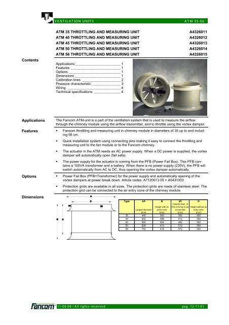
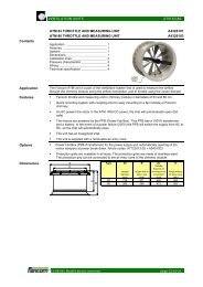
Applications<br />
The Fancom <strong>ATM</strong>-unit is a part of the ventilation system that is used to measure the airflow<br />
through the chimney module using the airflow transmitter, and to throttle using the vortex damper.<br />
Features • Fancom throttling and measuring unit in chimney module in diameters of <strong>35</strong> up to and including<br />
<strong>56</strong> cm.<br />
• Quick installation system using connecting pins making it easy to connect the throttling and<br />
measuring unit to the fan module or to the Fancom chimney.<br />
• The actuator in the <strong>ATM</strong> needs an AC power supply. When a DC power is supplied, the vortex<br />
damper will automatically open (fail safe).<br />
• The power supply for the actuator is coming from the PFB (Power Fail Box). This PFB contains<br />
a 100VA transformer and a battery. When there is no power supply (230V), the PFB will<br />
switch automatically from AC to DC, thus opening the vortex damper automatically.<br />
Options • Power Fail Box (PFB+Transformer) for the power supply and automatically opening of the<br />
vortex dampers at power break down. Article codes: A7<strong>12</strong>0013.05 + A5431003<br />
• Protection grids are available in all sizes. The protection grids are made of stainless steel. The<br />
protection grid can be connected to the air entry cone of the chimney module<br />
Dimensions<br />
Type φA B φC D<br />
Outside diam. of<br />
Height with air the chimney to be Height without air<br />
Largest diameter entry cone connected entry cone<br />
[mm] [mm] [mm] [mm]<br />
<strong>35</strong> 440 393 362 <strong>35</strong>0<br />
40 502 398 4<strong>12</strong> <strong>35</strong>0<br />
45 <strong>56</strong>5 404 462 <strong>35</strong>0<br />
50 628 410 5<strong>12</strong> <strong>35</strong>0<br />
<strong>56</strong> 702 418 572 <strong>35</strong>0<br />
<strong>11</strong>-06-08 / All rights reserved pag. <strong>12</strong>-<strong>11</strong>-01
VENTILATION UNITS <strong>ATM</strong> <strong>35</strong>-<strong>56</strong><br />
Calibration lines<br />
The graph below shows the relationship between the number of revolutions of the airflow transmitter<br />
and the airflow flowing through the <strong>ATM</strong>-unit. If the number of revolutions is known, the air<br />
displacement can be read at the calibration line concerned.<br />
For example: when the airflow transmitter of the <strong>ATM</strong> 45 revolves at a rate of 1500 revolutions per<br />
minute, 4500 m 3 /h is displaced.<br />
The measurements were carried out by an <strong>ATM</strong>-unit equipped with an air entry cone but without a<br />
protection grid. This is connected to the corresponding Fancom fan that is also built into the chimney<br />
module. The measurements were carried out in accordance with the international standards<br />
DIN 1952 (1971), NEN1048 (1962), NBN 688 (1966), NBN 793 (1968).<br />
Measuring range [m3/h]<br />
Type Minimum Maximum<br />
<strong>35</strong> <strong>12</strong>5 <strong>35</strong>00<br />
40 175 5000<br />
45 225 6500<br />
50 275 8000<br />
<strong>56</strong> <strong>35</strong>0 <strong>11</strong>000<br />
<strong>12</strong>,000<br />
Air displacement<br />
in function of revolutions of the airflow transmitter<br />
10,000<br />
<strong>ATM</strong> <strong>56</strong><br />
Air displacement [m 3 /h]<br />
8,000<br />
6,000<br />
4,000<br />
<strong>ATM</strong> 50<br />
<strong>ATM</strong> 45<br />
<strong>ATM</strong> 40<br />
<strong>ATM</strong> <strong>35</strong><br />
2,000<br />
0<br />
0 200 400 600 800 1,000 1,200 1,400 1,600 1,800 2,000<br />
number of revolutions made by the airflow transmitter [rev/min]<br />
<strong>11</strong>-06-08 / All rights reserved pag. <strong>12</strong>-<strong>11</strong>-02
VENTILATION UNITS <strong>ATM</strong> <strong>35</strong>-<strong>56</strong><br />
Pressure<br />
characteristic<br />
With central air exhaust the air displacement per section is based on the application of the pressure<br />
difference. Air will flow because the section is connected to the central duct via the <strong>ATM</strong>-unit,<br />
and because negative pressure is present in the central duct. The graph below shows what the air<br />
displacement will be when a certain pressure difference is applied.<br />
For example: when a pressure difference of 60 Pa is applied over an <strong>ATM</strong> 50, 7000 m 3 /h of air will<br />
flow.<br />
This graph can also be used to read out the pressure necessary to realize a certain air displacement.<br />
Look up the required maximum air displacement and the diameter of the <strong>ATM</strong>-unit, and read<br />
out the pressure necessary.<br />
For example: 6000 m 3 /h, must be displaced. An <strong>ATM</strong> 45 has been chosen. The pressure drop will<br />
be 75 Pa.<br />
The required control range determines the choice of <strong>ATM</strong>-unit diameter. The measuring range is<br />
shown in the table on the previous page. If, in the example above, at least 275 m 3 /h minimum<br />
ventilation is required, an <strong>ATM</strong> 50 could also be chosen. This results in a maximum pressure drop<br />
(at 6000 m 3 /h) of just 45 Pa.<br />
N.B This only refers to the pressure drop over the <strong>ATM</strong>-unit. The total pressure necessary also<br />
depends on the air inlet, duct design etc.<br />
14000<br />
Air displacement<br />
in function of static pressure over the unit<br />
<strong>12</strong>000<br />
<strong>ATM</strong> <strong>56</strong><br />
Air displacement [m 3 /h]<br />
10000<br />
8000<br />
6000<br />
4000<br />
<strong>ATM</strong> 50<br />
<strong>ATM</strong> 45<br />
<strong>ATM</strong> 40<br />
<strong>ATM</strong> <strong>35</strong><br />
2000<br />
0<br />
0 10 20 30 40 50 60 70 80 90 100<br />
Static pressure [Pa]<br />
<strong>11</strong>-06-08 / All rights reserved pag. <strong>12</strong>-<strong>11</strong>-03
VENTILATION UNITS <strong>ATM</strong> <strong>35</strong>-<strong>56</strong><br />
Wiring<br />
Technical<br />
specifications<br />
Connection box 7 x 0,8 mm (0,5 mm 2 )<br />
Operating voltage<br />
Control signal 10-0 V<br />
DSR feedback<br />
AT vortex damper<br />
Supply voltage<br />
18-30Vac<br />
Power consumption<br />
4W<br />
Maximum current<br />
200 mA<br />
Control signal<br />
10-0Vdc<br />
Running time 90° angular rotation<br />
22 sec.<br />
Normal condition at delivery<br />
0Vdc open, 8.5Vdc almost closed<br />
Possibility to adjust the position at maximum control voltage<br />
Trafo<br />
Maximum 16 actuators on 100VA trafo<br />
PFB<br />
Maximum 16 actuators on PFB<br />
Housing<br />
Protection class<br />
IP55<br />
<strong>35</strong> Weight (unpacked) 7.2kg<br />
40 Weight (unpacked) 8.0kg<br />
45 Weight (unpacked) 9.4kg<br />
50 Weight (unpacked) 10.6kg<br />
<strong>56</strong> Weight (unpacked) <strong>11</strong>.6kg<br />
Ambient climate<br />
Operating temperature range<br />
Storage temperature range<br />
Relative humidity<br />
0°C to +40°C (32°F to 104°F)<br />
-10°C to +50°C (50°F to <strong>12</strong>2°F)<br />


![12-21 Dakkokersysteem 63-80 [GB] - Farmi Tilatech Oy](https://img.yumpu.com/37523556/1/184x260/12-21-dakkokersysteem-63-80-gb-farmi-tilatech-oy.jpg?quality=85)