IN0020_01 004799 SPF Grid - Gen Backup Installation Notes
IN0020_01 004799 SPF Grid - Gen Backup Installation Notes
IN0020_01 004799 SPF Grid - Gen Backup Installation Notes

Create successful ePaper yourself
Turn your PDF publications into a flip-book with our unique Google optimized e-Paper software.
SP PRO <strong>Grid</strong> fail – <strong>Gen</strong>erator <strong>Backup</strong> Kit<br />
<strong>Installation</strong> Note<br />
SP PRO <strong>Grid</strong> fail - <strong>Gen</strong>erator <strong>Backup</strong> Kit<br />
<strong>Installation</strong> Note<br />
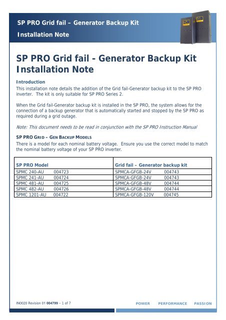
Introduction<br />
This installation note details the addition of the <strong>Grid</strong> fail-<strong>Gen</strong>erator backup kit to the SP PRO<br />
inverter. The kit is only suitable for SP PRO Series 2.<br />
When the <strong>Grid</strong> fail-<strong>Gen</strong>erator backup kit is installed in the SP PRO, the system allows for the<br />
connection of a backup generator that is automatically started and stopped by the SP PRO as<br />
required during a grid outage.<br />
Note: This document needs to be read in conjunction with the SP PRO Instruction Manual<br />
SP PRO GRID – GEN BACKUP MODELS<br />
There is a model for each nominal battery voltage. Ensure you use the correct model to match<br />
the nominal battery voltage of your SP PRO inverter.<br />
SP PRO Model<br />
<strong>Grid</strong> fail – <strong>Gen</strong>erator backup kit<br />
SPMC 240-AU 004723 SPMCA-GFGB-24V 004743<br />
SPMC 241-AU 004724 SPMCA-GFGB-24V 004743<br />
SPMC 481-AU 004725 SPMCA-GFGB-48V 004744<br />
SPMC 482-AU 004726 SPMCA-GFGB-48V 004744<br />
SPMC 12<strong>01</strong>-AU 004722 SPMCA-GFGB-120V 004745<br />
<strong>IN0020</strong> Revision <strong>01</strong> <strong>004799</strong> – 1 of 7 POWER PERFORMANCE PASSION
SP PRO <strong>Grid</strong> fail – <strong>Gen</strong>erator <strong>Backup</strong> Kit<br />
<strong>Installation</strong> Note<br />
Wiring Overview<br />
The following is an overview of the internal and external connections which form part of the<br />
<strong>Grid</strong> – <strong>Gen</strong> <strong>Backup</strong> Expansion housing.<br />
Note: Diagram is applicable for 24V, 48V and 120V models.<br />
SP PRO <strong>Installation</strong><br />
The SP PRO unit is installed as per the installation instructions in the user manual.<br />
All wiring is carried out in the SP PRO with the exception of the grid L input and the generator L<br />
input wiring. These are wired to the <strong>Grid</strong> fail-<strong>Gen</strong>erator backup kit once it is installed.<br />
When connecting the AC wiring to the SP PRO, please leave enough space for the <strong>Grid</strong> fail-<br />
<strong>Gen</strong>erator backup kit to be installed in the wiring cavity of the SP PRO.<br />
Please note the following:<br />
1. <strong>Backup</strong> loads connect into the AC Load L and N terminals in the SP PRO.<br />
2. Only the L wire from the <strong>Grid</strong> fail-<strong>Gen</strong>erator backup connects into the AC Source L<br />
terminal within the SP PRO.<br />
3. The <strong>Grid</strong> L connects to the GRID L terminal on the <strong>Grid</strong> fail-<strong>Gen</strong>erator backup kit. The<br />
<strong>Grid</strong> N connects to the AC source N on the SP PRO.<br />
4. The <strong>Gen</strong>erator L connects to the GEN L terminal on the <strong>Grid</strong> fail-<strong>Gen</strong>erator backup kit.<br />
The <strong>Gen</strong>erator N connects to the AC source N on the SP PRO.<br />
<strong>IN0020</strong> Revision <strong>01</strong> <strong>004799</strong> – 2 of 7 POWER PERFORMANCE PASSION
SP PRO <strong>Grid</strong> fail – <strong>Gen</strong>erator <strong>Backup</strong> Kit<br />
<strong>Installation</strong> Note<br />
Once the SP PRO has been installed and wired, follow the steps below to install the <strong>Grid</strong> fail –<br />
<strong>Gen</strong>erator backup kit.<br />
Installing the <strong>Grid</strong> fail-<strong>Gen</strong>erator backup kit into the SPPRO<br />
Referring to the diagram above, follow the steps below to install the kit.<br />
1. Fit 2 x 5mm mounting screws to the base of the SP PRO inverter at position A. Leave<br />
screws loose.<br />
2. Fit <strong>Grid</strong> fail-<strong>Gen</strong>erator backup kit to screws as shown. Tighten screws.<br />
3. Wire the connections from the <strong>Grid</strong> fail-<strong>Gen</strong>erator backup kit to the SP PRO as shown.<br />
NOTE the polarity of the B+ and B- connections<br />
4. Wire the <strong>Gen</strong>erator L and <strong>Grid</strong> L to the GEN L and GRID L terminals respectively on the<br />
<strong>Grid</strong> fail-<strong>Gen</strong>erator backup kit.<br />
5. Double check all terminals are tight and clamping the wire only and not the insulation.<br />
<strong>IN0020</strong> Revision <strong>01</strong> <strong>004799</strong> – 3 of 7 POWER PERFORMANCE PASSION
SP PRO <strong>Grid</strong> fail – <strong>Gen</strong>erator <strong>Backup</strong> Kit<br />
<strong>Installation</strong> Note<br />
<strong>Gen</strong>erator Control Wiring<br />
The <strong>Gen</strong>erator Run control wiring is wired into the expansion card as shown. This configuration<br />
is for a controller that require two wires to be closed to start and run and then opened to stop<br />
the generator.<br />
Note: Refer to Tech Note TN0025 for other control options.<br />
SP PRO Configuration – Additional Configuration Settings<br />
The following details the additional settings required to activate the <strong>Grid</strong> / <strong>Gen</strong>erator backup<br />
hardware installed. This is in addition to settings for grid operation.<br />
AC SOURCE – AC INPUT<br />
The Alternative Source must set to accommodate the different power limit and<br />
voltage/frequency range that the SP PRO will accept when the backup generator is running.<br />
The Primary Source settings are shown by way of comparison between grid and backup<br />
generator.<br />
Alternate AC Source Power – maximum power SP PRO will draw from backup generator<br />
Min, Max AC Voltage – allowable voltage range from generator<br />
Min, Max AC Frequency – allowable frequency range from generator<br />
<strong>IN0020</strong> Revision <strong>01</strong> <strong>004799</strong> – 4 of 7 POWER PERFORMANCE PASSION
SP PRO <strong>Grid</strong> fail – <strong>Gen</strong>erator <strong>Backup</strong> Kit<br />
<strong>Installation</strong> Note<br />
Note: Default Values shown - Adjust values to suit the backup generator. External CT and<br />
Extern. Contactor/CT settings are not used in this configuration.<br />
AC SOURCE – GENERATOR CONTROLLER SETTINGS<br />
<strong>Gen</strong>erator Controller: Enabled<br />
Note: Remaining settings can be adjusted based on<br />
specific backup generator requirements. See SP PRO<br />
User Manual – <strong>Gen</strong>erator Controller Settings for<br />
further details.<br />
INPUTS / OUTPUTS<br />
The SP PRO must be configured to control the correct inputs and outputs to monitor and switch<br />
between the grid and backup generator.<br />
<strong>IN0020</strong> Revision <strong>01</strong> <strong>004799</strong> – 5 of 7 POWER PERFORMANCE PASSION
SP PRO <strong>Grid</strong> fail – <strong>Gen</strong>erator <strong>Backup</strong> Kit<br />
<strong>Installation</strong> Note<br />
Digital Inputs –<br />
Normal/Alternate AC Input Power Selector: Follow <strong>Backup</strong> Select<br />
Inhibit Export Input: Follow <strong>Backup</strong> Select<br />
Note: Low Batt Shut Down Override Input setting is not used in this<br />
configuration.<br />
<strong>Grid</strong> Fail <strong>Gen</strong>erator <strong>Backup</strong> –<br />
<strong>Grid</strong> Fail <strong>Backup</strong>: Enabled<br />
<strong>Grid</strong> Available Input: Digital Control Input 4<br />
<strong>Backup</strong> Select Output: Relay Output 3<br />
<strong>Gen</strong>erator Outputs –<br />
<strong>Gen</strong>erator Run Output – Relay Output 1<br />
The actual generator output type used will depend on what signal is<br />
required by the backup generator to start and stop. Refer to generator<br />
documentation for details.<br />
Note: Default settings shown. Start Output is not used in this<br />
configuration.<br />
<strong>IN0020</strong> Revision <strong>01</strong> <strong>004799</strong> – 6 of 7 POWER PERFORMANCE PASSION
SP PRO <strong>Grid</strong> fail – <strong>Gen</strong>erator <strong>Backup</strong> Kit<br />
<strong>Installation</strong> Note<br />
SP PRO Configuration – Automatic <strong>Gen</strong>erator Control<br />
The generator will run upon loss of grid supply on the default settings based on low battery<br />
voltage or SoC if enabled. If you wish to enhance this operation, consult SP PRO User manual<br />
– <strong>Gen</strong>erator Automatic Start for full details.<br />
Reference Information<br />
RL1 - VOLTAGE MONITOR<br />
The internal voltage monitor(RL1) is factory set and should not be adjusted. The factory<br />
setting is detailed below:<br />
: + 15 %<br />
: - 8 %<br />
: 3 s<br />
: DIP-switches – under cover –<br />
1 – ON (DEL-REC)<br />
2 – OFF (N.E.)<br />
3 – ON (6 s)<br />
4 – OFF (INHIBIT)<br />
5 – ON (230 VAC)<br />
6 – OFF (230 VAC)<br />
WARNING: Do not open the DIP-switches cover if the Power Supply is ON.<br />
Additional Information<br />
Selectronic web site – http://www.selectronic.com.au or contact the Selectronic Sales Team.<br />
+61 3 9727 6600<br />
www.selectronic.com.au<br />
<strong>IN0020</strong> Revision <strong>01</strong> <strong>004799</strong> – 7 of 7 POWER PERFORMANCE PASSION