Z3 Siren Installation & Operation Manual - Code 3 Public Safety ...
Z3 Siren Installation & Operation Manual - Code 3 Public Safety ...
Z3 Siren Installation & Operation Manual - Code 3 Public Safety ...

Create successful ePaper yourself
Turn your PDF publications into a flip-book with our unique Google optimized e-Paper software.
§¢£¨¡©£¡¢ £¢©¨©¤£¨¤¥ ¡¢£¨¡¤©¡¢¨¤§¢¤¤<br />
¡£¤¨¡¢¨¤<br />
¡£¡¢¨¤!<br />
¡¢£¤¢£¥¦<br />
$¢%¢&'¨¤¢¥££¡¢( §¢¥££¡¢&)¡¢£¢(<br />
¡¢¢¤£¡¢¥+ *¤¨'¡,¤¨-¥£¨£¡¢./ ¡¢£¨¡¤©¡¢¢¤£¡¢¥./<br />
£¡¨"¤££¢¥#<br />
¡¢¢¤£¡¢¥.. 0¨¡¤¥¡¡£¢..1 ¨¤¢2¨¢-¨. *¨¨¡,£%<br />
¨¤¢¤£¡¢¥.!<br />
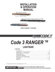
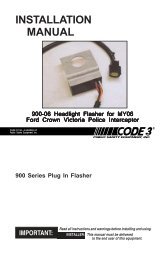
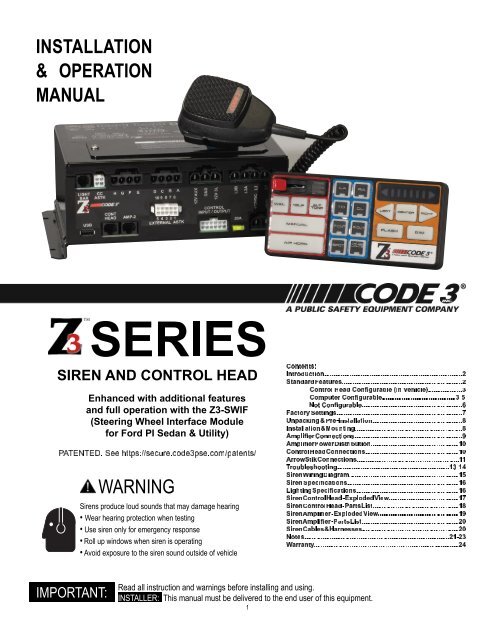
INSTALLATION<br />
& OPERATION<br />
MANUAL<br />
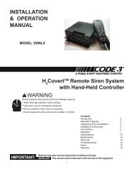
WARNING<br />
6789:89;>?@@ABCDDB>EFG>JAB>M@BD<br />
<strong>Siren</strong>s produce loud sounds that may damage hearing<br />
• Wear hearing protection when testing<br />
• Use siren only for emergency response<br />
• Roll up windows when siren is operating<br />
• Avoid exposure to the siren sound outside of vehicle<br />
IMPORTANT:<br />
Read all instruction and warnings before installing and using.<br />
INSTALLER: This manual must be delivered to the end user of this equipment.<br />
1<br />
¡¢£¨¡¤©45¡©¤©¤,.#<br />
¡¢£¨¡¤©'¨£¥3¥£.( ¨¤¢*¤¨45¡©¤©¤,.+ ¨¤¢*¤¨'¨£¥3¥£/<br />
¤¥&¨¢¤¥¥¤¥/ 3£¢¤£¡¢¥.!<br />
2¨¨¢£"1 ¡£¤¥.
The <strong>Z3</strong> <strong>Siren</strong> is a remote control electronic siren that has been designed to meet the needs of all emergency vehicles. The <strong>Z3</strong> <strong>Siren</strong> incorporates<br />
many of the popular features of the past and uses microprocessor based circuitry and MOSFET technology. All standard features are available along<br />
with many new features that are not available on any other <strong>Code</strong> 3 siren: Fully Confi gurable 3-Level Switch, Selectable Tones, Adjustable<br />
Backlighting and much more. The <strong>Z3</strong> <strong>Siren</strong> can be controlled by the Steering Wheel Interface Ford P.I. Sedan and Utility (The <strong>Z3</strong>-SWIF).<br />
!<br />
WARNING<br />
<strong>Siren</strong>s are an integral part of an effective audio/visual emergency warning system. However, sirens are only short range<br />
secondary warning devices. The use of a siren does not insure that all drivers can or will observe or react to an emergency<br />
warning signal, particularly at long distances or when either vehicle is traveling at a high rate of speed. <strong>Siren</strong>s should only be<br />
used in a combination with effective warning lights and never relied upon as a sole warning signal. Never take the right of way<br />
for granted. It is your responsibility to be sure you can proceed safely before entering an intersection driving against traffi c, or<br />
responding at a high rate of speed.<br />
The effectiveness of this warning device is highly dependent upon correct mounting and wiring. Read and follow the<br />
manufacturer’s instructions before installing this device. The vehicle operator should check the equipment daily to insure that<br />
all features of the device operate correctly.<br />
To be effective, sirens must produce high sound levels that potentially can infl ict hearing damage. Installers should be warned<br />
to wear hearing protection, clear bystanders from the area and not to operate the siren indoors during testing. Vehicle operators<br />
and occupants should assess their exposure to siren noise and determine what steps, such as consultation with professionals<br />
or use of hearing protection should be implemented to protect their hearing.<br />
This equipment is intended for use by authorized personnel only. It is the user’s responsibility to understand and obey all laws<br />
regarding emergency warning devices. The user should check all applicable city, state and federal laws and regulations. <strong>Code</strong><br />
3, Inc., assumes no liability for any loss resulting from the use of this warning device.<br />
Proper installation is vital to the performance of the siren and the safe operation of the emergency vehicle. It is important to<br />
recognize that the operator of the emergency vehicle is under psychological and physiological stress caused by the emergency<br />
situation. The siren system should be installed in such a manner as to: A) Not reduce the acoustical performance of the system,<br />
B) Limit as much as practical the noise level in the passenger compartment of the vehicle, C) Place the controls within convenient<br />
reach of the operator so that he can operate the system without losing eye contact with the roadway.<br />
Emergency warning devices often require high electrical voltages and/or currents. Properly protect and use caution around live<br />
electrical connections. Grounding or shorting of electrical connections can cause high current arcing, which can cause personal<br />
injury and/or severe vehicle damage, including fi re.<br />
PROPER INSTALLATION COMBINED WITH OPERATOR TRAINING IN THE PROPER USE OF EMERGENCY WARNING<br />
DEVICES IS ESSENTIAL TO INSURE THE SAFETY OF EMERGENCY PERSONNEL AND THE PUBLIC.<br />
The <strong>Z3</strong> <strong>Siren</strong> consists of a remotely mounted siren amplifi er with integral lighting control. This is operated by a compact control panel designed to be<br />
conveniently mounted near the operator. This model includes the following standard features:<br />
- Primary Push-Buttons: WAIL, YELP, ALT TONE (Default Tone for ALT TONE is Hi-Lo 1 but can be confi gured to use other tones).<br />
- Secondary Tones: Multiple User Confi gurable Tones.<br />
- MANUAL Push-Button: Default tone is the <strong>Manual</strong> Wail.<br />
- AIR HORN Push-Button: Default tone is Air Horn 1.<br />
- 8 Auxiliary Controls: Default to control Auxiliary A through Auxiliary H outputs. Can be confi gured to control multiple Auxiliary outputs from one<br />
Auxiliary push-button.<br />
- ArrowStik Control: Multiple User Confi gurable Flash Patterns (For use with conventional ArrowStik).<br />
- Integrated Centrally Controlled ArrowStik.<br />
- Integrated <strong>Code</strong> 3 Serial Lightbar Control.<br />
!<br />
WARNING<br />
IMPORTANT WARNINGS TO USERS OF SIRENS: “Wail” and “Yelp” tones are in some cases (such as the state of California)<br />
the only recognized siren tones for calling for the right of way. Ancillary tones such as “Air Horn”, “Hi-Lo”, “Hyper-Yelp”, and<br />
“Hyper-Lo” in some cases do not provide as high a sound pressure level. It is recommended that these tones be used in a<br />
secondary mode to alert motorists to the presence of multiple emergency vehicles or to the momentary shift from the primary<br />
tone as an indication of the imminent presence of any emergency vehicle.<br />
2
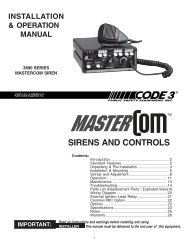
Control Head Configurable (In Vehicle)<br />
Adjustable Backlighting - The Backlighting can be<br />
adjusted as desired. Press and hold either the LEFT or<br />
RIGHT push-buttons for one second. This puts the Control<br />
Head into an adjustment mode for the backlighting.<br />
Repeatedly press or hold the RIGHT push-button to<br />
increase the brightness or the LEFT push-button to<br />
decrease the brightness. The brightness can be decreased<br />
down to include an off condition. Press the DIM push-button<br />
to exit from this adjustment mode. There is also a time-out<br />
that will save the settings before exiting as well.<br />
Microphone Volume Adjustment - Press and hold the<br />
PTT push-button on the microphone. Then press and hold<br />
the Left or Right push-button for one second to enter the<br />
volume adjustment mode. Press the Left or Right arrow<br />
push-buttons to decrease or increase the volume, respectively.<br />
Once it’s adjusted to the desired volume, press the<br />
DIM push-button or release the PTT push-button to save<br />
the setting. There is also a time-out that will save the settings<br />
before exiting as well.<br />
Radio Rebroadcast (RRB) - Radio ReBroadcast over siren<br />
speakers. These inputs are transformer coupled to prevent<br />
Figure 1<br />
loading of the radio. The audio from the radio is rebroadcast<br />
over the siren speakers. The siren tones do not operate when this is activated. All other control functions operate normally. To connect in the signal<br />
to be broadcast, simply connect the two signal lines to the RRB1 and RRB2 inputs of the Amplifi er (polarity is not an issue). The default setting of<br />
the <strong>Z3</strong> <strong>Siren</strong> has this option turned off. See the <strong>Z3</strong> Software User <strong>Manual</strong> for confi guring one of the Auxiliary push-buttons for activating this feature.<br />
Once confi gured to an Auxiliary push-button and that push button is activated, only then can the volume be adjusted by holding down the RIGHT or<br />
LEFT push-button for one second. Pressing the RIGHT or LEFT push-button increases or decreases the volume. Pressing the DIM push-button will<br />
save the settings. There is also a time-out that will save the settings before exiting as well. The RRB feature will automatically shutoff to protect from<br />
overheating of the <strong>Z3</strong> <strong>Siren</strong>.<br />
Computer Configurable<br />
WAIL Push-Button - This push-button produces the Wail tone when pressed. By default, it also turns on the Level 3 lights but this is confi gurable<br />
to Level 2, Level 1 or no lights. The override tone is also confi gurable for this feature. Pressing the push-button a second time turns this feature off.<br />
<strong>Operation</strong> of this feature is affected by <strong>Siren</strong>Lock, 3-Level Switch and Park Kill features. See these sections for details.<br />
YELP Push-Button - This push-button produces the Yelp tone when pressed. By default, it also turns on the Level 3 lights but this is confi gurable<br />
to Level 2, Level 1 or no lights. The override tone is also confi gurable for this feature. Pressing the push-button a second time turns this feature off.<br />
<strong>Operation</strong> of this feature is affected by <strong>Siren</strong>Lock, 3-Level Switch and Park Kill features. See these sections for details.<br />
ALT TONE Push-Button - Both the primary and override tones are confi gurable for this push-button. This push-button produces the Hi-Lo 1 tone<br />
when pressed. It also turns on the Level 3 lights but this is confi gurable to Level 2, Level 1 or no lights. The override tone is the Hyper-Lo 1 tone.<br />
Pressing the push-button a second time turns this feature off. This push-button can be disabled in the confi guration software. <strong>Operation</strong> of this<br />
feature is affected by <strong>Siren</strong>Lock, 3-Level Switch and Park Kill features. See these sections for details.<br />
MANUAL Push-Button - In its default confi guration, this push-button generates the <strong>Manual</strong> Wail tone. When pressed, the <strong>Manual</strong> Wail tone will<br />
ramp up to the maximum tone and hold. It will hold as long as the MANUAL push-button is held. When the MANUAL push-button is released, the<br />
tone will ramp down and return to the previous function. The confi guration software can change this to be in Hit-N-Go mode, Scroll mode, or Wail<br />
Stop mode. This can also be confi gured to react differently based on <strong>Siren</strong> status or Disabled. <strong>Operation</strong> of this feature is affected by <strong>Siren</strong>Lock,<br />
3-Level Switch and Park Kill features. See these sections for details.<br />
AIR HORN Push-Button - In its default confi guration, the AIR HORN push-button produces the Air Horn 1 tone as long as it is pressed. It will<br />
override all other siren tones. The confi guration software can set this tone to Air Horn 1 or Air Horn 2 or to disable the AIR HORN push-button.<br />
The AIR HORN push-button will work with Park Kill and <strong>Siren</strong>Lock. See the <strong>Z3</strong> <strong>Siren</strong> Confi guration Software User <strong>Manual</strong> for confi guration details.<br />
3
Computer Configurable-Cont:<br />
Auxiliary A-H Push-Buttons -As confi gured by the <strong>Z3</strong> <strong>Siren</strong> Confi guration Software, eight on/off Auxiliary push-buttons are readily accessible for<br />
controlling the Auxiliary outputs of the Amplifi er. Each Auxiliary push-button can be custom labeled with the supplied label kit. Each push-button is<br />
backlighted when activated to alert the operator. The default setting is for each Auxiliary push-button to control the corresponding Auxiliary output of<br />
the Amplifi er. Auxiliary A through F supplies power to the load through the connector pins labeled A thru F. Auxiliary G and H supplies power with a<br />
positive or ground voltage to the load through the connector pins labeled G and H. All eight Auxiliary push buttons can be confi gured to be disabled<br />
with the vehicle ignition. Please see the <strong>Z3</strong> <strong>Siren</strong> Confi guration Software User’s <strong>Manual</strong> for details.<br />
3-Level Switch - The Control Head provides a 3-Level Switch for changing the emergency warning mode. The 3-Level Switch is located in the<br />
top left corner of the control head. When the 3-Level Switch is switched to the far left position, the unit is off. When the 3-Level Switch is in the fi rst<br />
position from the left, the level 1 confi guration of the lights is turned on. When the 3-Level Switch is in the second position from the left, the level 1<br />
& 2 confi guration of lights are turned on. When the 3-Level Switch is in the third position from the left, the level 1, 2, & 3 confi guration of the lights<br />
are turned on. Level 1, 2, & 3 activate the LightAlert. These default settings can be altered using the <strong>Z3</strong> <strong>Siren</strong> Confi guration Software. The 3-Level<br />
Switch may be overridden by other push-buttons. If the push-buttons are programmed to a higher level than the position of the 3-Level Switch, the<br />
push-buttons will take precedence. If the push-buttons are programmed to a lower level than the position of the 3-Level Switch, the 3-Level Switch<br />
will take precedence. The lighting can be set to various levels for the WAIL, YELP, ALT TONE, MANUAL, and AUX push-buttons. Visit these sections<br />
in the confi guration software to set these preferences.<br />
3-Color Status LED - Three LEDs are visible on the <strong>Z3</strong> Control Head. When the 3-Level Switch is set to Level 1 the green LED lights. When the<br />
3-Level Switch is set to Level 2 both the green and yellow LEDs light. When the 3-Level Switch is set to Level 3 the green, yellow, and red LEDs<br />
light. These LEDs indicate the level of the siren and controls. These levels are confi gurable in the <strong>Z3</strong> <strong>Siren</strong> Confi guration Software User <strong>Manual</strong>.<br />
Hands-Free - The Hands-Free mode is directly linked to the Auxiliary push-buttons. By default, the Hands-Free mode is disabled. When an Auxiliary<br />
push-button is confi gured for Hands-Free and that Auxiliary push-button has been turned on, the Hands-Free mode is active, but waiting for an initial<br />
press of the horn ring to activate the WAIL push-button. A second press of the horn ring will activate the YELP push-button. Pressing the horn ring a<br />
third time will activate the ALT TONE push-button. A fourth press of the horn ring will return to the WAIL push-button. This type of scrolling will<br />
continue until the user deactivates the Hands-Free Scroll. Pressing the Auxiliary push-button turns off the tone and deactivates the Hands-Free<br />
Scroll. Pressing and holding the horn ring will turn off the tone, but leave Hands-Free in the active mode. The Remote input and <strong>Manual</strong> push-button<br />
can also be confi gured for multiple functions during Hands-Free mode. Please refer to <strong>Z3</strong> <strong>Siren</strong> Confi guration <strong>Manual</strong> for details.<br />
Horn Ring - The <strong>Z3</strong> <strong>Siren</strong> accepts either a positive or a ground signal into the Horn Ring input. The Horn Ring signal is disconnected from the<br />
vehicle and connected to the Horn Ring input. The Horn Relay wire is then run from the Amplifi er to the horn of the vehicle. This allows the Horn Ring<br />
to execute some of the user selectable functions of the <strong>Z3</strong> <strong>Siren</strong>. The Horn Ring can be confi gured to multiple functions in the <strong>Siren</strong> Active and <strong>Siren</strong><br />
Inactive modes of operation. The Horn Ring is set to Scroll in the Hands-Free mode and cannot be changed. Please see the <strong>Z3</strong> <strong>Siren</strong> Confi guration<br />
Software User’s <strong>Manual</strong> for details.<br />
Horn Ring Transfer - The Horn Ring Transfer allows the Horn Ring to be disabled from the vehicle horn and the controls transferred to control other<br />
siren tones. The Horn Ring Transfer can be set to occur at Level 1, Level 2 or Level 3.<br />
Remote - The <strong>Z3</strong> <strong>Siren</strong> accepts either a positive or a ground signal into the Remote Input. The Remote Input is designed to be connected to a user<br />
supplied switch. The <strong>Z3</strong> <strong>Siren</strong> is factory set for a ground signal. The Remote input can be confi gured to multiple functions in the <strong>Siren</strong> Active, <strong>Siren</strong><br />
Inactive and Hands-Free modes of operation. Please refer to the <strong>Z3</strong> <strong>Siren</strong> Confi guration Software User’s <strong>Manual</strong> for details.<br />
Hit-N-Go - Hit-N-Go only works when a siren tone is active. Once a siren tone is active, Hit-N-Go is activated simply by pressing the vehicle horn<br />
ring or activating the Remote input. It will go to the Override tone for 8 seconds and then return to the primary tone. The actual tone for the Hit-N-Go<br />
depends on which push-button is active. If the WAIL push-button is active then the Hit-N-Go (Override) tone is the Yelp tone. If the YELP push-button<br />
is active then the Hit-N-Go tone is the Hyper-Yelp 1 tone and if the ALT TONE push-button is active then the Hit-N-Go tone is the Hyper-Lo 1 tone.<br />
These Override tones are user confi gurable in the Confi guration Software. The <strong>Z3</strong> <strong>Siren</strong> can also be confi gured so the MANUAL push-button is<br />
Hit-N-Go activator.<br />
The InterClear output will turn on for 8 seconds anytime the <strong>Z3</strong> <strong>Siren</strong> operates the Hit-N-Go mode. The InterClear output provides a +12V<br />
signal to control an external device for additional warning.<br />
NOPQR<br />
Scroll - Scroll only works when a siren tone is active. Once a siren tone is active, Scroll is activated simply by pressing the vehicle horn ring or<br />
activating the Remote input. The <strong>Z3</strong> <strong>Siren</strong> will Scroll from Wail to Yelp to Alt and then back to Wail. Holding the vehicle horn ring for greater than a<br />
half second will cause the <strong>Z3</strong> <strong>Siren</strong> to generate the Air Horn. The siren can also be confi gured so the MANUAL push-button activates Scroll.<br />
The InterClear output will turn on for 8 seconds anytime the <strong>Z3</strong> <strong>Siren</strong> operates the Scroll mode. The InterClear output provides a +12V<br />
signal to control an external device for additional warning.<br />
NOPQR<br />
4
Computer Configurable-Cont:<br />
Scroll On/Off - The Scroll On/Off mode works like the Scroll mode except the <strong>Z3</strong> <strong>Siren</strong> will scroll the primary tones through an off state. The <strong>Z3</strong> <strong>Siren</strong><br />
will scroll from Off to Wail to Yelp to Alt Tone and then back to Off. The Remote input can be confi gured to activate Scroll On/Off. Holding the vehicle<br />
horn ring for greater than a half second will cause the <strong>Z3</strong> <strong>Siren</strong> to generate the Air Horn.<br />
The InterClear output will turn on for 8 seconds anytime the <strong>Z3</strong> <strong>Siren</strong> operates the Scroll On/Off mode. The InterClear output provides a<br />
+12V signal to control an external device for additional warning.<br />
STUVW<br />
Load Management - The Load Manager allows setup of three Dropout Voltage Groups by selecting which output to drop out when the vehicle power<br />
levels fall below the specifi ed voltage for that group. The default is for no groups to drop out. See the <strong>Z3</strong> <strong>Siren</strong> Confi guration Software User <strong>Manual</strong><br />
for confi guration details.<br />
LoadMGR TM - This output can control the power supplied to other loads in the vehicle. The power to these loads can be turned off when the driver<br />
turns off the vehicle or the voltage of the battery for the vehicle has dropped below a predetermined voltage level. If the Sleep Mode timer is set to a<br />
value other than instant, the LoadMGR will turn off after the Sleep Mode timer has expired (see the defi nition of Sleep Mode). This output is current<br />
limited to 1 amp continuous. Connecting the LoadMGR output to an external relay will allow larger external loads to be controlled. The InterClear ®<br />
wire is used for the LoadMGR function. InterClear and LoadMGR cannot be confi gured simultaneously.<br />
Overvoltage Protection - The <strong>Z3</strong> <strong>Siren</strong> is designed with an enhanced Overvoltage Protection circuit. This circuit will monitor the input voltage to the<br />
<strong>Z3</strong> <strong>Siren</strong> and will shut off the siren tones if an overvoltage condition is detected. This protects the speaker driver from damage. This feature has been<br />
enhanced to operate with today’s vehicle charging systems. The <strong>Z3</strong> <strong>Siren</strong> will generate siren tones for 15 minutes even in an overvoltage condition.<br />
After 15 minutes the siren tones will be turned off. If the siren tones are still required, the tone can be turned off and on again by pressing the siren<br />
tone push-button. This will provide an additional 15 minutes of operation. This feature can be disabled.<br />
Please see the <strong>Z3</strong> <strong>Siren</strong> Confi guration Software User’s <strong>Manual</strong> for details.<br />
Park Kill - By default, the Park Kill puts the siren tones in standby and drops out the Level 3A output. Park Kill occurs when the vehicle is shifted into<br />
park. The default for the polarity of the Park Kill input is ground (confi gurable to a +12V). Once Park Kill is activated, the siren tones are in standby.<br />
The siren tones will remain in standby until the vehicle is shifted into drive and an action occurs such as pressing one of the Control Head<br />
push-buttons, changing the position of the 3-Level Switch, or keying the microphone. The Level 3A and siren tones are in standby during Park Kill<br />
and the Auxiliary push-buttons are not affected by the Park Kill function by default. See the <strong>Z3</strong> <strong>Siren</strong> Confi guration Software manual for details.<br />
InterClear ® - The InterClear output will turn on for 8 seconds anytime the <strong>Z3</strong> <strong>Siren</strong> operates the Hit-N-Go, Scroll, Scroll On/Off or Hands-Free Scroll.<br />
The InterClear output provides a +12V signal to control an external device for additional warning. It is internally current limited at 1 Amp. The<br />
InterClear feature is disabled if the LoadMGR is confi gured. See the <strong>Z3</strong> <strong>Siren</strong> Confi guration Software manual for details.<br />
EU Lock - This function is to meet the requirements of some European Union countries to verify that the Warning Lights for the emergency vehicle<br />
are operational before allowing the siren to generate tones. This is normally disabled. When confi gured as the EU Lock input all other confi gurations<br />
of the Remote are disabled. In this mode, the Remote is connected to a user supplied light sense module that provides a signal that indicates if the<br />
emergency lights are operational or not. When there is no signal to the Remote input all siren tones will be disabled.<br />
<strong>Siren</strong>Lock - <strong>Siren</strong>Lock is used to set which 3-Level Switch position (Level 1, 2 or 3) will allow the <strong>Z3</strong> <strong>Siren</strong> to generate the Primary tones. When<br />
<strong>Siren</strong>Lock is enabled, the <strong>Z3</strong> <strong>Siren</strong> is ‘Locked’ from generating Primary tones until the confi gured 3-Level Switch position is activated. <strong>Siren</strong>Lock<br />
does not affect the MANUAL and AIR HORN push-buttons. The default for <strong>Siren</strong>Lock is disabled and the <strong>Z3</strong> <strong>Siren</strong> will generate Primary tones when<br />
the push-button (Wail, Yelp or Alt) is activated regardless of the position of the 3-Level Switch.<br />
LightAlert - By default, the LightAlert feature will produce an audible “beep” on a periodic basis if any lighting is activated including Auxiliary and<br />
ArrowStik push-buttons. This is intended to alert the operator that lights are on. The <strong>Z3</strong> <strong>Siren</strong> Confi guration Software allows this feature to be<br />
disabled for individual functions.<br />
Sleep Mode - This is by default set to instantly turn off the <strong>Z3</strong> <strong>Siren</strong> when the vehicle ignition is turned off. This can also be set in the confi guration<br />
software to turn off after 10, 20, or 30 minutes or 1, 2, or 4 hours. The <strong>Z3</strong> <strong>Siren</strong> can be forced to exit Sleep Mode and turn off instantly by pressing<br />
and holding the FLASH push-button for 1 second.<br />
5
Not Configurable<br />
Alarm - Connect the wire labeled ALARM to a circuit that can supply a +12VDC signal when activated. When a +12VDC signal is seen on this input,<br />
a repetitive alarm will sound on the output speakers until the +12VDC signal is removed. For example, this can be used to alarm the police offi cer<br />
when a temperature sensor on a K-9 unit has reached dangerous levels. The ALARM input will operate with the IGNITION input on or off.<br />
Automatic Short Circuit Protection - The <strong>Z3</strong> <strong>Siren</strong> will sense a short circuit on the speaker outputs and automatically go into standby until the fault<br />
is removed. Once the fault is removed, the <strong>Z3</strong> <strong>Siren</strong> will return to normal operation.<br />
Power Up Self Test - When the <strong>Z3</strong> <strong>Siren</strong> system is powered up with the vehicle ignition, it will test the communication between the Amplifi er and the<br />
Control Head. If this test fails, the Control Head will blink all LEDs and beep until communication is established.<br />
Instant On - There is no “ON/OFF” switch. If the <strong>Z3</strong> <strong>Siren</strong> is properly installed and the vehicle’s ignition is switched on, selecting any siren function or<br />
keying the microphone will activate the selected siren function.<br />
Microphone - Push-To-Talk (PTT) is highest priority and overrides all other siren tones. Pressing the push-button on the microphone will<br />
automatically override all siren tones and switch to the public address mode. The microphone is easily plugged into the Control Head with a modular<br />
phone plug. This allows the microphone to be unplugged for easy service or replacement.<br />
Stuck Mic - If the PTT is pressed for 30 seconds , the <strong>Z3</strong> <strong>Siren</strong> will disable the PTT and return to the previous operation. This will avoid the situation<br />
where the PTT is “stuck” in the one position for extended periods. To continue using the PTT, release the PTT and press it again.<br />
Blown Fuse Indicator - The <strong>Z3</strong> <strong>Siren</strong> will give a visual warning if there is no power being supplied to any 3-Level output or to the Auxiliary A through<br />
F outputs. This can be caused by a loss of power to the <strong>Z3</strong> <strong>Siren</strong> power harness or by a blown fuse in the <strong>Z3</strong> <strong>Siren</strong>. If any 3-Level output has no<br />
power, the 3-Level Switch LEDs will blink to indicate that there is a fault. If any of the Auxiliary A through F outputs has no power, all activated<br />
Auxiliary A through F LEDs will blink to indicate that there is a fault. The fuses can be easily accessed through the top of the <strong>Z3</strong> <strong>Siren</strong>.<br />
6
FACTORY SETTINGS<br />
Setting 1 Setting 2 Setting 3 Setting 4 Setting 5 Setting 6<br />
3-Level Switch Function = Progressive<br />
Level 1 Function Enabled Horn Ring Transfer = Not Activated Activate ArrowStik = None Activate Auxiliary Switch = None<br />
Level 2 Function Enabled Horn Ring Transfer = Activated Activate ArrowStik = None Activate Auxiliary Switch = None<br />
Level 3 Function Enabled Horn Ring Transfer = Activated Activate ArrowStik = None Activate Auxiliary Switch = None<br />
ArrowStik Conventional ArrowStik = None<br />
LEFT Function Enabled<br />
CENTER Function Enabled<br />
RIGHT Function Enabled<br />
FLASH Function Enabled<br />
DIM No Confi guration Available<br />
Horn Ring Enable = With Horn Ring Transfer <strong>Siren</strong> Active = Hit-N-Go Hands-Free = Scroll Polarity = Ground <strong>Siren</strong> Inactive = None<br />
Park Kill 3-Level Switch Control = Level 3A Standby <strong>Siren</strong> Control = <strong>Siren</strong> Standby Auxiliary Switch Control = No Impact Polarity = Ground<br />
LightAlert 3-Level Switch = All Auxiliary Switches = All ArrowStik = All<br />
Sleep Mode Sleep Mode = Instant<br />
CA T13 CA T13 = Disabled<br />
Remote Enable = With Horn Ring Transfer <strong>Siren</strong> Active = Hit-N-Go Hands-Free = None Polarity = Ground <strong>Siren</strong> Inactive = None EU Lock = Disabled<br />
Load Management<br />
Group 1 Voltage Fault Threshold = 11.50 Volts Dropout Delay = 1 Minute 3-Level Switch = Off Auxiliary Push-Buttons = Off ArrowStik = Off LoadMGR = Off<br />
Group 2 Voltage Fault Threshold = 11.00 Volts Dropout Delay = 1 Minute 3-Level Switch = Off Auxiliary Push-Buttons = Off ArrowStik = Off LoadMGR = Off<br />
Group 3 Voltage Fault Threshold = 10.50 Volts Dropout Delay = 1 Minute 3-Level Switch = Off Auxiliary Push-Buttons = Off ArrowStik = Off LoadMGR = Off<br />
Overvoltage Protection Enabled<br />
<strong>Siren</strong>Lock Function Disabled<br />
Other Push-Button Settings<br />
WAIL Primary Tone = Wail Override Tone = Yelp Activates = No Aux Level 3 (Red)<br />
YELP Primary Tone = Yelp Override Tone = Hyper-Yelp 1 Activates = No Aux Level 3 (Red)<br />
ALT TONE Primary Tone = Hi-Lo 1 Override Tone = Hyper-Lo 1 Activates = No Aux Level 3 (Red)<br />
MANUAL <strong>Siren</strong> Active = <strong>Manual</strong> Wail Hands-Free = <strong>Manual</strong> Wail <strong>Siren</strong> Inactive = <strong>Manual</strong> Wail, No AUX Activated, Level 3 (Red)<br />
AIR HORN Enable = Always Enabled Primary Tone = Air Horn 1<br />
AUX A Function Enabled Function = Toggle On/Off Activates = Aux A Disabled with ignition = Off<br />
AUX B Function Enabled Function = Toggle On/Off Activates = Aux B Disabled with ignition = Off<br />
AUX C Function Enabled Function = Toggle On/Off Activates = Aux C Disabled with ignition = Off<br />
AUX D Function Enabled Function = Toggle On/Off Activates = Aux D Disabled with ignition = Off<br />
AUX E Function Enabled Function = Toggle On/Off Activates = Aux E Disabled with ignition = Off<br />
AUX F Function Enabled Function = Toggle On/Off Activates = Aux F Disabled with ignition = Off<br />
AUX G Function Enabled Function = 8 Sec Timed Activates = Aux G Polarity = Positive Disabled with ignition = Off<br />
AUX H Function Enabled Function = Toggle On/Off Activates = Aux H Polarity = Positive Disabled with ignition = Off<br />
7
After unpacking your <strong>Z3</strong> <strong>Siren</strong>, carefully inspect the<br />
unit and associated parts for any damage that may<br />
have been caused in transit. Report any damage to<br />
the carrier immediately.<br />
Verify all components have been delivered. The box<br />
should contain the <strong>Z3</strong> <strong>Siren</strong> Control Head, <strong>Z3</strong><br />
Amplifi er, cable/harness bag, microphone, hardware<br />
bag, legend set and user manuals bag.<br />
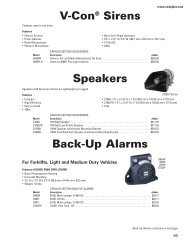
The <strong>Z3</strong> <strong>Siren</strong> Control Head is designed mount<br />
directly into the console of most leading<br />
manufacturers (see Figure 3).<br />
Figure 2<br />
It may also be mounted above the dash, below the dash or on the<br />
transmission tunnel using the mounting hardware supplied (see Figure 2).<br />
Also reference page 17 and 18 for description of components and <strong>Code</strong> 3<br />
part numbers. Ease of operation and convenience to the operator should be<br />
the prime consideration when mounting the siren and controls. When<br />
choosing a mounting location the user must consider the deployment area for<br />
the air bag of the vehicle and other factors which might impact the safety of<br />
the vehicle occupants.<br />
NOTE: Setups and adjustments will be made in steps that may require<br />
access to the rear area of the unit. Plan the installation and wiring<br />
accordingly.<br />
Figure 3<br />
!<br />
WARNING<br />
All devices should be mounted in accordance with the manufacturer’s instructions and securely fastened to vehicle elements<br />
of suffi cient strength to withstand the forces applied to the device. Ease of operation and convenience to the operator should<br />
be the prime consideration when mounting the siren and controls. Adjust the mounting angle to allow maximum operator visibility.<br />
Do not mount the Control Head Module in a location that will obstruct the drivers view. Mount the microphone clip in a<br />
convenient location to allow the operator easy access. Devices should be mounted only in locations that conform to their SAE<br />
identifi cation code as described in SAE Standard J1849. For example, electronics designed for interior mounting should not be<br />
placed underhood, etc. Controls should be placed within convenient reach* of the driver or if intended for two person operation<br />
the driver and/or passenger. In some vehicles, multiple control switches and/or using methods such as “horn ring transfer” which<br />
utilizes the vehicle horn switch to toggle between siren tones may be necessary for convenient operation from two positions.<br />
*Convenient reach is defi ned as the ability of the operator of the siren system to manipulate the controls from their normal driving/riding<br />
position without excessive movement away from the seat back or loss of eye contact with the roadway.<br />
8
All Amplifi er connections are made on one side of the Amplifi er (see Figure 4). See wiring diagram on page 15. All Amplifi er connections are quick<br />
disconnect requiring no tools.<br />
Figure 4<br />
!<br />
WARNING<br />
Larger wires and tight connections will provide longer service life for components. For high current wires it is highly recommended<br />
that terminal blocks or soldered connections be used with shrink tubing to protect the connections. Do not use<br />
insulation displacement connectors (e.g. 3M® Scotchlock type connectors). Route wiring using grommets and sealant when<br />
passing through compartment walls. Minimize the number of splices to reduce voltage drop. High ambient temperatures (e.g.<br />
under-hood) will signifi cantly reduce the current carrying capacity of wires, fuses, and circuit breakers. Use “SXL” type wire<br />
in engine compartment. All wiring should conform to the minimum wire size and other recommendations of the manufacturer<br />
and be protected from moving parts and hot surfaces. Looms, grommets, cable ties, and similar installation hardware should<br />
be used to anchor and protect all wiring.<br />
Particular attention should be paid to the location and method of making electrical connections and splices to protect these<br />
points from corrosion and loss of conductivity. Ground terminations should only be made to substantial chassis components,<br />
preferably directly to the vehicle battery.<br />
The user should install a fuse sized to approximately 125% of the maximum Amp capacity in the supply line and each switched<br />
circuit to protect against short circuits. For example, a 30 Amp fuse should carry a maximum of 24 Amps. DO NOT USE 1/4”<br />
DIAMETER GLASS FUSES AS THEY ARE NOT SUITABLE FOR CONTINUOUS DUTY IN SIZES ABOVE 15 AMPS. Circuit<br />
breakers are very sensitive to high temperatures and will “false trip” when mounted in hot environments or operated close to<br />
their capacity. Fuses or circuit breakers should be located as close to the power takeoff points as possible and properly sized<br />
to protect the wiring and devices.<br />
9
WARNING<br />
!<br />
Connection of a 58 watt speaker to the siren amplifi er will cause the speaker to burn out, and will void the speaker<br />
warranty!<br />
The Level 1, 2, 3A and 3B outputs can supply a maximum of 15 Amps each or a combined total of 50 Amps. Each Level has a 20 Amp fuse installed<br />
inside the Amplifi er. Fuses may be accessed through the panel on top of the Amplifi er.<br />
The Auxiliary outputs A, B, C and D can supply a maximum of 5 amps each. Auxiliary outputs E, F, G and H can supply a maximum of 10 amps each.<br />
The combined total for all Auxiliary outputs is 50 Amps. Auxiliary outputs A, B, C and D have 7.5 amp fuses and Auxiliary outputs E, F, G and H have<br />
15 amp fuses. Fuses may be accessed through the panel on top of the Amplifi er.<br />
WARNING<br />
!<br />
Any electronic device may create or be affected by electromagnetic interference. After installation of any electronic<br />
device, operate all equipment simultaneously to insure that operation is free of interference.<br />
The connection from the Control Head to the remote Amplifi er is made using a standard CAT-5 cable (P/N T56649) connected to the port labeled<br />
SIREN AMP on the back of the Control Head and the CONT HEAD port on the Amplifi er. This cable is found in the Harness & Cable Bag P/N T56641<br />
(see Figure 5).<br />
In addition, the microphone P/N T11856 connects to the Control Head port labeled PA MIC. The microphone also uses a Microphone Hanger Bracket<br />
(P/N T00631) that mounts to the dash of the vehicle.<br />
Figure 5<br />
WARNING<br />
!<br />
Utilizing non-factory specifi ed screws and/or mounting brackets and/or the improper number of screws may result in<br />
failure of the mounting system and severe damage to the vehicle as well as loss of warranty coverage on the equipment.<br />
10
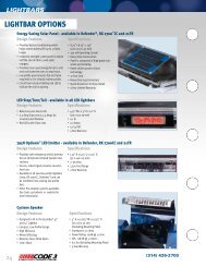
CC ArrowStik Connection<br />
The <strong>Z3</strong> <strong>Siren</strong> can connect directly to any <strong>Code</strong> 3 Centrally Controlled (CC) ArrowStik and some non-<strong>Code</strong>3 CC ArrowStiks using <strong>Code</strong> 3 harness<br />
P/N T56629 (see Figure 8). This harness is found in the Harness & Cable Bag P/N T56641. Refer to the wiring diagram on page 15.<br />
Conventional ArrowStik Connection<br />
The <strong>Z3</strong> <strong>Siren</strong> can also connect directly to a conventional ArrowStik or both at the same time using <strong>Code</strong> 3 harness P/N T56631 (see Figures 6 & 7).<br />
Refer to the wiring diagram on page 15. If a conventional ArrowStik is desired see the <strong>Z3</strong> <strong>Siren</strong> Confi guration Software <strong>Manual</strong> for details regarding<br />
fl ash pattern selection.<br />
The 9 wire harness can be connected to drive a 5, 6, or 8 head ArrowStik. The <strong>Z3</strong> <strong>Siren</strong> is compatible with some non-<strong>Code</strong> 3 ArrowStik products.<br />
The <strong>Z3</strong> <strong>Siren</strong> conventional ArrowStik outputs provide a current sink (ground) signal when active. Each output is rated for a maximum of 5 amps. See<br />
the wiring diagram on page 15 and the install manual for the ArrowStik product for wiring details.<br />
8 HEAD HARNESS CONNECTIONS<br />
When viewing the vehicle from the rear, the ArrowStik harness is connected in the following order from Driver side to Passenger side: Blue, Yellow,<br />
Gray, Green, Violet, Tan, Orange, Brown. The Right Arrow travels from Blue to Brown. The Left Arrow travels from Brown to Blue.<br />
6 HEAD HARNESS CONNECTIONS<br />
When viewing the vehicle from the rear, the ArrowStik harness is connected in the following order from Driver side to Passenger side: Yellow, Gray,<br />
Green, Violet, Tan, Orange. The Right Arrow travels from Yellow to Orange. The Left Arrow travels from Orange to Yellow.<br />
If the <strong>Z3</strong> <strong>Siren</strong> ArrowStik function is confi gured for ArrowStik End Flash, the Blue and Brown wires will attach to the two end light heads.<br />
5 HEAD HARNESS CONNECTIONS<br />
When viewing the vehicle from the rear, the ArrowStik harness is connected in the following order from Driver side to Passenger side: Yellow, Gray,<br />
Violet, Tan, Orange. The Right Arrow travels from Yellow to Orange. The Left Arrow travels from Orange to Yellow.<br />
If the <strong>Z3</strong> <strong>Siren</strong> ArrowStik function is confi gured for ArrowStik End Flash, the Blue and Brown wires will attach to the two end light heads.<br />
DIM Control<br />
The <strong>Z3</strong> <strong>Siren</strong> DIM function supplies +12VDC output when active. This output is compatible with the dimming input of older <strong>Code</strong> 3 ArrowStik<br />
products. It is not used with newer <strong>Code</strong> 3 ArrowStik products. This output can supply an absolute maximum of 1.5 amps.<br />
Programming<br />
The <strong>Z3</strong> <strong>Siren</strong> will come from the factory set to control a CC ArrowStik. For details about ArrowStik pattern selection for <strong>Code</strong> 3 CC ArrowStiks, refer<br />
to the ArrowStik user manual. For an conventional ArrowStik, refer to the <strong>Z3</strong> <strong>Siren</strong> Confi guration Software <strong>Manual</strong>.<br />
The <strong>Z3</strong>-SWIF Connection<br />
The <strong>Z3</strong> <strong>Siren</strong> can be connected to the <strong>Z3</strong>-SWIF using a standard CAT-5 cable (P/N T56649) plugged into the AMP-2 Port on the Amplifi er. See the<br />
<strong>Z3</strong>-SWIF <strong>Installation</strong> <strong>Manual</strong> for instructions on confi guring the <strong>Z3</strong>-SWIF.<br />
11
NON-CC WIRING CONNECTIONS<br />
<br />
<br />
<br />
<br />
<br />
Figure 6<br />
<br />
<br />
<br />
<br />
Figure 7<br />
CC WIRING CONNECTION<br />
<br />
<br />
<br />
Figure 8<br />
<br />
12
Troubleshooting<br />
(Refer to wiring diagram on page 15.)<br />
PROBLEM PROBABLE CAUSE REMEDY<br />
NO SIREN OUTPUT<br />
EXTERNAL 20A FUSE BLOWS<br />
NO OUTPUT FROM SPEAKER, TONES<br />
HEARD INSIDE AMPLIFIER MODULE<br />
SIREN TONES VOLUME TOO LOW/GAR-<br />
BLED<br />
HIGH RATE OF SPEAKER FAILURE<br />
SIREN CONTINUES TO OPERATE FOR 7<br />
SECONDS AFTER MANUAL BUTTON/HORN<br />
RING IS RELEASED<br />
INTERCLEAR WILL NOT POWER AUXILIARY<br />
DEVICES<br />
A. PARK KILL ACTIVATED<br />
B. SIRENLOCK ENGAGED<br />
C. SHORTED SPEAKER OR SPEAKER<br />
WIRES. SIREN IN OVER CURRENT PRO-<br />
TECTION MODE.<br />
D. OVERVOLTAGE > 15V<br />
A. AMPLIFIER POWER WIRES REVERSED<br />
POLARITY<br />
A. SPEAKER NOT CONNECTED/ OPEN<br />
CIRCUIT IN SPEAKER WIRING<br />
B. DEFECTIVE SPEAKERS<br />
A. LOW VOLTAGE TO SIREN AMPLIFIER<br />
B. HIGH RESISTANCE IN WIRING/DEFEC-<br />
TIVE SPEAKER<br />
C. SPEAKERS PHASED IMPROPERLY<br />
A. HIGH VOLTAGE TO SIREN<br />
B. 58 WATT SPEAKER CONNECTED TO 100<br />
WATT TAP. 58 WATT NOT ALLOWED.<br />
A. “HIT-N-GO’ FEATURE ENGAGED. NOR-<br />
MAL OPERATION<br />
A. THERE IS A SHORT IN THE WIRING, OR<br />
THE LOAD IS GREATER THAN 1 AMP.<br />
P. A. VOLUME LOW OR NO P. A. AT ALL. A. INCREASE P.A. VOLUME.<br />
B. MICROPHONE NOT COMPLETELY<br />
PLUGGED IN.<br />
C. DEFECTIVE MICROPHONE<br />
D. COMMON MICROPHONE CIRCUIT NOT<br />
PROPERLY WIRED.<br />
E. INCORRECT MICROPHONE.<br />
RRB VOLUME LOW, OR NO RRB AT ALL.<br />
SIREN SOUNDS BY ITSELF<br />
SIREN RUNS PROPERLY BUT SHUTS<br />
DOWN WHILE RUNNING, THEN STARTS<br />
RUNNING AGAIN AFTER A FEW MINUTES.<br />
WHEN POWERED THERE IS A 5 SECOND<br />
PAUSE AND THEN A FLASH AND BEEP<br />
EVERY 2 SECONDS CONTINUOUSLY WITH-<br />
OUT STOPPING.<br />
A. INCREASE RADIO REBROADCAST<br />
VOLUME.<br />
B. RRB WIRES NOT CONNECTED TO TWO-<br />
WAY RADIO EXTERNAL SPEAKER.<br />
A. REMOTE SWITCH (HORN RING) WIRING<br />
FROM TERMINAL REMOTE SHORTING TO<br />
POSITIVE OR TO GROUND (EARTH).<br />
A. VEHICLE CIRCUIT BREAKERS NOT RAT-<br />
ED PROPERLY, AND ARE OVERHEATING,<br />
OR ARE NOT FUNCTIONING PROPERLY.<br />
A. CONTROL HEAD HAS FAILED TO COM-<br />
MUNICATE WITH THE AMPLIFIER.<br />
B. CONFIGURATION LOAD FAILURE.<br />
A. SHIFT VEHICLE OUT OF PARK.<br />
B. SELECT PROPER SIRENLOCK LEVEL.<br />
C. CHECK CONNECTIONS<br />
D. CHECK VEHICLE BATTERY<br />
A. CHECK POLARITY<br />
B. REPLACE SPEAKER(S)<br />
A. CHECK SPEAKER WIRING<br />
B. REPLACE SPEAKER(S)<br />
A. CHECK WIRING FOR BAD CONNEC-<br />
TIONS/CHECK VEHICLE CHARGING<br />
SYSTEM.<br />
B. CHECK SPEAKER(S) WIRING/REPLACE<br />
SPEAKER(S).<br />
C. REFER TO PAGE 3 FOR PROPER PHAS-<br />
ING (200W OPTION)<br />
A. CHECK VEHICLE CHARGING SYSTEM.<br />
B. USE CORRECT SPEAKER.<br />
A. CHECK FOR SHORTS. INSTALL INTER-<br />
CLEAR BOOSTER KIT (PART #INTBS)<br />
A. REFER TO SETUP AND ADJUSTMENT<br />
SECTION<br />
B. PLUG MICROPHONE IN SECURELY<br />
C. REPLACE MICROPHONE<br />
D. CHECK WIRING<br />
E. CALL CODE 3 FOR LIST OF ADAPTABLE<br />
MICROPHONES.<br />
A. REFER TO SETUP AND ADJUSTMENT<br />
SECTION.<br />
B. CHECK RRB CONNECTIONS.<br />
A. CHECK WIRING FOR ANY SHORTING.<br />
A. REFER TO SPECIFICATIONS SECTION,<br />
PAGE 17. USE A BREAKER RATED AT 1.25<br />
TIMES THE AMPERAGE OF THE EXPECTED<br />
LOAD CURRENT.<br />
A. CHECK CONNECTION OF CAT-5 CABLE<br />
FROM CONTROL HEAD TO AMPLIFIER.<br />
B. RESET POWER.<br />
C. RELOAD AMPLIFIER CONFIGURATION.<br />
D. CONTACT CUSTOMER SERVICE.<br />
13
(Refer to wiring diagram on page 15.)<br />
PROBLEM PROBABLE CAUSE REMEDY<br />
THE GREEN, AMBER, AND/OR RED LEDS<br />
FLASH RAPIDLY AND CONTINUOUSLY.<br />
ANY OF THE ACTIVE AUX A-F PUSH-<br />
BUTTONS FLASH RAPIDLY AND CONTINU-<br />
OUSLY.<br />
IF IN LEVEL 3 AND THE VEHICLE IS IN<br />
PARK, THE RED LEVEL INDICATOR ON THE<br />
CONTROL HEAD IS BLINKING AT A SLOW<br />
RATE.<br />
PA ONLY FUNCTIONS FOR 30 SECONDS<br />
BEFORE TURNING OFF.<br />
RRB SHUTS OFF AFTER EXTENDED USE.<br />
A. ONE OR MORE OF THE 3-LEVEL FUSES<br />
HAVE BLOWN IN THE AMPLIFIER.<br />
B. 12V IS NOT BEING SUPPLIED TO THE<br />
12V 3L INPUT.<br />
C. LEVEL OUTPUT SHORTED<br />
A. ONE OR MORE OF THE AUX A-F FUSES<br />
HAVE BLOWN IN THE AMPLIFIER.<br />
B. 12V IS NOT BEING SUPPLIED TO THE<br />
AUX A-F OUTPUTS.<br />
A. THIS IS NORMAL. THIS IS COMMUNICAT-<br />
ING THAT THE LEVEL 3A OR THE LEVEL 3B<br />
LIGHTS ARE IN STANDBY (TURNED OFF).<br />
B. LOAD MANAGER HAS SENSED LOW<br />
INPUT AND TURNED OFF 3A OR 3B.<br />
A. THIS IS NORMAL. THE PA IS TURNED<br />
OFF AFTER 30 SECONDS TO AVOID THE<br />
STUCK MIC POSSIBILITY.<br />
A. THIS IS NORMAL. THE RRB SHUTS OFF<br />
AFTER AN EXTENDED PERIOD WHEN THE<br />
EQUIPMENT STARTS TO OVERHEAT. THIS<br />
IS TO AVOID DAMAGE TO THE COMPO-<br />
NENTS IN THE AMPLIFIER.<br />
A. REPLACE THE FUSE(S) IN THE AMPLI-<br />
FIER.<br />
B. CHECK INPUT POWER CONNECTION.<br />
C. CHECK CONNECTION TO LOAD<br />
A. REPLACE THE FUSE(S) IN THE AMPLI-<br />
FIER.<br />
B. CHECK HARNESS CONNECTION BE-<br />
TWEEN THE AMPLIFIER AND THE AUXIL-<br />
IARY DEVICES.<br />
A. PUT THE VEHICLE BACK INTO DRIVE.<br />
B. CHECK VEHICLE BATTERY VOLTAGE.<br />
A. SIMPLY RELEASE THE PTT BUTTON AND<br />
PRESS AGAIN FOR ANOTHER 30 SECONDS<br />
OF BROADCAST ABILITY.<br />
A. ALLOW THE AMPLIFIER A FEW MINUTES<br />
TO COOL DOWN.<br />
14
CC ARROWSTIK<br />
T56629<br />
16GA<br />
LEFT ARROW (RED)<br />
RIGHT ARROW (ORANGE)<br />
FLASH (WHITE)<br />
DIM<br />
(BLUE)<br />
CODE 3 SERIAL LIGHTBAR COMM<br />
Cable From Serial Lightbar<br />
<strong>Z3</strong><br />
AMPLIFIER<br />
USB Cable (A to A Male)<br />
T56639<br />
COMPUTER CONFIGURATION<br />
CAT5 Cable T56649 Long<br />
CAT5 Cable T56649 Long<br />
CONVENTIONAL ARROWSTIK<br />
OUTPUTS 1 THRU 8 AND DIM<br />
CONTROL HEAD COMM<br />
AUXILIARY EQUIPMENT<br />
OUTPUT 6 (GRAY)<br />
16GA<br />
OUTPUT 7 (YELLOW)<br />
OUTPUT 8 (BLUE)<br />
DIM (WHITE)<br />
OUTPUT 5 (GREEN)<br />
OUTPUT 4 (VIOLET)<br />
OUTPUT 3 (TAN)<br />
OUTPUT 2 (ORANGE)<br />
OUTPUT 1 (BROWN)<br />
T56631<br />
16GA<br />
15A FUSED<br />
15A FUSED<br />
15A FUSED<br />
15A FUSED<br />
AUX H<br />
AUX G<br />
AUX F<br />
AUX E<br />
TO AUX CONNECTIONS<br />
T56638<br />
8GA<br />
10GA<br />
7.5A FUSED<br />
7.5A FUSED<br />
7.5A FUSED<br />
7.5A FUSED<br />
30A FUSED<br />
NOT FUSED<br />
30A FUSED<br />
20A FUSED<br />
20A FUSED<br />
20A FUSED<br />
20A FUSED<br />
AUX D<br />
AUX C<br />
AUX B<br />
AUX A<br />
+12VDC (AUX)<br />
GND<br />
+12VDC (3-LEVEL)<br />
LEVEL 3B<br />
LEVEL 3A<br />
LEVEL 2<br />
LEVEL 1<br />
TO AUX CONNECTIONS<br />
T56628<br />
LIGHT BOARD POWER<br />
T56627<br />
TO LIGHTBAR<br />
T56630<br />
FUSE*<br />
FUSE*<br />
LIGHT BOARD POWER<br />
T56627<br />
20A FUSE<br />
16GA 12GA<br />
GND<br />
+12VDC<br />
REMOTE<br />
PARK KILL<br />
ALARM<br />
FUSE*<br />
+ -<br />
+12V<br />
BATTERY<br />
AMPLIFIER POWER<br />
T56637<br />
AMPLIFIER POWER<br />
T56637<br />
T56636<br />
RRB 2<br />
RRB 1<br />
IGNITION<br />
HORN RING<br />
HORN RELAY<br />
I. CLEAR<br />
SPEAKER 1<br />
SPEAKER 2<br />
INPUT/OUTPUT<br />
Speaker 1 Speaker 2<br />
ADDITIONAL 100W<br />
100W 100W SPEAKER FOR 200W<br />
TOTAL SYSTEM<br />
GND<br />
BREAK CONNECTION<br />
HORN<br />
* USER SUPPLIED (SEE WARNING IN AMPLIFIER CONNECTIONS SECTION OF THE HARDWARE INSTALL MANUAL)<br />
15
<strong>Siren</strong> Section:<br />
Input Voltage<br />
10 to 16 VDC and ground - 12V units<br />
(Note: <strong>Operation</strong> of 12V units above 15 VDC for an extended period of time may result in speaker damage.)<br />
Operating Current 100W: 8 Amps @ 13.6V with 11-ohm load (100 Watt Speaker) - 12V units<br />
200W: 14 Amps @ 13.6V with 5.5-ohm load (2-100 Watt Speakers) - 12V units<br />
(NOTE: There is no 58 Watt speaker connection available.)<br />
Standby Current<br />
Cycle Rate<br />
Voltage Output<br />
Ignition On < 10mA<br />
Ignition Off < 1mA<br />
Wail - 11 cycles/minute<br />
Yelp - 200 cycles/minute<br />
~ 66 Vpp<br />
Audio Section:<br />
Audio Response<br />
3 dB down points - 500 to 3000 Hz<br />
1000 Hz, 0 dB reference<br />
Warning Light Control:<br />
Level 1 & 2:<br />
Level 3A & 3B:<br />
AUX A thru D:<br />
AUX E thru H:<br />
ArrowStik:<br />
3-Level Switch, 4 Outputs, 50 Amps maximum combined total<br />
15 Amp Maximum Each Level<br />
25 Amp Maximum Total<br />
Green (1) & Yellow (2) LED Indication<br />
15 Amp Maximum Each Level<br />
25 Amp Maximum Total<br />
Red (3) LED Indication<br />
5 Amp Maximum Each Aux<br />
20 Amp Maximum Total<br />
10 Amp Maximum Each Aux<br />
30 Amp Maximum Total<br />
8 Output (not internally fused), Ground Switching, 5A Per Output<br />
DIM Output, +12VDC, 1.5A Internally Protected<br />
System - Weight: Amplifi er 4.2 lbs (1.9 Kg)<br />
Size:<br />
Control Head &<br />
Microphone<br />
Boxed Unit<br />
Amplifi er<br />
Control Head<br />
1.1 lbs (0.5 Kg)<br />
9.5 lbs (4.3 Kg)<br />
9.750”L x 6.832”W x 3.936”H<br />
6.80”L x 3.30”H x 1.07”D (Switch will increase depth dimension to 1.95”D.)<br />
Temperature:<br />
-22F thru +149F (-30C thru +65C) SAE Equipment Type EVS1<br />
16
17
Ref No. Description Purchasable Part No. Internal Part No. (Not For Sale) Qty.<br />
1 8-32 X 1/4” Hex Head MS T10385 2<br />
2 Control Head Mounting Bracket T10924 2<br />
3 1/4”-20 X 3/8” Hex Head MS T10912 2<br />
4 Rev Lock 1/2” Nylon PCB Stdf T56645 7<br />
5 Sheet Metal Base Plate T15287 1<br />
6 .187 OD 4-40 Standoff T10890 2<br />
7 4 Position Switch Assembly T56634 1<br />
8 4-40 X 3/8” Phil Pan HD T06937 2<br />
9 Control HD PCB T11858 1<br />
10 Molded Keypad T15285 1<br />
11 Molded Control Housing T15281 1<br />
12 Moulded Switch Knob T15286 1<br />
13 Part of Amp Box Wiring Label T11863 1<br />
To order a complete <strong>Z3</strong> <strong>Siren</strong> Control Head, order part number S39284M.<br />
To order a complete <strong>Z3</strong> <strong>Siren</strong> Cable & Harness bag, order part number T56641.<br />
To order a complete <strong>Z3</strong> <strong>Siren</strong> <strong>Manual</strong>s & Legends bag, order part number S38284M.<br />
18
19
Ref No. Description Purchasable Part No. Internal Part No. (Not For Sale) Qty.<br />
1 Amplifi er E Tray T15305 All Amplifi er Components 1<br />
2 Amplifi er PCB T11851 Are Purchasable 1<br />
3 #6-32 X .375” Phil Pan HD MS T04250 1<br />
4 #6-32 X 1.875” Hex MF Stdoff T15326 2<br />
5 Outputs & Dim Int Harness T56632 3<br />
6 Light Board PCB T11854 1<br />
7 I2C Comm Cable T56623 1<br />
8 #6-32 X .250 Phil Pan HD MS T07077 3<br />
9 Amplifi er Cover T15307 1<br />
10 Amplifi er Fuse Cover T15310 1<br />
11 #8-32 X .250 Phil Pan HD TRS T09751 2<br />
12 Warning Label T09937 1<br />
13 Wiring Label Fuse Map T11861 1<br />
14 Wiring Label Amp Box Top T11863 1<br />
15 #6-32 X 2.250 Phil Pan HD MS T15328 3<br />
16 Washer, Int Tooth #6 T00150 1<br />
17 #6-32 X 1.500 Phil Pan HD MS T01332 1<br />
18 Wiring Label, Terminal Side T11863 1<br />
To order a complete <strong>Z3</strong> <strong>Siren</strong> Amplifi er, order part number S39285M.<br />
To order a complete <strong>Z3</strong> <strong>Siren</strong> Cable & Harness bag, order part number T56641.<br />
To order a complete <strong>Z3</strong> <strong>Siren</strong> <strong>Manual</strong>s & Legends bag, order part number S38284M.<br />
Ref No. Description Purchasable Part No. Internal Part No. (Not For Sale) Qty.<br />
1 Light Board Power Harness T56627 1<br />
2 Aux A-D Harness T56628 1<br />
3 L/R Arrow, Dim, Flash Harness T56629 1<br />
4 Level 1, 2, 3A, 3B Harness T56630 1<br />
5 Outputs & Dim Ext. Harness T56631 1<br />
6 CAT5 Cable Min 20 FT T56649 1<br />
7 Input/Output Harness T56636 1<br />
8 Amplifi er Power Harness T56637 1<br />
9 Aux E-H Harness T56638 1<br />
10 USB A Male to A Male Cable T56639 1<br />
11 Mic w/Modular Plug T11856 1<br />
To order a complete <strong>Z3</strong> <strong>Siren</strong> Amplifi er, order part number S39285M.<br />
To order a complete <strong>Z3</strong> <strong>Siren</strong> Cable & Harness bag, order part number T56641.<br />
To order a complete <strong>Z3</strong> <strong>Siren</strong> <strong>Manual</strong>s & Legends bag, order part number S38284M.<br />
20
NOTES<br />
21
NOTES<br />
22
NOTES<br />
23
WARRANTY<br />
<strong>Code</strong> 3®, Inc.’s emergency devices are tested and found to be operational at the time of manufacture. Provided they are installed and<br />
operated in accordance with manufacturer’s recommendations, <strong>Code</strong> 3®, Inc. guarantees all parts and components except the lamps to a period<br />
of 1 year, LED Lighthead modules to a period of 5 years (unless otherwise expressed) from the date of purchase or delivery, whichever is later.<br />
Units demonstrated to be defective within the warranty period will be repaired or replaced at the factory service center at no cost.<br />
Use of lamp or other electrical load of a wattage higher than installed or recommended by the factory, or use of inappropriate or<br />
inadequate wiring or circuit protection causes this warranty to become void. Failure or destruction of the product resulting from abuse or unusual<br />
use and/or accidents is not covered by this warranty. <strong>Code</strong> 3®, Inc. shall in no way be liable for other damages including consequential, indirect<br />
or special damages whether loss is due to negligence or breach of warranty.<br />
CODE 3®, INC. MAKES NO OTHER EXPRESS OR IMPLIED WARRANTY INCLUDING, WITHOUT LIMITATION, WARRANTIES OF<br />
FITNESS OR MERCHANTABILITY, WITH RESPECT TO THIS PRODUCT.<br />
PRODUCT RETURNS<br />
If a product must be returned for repair or replacement*, please contact our factory to obtain a Return Goods Authorization<br />
Number (RGA number) before you ship the product to <strong>Code</strong> 3®, Inc. Write the RGA number clearly on the package near<br />
the mailing label. Be sure you use suffi cient packing materials to avoid damage to the product being returned while in<br />
transit.<br />
*<strong>Code</strong> 3®, Inc. reserves the right to repair or replace at its discretion. <strong>Code</strong> 3®, Inc. assumes no responsibility or liability for expenses incurred for the removal and /or reinstallation of products requiring service and/or repair; nor for the<br />
packaging, handling, and shipping: nor for the handling of products returned to sender after the service has been rendered.<br />
Problems or Questions? Call The Technical Assistance HOTLINE - (314) 996-2800<br />
<strong>Code</strong> 3, Inc.<br />
10986 N. Warson Road<br />
St. Louis, Missouri 63114-2029—USA<br />
Ph. (314) 426-2700 Fax (314) 426-1337<br />
www.code3pse.com<br />
<strong>Code</strong> 3,® Inc., a subsidiary of<br />
<strong>Public</strong> <strong>Safety</strong> Equipment, Inc.<br />
<strong>Code</strong> 3 is a registered trademark of<br />
<strong>Code</strong> 3, Inc.<br />
Revision 1, 05/13 - Instruction Book Part No. T56643<br />
©2013 <strong>Public</strong> <strong>Safety</strong> Equipment, Inc. Printed in USA<br />
24