MicroCom 2 Siren Install Guide - Code 3 Public Safety Equipment
MicroCom 2 Siren Install Guide - Code 3 Public Safety Equipment
MicroCom 2 Siren Install Guide - Code 3 Public Safety Equipment

You also want an ePaper? Increase the reach of your titles
YUMPU automatically turns print PDFs into web optimized ePapers that Google loves.
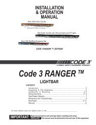
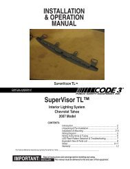
INSTALLATION<br />
& OPERATION<br />
MANUAL<br />
3992 SERIES<br />
SIRENS<br />
SIRENS<br />
Contents:<br />
Introduction ......................................................... 2<br />
Standard Features .............................................. 2<br />
Unpacking & Pre-<strong>Install</strong>ation .............................. 4<br />
<strong>Install</strong>ation & Mounting ....................................... 4<br />
Set-Up and Adjustment ...................................... 7<br />
Operation ............................................................ 8<br />
Maintenance ..................................................... 10<br />
Troubleshooting ................................................ 12<br />
Wiring Diagram ................................................. 14<br />
Specifications.................................................... 15<br />
Parts List ...................................................... 16-19<br />
Warranty ........................................................... 20<br />
IMPORTANT:<br />
Read all instructions and warnings before installing and using.<br />
INSTALLER: This manual must be delivered to the end user of this equipment.
Introduction<br />
The 3992 series sirens are remotely controlled electronic sirens that has been designed to meet the needs of<br />
all emergency vehicles. This series of sirens incorporates the popular features of the existing siren with<br />
microprocessor based circuitry and MOSFET technology. All of the original features are available<br />
along with many added CODE 3 features such as; Park Kill, Instant "ON", Adj. " Scroll " Mode and more.<br />
!<br />
WARNING!<br />
SIREN<br />
PRODUCTS:<br />
<strong>Siren</strong>s are an integral part of an effective audio/visual emergency warning system.<br />
However, sirens are only short range secondary warning devices. The use of a siren<br />
does not insure that all drivers can or will observe or react to an emergency warning<br />
signal, particularly at long distances or when either vehicle is traveling at a high rate of<br />
speed. <strong>Siren</strong>s should only be used in a combination with effective warning lights and<br />
never relied upon as a sole warning signal. Never take the right of way for granted. It is<br />
your responsibility to be sure you can proceed safely before entering an intersection,<br />
driving against traffic, or responding at a high rate of speed.<br />
The effectiveness of this warning device is highly dependent upon correct mounting<br />
and wiring. Read and follow the manufacturer’s instructions before installing or using<br />
this device. The vehicle operator should check the equipment daily to insure that all<br />
features of the device operate correctly.<br />
To be effective, sirens must produce high sound levels that potentially can inflict<br />
hearing damage. <strong>Install</strong>ers should be warned to wear hearing protection, clear bystanders<br />
from the area and not to operate the siren indoors during testing. Vehicle operators<br />
and occupants should assess their exposure to siren noise and determine what steps,<br />
such as consultation with professionals or use of hearing protection should be implemented<br />
to protect their hearing.<br />
This equipment is intended for use by authorized personnel only. It is the user’s<br />
responsibility to understand and obey all laws regarding emergency warning devices. The<br />
user should check all applicable city, state and federal laws and regulations.<br />
<strong>Code</strong> 3, Inc., assumes no liability for any loss resulting from the use of this<br />
warning device.<br />
Proper installation is vital to the performance of the siren and the safe operation of<br />
the emergency vehicle. It is important to recognize that the operator of the emergency<br />
vehicle is under psychological and physiological stress caused by the emergency situation.<br />
The siren system should be installed in such a manner as to: A) Not reduce the<br />
acoustical performance of the system, B) Limit as much as practical the noise level in the<br />
passenger compartment of the vehicle, C) Place the controls within convenient reach of<br />
the operator so that he can operate the system without losing eye contact with the roadway.<br />
Emergency warning devices often require high electrical voltages and/or currents.<br />
Properly protect and use caution around live electrical connections. Grounding or shorting<br />
of electrical connections can cause high current arcing, which can cause personal injury<br />
and/or severe vehicle damage, including fire.<br />
PROPER INSTALLATION COMBINED WITH OPERATOR TRAINING IN THE<br />
PROPER USE OF EMERGENCY WARNING DEVICES IS ESSENTIAL TO INSURE THE<br />
SAFETY OF EMERGENCY PERSONNEL AND THE PUBLIC.<br />
Standard Features<br />
The 3992 series sirens consist of a remotely mounted siren amplifier with an optional second amplifier,<br />
providing up to 400W of siren power and opposing siren tones when both amplifiers are installed. The siren<br />
system is operated by a compact control panel designed to be conveniently mounted near the operator. The<br />
models are as follows:<br />
3992 - Primary Tones: Wail, Yelp, Hi-Lo, Air Horn<br />
- Secondary Tones: HyperYelp, HyperLo<br />
3992XAMP<br />
- Primary Tones: Wail, Yelp, Hi-Lo, Air Horn<br />
- Secondary Tones: HyperYelp, HyperLo<br />
2<br />
2
It is important to note that the 3992XAMP is<br />
compatible with the popular RLS series sirens and<br />
may also be used as a 2nd amplifier with these<br />
sirens.<br />
The following features are standard in the 3992 series<br />
sirens (tones and sequences may differ with model and<br />
options):<br />
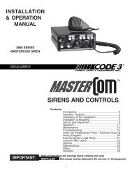
Instant-On- There is no " ON/OFF " switch. Selecting<br />
any<br />
Figure 1 - Control Panel<br />
siren function, or keying the microphone will activate the<br />
selected siren function, assuming the siren is properly installed and the vehicle's ignition is switched on.<br />
Park Kill- This feature deactivates the siren tones when the vehicle is shifted into park. Once PKILL is activated<br />
the siren will remain deactivated until the vehicle is shifted into drive and an<br />
action occurs such as depressing one of the siren control switches or keying the microphone. Any of these<br />
actions will cause the siren tones to start again.<br />
Adjustable Backlighting- Backlighting is independent of siren power. Allows connecting to dimmer if desired.<br />
Automatic Short Circuit Protection- The siren will sense a short circuit on the speaker terminals and<br />
automatically go to standby until the fault is removed. Once the fault is removed the siren will return to normal<br />
operation.<br />
Scroll Mode- Setting the slide switch on the rear of the siren to the SCROLL position will put siren in scroll<br />
mode. This will allow "scrolling" through tones utilizing sharp taps on the horn ring, or a switch, via the Remote<br />
siren input. In this mode holding the horn ring for prolonged durations will produce the Air Horn sound. See<br />
OPERATION section for further details.<br />
Hit-n-Go Mode - Setting the slide switch on the rear of the siren to the Hit-N-Go position will put the siren in the<br />
Hit-n-Go mode. This mode will be most familiar to existing users. A seven second override is<br />
standard for all tones when activated by the Remote input. See OPERATION section for details.<br />
Automatic <strong>Siren</strong> Tones - Industry standard Wail, Yelp, and Hi-Lo tones.<br />
AIR HORN Tone - Electronic AIR HORN sound.<br />
Instant <strong>Public</strong> Address - <strong>Public</strong> Address override of all siren functions when the microphone Push-to-Talk key<br />
is pressed.<br />
Status LED - An indicator LED, visible on the front of the remote siren amplifier indicates that the unit is on<br />
when lighted.<br />
Radio Rebroadcast - Broadcast Two-way radio reception over siren speakers. These inputs are transformer<br />
coupled to prevent loading of the radio.<br />
Remote <strong>Siren</strong> Switching - The siren accepts either a positive or a ground (earth) signal, usually from the<br />
vehicle's horn switch (or other user supplied switch), to remotely activate the MANUAL or AIR HORN functions.<br />
(MANUAL or AIR HORN is selected via the slide switch located on the front panel of the siren amplifier. The<br />
siren is factory set for a GND (Earth) signal and may be reconfigured to accept a positive signal. See<br />
SETUP and Adjustments and Operation sections for details.<br />
Noise Cancelling Microphone - Plug-in microphone that is easily unplugged for service or replacement.<br />
3
Unpacking & Pre-installation<br />
After unpacking your siren, carefully inspect the unit and associated parts for any damage that may<br />
have been caused in transit. Report any damage to the carrier immediately.<br />
<strong>Install</strong>ation & Mounting<br />
The 3992 series siren control may be mounted above the dash, below the dash, on a tunnel or in a rack with<br />
the mounting hardware supplied (see Fig. 1). Ease of operation and convenience to the operator should be<br />
the prime consideration when mounting the siren and controls<br />
.<br />
NOTE: Setups and<br />
adjustments will be made in<br />
subsequent steps. That may<br />
require access to the rear area<br />
of the unit. Plan the installation<br />
and wiring accordingly.<br />
Figure 1<br />
!<br />
WARNING!<br />
All devices should be mounted in accordance with the manufacturer’s<br />
instructions and securely fastened to vehicle elements of sufficient strength to<br />
withstand the forces applied to the device. Ease of operation and convenience to the<br />
operator should be the prime consideration when mounting the siren and controls.<br />
Adjust the mounting angle to allow maximum operator visibility. Do not mount the<br />
Control Head Module in a location that will obstruct the drivers view. Mount the<br />
microphone clip in a convenient location to allow the operator easy access. Devices<br />
should be mounted only in locations that conform to their SAE identification code as<br />
described in SAE Standard J1849. For example, electronics designed for interior<br />
mounting should not be placed underhood, etc.<br />
Controls should be placed within convenient reach* of the driver or if intended<br />
for two person operation the driver and/or passenger. In some vehicles, multiple<br />
control switches and/or using methods such as “horn ring transfer” which utilizes the<br />
vehicle horn switch to toggle between siren tones may be necessary for convenient<br />
operation from two positions.<br />
4
Amplifier Connections<br />
<strong>Siren</strong> Amplifier Connector - As a standard feature, the <strong>Siren</strong> is equipped with a combination plugin<br />
terminal block/connector. To terminate the wires, strip approximately 1/4" of insulation from the<br />
end of each wire and insert it in the appropriate hole in the terminal block. Tighten the setscrew and<br />
proceed to the next connection.<br />
Should you ever have to remove the unit, pull the terminal block straight out. It will unplug from the<br />
unit, leaving the wiring in place.<br />
Terminal Connections<br />
COM - Connect to the wire from speaker terminal 1.<br />
SPKR - Speaker - Connect to the wire from speaker terminal 2.<br />
!<br />
WARNING!<br />
Larger wires and tight connections will provide longer service life for components. For high<br />
current wires it is highly recommended that terminal blocks or soldered connections be used with<br />
shrink tubing to protect the connections. Do not use insulation displacement connectors(e.g. 3M ® )<br />
Scotchlock type connectors). Route wiring using grommets and sealant when passing through<br />
compartment walls. Minimize the number of splices to reduce voltage drop. High ambient<br />
temperatures (e.g. underhood) will significantly reduce the current carrying capacity of wires, fuses,<br />
and circuit breakers. Use "SXL" type wire in engine compartment. All wiring should conform to the<br />
minimum wire size and otherrecommendations of the manufacturer and be protected from moving<br />
parts and hot surfaces. Looms, grommets, cable ties, and similar installation hardware should be<br />
used to anchor and protect all wiring.<br />
Fuses or circuit breakers should be located as close to the power takeoff points as possible<br />
and properly sized to protect the wiring and devices. Particular attention should be paid to the<br />
location and method of making electrical connections and splices to protect these points from<br />
corrosion and loss of conductivity. Ground (Earth) terminations should only be made to substantial<br />
chassis components, preferably directly to the vehicle battery.<br />
The user should install a circuit breaker sized to approximately 125% of the maximum Amp capacity<br />
in the supply line to protect against short circuits. For example, a 30 Amp circuit breaker should<br />
carry a maximum of 24 Amps.<br />
DO NOT USE 1/4" DIAMETER GLASS FUSES AS THEY ARE NOT SUITABLE FOR<br />
CONTINUOUS DUTY IN SIZES ABOVE 15 AMPS. Circuit breakers are very sensitive to high<br />
temperatures and will "false trip" when mounted in hot environments or operated close to their<br />
capacity.<br />
NOTE: When using two 100W (11 ohm) speakers in parallel, correct phasing is important and can<br />
be accomplished by connecting both speaker terminals marked " 1 " to the COM terminal and both<br />
speaker terminals marked " 2" to the SPKR terminal. Also refer to the wiring diagram on page 14.<br />
REMOTE - Remote switch (Horn ring or foot switch). Circuit can be configured for both ground<br />
(earth) or positive signals. A horn ring transfer circuit is standard in all 3990 series. Connect to the<br />
"REMOTE" terminal on the Lighting Control Section terminal block. Unit is configured for a ground<br />
(earth) at the factory. See page 8 for details on configuring for a +12V input.<br />
5
!<br />
WARNING!<br />
CONNECTION OF A 58 WATT SPEAKER TO THE SPKR TERMINAL WILL CAUSE<br />
THE SPEAKER TO BURN OUT, AND WILL VOID THE SPEAKER WARRANTY!<br />
The sound projecting opening should be pointed forward, parallel to the ground, and not<br />
obstructed or muffled by structural components of the vehicle. Concealed or underhood<br />
mountings in some cases will result in a dramatic reduction in performance. To minimize this<br />
reduction, mount the speaker so the sound emitted is projected directly forward and obstruction<br />
by vehicle components such as hoses, brackets, grille, etc. is minimized.<br />
Electromechanical sirens and electronic siren speakers should be mounted as far from<br />
the occupants as possible using acoustically insulated compartments and isolation mountings to<br />
minimize the transmission of sound into the vehicle. It may be helpful to mount the device on<br />
the front bumper, engine cowl or fender; heavily insulate the passenger compartment; and<br />
operate the siren only with the windows closed.<br />
Each of these approaches may cause significant operational problems, including loss of siren<br />
performance from road slush, increased likelihood of damage to the siren in minor collisions,<br />
and the inability to hear the sirens on other emergency vehicles.<br />
APPROPRIATE TRAINING OF VEHICLE OPERATORS IS RECOMMENDED TO<br />
ALERT THEM TO THESE PROBLEMS AND MINIMIZE THE EFFECT OF THESE PROBLEMS<br />
DURING OPERATIONS.<br />
BLTG- Provides +12V to siren backlighting. Connect to a vehicle circuit that is powered when the<br />
ignition switch is " on ". If backlighting dimming is desired, connect to the dash lights' circuit.<br />
Caution- If connected to the battery the backlighting will be active at all times.<br />
PKILL- This feature automatically deactivates siren tones when the vehicle is shifted into PARK.<br />
<strong>Siren</strong> tones will be disabled until the vehicle is shifted out of PARK and one of the siren control<br />
switches is selected. This circuit is activated by a negative signal. Connect this input to a circuit<br />
that is GROUNDED (Earth) when the vehicle is shifted into PARK. It is the installer's<br />
responsibility to determine an appropriate location in the vehicle circuitry to connect this<br />
wire.<br />
RRB - Connect to one side of the two-way radio speaker.<br />
RRB - Connect to the second side of the two-way radio speaker.<br />
InterClear ® - Connect to the device or circuit that is to be activated by the InterClear feature. The<br />
InterClear circuit is internally current limited at 1 Amp. Should your application require higher<br />
currents, use the InterClear Power Booster Kit (# INTBS), available from your <strong>Code</strong> 3 supplier.<br />
Power Connections<br />
1/4" Male Quick-Connect Printed Circuit Board Terminals<br />
+12V - Connect to a positive +12 volt DC source. It is recommended that the user protect this wire<br />
with a 20 Amp fuse or circuit breaker located at the source. Use #14 gauge wire terminated with 1/<br />
4" female, fully insulated quick-connect terminals only.<br />
NEG - Connect to the negative terminal of the battery. This supplies ground (earth) to the siren. Use<br />
#14 gauge wire terminated with 1/4" female, fully insulated quick-connect terminals only.<br />
NOTE: A #8 stud is provided on the rear of the unit and is intended for use ONLY as a convenient<br />
ground (earth) " tie-point " for the light bar wiring. It is not an adequate ground (earth) for the<br />
siren or the light bar. It is recommended all ground (earth) wires attached here be<br />
terminated with a crimp-on ring terminal.<br />
6
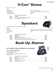
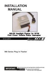
When using the 3992XAMP 2nd amplifier with the 3992 siren system the RLSEXP Modular<br />
Expansion unit is required. Refer to the diagram on page 11 for interconnection details.<br />
The 3992XAMP may also be used with the RLS 3997, 3998 and 3999 sirens by using the same<br />
basic interconnection method shown on page 11.<br />
SETUP AND ADJUSTMENT<br />
All of the adjustments and setup switches are located on the amplifier unit. Make these<br />
adjustments and set the switches to the desired position prior to securing the amplifier in it's final<br />
mounting location. (see wiring diagram, page 15).<br />
Audio Adjustments<br />
Radio Rebroadcast Adjustment - Place the selector switch in the RADIO position. The trimmer<br />
located on the rear panel of the siren sets the maximum level RRB will reach with the knob fully<br />
clockwise. To adjust properly, set the volume knob fully clockwise and adjust the trimmer such that<br />
normal two-way radio volume inside the vehicle produces the desired volume outside the vehicle.<br />
Maximum P.A. Volume Adjustment - This trimmer (located on the front panel next to the volume<br />
control knob) sets the maximum level that the P.A. volume<br />
will reach with the front panel VOLUME control in the fully<br />
clockwise position. To adjust properly, set the front panel<br />
volume control fully clockwise and adjust the trimmer<br />
while keying the microphone until the maximum volume<br />
out of the speaker is such that there is no feedback and is<br />
intelligible.<br />
Remote Input - The remote input can be configured to<br />
accept either a positive +12V or negative GND ( Earth )<br />
signal for actuation. All 3990 series sirens are shipped<br />
setup to accept the GND (Earth) signal present on most<br />
vehicles from the vehicle horn switch. To reconfigure the<br />
Remote Input to accept a +12V signal the amplifier cover<br />
must be removed (see exploded view, page 20). Move<br />
both jumpers towards the "+ " position. Refer to detail "A"<br />
for a complete illustration.<br />
<strong>Siren</strong> Mode Selector Switch (located on the siren<br />
amplifier, rear panel)<br />
The siren has two distinct modes, Hit-N-Go and Scroll. Set<br />
rear panel slide switch, Figure 2, to the desired mode by<br />
sliding left or right. See operation section for a detailed<br />
description of operation in each mode.<br />
RRB MAX<br />
V OL.<br />
ADJ.<br />
TI E POINT ONLY<br />
DO NOT USE FOR<br />
SIREN OR<br />
LI GHTBAR<br />
GROUND<br />
SIREN FUSE<br />
20A ONLY<br />
Model:<br />
USE<br />
QU<br />
+12<br />
P.A. Volume Knob<br />
Figure 2<br />
Amplifier Rear View<br />
Hit-N-Go / Scroll Switch<br />
This control adjusts the level of the P.A. audio produced<br />
when keying the microphone and speaking into it. This control also controls the Radio Rebroadcast<br />
level when in the " RRB " switch is on. (see SETUP, Radio Rebroadcast Adjustment).<br />
7
Operation<br />
IMPORTANT !<br />
The Model 3992 <strong>Siren</strong> has two distinct modes of operation. These are Hit-N-Go mode and<br />
SCROLL mode. The desired mode of operation can be selected via the amplifier rear panel slide<br />
switch. Each mode will affect the siren operation as described below. The Hit-N-Go mode should be<br />
most familiar to existing users.<br />
The Park Kill features will, in some cases, prevent the siren from producing siren tones. The<br />
siren will not produce tones when the vehicle is in "PARK" if the PKILL feature has been connected.<br />
To test the siren tones the vehicle must not be in "PARK". The following assumes that PKILL has not<br />
been activated.<br />
Operation - Hit-N-Go Mode Selected<br />
The Hit-N-Go mode is designed to allow the user to instantly change siren tones by utilizing the<br />
Remote input on the siren. By depressing the switch connected to the Remote input of the siren (usually the<br />
vehicle Horn Ring switch), the user can cause the siren to change tones for an eight second period after<br />
which time the siren will revert to the previous tone. The InterClear output will also be activated during this<br />
period.<br />
Function Description<br />
RRB - In the RADIO position, the audio from the 2-way radio is rebroadcast over the siren speaker.<br />
Note, all siren tone functions are disabled in this mode. Hhowever, the AIRHORN function will operate<br />
normally.<br />
STANDBY - This is the standby mode. If the MANUAL button is depressed the Manual wail tone will<br />
ramp up until it reaches a peak then ramp down when released. If the AIR HORN button is depressed,<br />
the Air Horn sound will be produced.<br />
WAIL - Rotating the selector switch to the WAIL position will cause the siren to produce the Wail<br />
tone. Depressing the AIR HORN button will produce the Air Horn sound and when released the siren will<br />
resume the Wail tone. If the MANUAL button is depressed the Manual wail tone will ramp up until it<br />
reaches a peak then ramp down when released then resume the selected tone. The Remote/Horn Ring<br />
input will activate the Interclear output and cause the siren tone to either scroll to the next mode or change to<br />
Yelp for 7 seconds, depending on the position of the SCROLL/HIT&GO switch.<br />
YELP - Rotating the selector switch to the YELP position will cause the siren to produce the Yelp<br />
tone. Depressing the AIR HORN button will produce the Air Horn sound and when released the siren will<br />
resume the Yelp tone. If the MANUAL button is depressed the Manual wail tone will ramp up until it<br />
reaches a peak then ramp down when released then resume the selected tone. The Remote/Horn Ring<br />
input will activate the Interclear output and cause the siren tone to either scroll to the next mode or change to<br />
HyperYelp for 7 seconds, depending on the position of the SCROLL/HIT&GO switch.<br />
HI-LO - Rotating the selector switch to the HILO position will cause the siren to produce the HILO<br />
tone. Depressing the AIR HORN button will produce the Air Horn sound and when released the siren will<br />
resume the HILO tone. If the MANUAL button is depressed the Manual wail tone will ramp up until it reaches<br />
a peak then ramp down when released then resume the selected tone. The Remote/Horn Ring input will<br />
activate the Interclear output and cause the siren tone to either scroll to the next mode or change to HyperLO<br />
for 7 seconds, depending on the position of the SCROLL/HIT&GO switch.<br />
8
Push-to-Talk (PTT) Microphone Switch - Keying<br />
the microphone will automatically override whatever mode<br />
the siren is in and broadcast public address messages<br />
over the siren speaker.<br />
Max PA Volume<br />
MANUAL Push-button Momentary Switch -<br />
Produces the Manual tone as described above.<br />
AIR HORN Pushbutton Momentary Switch -<br />
Produces the Air Horn tone as described above.<br />
Manual Air Horn PA Volume<br />
Figure 3, <strong>Siren</strong> Amplifier, Front Panel<br />
!<br />
WARNING!<br />
"Wail" and "Yelp" tones are in some cases (such as in the state of California)<br />
the only recognized siren tones for calling for the right of way. Ancillary tones<br />
such as "Air Horn", "Hi-Lo", "Hyperyelp", and "Hyperlo" in some cases do not<br />
provide as high a sound pressure level. It is recommended that these tones be<br />
used in a secondary mode to alert motorists to the presence of an emergency<br />
vehicle.<br />
SLIDE SWITCH (Manual / AIR HORN) - The slide switch located on the front of the siren amplifier<br />
(see Figure 3) selects the function for the REMOTE (external switch) circuitry. When the siren is in standby<br />
mode and switch is to the right, the Horn Ring circuitry remotely "depresses" the AIR HORN button and it<br />
produces the effects outlined above. When the slide switch is to the left, it allows the REMOTE circuitry to<br />
remotely "depress" the MANUAL push-button with a similar result.<br />
Operation - Scroll Mode Selected<br />
The " Scroll " mode is designed to allow the user to scroll through Wail, Yelp, HyperYelp and AIR<br />
HORN tones by utilizing the Remote input on the siren. This will usually be connected to the vehicle Horn<br />
Ring circuit. The user can use the Horn Ring to sequence through Wail, Yelp and Hyperyelp by applying a<br />
quick, sharp tap on the horn. Additional taps will scroll the siren to the next tone. The InterClear output will<br />
also be activated for an eight second period following each tap of the Horn Ring switch. Depressing the horn<br />
for longer periods will produce AIR HORN tone and deactivate the InterClear output.<br />
When the Scroll Off option is purchased, the Remote input may be used to activate the siren from the<br />
Standby mode. In this case the Scroll feature will operate as described above except that the siren will scroll<br />
through WAIL, YELP, HYPERYELP & STANDBY modes. Holding the remote switch for a longer period will<br />
still cause the siren to switch to the Air Horn tone. When the siren is not in Standby mode (the siren is<br />
operating in any mode which was invoked by the either the Scroll Up or Scroll Down switches on the 3992<br />
control panel), the scroll feature will operate as previously described.<br />
Function Description<br />
RRB - In the RRB position, the audio from the 2-way radio is rebroadcast over the siren speaker.<br />
Note, all siren tone functions are disabled in this mode. Hhowever, the AIRHORN function will operate<br />
normally.<br />
STANDBY - This is the standby mode; no siren tones are produced in this position except when the<br />
MANUAL button is depressed the Manual wail tone will ramp up until it reaches a peak then ramp down when<br />
released. If the AIR HORN button is depressed, the Air Horn sound will be produced.<br />
9
WAIL - This mode produces the Wail tone. Depressing the MANUAL button will now produce Manual<br />
wail tone and ramp up until released. Depressing the AIR HORN button will produce the Air Horn sound. The<br />
siren can be scrolled in this position as described above. The Remote/Horn Ring input will also activate the<br />
Interclear output for 7 seconds.<br />
YELP - This mode produces the Yelp tone. Pushing the MANUAL button will now produce the<br />
Manual wail tone and ramp up until released. If the AIR HORN button is pushed, the AIR HORN sound will be<br />
produced. The siren can be scrolled from this position as described above. The Remote/Horn Ring<br />
input will also activate the Interclear output for 7 seconds.<br />
HI-LO - This position produces the Hi-Lo tone. Pushing the MANUAL button will produce the Manual<br />
Wail tone until released. If the AIR HORN button is pushed, the AIR HORN sound will be produced and when<br />
released the siren return to Hi-Lo. The siren cannot be scrolled from this position. The Remote/Horn Ring<br />
input will activate the Interclear output and cause the tone to change to HyperLo for 7 seconds.<br />
Push-to-Talk (PTT) Microphone Switch - Keying the microphone will automatically override<br />
whatever mode the siren is in and broadcast public address messages over the siren speaker.<br />
MANUAL Pushbutton Momentary Switch - Produces the Manual tone as described above.<br />
AIR HORN Pushbutton Momentary Switch - Produces the Air Horn tone as described above.<br />
MANUAL / AIR HORN SWITCH - The MANUAL / AIR HORN slide switch located on the front of the<br />
siren amplifier, Figure 3, selects the function for the REMOTE (external switch) circuitry when the siren is in<br />
standby mode. When the siren is in standby mode and switch is to the right, the Horn Ring circuitry remotely<br />
"depresses" the AIR HORN button and it produces the effects outlined above. When the slide switch is to the<br />
left, it allows the REMOTE circuitry to remotely "depress" the MANUAL pushbutton. This causes the effects<br />
described above to occur. When in the "Scroll " mode this switch has no effect unless in STANDBY<br />
position.<br />
LED STATUS INDICATOR - The green LED status indicator indicates the siren amplifier is on when<br />
lighted; off or standby mode when unlighted.<br />
SPECIAL CAUTION!<br />
The modular cables supplied with the siren are specially designed to meet the needs of this<br />
product. DO NOT attempt to splice the cables, fabricate replacement cables or to substitute generic<br />
cables in place of those provided. Use of non-CODE 3 cables will cause damage to your siren and will<br />
void the warranty. CODE 3 has several lengths of standard cables available and can fabricate custom<br />
length cables (priced separatley) to meet your unique requirements.<br />
MAINTENANCE<br />
Your <strong>Code</strong> 3 ® 3992 siren has been designed to provide trouble free service. In case of difficulty, see<br />
Troubleshooting (pages 12-13). Also check for shorted or open wires. The primary cause of short circuits<br />
has been found to be wires passing through firewalls, roofs, etc. If further difficulty persists, contact the<br />
factory for troubleshooting advice or return instructions. <strong>Public</strong> <strong>Safety</strong> <strong>Equipment</strong>, Inc. maintains a complete<br />
parts inventory and service facility at the factory and will repair or replace (at the factory's option) any unit<br />
found to be defective under normal use and in warranty. Any attempt to service a unit in warranty by anyone<br />
other than a factory authorized technician without express written consent by the factory, will void the<br />
warranty. Units out of warranty can be repaired at the factory for a nominal charge on either a flat rate or<br />
parts and labor basis. Contact the factory for details and return instructions. <strong>Public</strong> <strong>Safety</strong> <strong>Equipment</strong>, Inc. is<br />
not liable for any incidental charges related to the repair or replacement of a unit unless otherwise expressly<br />
agreed to in writing.<br />
10
11<br />
3992/ 3992XAMP Interconnection
TROUBLESHOOTING<br />
(Refer to wiring diagram page 15)<br />
PROBLEM PROBABLE CAUSE REMEDY<br />
NO SIREN OUTPUT.<br />
EXTERNAL 20A<br />
FUSE BLOWS.<br />
A. PARK KILL ACTIVATED<br />
B. SHORTED SPEAKER OR<br />
SPEAKER WIRES. SIREN IN<br />
OVER CURRENT PROTECTION<br />
MODE.<br />
A. AMPLIFIER POWER WIRES<br />
REVERSED POLARITY<br />
A. SHIFT VEHICLE OUT<br />
OF PARK.<br />
B. REPLACE<br />
SPEAKERS, CHECK<br />
CONNECTIONS<br />
A. CHECK POLARITY<br />
NO OUTPUT FROM<br />
SPEAKER, TONES<br />
HEARD INSIDE<br />
AMP. MODULE.<br />
SIREN TONES<br />
VOLUME TOO<br />
LOW/GARBLED.<br />
HIGH RATE OF<br />
SPEAKER FAILURE.<br />
A. SPEAKER NOT CONNECTED/<br />
OPEN CIRCUIT IN SPEAKER<br />
WIRING<br />
B. DEFECTIVE SPEAKERS<br />
A. LOW VOLTAGE TO SIREN<br />
AMPLIFIER<br />
B. HIGH RESISTANCE IN WIRING/<br />
DEFECTIVE SPEAKER<br />
C. SPEAKERS PHASED<br />
IMPROPERLY<br />
A. HIGH VOLTAGE TO SIREN<br />
B. 58 WATT SPEAKER CONNECTED<br />
A. CHECK SPEAKER<br />
WIRING<br />
B. REPLACE<br />
SPEAKER(S)<br />
A. CHECK WIRING FOR<br />
BAD CONNECTIONS/<br />
CHECK VEHICLE<br />
CHARGING SYSTEM<br />
B. CHECK SPEAKER(S)<br />
WIRING/REPLACE<br />
SPEAKER(S)<br />
C. REFER TO TEXT<br />
FOR PROPER<br />
PHASING<br />
A. CHECK VEHICLE<br />
CHARGING SYSTEM<br />
B. USE CORRECT<br />
SPEAKER<br />
SIREN CONTINUES<br />
TO OPERATE FOR<br />
7 SEC. AFTER<br />
MANUAL BUTTON/<br />
HORN RING IS<br />
RELEASED.<br />
INTERCLEAR WILL NOT<br />
POWER AUXILIARY<br />
DEVICES.<br />
P.A. VOLUME LOW OR<br />
NO P.A. AT ALL.<br />
VOLUME CONTROL<br />
FULLY CLOCKWISE.<br />
A. "HIT-N-GO" FEATURE ENGAGED.<br />
NORMAL OPERATION<br />
A. THERE IS A SHORT IN THE<br />
WIRING, OR THE LOAD IS<br />
GREATER THAN 1 A.<br />
A. DEFECTIVE MICROPHONE<br />
B. MAXIMUM P.A. VOLUME<br />
TRIMMER MISADJUSTED. SEE<br />
SETUP AND ADJUSTMENT<br />
SECTION.<br />
C. MICROPHONE NOT<br />
COMPLETELY PLUGGED IN.<br />
D. COMMON MICROPHONE<br />
CIRCUIT NOT PROPERLY WIRED.<br />
E. INCORRECT MICROPHONE.<br />
12<br />
A. CHECK FOR<br />
SHORTS. INSTALL<br />
INTERCLEAR<br />
BOOSTER KIT (PART<br />
#INTBS)<br />
A. REPLACE<br />
MICROPHONE<br />
B. REFER TO SETUP<br />
AND ADJUSTMENT<br />
SECTION<br />
C. PLUG MICROPHONE<br />
IN SECURELY<br />
D. CHECK WIRING<br />
E. CALL PSE FOR LIST<br />
OF ADAPTABLE<br />
MICROPHONES
TROUBLESHOOTING<br />
(Refer to wiring diagram page 15)<br />
PROBLEM PROBABLE CAUSE REMEDY<br />
RRB VOLUME LOW, OR<br />
NO RRB AT ALL.<br />
VOLUME CONTROL<br />
FULLY CLOCKWISE.<br />
A. MAXIMUM RADIO<br />
REBROADCAST TRIMMER<br />
MISADJUSTED<br />
B. RRB WIRES NOT CONNECTED<br />
TO TWO-WAY RADIO EXTERNAL<br />
SPEAKER<br />
A. REFER TO SETUP<br />
AND ADJUSTMENT<br />
SECTION<br />
B. CHECK RRB<br />
CONNECTIONS<br />
SIREN SOUNDS BY<br />
ITSELF<br />
A. REMOTE SWITCH (HORN RING)<br />
WIRING FROM TERMINAL REMOTE<br />
SHORTING TO POSITIVE OR TO<br />
GROUND (EARTH).<br />
A. CHECK WIRING FOR<br />
ANY SHORTING.<br />
SIREN RUNS<br />
PROPERLY BUT<br />
SHUTS DOWN WHILE<br />
RUNNING, THEN<br />
STARTS RUNNING<br />
AGAIN AFTER A FEW<br />
MINUTES<br />
A. VEHICLE CIRCUIT BREAKERS<br />
NOT RATED PROPERLY, AND ARE<br />
OVERHEATING, OR ARE NOT<br />
FUNCTIONING PROPERLY<br />
A. REFER TO<br />
SPECIFICATIONS<br />
SECTION, PAGE 17.<br />
USE A BREAKER<br />
RATED AT 1.25x THE<br />
AMPERAGE OF THE<br />
EXPECTED LOAD<br />
CURRENT.<br />
13
Cod e3<br />
Publ ic<br />
afet<br />
asubsidi<br />
Equipm<br />
ary<br />
nt<br />
of<br />
In c.<br />
W<br />
MA<br />
C o de 3<br />
P ublic<br />
Inc.,<br />
afet<br />
a sub sid iary<br />
E q uipm ent ,<br />
I o<br />
nc<br />
f<br />
S , .<br />
R<br />
WAR NIN G<br />
W<br />
AX .<br />
M AX. S PEAKER<br />
M CU<br />
OAD 2 00 W ATT<br />
L A<br />
R<br />
LO<br />
,<br />
A R NIN !<br />
XA S PEA ER<br />
2 00 ATT<br />
Ḋ<br />
In c.,<br />
W<br />
MA X .<br />
C U<br />
o<br />
del : 3992<br />
R R B MAX<br />
V O L . ADJ .<br />
M<br />
TIE P O INT O NLY<br />
DO N ONTN TU S EFOR<br />
SIR E OR<br />
LIG HO BAR<br />
GR U D<br />
SIREN<br />
20A O<br />
WA RNIN G<br />
U S E ONLY INSU L<br />
QU<br />
ICKSLIDES FO<br />
R<br />
+ 12 V & NEG TE<br />
RM<br />
S<br />
+12V<br />
N EG<br />
!<br />
A ED<br />
USE 1/4" FEMALE INSULATED<br />
QUICK-CONNECTS<br />
BATTERY<br />
20A MAX<br />
TO IGNITION<br />
M o d el : 3992XAMP<br />
B R<br />
A R NI N G!<br />
INTER<br />
CLEAR<br />
TIE P O INT ONLY<br />
RENT<br />
- 1A<br />
DO N T S<br />
E FOR<br />
SIR L<br />
E<br />
B G IG<br />
ROU<br />
H<br />
N O T<br />
N D A R<br />
E<br />
B R MAX<br />
SIR N<br />
A DJ .<br />
20A ONL Y<br />
V R O R L B U<br />
Q+<br />
S<br />
WA RNIN G<br />
ONLY INSU L<br />
! A T E D<br />
U ICKSLIDES F O R<br />
2 V & NEG T E R M S<br />
1<br />
E<br />
,<br />
S<br />
y<br />
G<br />
KW<br />
y<br />
!<br />
e<br />
.<br />
T<br />
16GA<br />
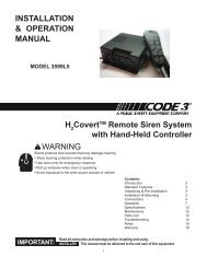
COM<br />
18 GA<br />
+12V<br />
BREAK VEHICLE<br />
ADDITIONAL 100W SPEAKER<br />
100W SPEAKER<br />
- +<br />
}<br />
INTERCLEAR OUTPUT #1, 1A Maximum<br />
TO TWO-WAY RADIO<br />
PARK SWITCH<br />
DASH LIGHT SWITCH / IGNITION<br />
SWITCH<br />
#14 GA<br />
16GA<br />
1 1<br />
2 2<br />
INTERCLEAR OUTPUT #2, 1A Maximum<br />
INTERCONNECT DIAGRAM<br />
COM<br />
1 1<br />
2 2<br />
#14 GA<br />
20A MAX<br />
TO IGNITION<br />
14
Specifications, 3992 / 3992XAMP <strong>Siren</strong>s<br />
Input Voltage:<br />
10 to 16 VDC, negative ground - 12V units<br />
(Note: Operation above 15 VDC for an extended period of time may result in speaker damage.)<br />
20 to 30 VDC, negative ground - 24V units<br />
(Note: Operation above 30 VDC for an extended period of time may result in speaker damage.)<br />
Operating Current 100W: 8 Amps @ 13.6V with 11-ohm load ( 100 W Spkr ) - 12Vunits<br />
4. 5 Amps @ 27.6V with 11-ohm load ( 100 W Spkr ) - 24Vunits<br />
200W:<br />
14 Amps @ 13.6V with 5.5-ohm load ( 2- 100 W Spkr ) - 12V units<br />
9 Amps @ 27.6V with 5.5-ohm load ( 2- 100 W Spkr ) - 24V units<br />
Standby Current: 25 mA excluding backlighting<br />
Cycle Rate: WAIL - 11 cycles/minute.<br />
YELP - 200 cycles/minute.<br />
Voltage Output ( approx. ) 58V peak-to-peak with 5.5 ohm load ( 2-100 W Spkrs )<br />
Primary Tones: (standard)<br />
Secondary Tones: (standard)<br />
Primary Tones: (optional)<br />
Secondary Tones: (optional)<br />
Wail, Yelp, Hi-Lo, Air Horn<br />
HyperYelp, HyperLo<br />
Wail, Yelp, Air Horn<br />
HyperYelp<br />
Note: The 3992XAMP provides opposing tones for use in dual siren applications:<br />
3992 Tone 3992XAMP Tone<br />
Wail<br />
Wail<br />
Yelp<br />
Wail<br />
HyperYelp Yelp<br />
HILO Yelp*<br />
HyperLo** Yelp<br />
Manual Manual<br />
Air Horn<br />
Air Horn<br />
*Yelp Yelp w/ No HILO option<br />
**The HyperLo tone is produced by the 3992 siren in Hit&Go mode only.<br />
Audio Section:<br />
Noise Cancelling Plug-In Microphone<br />
Audio Response: ± 1 dB 300 to 3000 hz.<br />
1000 hz. 0 dB Reference<br />
Special Features:<br />
Instant “ON”, Park Kill, Adj. Backlighting, “Hit&Go” Mode, “Scroll” Mode w/ Instant Air Horn, “Scroll-Off” Mode<br />
w/Instant Air Horn (optional), Automatic Short Circuit Protection, Instant <strong>Public</strong> Address, Status Indicator LED,<br />
Radio Rebroadcast (RRB), Remote <strong>Siren</strong> Switching Input (Horn Ring or Remote Switch), +12VDC or Ground<br />
operation<br />
Dimensions and Weight:<br />
Control Head: 4.625"W x 2.625"H x 1.9"D, Mounting Hole Centers: 2.250"<br />
Amplifier: 7.625"W x 2.5"H x 7.0"D, Mounting Hole Centers: 7.125" x 4.375"<br />
Standard Control Cable Length: 20 Feet<br />
Shipping Weight (3992) 5.75 lbs; (3992XAMP) 4 lbs<br />
15
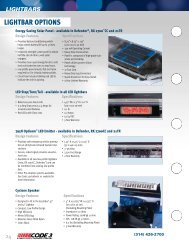
16<br />
Control Head, Exploded View
<strong>Siren</strong> Control Head, Parts List<br />
Ref No. Description Part No. Qty.<br />
1 Label, Faceplate, Model 3992 <strong>Siren</strong> T11069 1<br />
2 Enclosure, Control Head, Model 3992 <strong>Siren</strong> T11043 1<br />
3 Washer, 3/8" Flat, Volume Control T00667 1<br />
4 Nut, 3/8-32 x 1/2" x .090" T01082 5<br />
5a Knob, Selector Switch T03537 1<br />
5b Insert, Knob, Selector Switch T03538 1<br />
6 4-40 x 3/8" Pan Head Phillips, Black Oxide T06937 5<br />
7 PCB Assembly, Control Head, Model 3992 <strong>Siren</strong> S71646 1<br />
8 E-Tray, Control Head, Model 3992 <strong>Siren</strong> T11046 1<br />
9 Bracket, Control Head, Model 3992 <strong>Siren</strong> T11050 2<br />
10 8-32 x 1/4" Hex Head, Zinc T01385 2<br />
11 1/4 - 20 x .375", Hex Washer Hd, Zinc T10912 2<br />
17
<strong>Siren</strong> Amplifier, Exploded View<br />
18
<strong>Siren</strong> Amplifier, Parts List<br />
Ref No. Description Part No. Qty.<br />
1 3/8 - 32 x 1/2 x .090" Nut T01082 2<br />
2 Flat Washer, 3/8" T00667 2<br />
3 8 - 32 Keps Nut T00674 2<br />
4 8 - 32 x 5/8 Machine Screw T00763 1<br />
5 6 - 32 Rd Hd Phil., Machine Screw T01030 6<br />
6 6 x 3/8 Hex Hd, Sheet Metal Screw T01031 1<br />
7 Tinnerman Clip T01058 1<br />
8 4 - 40 Nylon Insert Stop Nut T03594 2<br />
9 Fuse, ATO, 20A T01143 1<br />
10 Transistor Insulating Pad T06363 2<br />
11 Serial Number Label T06140 1<br />
12 Airbag Warning Label T09937 1<br />
13 Label, Wiring and Backplate, Model 3992 <strong>Siren</strong> T11047 1<br />
14 E - Tray, Inserted T11052 1<br />
15 Cover, Model 3992 <strong>Siren</strong> Amplifier T11053 1<br />
16 <strong>Siren</strong> Amplifier PCB, RLS Series <strong>Siren</strong> S71541 1<br />
Not Shown:<br />
#6-32 x 1.5, Truss Hd., Phil., Machine Screw T11136 4<br />
19
WARRANTY<br />
<strong>Code</strong> 3, Inc.'s emergency devices are tested and found to be operational at the time of<br />
manufacture. Provided they are installed and operated in accordance with manufacturer's<br />
recommendations, <strong>Code</strong> 3, Inc. guarantees all parts and components except the lamps to a period<br />
of 1 year (unless otherwise expressed) from the date of purchase or delivery, whichever is later.<br />
Units demonstrated to be defective within the warranty period will be repaired or replaced at the<br />
factory service center at no cost.<br />
Use of lamp or other electrical load of a wattage higher than installed or recommended by<br />
the factory, or use of inappropriate or inadequate wiring or circuit protection causes this warranty<br />
to become void. Failure or destruction of the product resulting from abuse or unusual use and/<br />
or accidents is not covered by this warranty. <strong>Code</strong> 3, Inc. shall in no way be liable for other<br />
damages including consequential, indirect or special damages whether loss is due to negligence<br />
or breach of warranty.<br />
CODE 3, INC. MAKES NO OTHER EXPRESS OR IMPLIED WARRANTY INCLUDING,<br />
WITHOUT LIMITATION, WARRANTIES OF FITNESS OR MERCHANTABILITY, WITH<br />
RESPECT TO THIS PRODUCT.<br />
PRODUCT RETURNS<br />
If a product must be returned for repair or replacement*, please contact our factory to<br />
obtain a Return Goods Authorization Number (RGA number) before you ship the product to<br />
<strong>Code</strong> 3, Inc. Write the RGA number clearly on the package near the mailing label. Be sure you<br />
use sufficient packing materials to avoid damage to the product being returned while in transit.<br />
*<strong>Code</strong> 3, Inc. reserves the right to repair or replace at its discretion. <strong>Code</strong> 3, Inc. assumes no responsibility or liability for expenses incurred for<br />
the removal and /or reinstallation of products requiring service and/or repair.; nor for the packaging, handling, and shipping: nor for the handling of<br />
products return to sender after the service has been rendered.<br />
NEED HELP? Call our Technical Assistance Hotline - (314) 996-2800<br />
<strong>Code</strong> 3, Inc.<br />
10986 N. Warson Road<br />
St. Louis, Missouri 63114-2029—USA<br />
www.code3pse.com<br />
<strong>Code</strong> 3 is a registered trademark of <strong>Code</strong> 3, Inc. a subsidiary of <strong>Public</strong> <strong>Safety</strong> <strong>Equipment</strong>, Inc.<br />
Revision 5, 01/2006 - Instruction Book Part No. T11048<br />
©2004 <strong>Code</strong> 3, Inc. Printed in USA<br />
20