
Create successful ePaper yourself
Turn your PDF publications into a flip-book with our unique Google optimized e-Paper software.
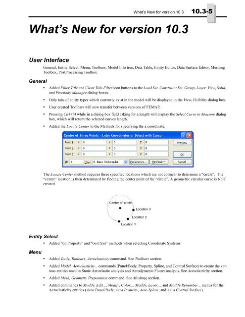
What’s <strong>New</strong> <strong>for</strong> <strong>version</strong> <strong>10.3</strong> <strong>10.3</strong>-5<br />
What’s <strong>New</strong> <strong>for</strong> <strong>version</strong> <strong>10.3</strong><br />
User Interface<br />
General<br />
General, Entity Select, Menu, Toolbars, Model Info tree, Data Table, Entity Editor, Data Surface Editor, Meshing<br />
Toolbox, PostProcessing Toolbox<br />
• Added Filter Title and Clear Title Filter icon buttons to the Load Set, Constraint Set, Group, Layer, View, Solid,<br />
and Freebody Manager dialog boxes.<br />
• Only tabs of entity types which currently exist in the model will be displayed in the View, Visibility dialog box.<br />
• User created Toolbars will now transfer between <strong>version</strong>s of FEMAP.<br />
• Pressing Ctrl+M while in a dialog box field asking <strong>for</strong> a length will display the Select Curve to Measure dialog<br />
box, which will return the selected curves length.<br />
• Added the Locate Center to the Methods <strong>for</strong> specifying the a coordinate.<br />
The Locate Center method requires three specified locations which are not colinear to determine a “circle”. The<br />
“center” location is then determined by finding the center point of the “circle”. A geometric circular curve is NOT<br />
created.<br />
Center of ‘circle’<br />
Location 3<br />
Location 2<br />
Location 1<br />
Entity Select<br />
• Added “on Property” and “on CSys” methods when selecting Coordinate Systems.<br />
Menu<br />
• Added Tools, Toolbars, Aeroelasticity command. See Toolbars section.<br />
• Added Model, Aeroelasticity... commands (Panel/Body, Property, Spline, and Control Surface) to create the various<br />
entities used in Static Aeroelastic analysis and Aerodynamic Flutter analysis. See Aeroelasticity section.<br />
• Added Mesh, Geometry Preparation command. See Meshing section.<br />
• Added commands to Modify, Edit..., Modify, Color..., Modify, Layer..., and Modify Renumber... menus <strong>for</strong> the<br />
Aeroelasticity entities (Aero Panel/Body, Aero Property, Aero Spline, and Aero Control Surface).
<strong>10.3</strong>-6<br />
Finite Element Modeling<br />
Toolbars<br />
• Added Modify, Update Other, Aero Interference Group command. Allows modification of IGID on any number<br />
of selected Aero Panel/Body entities at the same time.<br />
• Added List, Output, Force Balance to Data Table and List, Output, Force Balance Interface Load to Data Table<br />
commands. Also, updated List, Output, Force Balance and List, Output, Force Balance Interface Load to use<br />
Freebody entities. See Freebody tool section.<br />
• Added commands to Delete, Model... menu to delete the Aeroelasticity entities (Aero Panel/Body, Aero Property,<br />
Aero Spline, and Aero Control Surface<br />
• Added Delete, Output, Freebody command to delete any number of selected Freebody entities.<br />
• Added Group, Coord Sys, on Property and Group, Coord Sys, on CSys commands to add additional methods to<br />
add Coordinate Systems to groups.<br />
• Added View, Align By, Surface and View, Align By, Normal to Plane commands to align the active view to either<br />
the normal of a selected planar surface or the normal of a specified plane, respectively.<br />
• Added Aeroelasticity Toolbar. Contains overall visibility controls (Draw Entity check box) of the Aero Panel,<br />
Aero Mesh, Aero Spline, and Aero Control Surfaces options in the Labels, Entities and Color section of the<br />
View, Options command.<br />
• Added Mesh Geometry Preparation icon to Mesh Toolbar. See Meshing section.<br />
Model Info tree<br />
Data Table<br />
• Added Aero Model branch and underlying branches <strong>for</strong> Panels/Bodies, Properties, Splines, and Control Surfaces,<br />
which allow <strong>for</strong> creation, copying, editing, listing, and deleting of the various aeroelasticity entities. The<br />
color and layer may also be changed.<br />
• Added Visibility check boxes (on/off) <strong>for</strong> Aero Model - Planels/Bodies, Splines, and Control Surfaces.<br />
• Added Compare command to context-sensitive menu <strong>for</strong> Results. Provides that same functionality as the<br />
Model, Output, Compare command <strong>for</strong> the selected sets.<br />
Entity Editor<br />
• Added a “Skew” column when using the “Add Element Checks” command.<br />
• Added “Skew” field to Element Quality section when an element is loaded in the Editor.<br />
Data Surface Editor<br />
• Added “Mapping Tolerance” to the “Options” of the Output Map Data Surface.<br />
When a “Target” location is projected onto the “Source” data surface and the distance to a discrete data point is less<br />
than the tolerance, the “Source” value of the "coincident" location is directly mapped to the “Target” without interpolation.<br />
If multiple nodes fall within this tolerance, then the first one encountered numerically will be directly<br />
mapped. Default value is the "Merge Tolerance" of the "Target” model.<br />
Meshing Toolbox<br />
• Added Add Surface Mesh Point check box to Feature Removal tool (Feature Type = “Loops” only). Will create<br />
a point at the “center” of the “loop”, then use that point as a “mesh point” on the surface. See Section 5.1.2.9,<br />
"Mesh, Mesh Control, Mesh Points on Surface..." <strong>for</strong> more in<strong>for</strong>mation.<br />
• Per<strong>for</strong>mance improvements to Propagate by Mapped Approach option in Mesh Sizing tool. Also, if no “mesh<br />
sizing exists on a curve, now the number of nodes attached is used <strong>for</strong> the initial mesh sizing.<br />
PostProcessing Toolbox<br />
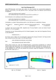
• Added Freebody tool to all facets of Freebody display post-processing.
PostProcessing Toolbox <strong>10.3</strong>-7<br />
The Freebody tool is the gateway to using freebody diagrams <strong>for</strong> post-processing. The freebody display can be per<strong>for</strong>med<br />
at any time, whether you are showing a de<strong>for</strong>med and contour plot, or a simple unde<strong>for</strong>med plot. The<br />
“type” of freebody display, the output set and contributions used in the calculations, and many view options <strong>for</strong><br />
freebody entities are all controlled via this tool. In order to use the Freebody tool fully, the “Grid Point Force” and<br />
“Grid Point Moment” results must have been recovered from Nastran. This is done in FEMAP by selecting the<br />
“Force Balance” option in the Nastran Output Requests dialog box found in the Analysis Set Manager. See Section<br />
4.10.1.5, "Output Requests" <strong>for</strong> more in<strong>for</strong>mation.<br />
Visibility icon button A Freebody entity must be created be<strong>for</strong>e any additional<br />
options may be specified. To do this, use the<br />
Freebody Manager icon button<br />
Freebody Manager, which is accessed by pressing<br />
the Add Freebody icon button next to the drop-down<br />
list next to Freebody in the Freebody Properties section.<br />
Multiple Freebody entities may be created.<br />
Once Freebody entities have been created, each may<br />
be made visible or hidden individually in all views<br />
using the Is Visible check box in the Freebody Properties<br />
section or the check boxes in the Freebody tab<br />
of the Visibility dialog box (see Section 6.1.4, "View,<br />
Visibility..."). The “...” icon button next to Display<br />
Freebodies will give direct access to the Visibility<br />
dialog box with the Freebody tab selected.<br />
Options - Freebody tool<br />
The Freebody tool is divided into 3 sections. The top<br />
of the Freebody tool contains 3 options which affect<br />
all Freebody entities in a View. The options in the<br />
Freebody Properties section changes based on<br />
which Freebody entity is selected with the Freebody<br />
drop-down list. Options in View Properties section<br />
change depending on which View is currently active<br />
in the model.<br />
The three options at the top of the Freebody tool are<br />
used to control the overall visibility of all Freebody<br />
entities (Display Freebodies), which Output Set will<br />
be used to create the freebody display, and if data<br />
should be summed at nodes (Sum Data on Nodes).<br />
The arrow icons can be used to go to the Next or<br />
Previous output set or the Select Output Set icon button<br />
can be used to access the Select Output Set dialog<br />
box. See Select Output Set and Select Output<br />
Vector dialog boxes section <strong>for</strong> more in<strong>for</strong>mation.<br />
When Sum Data On Nodes is on, the grid point <strong>for</strong>ce<br />
and moment data from all element corners attached<br />
to that node will be summed at each node. When off,<br />
the individual grid point <strong>for</strong>ces and moments will be<br />
displayed at each element corner along with the element<br />
ID next to the value in parentheses.<br />
Freebody Properties<br />
Freebody - This drop-down is used to select which<br />
options are currently available <strong>for</strong> use in the Freebody<br />
Properties section. To create a new Freebody<br />
entity or edit an existing one, click the Add Freebody icon button to access the Freebody Manager.
<strong>10.3</strong>-8<br />
Finite Element Modeling<br />
• Freebody Manager - Used to create, edit, renumber, copy, and delete Freebody entities.<br />
Title Filter<br />
Clear Title Filter<br />
<strong>New</strong> Freebody - When clicked, the <strong>New</strong> Freebody dialog box will appear.<br />
In this dialog box, specify an ID and Title (optional) along with some “top-level” options <strong>for</strong> the new Freebody<br />
entity, such as Display Mode , Vector Display Freebody Contributions, and Load Components in Total Summation.<br />
These options will be described later in this section<br />
Update Title - Highlight a Freebody entity in Available Freebodies list, then click this button to enter a new Title.<br />
Renumber - Highlight a Freebody entity in Available Freebodies list, then click this button to change the ID.<br />
Delete - Highlight a Freebody entity in Available Freebodies list, then click this button to delete it from the model.<br />
Delete All - Deletes all Freebody entities in the model.<br />
Copy - Highlight a Freebody entity in Available Freebodies list, then click this button to make a copy.<br />
None Active - When clicked, there is no longer an “Active” Freebody entity.
PostProcessing Toolbox <strong>10.3</strong>-9<br />
Default Settings - When clicked, the following options are set:<br />
Display Mode: “Freebody Only”<br />
Vector Display: “Nodal Forces” displayed as Components, “Nodal Moments” Off<br />
Freebody Contributions: “Applied”, “Reaction”, “MultiPoint Reaction”, and “Peripheral Elements” On, “Freebody<br />
Elements” and “Nodal Summation” Off.<br />
More - Click this button to create another new Freebody entity.<br />
Freebody Tools - This section contains four icon buttons used <strong>for</strong> sending the data used in the calculations to create<br />
the freebody display to the Messages window or the Data Table.<br />
Freebody to Messages<br />
Summation to Data Table<br />
Freebody to Data Table<br />
Summation to Messages<br />
• List Freebody to Messages Window - Lists all contributions used to create the display of the Freebody entity<br />
currently selected in the Freebody tool to the Messages window. ID is the node ID where the Nodal Force and<br />
Nodal Moment vectors are being calculated and Source is the Element ID which is providing the <strong>for</strong>ce and<br />
moment contributions.
<strong>10.3</strong>-10<br />
Finite Element Modeling<br />
• List Freebody to Data Table - Reports all contributions used to create the display of the Freebody entity currently<br />
selected in the Freebody tool to the Data Table. The ID is the node ID where the Nodal Force and Nodal<br />
Moment vectors are being calculated and Source is the Element ID which is providing the <strong>for</strong>ce and moment<br />
contributions<br />
• List Freebody Summation to Messages Window (Display Mode set to “Interface Load” only) - Lists all contributions<br />
used to create the display of the Total Summation Vector <strong>for</strong> the Freebody entity currently selected in<br />
the Freebody tool to the Messages window. The “Header” above the listing contains in<strong>for</strong>mation about the<br />
“Components included in summation”, “Contributions included in the summation”, and “location” of the summation.<br />
The (F) and (P) designators in the listings indicate contributions from Freebody Elements (F) and contributions<br />
from Peripheral Elements (P). The d1, d2, and d3 fields represent the distance from the X, Y, and Z<br />
location of the node (Node ID) to the location where the summation is taking place
PostProcessing Toolbox <strong>10.3</strong>-11<br />
• List Freebody Summation to Data Table (Display Mode set to “Interface Load” only) - Reports all the same<br />
in<strong>for</strong>mation as List Freebody Summation to Messages Window, but sends it to the Data Table. One difference is<br />
that the “Header” in<strong>for</strong>mation is still sent to the Messages window, as there is no logical place to report this<br />
in<strong>for</strong>mation in the Data Table.<br />
Is Visible - When On, the Freebody entity currently in the Freebody drop-down will be visible in the graphics window<br />
in all views. Display of Freebody entities may also be controlled via the Freebody tab of the Visibility dialog<br />
box.<br />
Coordinate System - Drop-down list specifies which coordinate system should be used to display the freebody<br />
vectors. You can create a new coordinate system by using the <strong>New</strong> Coord Sys icon button.<br />
Display Mode - Each Freebody entity can be displayed in two different modes, Freebody or Interface Load.<br />
• Freebody - Only Freebody Elements may be selected in the Entities section and only the vectors in the Nodal<br />
Vector(s) section can be displayed and controlled.<br />
• Interface Load - Both Freebody Nodes and Freebody Elements must be selected in the Entities section and<br />
vectors in both the Nodal Vector(s) and the Total Summation Vector sections can be displayed and controlled.<br />
Additionally, a Location must be selected when using this option.<br />
Note:<br />
Only entities which can be displayed and controlled by the selected Display Type will be available in<br />
the Freebody Entity Colors section, while setting the View Properties <strong>for</strong> all the different freebody<br />
vector types and nodes markers is available at all times.<br />
Entities - Allows you to specify which Freebody Elements (Display Mode = “Freebody”) or Freebody Nodes and<br />
Freebody Elements (Display Mode = “Interface Load”) are used by a Freebody entity. Based on the Entity Selection<br />
Mode, elements and nodes may be selected <strong>for</strong> the Freebody entity directly or by using a pre-defined group.<br />
• Entity Selection Mode - When set to Entity Select, elements and nodes are selected, highlighted in the graphics<br />
widow, or deleted from the Freebody entity using the icon buttons below. An additional icon button exists <strong>for</strong><br />
placing the summation location at the center of the selected nodes.<br />
Display Mode = Freebody<br />
Display Mode = Interface Load<br />
Select Elements<br />
Delete Elements<br />
<strong>for</strong> Freebody<br />
from Freebody<br />
Highlight Elements in Freebody<br />
Select Nodes<br />
<strong>for</strong> Interface Load<br />
Highlight Selected Nodes<br />
<strong>for</strong> Interface Load<br />
Delete Elements<br />
from Freebody<br />
Place Summation<br />
point at center of<br />
Selected Nodes<br />
When set to Group Select, elements and nodes are determined by selecting a group from the Group drop-down list.<br />
If Group is set to “-1..Active”, then the elements will be retrieved from the Active group in the model. The Group<br />
Manager dialog box may also be accessed by the icon button next to the Group drop-down (see Section 6.4.3.1,<br />
"Group, Create/Manage..." <strong>for</strong> more in<strong>for</strong>mation).<br />
Total Summation Vector (Display Mode set to “Interface Load” only) - Allows you to specify the Location of the<br />
Total Force Vector and Total Moment Vector, along with how these vectors are displayed and what components will<br />
be summed to create these vectors.<br />
• Location - Allows you to specify the location of summation <strong>for</strong> the Total Summation Vector. Click the icon button<br />
next to location to pick a location from the graphics window. Additionally, the individual coordinates may<br />
be entered or edited below the Location, when expanded.
<strong>10.3</strong>-12<br />
Finite Element Modeling<br />
When nodes are selected in the Entities<br />
section, the user will be prompted to<br />
answer the following question:<br />
Auto-locate total summation vector at<br />
center of freebody nodes (“X-coordinate”,<br />
“Y-coordinate”, “Z-coordinate”<br />
in coordinate system “ID of Coordinate<br />
System specified in Freebody<br />
Properties”)?<br />
If you click Yes, the Location will be<br />
specified at the center of the selected<br />
nodes. If you click No, the Location<br />
will be at (0.0, 0.0, 0.0) or the Location<br />
last used by the Freebody entity currently<br />
in the Freebody tool.<br />
• Force Vector Display - This option controls how the “Force vector” (single arrow head) of the Total Summation<br />
Vector will be displayed. When set to “Off”, the <strong>for</strong>ce vector will be not be displayed. When set to “Display<br />
Components”, the <strong>for</strong>ce vector will be displayed in X, Y, and/or Z Components (individual components may be<br />
toggled on/off using the FX, FY, and FZ check boxes <strong>for</strong> Displayed Forces). When set to “Display Resultant”,<br />
the <strong>for</strong>ce vector will be displayed as a single resultant vector based on the components currently “on” in Displayed<br />
Forces.<br />
• Moment Vector Display - This option controls how the “Moment vector” (double arrow head) of the Total<br />
Summation Vector will be displayed. When set to “Off”, the moment vector will be not be displayed. When set<br />
to “Display Components”, the moment vector will be displayed in X, Y, and/or Z Components (individual components<br />
may be toggled on/off using the MX, MY, and MZ check boxes <strong>for</strong> Displayed Moments). When set to<br />
“Display Resultant”, the moment vector will be displayed as a single resultant vector based on the components<br />
currently “on” in Displayed Moments.<br />
• Summed Components - This option controls which Force and Moment components will be used to calculate<br />
the Total Summation Vector. Turning individual Force components on/off is also very likely to affect the<br />
Moment values, so keep that in mind.<br />
Following figures show the Total Summation Vector. Freebody Node Markers are “On”, Node Vector(s) not displayed,<br />
Element Transparency set to 75%, and Element Shrink View Option is “On”.<br />
Display Mode = Interface Load<br />
Total Summation Vector Force and<br />
Moment set to “Display Resultant”<br />
Display Mode = Interface Load<br />
Total Summation Vector Force set to “Off”<br />
and Moment set to “Display Components”<br />
Nodal Vector(s) - Allows you to control how the Force and Moment vectors are displayed at each node (Sum Data<br />
on Nodes in View Properties section “On”) or each “element corner” (Sum Data on Nodes “Off”).<br />
• Force Vector Display - This option controls how the “Force vectors” (single arrow head) are displayed. When<br />
set to “Off”, the <strong>for</strong>ce vectors will be not be displayed. When set to “Display Components”, the <strong>for</strong>ce vector at<br />
each node/element corner will be displayed in X, Y, and/or Z Components (individual components may be tog-
PostProcessing Toolbox <strong>10.3</strong>-13<br />
gled on/off using the FX, FY, and FZ check boxes <strong>for</strong> Displayed Forces). When set to “Display Resultant”, the<br />
<strong>for</strong>ce vector at each node/element corner will be displayed as a single resultant vector based on the components<br />
currently “on” in Displayed Forces.<br />
• Moment Vector Display - This option controls how the “Moment vectors” (double arrow head) are displayed.<br />
When set to “Off”, the moment vectors will be not be displayed. When set to “Display Components”, the<br />
moment vector at each node/element corner will be displayed in X, Y, and/or Z Components (individual components<br />
may be toggled on/off using the MX, MY, and MZ check boxes <strong>for</strong> Displayed Moments). When set to “Display<br />
Resultant”, the moment vector at each node/element corner will be displayed as a single resultant vector<br />
based on the components currently “on” in Displayed Moments..<br />
When Sum Data on Nodes is “On”, the Nodal Vector(s) will be at each node:<br />
Display Mode = Freebody<br />
Nodal Vector(s): Force Set to “Display<br />
Components”, Moment set to “Off”<br />
Display Mode = Freebody<br />
Nodal Vector(s): Force Set to “Off”,<br />
Moment set to “Display Resultant”<br />
When Sum Data on Nodes is “Off”, the Nodal Vector(s) at each element corner will include the Element ID<br />
Forces shown using “Display Components” at “element corners”<br />
Moments shown using “Display Components” at “element corners”<br />
Freebody Contributions From - Allows you to control the calculation of the Freebody entity by choosing which<br />
contributions should be included. Available contributions are from Applied Loads, from Reaction Forces and<br />
Moments at single point constraints and/or constraint equations, from the selected elements (Freebody Elements),<br />
and from the elements surrounding the Freebody Elements (Peripheral Elements). Toggling various options on/off<br />
can drastically alter the values and appearance of a Freebody entity, so be sure to have the proper contributions<br />
included <strong>for</strong> your particular needs.<br />
• Applied - When On, includes contributions from all loads applied to the model used to produce the results in<br />
the selected Output Set.<br />
• Reaction - When On, includes contributions from all reaction <strong>for</strong>ces and moments at single point constraints in<br />
the model used to produce the results in the selected Output Set.<br />
• MultiPoint Reaction - When On, includes contributions from all reaction <strong>for</strong>ces and moments from constraint<br />
equations, rigid elements, and interpolation elements in the model used to produce the results in the selected<br />
Output Set.
<strong>10.3</strong>-14<br />
Finite Element Modeling<br />
• Peripheral Elements - When On, includes grid point <strong>for</strong>ce and moment contributions from the selected Output<br />
Set <strong>for</strong> the elements surrounding the Freebody Elements selected in Entities section.<br />
• Freebody Elements - When On, includes grid point <strong>for</strong>ce and moment contributions from the selected Output<br />
Set <strong>for</strong> the elements selected in Entities section.<br />
• Nodal Summation - When On, includes <strong>for</strong>ce and moment contributions from nodal summation. Typically,<br />
these are very small numbers, unless there is a “non-balanced” <strong>for</strong>ce or moment in the model.<br />
Contributions = Applied, Reaction, and Peripheral Elements<br />
Freebody Elements = 75% Transparent in figure<br />
Sum Data on Nodes = On, Freebody Node Markers = On<br />
Contributions = Applied, Reaction, and Freebody Elements<br />
Peripheral Elements = 75% Transparent in figure<br />
Sum Data on Nodes = Off, Freebody Node Markers = On<br />
Freebody Entity Colors - Allows you to specify colors <strong>for</strong> Node Marker(s), Total Force Vector, Total Moment<br />
Vector, Nodal Force Vector(s), and/or Nodal Moment Vector(s) <strong>for</strong> each Freebody entity. Click the icon button to<br />
select a color from the Color Palette. These colors will only be used when the “Color Mode” <strong>for</strong> any of these items<br />
is set to “Freebody Entity Color” in the View Properties section of the Freebody tool or via the Freebody... options<br />
in the View Options dialog box, PostProcessing category (See Section 8.3.25, "Freebody options").<br />
View Properties<br />
The View Properties control the visibility, style, color, and labeling <strong>for</strong> Freebody display. Each view in the model<br />
can have different options set in the section. When a different view is activated, the values from that view will fill<br />
the View Properties section.<br />
Show Node Markers - controls the visibility, symbol size, and color of the “node markers” <strong>for</strong> Freebody entities.<br />
Having the node markers visible is a good way to visually inspect the nodes or element corners being used in the<br />
freebody calculations. The Symbol Size can be entered directly or increased/decreased using the “slider bar”. When<br />
Color Mode is set to “Freebody Entity Color”, the node markers will use the color specified <strong>for</strong> Freebody Node<br />
Marker(s) in the Freebody Properties section.<br />
Vector Options - controls the Label Mode, Length, and Label Format of the Freebody vectors. Label Mode allows<br />
you to display No Labels, the Value of each freebody vector, or the value using exponents. For Label Format, the<br />
number of digits may be entered directly or increased/decreased using the “slider bar”. This will chance the number<br />
of significant digits being displayed. When Label Format is set to “0”, this is an “automatic mode” and FEMAP<br />
will determine the number of significant digits to display.<br />
When Adjust Length is “off”, the length of each freebody vector “type” is controlled by a combination of the<br />
entered Length value and the Factor value entered <strong>for</strong> the Freebody Total Force, Freebody Total Moment, Freebody<br />
Nodal Force, and Freebody Nodal Moment view options.<br />
When Adjust Length is “on”, the length of the freebody vectors will be adjusted based on the vector’s value (i.e.,<br />
larger values = longer vectors). The Units/Length value is an additional parameter used to control the length of the<br />
vectors when in this mode. Essentially, the Units/Length value is used in the following manner:<br />
If Units/Length value is 250, then a freebody vector value of 500 would be shown using a length of “2*Factor” on<br />
the screen. For the same freebody vector value of 500, entering a Units/Length value of 100 would display the vector<br />
using a length of “5*Factor” on the screen.<br />
Min Vector Magnitude - allows you to set a tolerance below which the vectors are not displayed. Using the default<br />
value of 1.0E-8, this option will basically remove vectors from the display that are not zero just due to numerical<br />
round-off. The value can also be used as a cut-off value, so if it is set to 10, only vector values above 10 will be displayed.
Geometry <strong>10.3</strong>-15<br />
Total Force Vector/Total Moment Vector - controls the Vector Style, Color Mode, and Factor <strong>for</strong> the Total Summation<br />
Force and Moment vectors. The Total Summation vectors are only visible when the Display Mode of a<br />
Freebody entity is set to “Interface Load”.<br />
When Vector Style is set to Arrow or Center Arrow, the vectors will be displayed as lines. When set to Solid Arrow<br />
or Center Solid Arrow, the vectors will be “thicker, filled-in solids”. Factor is an additional scale factor which can<br />
be entered to change the size of the selected vector type.<br />
When Color Mode is set to Freebody Entity Color, the “Freebody Entity Colors” specified <strong>for</strong> each Freebody entity<br />
in the Freebody tool is used. This allows multiple Freebody entities to be displayed at one time using unique colors<br />
<strong>for</strong> clarity. RGB Color uses Red to display the X component, Green <strong>for</strong> the Y component, and Blue <strong>for</strong> the Z component<br />
of each vector.<br />
Nodal Force Vector/Nodal Moment Vector - offers the same options as Freebody Total Force/Freebody Total<br />
Moment, but these options control the Nodal Vector(s). One difference is in Color Mode, where an additional<br />
option, Source Color exists. When set to Source Color, this selected vector type uses the color of the “source” elements,<br />
the color of the load <strong>for</strong> Applied loads, and/or the color of the constraint <strong>for</strong> Reaction <strong>for</strong>ces and moments.<br />
When the Sum Data on Nodes option is “on” and Source Color is selected, the View Color will be used.<br />
Geometry<br />
Meshing<br />
• Enhanced Geometry, Solid, Embed to allow embedding of multiple solids into the base solid all at once.<br />
• Enhanced “Suppress Short Edges” option in Mesh, Mesh Sizing, Size on Surface and Mesh, Mesh Sizing, Size<br />
on Solid to be a percentage of Mesh Size instead of a percentage of “average curve length” on selected geometry.<br />
• Added Mesh, Geometry Preparation command<br />
This command uses a set of parameters to find situations in geometry which typically result in poor element quality,<br />
then uses a combination of automatic curve/surface splitting, creation of Combined Curves/Boundary Surfaces,<br />
and feature suppression to likely improve mesh quality. In addition, this command will “prepare” some parts to a<br />
degree which will allow FEMAP to successfully mesh the part.<br />
Note:<br />
If FEMAP is successful when meshing a solid with acceptable mesh quality <strong>for</strong> your application, then<br />
using “Mesh, Geometry Preparation” is probably not necessary. Also, please be aware when using this<br />
process, it is quite common <strong>for</strong> certain small features to be ignored or removed completely.<br />
In most cases, this automatic process will be all that is need to produce a good quality mesh. However, even if it<br />
cannot fully automatically produce an acceptable mesh, it will still provide a good starting point <strong>for</strong> using the other<br />
interactive geometry cleanup tools, and greatly reduce the amount of work required.<br />
Note:<br />
It is recommended to use the “Mesh, Geometry Preparation” command BEFORE manually creating<br />
additional Combined Curves /Boundary Surfaces <strong>for</strong> meshing purposes.<br />
Surfaces and Curves which have loads or boundary conditions applied will be ignored.<br />
By default, the command goes through two steps, Prepare Geometry and Mesh Sizing. You can choose to skip<br />
either step by simply un-checking the box next to Prepare Geometry or Mesh Sizing. The value <strong>for</strong> size shown <strong>for</strong>
<strong>10.3</strong>-16<br />
Finite Element Modeling<br />
both Prepare Geometry and Mesh Sizing is the “Default Mesh Size” calculated by FEMAP (uses the same algorithm<br />
as "Mesh, Geometry, Solids").<br />
Prepare Geometry<br />
The value <strong>for</strong> Prepare Geometry is simply used as a baseline value <strong>for</strong> the various Prepare Options. There<strong>for</strong>e, it is<br />
typically a good idea to change the Prepare Geometry value instead of the individual Prepare Options values.<br />
Prepare Options button<br />
Opens the Geometry Preparation Options dialog box. In general, the "Prepare Geometry" process has been developed<br />
to function most effectively using the default values in the "Maximum Sizes and Angles" section and all of<br />
the "Preparation Options" set to "on", except "Combine Small Surfaces". These values should only be changed<br />
and/or options turned off if you run into a problem.<br />
Surfaces, Curves and Points to Ignore - allows you to choose a group containing Surfaces, Curves, and/or Points<br />
to exclude from the "Prepare Geometry" process.<br />
Maximum Sizes and Angles - allows you to specify “percentage of prepare size” and angle tolerances to help control<br />
the “Prepare Geometry” process. There are 5 values to set:<br />
• Narrow Region Factor (default = 10%) - If distance between two locations on a region of a surface is less than<br />
n% of "Prepare Size", the surface will be split. The locations where distance is checked are automatically determined<br />
by faceting the curves based on a percentage of "Prepare Size" (the faceting percentage cannot be<br />
changed by the user).<br />
For example, this simple part has a “narrow region”. Without going through the “Prepare Geometry” process, the<br />
worst elements in the resulting mesh have a “Tet Collapse Ratio” of 16.437 and a “Jacobian” of 0.8386167..
Meshing <strong>10.3</strong>-17<br />
Zoomed-in view of “narrow region” at the corner of the part:<br />
After the “Prepare Geometry” process using the defaults, the “narrow region” has been split from the original surface,<br />
then combined with surfaces from the “base”. Also, two short curves at the split locations have been suppressed.<br />
Finally, 2 Combined Curves have been created to allow larger elements in an area that used to be restricted<br />
by the “narrow region” Worst elements now have “Tet Collapse Ratio” of 5.67 and “Jacobian” of 0.694<br />
.<br />
Close-up of “narrow region” split<br />
“Split Curve” is suppressed<br />
Close-up of Combined Curve and<br />
Boundary Surfaces at Corner
<strong>10.3</strong>-18<br />
Finite Element Modeling<br />
A surface which has a “narrow region” that connects two other larger regions is also a good candidate <strong>for</strong> splitting,<br />
then combination to other surfaces. A surface may be split multiple times if needed to isolate the “narrow region”.<br />
Be<strong>for</strong>e “Prepare Geometry” process<br />
When meshed, Worst Tet Collapse = 15.72<br />
Worst Jacobian = 0.793<br />
After “Prepare Geometry” process<br />
When meshed, Worst Tet Collapse = 4.642<br />
Worst Jacobian = 0.458<br />
• Curve Suppression Factor (default = 5%)- If curve is less than n% of "Prepare Size", it will be suppressed.<br />
Also, if all curves on a surface are less than n% of "Prepare Size", the surface will also be suppressed and the<br />
surface "collapsed to a single point".<br />
• Narrow Angle (default = 15 degrees) - If a surface has a narrow region, but the tangent vectors of the bounding<br />
curves at the locations where the "narrowness" occurs are not within this value, then the split will not occur.<br />
See description of "Detect Close Points" in the "Preparation Options" section <strong>for</strong> some exceptions.<br />
• Feature Edge Angle (default = 15 degrees) - If angle of a feature is more than this value, then the "Prepare<br />
Geometry" process will look <strong>for</strong> other surfaces which are not above this threshold to combine with surfaces<br />
which will benefit from being combined. If no other suitable surface can be located, then surfaces which are<br />
over this value may still be combined when needed.<br />
• Combined Curve Angle (default = 30 degrees) - If angle if larger than this value, curves will not be combined.<br />
Unlike combining curves via the Meshing Toolbox, which has the option to create boundary surfaces while creating<br />
combined curves, this command only deals with combined curves. This is because the surfaces to combine<br />
have already been determined earlier in the "Prepare Geometry" process.<br />
Preparation Options - allows you to toggle 6 different options of the “Prepare Geometry” process on/off.<br />
• Geometry Cleanup - When on, applies a subset of options found in the "Geometry, Solid, Cleanup" command to<br />
attempt cleanup of any numerical issues which may exist in the geometry. Many times, these types of issues<br />
arise during translation of the geometry.<br />
• Detect Close Points - When on, detects when a point between two bounding curves of a surface is very close to<br />
a location on a third bounding curve on the surface (i.e., "knife edge"), then splits the surface at these locations<br />
and suppresses the "split curve". Using the default values <strong>for</strong> "Narrow Region Factor" and "Narrow Angle",<br />
this case would be ignored.<br />
For example, the angles of the curves at the “narrow region” location on the part below are not within the “Narrow<br />
Angle” tolerance value. If “Detect Close Points” is “off”, this portion of the geometry will not be “prepared”..<br />
“Detect Close Points” Set to “Off”<br />
Nothing split or suppressed<br />
“Detect Close Points” Set to “On”<br />
Surface split and “split line” suppressed
Meshing <strong>10.3</strong>-19<br />
• Cut Slivers - When on, will review all surfaces considered "slivers" and determine if they should be "cut" again<br />
to allow <strong>for</strong> more effective combining with adjacent surfaces.<br />
• Process Blends - When on, attempts to combine small fillet surfaces in a "fillet chain" to larger surfaces in the<br />
"fillet chain" to create Boundary Surfaces in hopes of creating a better surface mesh.<br />
For example, this simple part has a “fillet chain” with a small surface near larger surfaces:<br />
Be<strong>for</strong>e “Prepare Geometry” process<br />
After “Prepare Geometry” process<br />
Smaller fillet surface combined to<br />
larger surface in “Fillet chain”<br />
• Combine Small Surfaces - In many cases, suppressing very small surfaces entirely is a better option, there<strong>for</strong>e<br />
this option is off by default. When on, attempts to combine very small surfaces to surrounding surfaces instead<br />
of suppressing them.<br />
• Delete Previous Mesh - When on, deletes any existing surface and/or solid mesh currently on the solid which<br />
was selected <strong>for</strong> the "Prepare Geometry" process.<br />
Mesh Sizing and Sizing Options button<br />
The value <strong>for</strong> Mesh Sizing and the options found when the Sizing Options button is pressed are mostly the same as<br />
options found in the "Mesh, Mesh Control, Size on Solid" command (see Section 5.1.2.4, “Mesh, Mesh Control,<br />
Size on Surface...”). The one exception is that Max Size of Small Feature is entered as a percentage of the Mesh Sizing<br />
value entered in the Geometry Preparation and Sizing dialog box instead of being entered as an actual value.<br />
Interior Growth Factor<br />
Same as Growth Factor in the “Surfaced Interior Mesh Growth” section of the "Mesh, Mesh Control, Surface" and<br />
"Mesh, Mesh Control, Solid" (see Section 5.1.2.4, “Mesh, Mesh Control, Size on Surface...”). Value (1.0 by<br />
default) may be changed using the slider bar or by manually typing in a value (must be between 1.0 and 10.0).<br />
Sync Prepare and Size<br />
When on (default), the values <strong>for</strong> Prepare Geometry and Mesh Sizing will change at the same time to the same<br />
value when the slider is moved left or right or the value is entered manually into either field.<br />
Suppress Internal Voids<br />
When on (default), suppress any volumes which are completely contained within the solid (<strong>for</strong> example, a cube<br />
with an internal sphere).<br />
Note:<br />
There is no "limiting size" on an internal void, so if you have a mostly hollow structure (i.e., pressure<br />
vessel or fully enclosed tank), and this option is on, the entire “internal void” will be suppressed.<br />
Remove Combined Curves/Surfaces<br />
When on (default after “Mesh, Geometry Preparation” command has been used once), will remove Combined<br />
Curves/Boundary Surfaces on the geometry currently selected be<strong>for</strong>e starting the "Prepare Geometry" process.<br />
Sizing Type<br />
Same as "Sizing Type" of the "Mesh, Mesh Control, Surface" and "Mesh, Mesh Control, Solid" commands (see<br />
Section 5.1.2.4, “Mesh, Mesh Control, Size on Surface...”). "2..Parametric/Equal Length" is the default.<br />
Remove Previous button<br />
Removes all Combined Curves/Boundary Surfaces, along with any "surface splits" created by the most recent use<br />
of the "Mesh, Geometry Preparation" command on the selected geometry. Exits the command after completion.
<strong>10.3</strong>-20<br />
Finite Element Modeling<br />
• Added Improve Collapsed Tets option to the Solid Automeshing Options dialog box of the Mesh, Geometry,<br />
Solid command, which is accessed by click the Options button.<br />
When this option is “on” (default), the mesher will locate elements with a “Tet Collapse Ratio” higher than the<br />
specified value (default is 100), then attempt to improve the mesh quality by moving “internal nodes” to new locations.<br />
Once the nodes have been moved, the new “triangular seed mesh” is sent through the tet mesher again.<br />
• Renamed the Length Based Sizing option in the Mesh, Mesh Control, Size on Surface and Mesh, Mesh Control,<br />
Size on Solid commands to Sizing Type and added the “2..Parametric/Equal Length” option, which is also now<br />
the default.<br />
When this option is set to “0..Parametric”, all sizing along curves is done in the parametric space of the curves. In<br />
many cases this is desirable resulting in a finer mesh in areas of high curvature. In some cases however - with<br />
unstitched geometry, or geometry that has curves with unusual parameterization - “1..Equal Length” spacing along<br />
the curves will yield much better results. Especially when dealing with unstitched geometry, “equal length” spacing<br />
will produce meshes with matching nodal locations far more reliably than “parametric” spacing. The default is<br />
"2..Parametric/Equal Length", which sizes all curves using the "Parametric" option, then determines an "average<br />
distance" between each of the "mesh locations" on each curve. If the distance between any of the mesh locations is<br />
more than 1% different than the "average distance", then that curve is resized using "Equal Length" sizing.<br />
• Improved the Surface Interior Mesh Growth option in the Mesh, Mesh Control, Size on Surface and Mesh, Mesh<br />
Control, Size on Solid commands to allow mapped meshing on surface where it was applied. Previously,<br />
mapped meshing was not available on these surfaces.<br />
• Improved Mesh, Mesh Control, Custom Size Along Curve command to remove the limitation on number of custom<br />
points which can be assigned.<br />
Elements<br />
Materials<br />
• Updated the Spring/Damper element to use the Type, either CBUSH or Other (NASTRAN CROD/CVISC), specified<br />
on the Property referenced by the element to determine if a CBUSH or a combination of CROD and/or<br />
CVISC elements will be exported to Nastran. Formally, this was done by setting the element <strong>for</strong>mulation. Also,<br />
the Define Spring/Damper Element dialog box will now change to show the appropriate inputs based on the<br />
Type of the referenced Property. Finally, CBUSH elements will now use a circular symbol <strong>for</strong> display, while<br />
Other (NASTRAN CROD/CVISC) elements will use a rectangular symbol.<br />
• Added Mullins Effect (MATHEM) and Viscoelastic Effect (MATHEV) support <strong>for</strong> NX Nastran Hyperelastic<br />
materials fpr SOL 601/701 in Other Types. The additional options are accessed using the Next button when<br />
defining Mooney-Rivlin, Hyperfoam, Ogden, Arruda-Boyce, or Sussman-Bathe types.<br />
• Added Viscoelasitc Material (MATVE) in Other Types <strong>for</strong> NX Nastran SOL 601.<br />
• Added NITONAL material type in Other Types <strong>for</strong> NEi Nastran..<br />
Properties<br />
• Added Mean Dilatational Formulation option to Plane Strain Property. This option is <strong>for</strong> NX Nastran only and<br />
is <strong>for</strong> properties which do not reference a hyperelastic material <strong>for</strong> Plane Strain or Plane Stress Elements. The<br />
<strong>for</strong>mulation of the elements also must be set to “1..CPLSTN3, CPLSTN4, CPLSTN6, CPLSTN8” (Plane<br />
Strain) or “2..CPLSTS3, CPLSTS4, CPLSTS6, CPLSTS8” (Plane Stress) in order to export this property type.<br />
The “Mean Dilatational Formulation” switch on the property may be used <strong>for</strong> nearly incompressible materials,<br />
but is ignored <strong>for</strong> SOL 601. Also, Nonstructural mass/are is ignored <strong>for</strong> SOL 601.<br />
• Added Type in Spring/Damper Property to define if the elements referencing this Property are CBUSH elements<br />
or a combination of CROD and/or CVISC elements when exporting to Nastran.<br />
• Added support <strong>for</strong> NEi Nastran Failure Theories, Max Stress (STRESS), NASA LaRC (LAERC02), Puck PCP<br />
(PUCK), and Multicontinium (MCT), on Laminate Property.
Aeroelasticity - <strong>New</strong> <strong>for</strong> <strong>10.3</strong>! <strong>10.3</strong>-21<br />
Aeroelasticity - <strong>New</strong> <strong>for</strong> <strong>10.3</strong>!<br />
The commands under the Model, Aeroelasticity menu are used to create entities required to per<strong>for</strong>m Static<br />
Aeroelastic analysis (SOL 144) and Aerodynamic Flutter analysis (SOL 145) with Nastran solvers. An underlying<br />
finite element model is also needed to properly run an aeroelastic analysis. Typically, this underlaying “structural<br />
model” consists of only beam and/or shell elements.<br />
There are 4 different types of aeroelastic entities supported <strong>for</strong> Nastran:<br />
• Aero Panel/Body<br />
• Aero Property<br />
• Aero Splines<br />
• Aero Control Surfaces<br />
The various “Aero entities” interact with one another in several ways. Every Aero Panel/Body is required to have<br />
an appropriate Aero Property assigned. Several Aero Panels/Bodies may reference the same Aero Property.<br />
Next, each Aero Spline must reference an Aero Panel/Body and a group of “structural” nodes in the model. The<br />
Aero Spline entities connect the “aeroelastic model” to the underlying “structural model”. Any number of “aerodynamic<br />
boxes” (Aero Mesh) may be selected from the referenced Aero Panel/Body.<br />
Finally, each Aero Control Surface needs to reference at least one “aerodynamic box” (Aero Mesh) on an Aero<br />
Panel/Body set to “Aero Panel”.<br />
Once all the Aero entities have been defined, additional options <strong>for</strong> Static Aeroelasticity and Aerodynamic Flutter<br />
will need to be set using the Analysis Set Manager.<br />
Model, Aeroelasticity, Panel/Body...<br />
...creates an Aero Panel or Aero Body (Slender Body and/or Interference Body). The dialog box changes depending<br />
on what is specified <strong>for</strong> Aero Body Type. When Aero Body Type is set to “0..Aero Panel (CAERO1)”, then FEMAP<br />
is making an “Aero Panel”, which will be written to Nastran as a CAERO1 entry. When Aero Body Type is set to<br />
“1..Aero Body (CAERO2)”, then FEMAP is making a “Slender/Interference Body”, which will be written to Nastran<br />
as a CAERO2 entry. Each Aero Body Type contains different inputs, will be discussed in greater detail later.<br />
The ID, Title, Color, Layer, and Property fields are common to both Aero Body Types, as well as the Orientation<br />
CSys and IGID fields in the Options section.<br />
Note:<br />
The ID value <strong>for</strong> Aero Panel will increment by 1000 automatically. This is due to to the fact that<br />
each Aero Panel/Body has a Mesh Control section which defines the “Aero Mesh” (Number Chord<br />
* Number Span <strong>for</strong> an “Aero Panel”, Number of Body Elements <strong>for</strong> “Aero Slender Body”) and each<br />
“Aero Element” must have a unique ID. FEMAP numbers the “Aero Mesh” using the Aero Panel/<br />
Body ID as a prefix. For example, an “Aero Panel” with ID of 2000 has Number Chord set to 10<br />
and Number Span set to 5 <strong>for</strong> a total of 50 “Aero Elements”. They are numbered 2000 to 2049 <strong>for</strong><br />
this Aero Panel.<br />
Select an existing Aero Property from the Property drop-down. The Type on the Areo Property must correspond to<br />
the Aero Body Type on Aero Panel/Body (i.e., Type must be “Aero Body (PAERO2)” on the Aero Property used by<br />
an Aero Panel/Body with Aero Body Type set to “1..Aero Body (CAERO2)”). If an Aero Property does not currently<br />
exist, click the Create Aero Property icon button to create one “on-the fly”.<br />
Orientation CSys is used to orient the locations of Point 1 and Point 4 (Aero Panel Only) and is written to the CP<br />
field of the CAEROi entry, while IGID designates the “Interference Group ID” and writes out the IGID field to<br />
CAEROi entry (aerodynamic elements with different IGIDs are uncoupled).<br />
Note:<br />
To change the IGID value on multiple Aero Panel/Body entities all at once, use the Modify, Update<br />
Other, Aero Interference Group command.
<strong>10.3</strong>-22<br />
Finite Element Modeling<br />
Aero Body Type = “0..Aero Panel (CAERO1)”<br />
This Aero Body Type will create an “Aero Panel”. The values represent two “leading edge” locations and the length<br />
of two “side chords”. The number of divisions <strong>for</strong> “chord” and “span” are also entered to define the “Aero Mesh”.<br />
Typically, the panel will have 4 corners, but can have 3 by setting the length of one “side chord ” to 0.0.<br />
Surface<br />
Point 1 - XYZ values of the first “leading edge” location in the Orientation CSys. Enter values directly as text,<br />
click in X, Y, or Z field and select a location from the graphics window, or use the Specify Location icon button.<br />
Writes values to the X1, Y1, and Z1 fields on the CAERO1 entry.<br />
Point 4 - XYZ values of the other “leading edge” location in the Orientation CSys. Same options as Point 1, except<br />
writes values to the X4, Y4, and Z4 fields on the CAERO1 entry.<br />
Edge Chord 1-2 - Specifies the “side chord length” from “Point 1” to “Point 2” in the X-direction of the Orientation<br />
CSys. Writes value to X12 field of CAERO1 entry.<br />
Edge Chord 4-3 - Specifies the “side chord length” from “Point 4” to “Point 3” in the X-direction of the Orientation<br />
CSys. Writes value to X43 field of CAERO1 entry.<br />
Mesh Control<br />
Number Chord - Specifies the number of evenly spaced divisions used to represent the “Aero Mesh” (Aero<br />
Boxes) from “Point 1” to “Point 2” (“Point 4” to “Point 3”) on the Aero Panel. Writes value to NCHORD field on<br />
the CAERO1 entry.<br />
Number Span - Specifies the number of evenly spaced divisions used to represent the “Aero Mesh” (Aero Boxes)<br />
from “Point 1” to “Point 4” (“Point 2” to “Point 3”) on the Aero Panel. Writes value to NSPAN field on the<br />
CAERO1 entry.<br />
Custom option - Alternatively, to specify a custom set of “division points” <strong>for</strong> the “Chord” or “Span”, turn on the<br />
Custom option, then click the (0) Defined button to open the Create Panel Divisions dialog box.
Model, Aeroelasticity, Panel/Body... <strong>10.3</strong>-23<br />
Copy to Clipboard Paste from Clipboard<br />
When Division Spacing is set to “Custom”, enter text values<br />
directly into the Location field or click the Specify Location<br />
icon button to select from the graphics window. Values<br />
MUST be between 0.0 and 1.0 and the list MUST include 0.0<br />
and 1.0 to create a valid aero mesh.<br />
Click the Add button to add the current value in Location to<br />
the list of values.<br />
Once a value is in the list, it can ben highlighted and the location<br />
will be shown in the graphics window. Click Update button<br />
to change a highlighted value to the value currently in the<br />
Location field or click Delete button to remove the value<br />
from the list. The Reset button can be used to clear all values<br />
from the list.<br />
The Copy button can be used to copy the “custom” panel division<br />
list from another Aero Panel/Body in the current model.<br />
The Copy to Clipboard and Paste from Clipboard icon buttons<br />
can be used to copy/paste the current list of values to/<br />
from the clipboard.<br />
The Apply button will show the current divisions on the Aero<br />
Panel in the graphics window.<br />
When Division Spacing is set to “Bias”, enter a Number, choose a type of Bias (“Bias Equal”, “Bias at Start”, “Bias<br />
at End”, “Bias at Center”, or “Bias at Both Ends”) and a enter a Bias Factor (if needed). Once these parameters<br />
have been specified, click the Add button in the listing section to add values.<br />
When “Custom” is used <strong>for</strong> Number Chord, an AEFACT entry will be written to Nastran and the ID of the<br />
AEFACT will be referenced by the LCHORD field on the CAERO1. When “Custom” is used <strong>for</strong> Number Span, the<br />
AEFACT is referenced by the LSPAN field of the CAERO1.
<strong>10.3</strong>-24<br />
Finite Element Modeling<br />
Some example Aero Panels - Point 1 at (0.0, 0.0, 0.0), Point 4 at (2.0, 10.0, 0.0), Edge Chord 1-2 = 5, Edge Chord<br />
4-3 = 3, Orientation CSys = Basic Rectangular:<br />
Number Chord = 4, Number Span = 8 Number Chord (Custom) = 4, Bias at Start, BF = 4<br />
Number Span (Custom) = 8, Bias at Both Ends, BF = 2<br />
Aero Body Type = “1..Aero Body (CAERO2)”<br />
This Aero Body Type will create an “Aero Slender/Interference Body”. The values required are a location <strong>for</strong> the<br />
start of the body and the length of the body. The number of divisions <strong>for</strong> “Slender Body” is also entered to define<br />
the “Aero Mesh”. Additionally, a value <strong>for</strong> the number “Interference Body” divisions needs to be entered.<br />
Only the divisions along the length of the “Slender/Interference Body” are specified using this dialog box. The values<br />
<strong>for</strong> the “Slender Body Radius”, “Interference Body Radius”, and the “Theta Arrays” are defined using the Aero<br />
Property with Type set to “Aero Body (PAERO2)”.<br />
Surface<br />
Point 1 - XYZ values of the first start of the Slender/Interference Body in the Orientation CSys. Enter values<br />
directly as text, click in X, Y, or Z field and select a location from the graphics window, or use the Specify Location<br />
icon button. Writes values to the X1, Y1, and Z1 fields on the CAERO2 entry.<br />
Edge Chord 1-2 - Specifies the “side chord length” from “Point 1” to “Point 2” in the X-direction of the Orientation<br />
CSys. Writes value to X12 field of CAERO2 entry.<br />
Mesh Control<br />
Number Body Elements - Specifies the number of evenly spaced divisions used to represent the “Aero Mesh”<br />
(Aero Boxes) on the “Slender Body” from “Point 1” to “Point 2” on the “Slender Body”. Writes value to NSB field<br />
on the CAERO2 entry.<br />
Number Interference Elements - Specifies the number of evenly spaced divisions used to represent the “Interference<br />
Body” from “Point 1” to “Point 2”. Writes value to NINT field on the CAERO2 entry.<br />
Custom option - Alternatively, to specify a custom set of “division points” along the length of the “Slender Body”<br />
or “Interference Body”, turn on the Custom option, then click the (0) Defined button to open the Create Panel Divi-
Model, Aeroelasticity, Property... <strong>10.3</strong>-25<br />
sions dialog box. For more in<strong>for</strong>mation on using the Create Panel Divisions dialog box, see the “Custom option”<br />
portion of the Aero Body Type = “0..Aero Panel (CAERO1)” section above.<br />
When “Custom” is used <strong>for</strong> Number Body Elements, an AEFACT entry will be written to Nastran and the ID of the<br />
AEFACT will be referenced by the LSB field on the CAERO2. When “Custom” is used <strong>for</strong> Number Interference<br />
Elements, the AEFACT is referenced by the LINT field of the CAERO2.<br />
Number of Body Elements = 6<br />
Number of Interference Elements = 6<br />
Reference Radius on Aero Property = 2.5<br />
Shown in Wireframe Display Mode<br />
Number of Body Elements = 8<br />
Number of Interference Elements = 8<br />
Reference Radius on Aero Property = 2.5<br />
Slender Body Division Radius list on Aero Property<br />
0, 1.111, 1.778, 2, 2, 2, 2.5, 2.5, 2.5<br />
Model, Aeroelasticity, Property...<br />
...creates an Aero Property <strong>for</strong> an Aero Panel or an Aero Body (Slender Body and/or Interference Body). The dialog<br />
box changes depending on what is specified <strong>for</strong> Type. When Type is set to “Aero Panel (PAERO1)”, then<br />
FEMAP is making a “Aero Panel” property, which will be written to Nastran as a PAERO1 entry. Other than ID,<br />
Title, Color, and Layer, there is nothing else to enter <strong>for</strong> an “Aero Panel” property.<br />
When Type is set to “Aero Body (PAERO2)”, then FEMAP is making a “Slender/Interference Body” property,<br />
which will be written to Nastran as a PAERO2 entry. Along with the ID, Title, Color, and Layer fields, there are<br />
several other values which many be entered and effect the display and behavior of all Aero Body entities which reference<br />
a particular Aero Property. These additional options are described in greater detail below.<br />
Common<br />
Reference Radius - Is the reference half-width of “Slender Body” and the half-width of the constant width “Interference<br />
Tube. Writes the WIDTH entry to the PAERO2 entry.<br />
Aspect Ratio (h/w) - Aspect Ratio of interference tube (height/width). Writes the AR field to the PAERO2 entry.
<strong>10.3</strong>-26<br />
Finite Element Modeling<br />
Slender Body Properties<br />
Orientation - Specifies the type of motion allowed <strong>for</strong> bodies. The selected direction (Z, Y, or ZY) is in the specified<br />
“aerodynamic coordinate system” <strong>for</strong> the analysis. Writes “Z”. “Y”, or “ZY” to the ORIENT field of the<br />
PAERO2 entry.<br />
Note:<br />
In FEMAP, the “aerodynamic coordinate system” is defined using the Analysis Set Manager<br />
(“Model, Analysis” command). When Analysis Type is set to “25..Static Aeroelasticity”, the aerodynamic<br />
coordinate system is specified by the Aerodynamic CSys drop-down in the NASTRAN<br />
Aerodynamic Data (AEROS) dialog box. When Analysis Type is set to “26..Aerodynamic Flutter”,<br />
it is specified by the Aerodynamic CSys drop-down in the NASTRAN Aerodynamic Data (AEROx,<br />
MKAEROx) dialog box.<br />
Slender Body Division Radius - When on, allows you to enter a list of slender body half-widths at the “end<br />
points” of the slender body “Aero Elements”. When off, the half-width of the entire slender body is specified by the<br />
Reference Radius value in the Common section. Click the Custom List... button to enter values in the Create Custom<br />
Cross Section dialog box. See Create Custom Cross Section dialog box section below <strong>for</strong> more details.<br />
Note:<br />
The number of Radius values entered <strong>for</strong> the Aero Property MUST correspond to the number of<br />
divisions specified Number Body Elements (constant or custom) on the Aero Body. There<strong>for</strong>e, if<br />
there are 8 constant divisions, you need to enter 9 Radius values (1 value <strong>for</strong> the “start” of the aero<br />
body, 7 <strong>for</strong> each “division location”, and 1 value <strong>for</strong> the “end”).<br />
Interference Body Division Radius - When on, allows you to enter a list of slender body half-widths at the “end<br />
points” of the interference body “Aero Elements”. Click the Custom List... button to enter values in the Create Custom<br />
Cross Section dialog box. See Create Custom Cross Section dialog box section below <strong>for</strong> more details.<br />
Note:<br />
The number of Radius values entered <strong>for</strong> the Aero Property MUST correspond to the number of<br />
divisions specified Number Interference Elements (constant or custom) on the Aero Body. There<strong>for</strong>e,<br />
if there are 8 constant divisions, you need to enter 9 Radius values (1 value <strong>for</strong> the “start” of<br />
the aero body, 7 <strong>for</strong> each “division location”, and 1 value <strong>for</strong> the “end”).
Model, Aeroelasticity, Spline... <strong>10.3</strong>-27<br />
Create Custom Cross Section dialog box<br />
Copy to Clipboard Paste from Clipboard<br />
Used to enter list of custom Radius (half-width) values <strong>for</strong> the<br />
slender body and interference body.<br />
When Divisions is set to “Custom”, enter text values directly<br />
into the Radius field. Values must be above 0.0.<br />
Click the Add button to add the current value in Radius to the<br />
list of values. To add a value to a specific place in the list,<br />
highlight a value, enter the new value, then click Add and the<br />
value will be added above the highlighted line.<br />
Once a value is in the list, it can ben highlighted. Click<br />
Update button to change a highlighted value to the value currently<br />
in the Radius field or click Delete button to remove the<br />
value from the list. The Reset button can be used to clear all<br />
values from the list.<br />
The Copy button can be used to copy the “custom” divisions<br />
from another Aero Property in the current model.<br />
The Copy to Clipboard and Paste from Clipboard icon buttons<br />
can be used to copy/paste the current list of values to/<br />
from the clipboard.<br />
The Apply button will show the current radius values at each<br />
division on the “Aero Body” in the graphics window.<br />
When Divisions is set to “Bias”, enter a Number, choose a<br />
type of Bias (“Bias Equal”, “Bias at Start”, “Bias at End”,<br />
“Bias at Center”, or “Bias at Both Ends”) and a enter a Bias Factor (if needed). Once these parameters have been<br />
specified, enter a Radius value, then click the Add button in the listing section to add values from 0.0 to the Radius<br />
value based on the type of bias selected.<br />
Interference Body Theta Array 1 and Interference Body Theta Array 2<br />
Divisions - use the Define Div... button to open the Create Body Theta Locations dialog box, where you can then<br />
enter a list of “theta divisions” <strong>for</strong> the interference body. The Create Body Theta Locations dialog box is very similar<br />
to the Create Custom Cross Section dialog box described above. The only difference is that you are entering<br />
Angle values instead of Radius values. The Angle values must be between 0 and 360 degrees.<br />
The Divisions set in the Interference Body Theta Array 1 will be written to an AEFACT entry in Nastran which is<br />
referenced by the LTH1 field of the PAERO2 entry. The Divisions set in the Interference Body Theta Array 2 will<br />
be written to an AEFACT entry in which is referenced by the LTH2 field of the PAERO2 entry.<br />
The portion of the Interference Body Theta Array 1 section where you can enter 3 different Interference Element 1<br />
and Interference Element 2 “ranges of aero body elements” is used to define THIi (first aero element) and THNi<br />
(last aero element) entries on the PAERO2 entry. Up to 3 ranges can be specified. All aero body elements specified<br />
in these ranges will use the Divisions of Interference Body Theta Array 1, while all other aero body elements referencing<br />
this Aero Property will use the Divisions of Interference Body Theta Array 2.<br />
See figures in Aero Body Type = “1..Aero Body (CAERO2)” portion of Section 4.5.1, “Model, Aeroelasticity,<br />
Panel/Body...” <strong>for</strong> examples of various Slender Body and Interference Body options specified on the Aero Property.<br />
Model, Aeroelasticity, Spline...<br />
...creates an Aero Spline, which “connects” an Aero Panel/Body entity to nodes on the underlying “structural<br />
model”. This is done by interpolating motion (displacement) and/or <strong>for</strong>ces from the aeroelastic analysis.<br />
There are two “spline types”, Surface Spline and Beam Spline. Regardless of Spline Type, each Aero Spline must<br />
reference an existing Aero Panel/Body and must reference a FEMAP Group containing nodes on the structural
<strong>10.3</strong>-28<br />
Finite Element Modeling<br />
model. Also, at least 2 “aerodynamic points” (aero elements/aero boxes) from the referenced Aero Panel/Body<br />
must be selected.<br />
The ID, Title, Color, and Layer fields are common to both Spline Types.<br />
Type<br />
Spline Type - choose between “0..Surface Spline” and “1..Beam Spline”. When using “0..Surface Spline” the Aero<br />
Spline will be written as a SPLINE1 entry to Nastran and additional entries <strong>for</strong> the SPLINE1 may be specified in<br />
the Surface Spline section. A “1..Beam Spline” will be written as SPLINE2 and additional entries <strong>for</strong> SPLINE2<br />
may be specified in the Beam Spline section.<br />
Spline<br />
CAERO ID - used to enter the ID of an existing Aero Panel/Body entity. The ID may be entered in manually or an<br />
Aero Panel/Body may be chosen from the graphics window. The Show When Selected icon button will highlight the<br />
specified Aero Panel/Body in the graphics window, while the Select Aero Panel icon button will allow you to<br />
choose an Aero Panel/Body from a list. This value will be written to the CAERO field on the SPLINEi entry.<br />
Structural Grid Group<br />
ID - used to specify the ID of a Group in FEMAP containing nodes on the structural model. The Show When<br />
Selected icon button will highlight nodes in the group in the graphics window. The Quick Group icon button will<br />
open the Quick Group dialog box, which can be used to create a new Group or edit an existing one.<br />
In the Quick Group dialog box, click <strong>New</strong> Group<br />
to create a new group.<br />
Highlight the new group or an existing one, then<br />
click Edit Group to Add, Remove, or Exclude<br />
nodes to/from the group. Since these groups<br />
only need to contain nodes, the only thing which<br />
can be selected using this dialog box is nodes.<br />
You can rename any group by highlighting it in<br />
the list, then clicking Rename.<br />
To “Show” the highlighted group in the graphics<br />
window, click Show. When done looking at the<br />
Group, press Hide. Click Done to exit the Quick<br />
Group dialog box.
Model, Aeroelasticity, Spline... <strong>10.3</strong>-29<br />
The selected group will be written to as a SET1 entry to Nastran which is referenced by the SETG field of the<br />
SPLINEi entry.<br />
Aerodynamic Points<br />
Box1 - enter the ID or select an aero element (aero box) from the screen to be the first aero element in a “range of<br />
aero elements” where motions (displacements) will be interpolated. Click the Select Aero Mesh <strong>for</strong> Aero Spline<br />
icon button to bring up a dialog box which may make graphical selection of the aero element easier. This value will<br />
be written to the BOX1 field on the SPLINE1 and to the ID1 field of the SPLINE2 entry.<br />
Box2 - similar to Box1, but is last aero element in a “range of aero elements” where motions (displacements) will<br />
be interpolated. This value will be written to the BOX2 field on the SPLINE1 entry and to the ID2 field of the<br />
SPLINE2 entry .<br />
All Boxes button - when chosen, places the aero element with the lowest ID on the referenced Aero Panel/Body<br />
into the Box1 field and the one with the highest ID in the Box2 field.<br />
Usage<br />
Determines if the Aero Spline applies to Force trans<strong>for</strong>mation, Displacement trans<strong>for</strong>mation, or Both. Writes<br />
FORCE, DISP, or BOTH to the USAGE field <strong>for</strong> the SPLINEi entry.<br />
Surface Spline<br />
These options are only used <strong>for</strong> Aero Spline entities with Spline Type set to “0..Surface Spline” and will be written<br />
to the appropriate field on the SPLINE1 entry.<br />
Attachment Flexibility - specifies the linear attachment flexibility. Value written to the DZ field on SPLINE1<br />
Nelem- number of structural elements along the local spline x-axis if using “2..FPS” option <strong>for</strong> Spline Fit Method.<br />
Value written to NELEM field on SPLINE1<br />
Melem - number of structural elements along the local spline y-axis if using “2..FPS” option <strong>for</strong> Spline Fit Method.<br />
Value written to MELEM field on SPLINE1<br />
Spline Fit Method - designates which spline fit method to use <strong>for</strong> the Aero Spline. Choose between 0..IPS (Harder-<br />
Desmarais Infinite Plate Spline), 1..TPS (Thin Plate Spline), or 2..FPS (Finite Plate Spline). Writes IPS, TPS, or<br />
FPS to METH field on SPLINE1<br />
Beam Spline<br />
These options are only used <strong>for</strong> Aero Spline entities with Spline Type set to “1..Beam Spline” and will be written to<br />
the appropriate field on the SPLINE2 entry.<br />
Attachment Flexibility - specifies the linear attachment flexibility. Value written to the DZ field on SPLINE2<br />
Torsional Flexibility - specifies the torsional flexibility ratio (EI/GJ). Value written to DTOR field on SPLINE2.<br />
Use 1.0 <strong>for</strong> “aero bodies”.<br />
X Rot Flex - specifies the rotational attachment flexibility about the spline’s x-axis (in-plane bending rotations) is<br />
specified in Y CSys. Not used <strong>for</strong> “aero bodies”, only “aero panels”. Value written to DTHX field on SPLINE2.<br />
Y Rot Flex - specifies the rotational attachment flexibility about the spline’s y-axis (torsion) is specified in Y CSys.<br />
May be used <strong>for</strong> “slope” of “aero bodies”. Value written to DTHY field on SPLINE2.<br />
Note:<br />
The values <strong>for</strong> Attachment Flexibility, X Rot Flex, and Y Rot Flex are used <strong>for</strong> smoothing. Flexibility<br />
values of 0.0 in these fields imply rigid attachment (i.e., no smoothing). Negative values <strong>for</strong> X<br />
Rot Flex and Y Rot Flex imply infinity, there<strong>for</strong>e, no attachment.<br />
Y Csys - Rectangular coordinate system where the y-axis defines the axis of the spline. Not used <strong>for</strong> “aero bodies”,<br />
only “aero panels”. Only rectangular coordinate systems will be available <strong>for</strong> selection. Value written to DCID field<br />
on SPLINE2.<br />
For display purposes, each Aero Spline will be drawn “on top” of the selected “aero mesh” of the referenced Aero<br />
Panel/Body. In addition, straight “connection lines” will be drawn from each node in the referenced Structural Grid<br />
Group to the centroid of the referenced Aero Panel/Body.
<strong>10.3</strong>-30<br />
Finite Element Modeling<br />
For example, an “aero panel” and an “aero body” are shown on the left. The corresponding Aero Splines <strong>for</strong> these<br />
Aero Panel/Body entities are shown on the right.<br />
1 “aero panel” and 1 “aero body” Same “aero panel” and “aero body”<br />
shown with corresponding aero splines<br />
Model, Aeroelasticity, Control Surface...<br />
...creates an Aero Control Surface, which is used to specify an aerodynamic control surface. Each Aero Control<br />
Surface uses ranges of aero elements on “aero panels” (not “aero bodies”) to represent the aerodynamic control surface.<br />
Two ranges of aero elements may be specified on each Aero Control Surface, with each “control surface”<br />
range able to use a different “hinge orientation coordinate system”.<br />
The ID, Title, Color, and Layer fields work as the do <strong>for</strong> other entities.<br />
Usage<br />
These options allow you to create an easy to recognize label which will be written to the Nastran input file and<br />
effect how each Aero Control Surface is used in the aeroelastic analysis.<br />
Label - specifies the name of the control surface. Limited to 7 characters. Text written to the LABEL field on<br />
AESURF.
Model, Aeroelasticity, Control Surface... <strong>10.3</strong>-31<br />
Linear Downwash/No Linear Downwash - specifies if “Linear DownWash” is computed as part of the database<br />
(Linear Downwash) or if the effects of the control surface must be entered by the user directly (No Linear Downwash).<br />
Writes LDW or NOLDW to the LDW field on AESURF.<br />
Effectiveness - specifies the control surface effectiveness, which cause <strong>for</strong>ces to be modified by this value (i.e., to<br />
achieve 40% reduction of effectiveness, specify this value as 0.6). Value written to EFF field on AESURF entry.<br />
Ref Chord Length - specifies the reference chord length of the control surface. Value written to CREFC field on<br />
AESURF entry.<br />
Ref Surface Area - specifies the reference surface area of the control surface. Value written to CREFS field on<br />
AESURF entry.<br />
Deflection Limits<br />
Specifies the Lower and Upper deflection limits <strong>for</strong> the control surface in radians. Values written to PLLIM and<br />
PULIM fields on AESURF entry.<br />
Hinge Moment Limits<br />
Specifies the Lower and Upper hinge moment limits <strong>for</strong> the control surface in <strong>for</strong>ce-length units. Values written to<br />
HMLLIM and HMULIM fields on AESURF entry.<br />
Deflection Limits vs Pressure<br />
Allows you to choose functions to specify Lower and Upper deflection limits <strong>for</strong> the control surface as a function<br />
of dynamic pressure. Functions written as TABLED1 entries to Nastran then referenced by TQLLIM and TQULIM<br />
fields on AESURF entry.<br />
Control Surface 1 and Control Surface 2<br />
Specify a rectangular coordinate system as the Hinge Orientation CSys (writes CIDi to AESURF entry), then click<br />
the Aero Mesh... button to choose “aero panel elements” using a typical Entity Selection dialog box. The selected<br />
“aero mesh” in each section will be written as an AELIST to Nastran, then referenced by the corresponding ALIDi<br />
field(s) on the AESURF entry<br />
Aero Control Surfaces are displayed “on top” of the “aero panel elements”.<br />
A “complete” Aero model shown below with Aero Control Surfaces:<br />
RUDDER (single control surface on Aero Control Surface entity)<br />
AILERON (both defined on same Aero Control Surface entity)
<strong>10.3</strong>-32<br />
Finite Element Modeling<br />
Static Aeroelasticity Analysis<br />
NX and MSC/MD Nastran have the ability to per<strong>for</strong>m Static Aeroelasticity analysis using Solution Sequence 144<br />
(SOL 144).<br />
Specific Solution 144 dialog boxes will appear in the Analysis Set Manager when the Analysis Type has been set to<br />
25..Static Aeroelasticity. The NASTRAN Aerodynamic Data (AEROS) dialog box allows you to enter basic parameters<br />
<strong>for</strong> static aeroelasticity and an optional con<strong>version</strong> factor PARAM used <strong>for</strong> all subcases. On the other hand, the<br />
NASTRAN Aeroelastic Trim Parameters dialog box contains a number of “Trim Parameters”, which may be specified<br />
in the “Master Requests and Conditions” <strong>for</strong> an analysis with no subcases or specified individually <strong>for</strong> each<br />
subcase.<br />
AEROF and APRES will be written to case control to request results from static aeroelastic analysis.<br />
NASTRAN Aerodynamic Data (AEROS)<br />
Aerodynamic Physical Data<br />
Aerodynamic CSys - specifies the aerodynamic coordinate system. Must be a rectangular coordinate system. Flow<br />
is in the +X direction. Value written to the ACSID field of the AEROS entry.<br />
Ref CSys - specifies the reference coordinate system. Must be a rectangular coordinate system. All AESTAT<br />
degrees-of-freedom defining trim variables will be defined in this coordinate system. Value written to the RCSID<br />
field of the AEROS entry.<br />
Chord Length - specifies reference chord length. Value written to the REFC field of the AEROS entry.<br />
Span - specifies reference span. Value written to the REFB field of the AEROS entry.<br />
Wing Area - specifies reference wing area. Value written to the REFS field of the AEROS entry.<br />
PARAM, AUNITS - writes PARAM, AUNITS to the Nastran input file with the specified value. This parameter is<br />
used to convert accelerations specified in units of gravity on the TRIM entries to units of distance per time squared.<br />
Symmetry<br />
XZ - specifies the symmetry “key” <strong>for</strong> the x-z plane of the Aerodynamic CSys. Based on option selected <strong>for</strong> XZ,<br />
writes an integer to the SYMXZ (Symmetry = +1, No Symmetry = 0, Anti-Symmetry = -1).<br />
XY - specifies the symmetry “key” <strong>for</strong> the x-y plane of the Aerodynamic CSys, which can be used to simulate<br />
“ground effects”. Based on option selected <strong>for</strong> XY, writes an integer to the SYMXY (Symmetry = -1, No Symmetry<br />
= 0, Anti-Symmetry = +1).<br />
NASTRAN Aeroelastic Trim Parameters<br />
The Enable Trim check box may be used to toggle the options set in the NASTRAN Aeroelastic Trim Parameters<br />
dialog on/off in the Master case and <strong>for</strong> each subcase.<br />
The Trim Parameters in the upper portion of the dialog box are used to define values on the TRIM bulk data entry.<br />
Mach Number - specifies the mach number. Value written to the MACH field of the TRIM entry.<br />
Dynamic Pressure - specifies a value <strong>for</strong> dynamic pressure. Value written to the Q field of the TRIM entry.<br />
Rigid Trim Analysis - specifies if trim analysis is rigid. When “on” a value of 0.0 is written to the AEQR field of<br />
the TRIM entry. When “off”, a value of 1.0 is written to the AEQR field of the TRIM entry.
Aerodynamic Flutter Analysis <strong>10.3</strong>-33<br />
The Trim Parameters in the lower portion of the dialog box write AESTAT and/or TRIM entries using values<br />
entered <strong>for</strong> various “Trim Variables” in the list.<br />
When set to Rigid Body Motion:<br />
a. Select from the list of "Standard Labels Defining Rigid Body Motions" on the AESTAT (ANGLEA, SIDES,<br />
ROLL, PITCH, YAW, URDD1, URDD2, URDD3, URDD4, URDD5, and URDD6)<br />
b. Select a Usage (1..Free or 2..Fixed). If 2..Fixed, enter a magnitude as well (UXi value on TRIM entry).<br />
c. Click Add to add the “Trim Variable” to the list in the lower portion of the dialog box.<br />
When set to Control Surfaces:<br />
a. Select from the list of Aero Control Surfaces in your model, then follow steps b and c above.<br />
To update a “Trim Variable”, highlight one in the list, set the appropriate values, then click Update. The Delete button<br />
is used to delete a single highlighted “Trim Variable” from the list, while Reset will delete all “Trim Variables”<br />
from the list.<br />
Aerodynamic Flutter Analysis<br />
NX and MSC/MD Nastran have the ability to per<strong>for</strong>m Aerodynamic Flutter analysis using Solution Sequence 145<br />
(SOL 145).<br />
Specific Solution 145 dialog boxes will appear in the Analysis Set Manager when the Analysis Type has been set to<br />
26..Aerodynamic Flutter. The NASTRAN Aerodynamic Data (AEROx, MKAEROx) dialog box allows you to enter<br />
basic parameters <strong>for</strong> unsteady aerodynamics, a table of Mach numbers vs. Reduced frequencies, and some additional<br />
dynamic analysis in<strong>for</strong>mation. On the other hand, the NASTRAN Flutter Parameters dialog box contains a<br />
number of “Flutter Parameters”, which may be specified in the “Master Requests and Conditions” <strong>for</strong> an analysis<br />
with no subcases or specified individually <strong>for</strong> each subcase.<br />
The standard NASTRAN Modal Analysis dialog box is also used to setup a Flutter analysis. See Section 8.7.1.9,<br />
“Modal Analysis” <strong>for</strong> more in<strong>for</strong>mation about the options available in this dialog box.<br />
When using the PK method, results from the Flutter Summery Table will be imported into FEMAP as functions.
<strong>10.3</strong>-34<br />
Finite Element Modeling<br />
NASTRAN Aerodynamic Data (AEROx, MKAEROx)<br />
Aerodynamic Physical Data<br />
Aerodynamic CSys - specifies the aerodynamic coordinate system. Must be a rectangular coordinate system. Flow<br />
is in the +X direction. Value written to the ACSID field of the AERO entry.<br />
Velocity - specifies the velocity <strong>for</strong> aerodynamic <strong>for</strong>ce data recovery and to calculate the BOV parameter. Value<br />
written to the VELOCITY field of the AERO entry.<br />
Ref Length - specifies reference length <strong>for</strong> reduced frequency. Value written to the REFC field of the AERO entry.<br />
Ref Density - specifies reference density. Value written to the RHOREF field of the AERO entry.<br />
Symmetry<br />
XZ - specifies the symmetry “key” <strong>for</strong> the x-z plane of the Aerodynamic CSys. Based on option selected <strong>for</strong> XZ,<br />
writes an integer to the SYMXZ (Symmetry = +1, No Symmetry = 0, Anti-Symmetry = -1).<br />
XY - specifies the symmetry “key” <strong>for</strong> the x-y plane of the Aerodynamic CSys, which can be used to simulate<br />
“ground effects”. Based on option selected <strong>for</strong> XY, writes an integer to the SYMXY (Symmetry = -1, No Symmetry<br />
= 0, Anti-Symmetry = +1).<br />
Mach Number - Frequency Table<br />
Select a function to specify a list of Mach Numbers vs. Reduced Frequencies (Type of function MUST be<br />
“34..Mach Number vs. Freq”). To create a new function “on-the-fly”, click the <strong>New</strong> Function icon button. Writes<br />
as many MKAERO2 entries as needed <strong>for</strong> all XY data pairs in the function (4 data pairs per MKAERO2).<br />
Dynamics Options<br />
These options allow you to limit the modes used to analyze the response of the structure by allowing you to set a<br />
subset of the frequency range specified in the NASTRAN Modal Analysis dialog box or simply enter a fewer number<br />
of modes to use. This can be useful if restarting from a Modal Analysis which had a larger frequency range or<br />
more modes than are needed to run an accurate Modal Transient analysis.<br />
Number of Modes will write the PARAM,LMODES entry, Lowest Freq (Hz) will write PARAM,LFREQ and Highest<br />
Freq (Hz) will write PARAM,HFREQ. Specify Rigid Body Zero Modes (FZERO) to have modes with values<br />
under specified value be considered “0”.<br />
When checked, the As Structural check box will write out PARAM,KDAMP,-1, which causes the viscous modal<br />
damping, specified by the Modal Damping Table in the NASTRAN Flutter Parameters, to be entered into the complex<br />
stiffness matrix as structural damping.
Aerodynamic Flutter Analysis <strong>10.3</strong>-35<br />
NASTRAN Flutter Parameters<br />
The Model Damping Table can be specified here (function Type must be “6..Structural Damping vs. Freq”, “7..Critical<br />
Damping vs. Freq”, or “8..Q Damping vs. Frequency”) and writes a TABDMP1 entry..<br />
The Enable Flutter check box may be used to toggle the options set in the NASTRAN Flutter Parameters dialog on/<br />
off in the Master case and <strong>for</strong> each subcase. A FMETHOD= # case control entry will be written to each subcase,<br />
specifying which FLUTTER entry to use <strong>for</strong> each subcase.<br />
Flutter Parameters<br />
Flutter Method - specifies the flutter analysis method. There are four methods available:<br />
0..K-Method (K written to METHOD field on FLUTTER entry)<br />
1..PK-Method (PK written to METHOD filed on FLUTTER entry). Is the default method.<br />
2..PKNL-Method (PKNL written to METHOD on FLUTTER entry). Is PK-Method with no looping.<br />
3..KE-Method (KE written to METHOD on FLUTTER entry). Is K-Method restricted <strong>for</strong> efficiency.<br />
Density Ratios - select a function to specify the density ratio vs. aerodynamic factor. Type of function must be<br />
“35..vs.Aerodynamic Factor”. Function values written to FLFACT entry which is then referenced by the DENS<br />
field of the FLUTTER entry.<br />
Mach Numbers - select a function to specify the mach numbers vs. aerodynamic factor. Type of function must be<br />
“35..vs.Aerodynamic Factor”. Function values written to FLFACT entry which is then referenced by the MACH<br />
field of the FLUTTER entry.<br />
Velocity/Reduced Freq - select a function to specify the velocity (PK and PKNL methods) or reduced frequencies<br />
(K and KE methods) vs. aerodynamic factor. Type of function must be “35..vs.Aerodynamic Factor”. Function values<br />
written to FLFACT entry which is then referenced by the RFREQ field of the FLUTTER entry.<br />
Interpolation Method (K and KE methods only) - specify an interpolation method <strong>for</strong> aerodynamic matrix interpolation.<br />
Choose between Linear (writes L to IMETH field on FLUTTER entry. Default) or Surface (writes S to<br />
IMETH field on FLUTTER entry).<br />
Number Eigenvalues (PK and PKNL methods only) - specify the number of eigenvalues. Value written to<br />
NVALUE field on the FLUTTER entry.<br />
Convergence (PK and PKNL methods only) - specify a convergence value <strong>for</strong> k, which a value used to accept<br />
eigenvalues. Value written to EPS field on the FLUTTER entry.
<strong>10.3</strong>-36<br />
Finite Element Modeling<br />
Loads and Constraints<br />
• Updated Model, Load, From Freebody command to allow selection of a Freebody entity currently in the model.<br />
• Added Map Tolerance field <strong>for</strong> Model, Load, Map Output from Model command and in Data Surface editor<br />
Map Tolerance - When a “Target” location is projected onto the “Source” data surface and the distance to a discrete<br />
data point is less than the tolerance, the “Source” value of the "coincident" location is directly mapped to the “Target”<br />
without interpolation. If multiple nodes fall within this tolerance, then the first one encountered numerically<br />
will be directly mapped. Default value is the "Merge Tolerance" of the "Target” model.<br />
• Enhanced Model, Constraint, Expand command.<br />
Connections (Connection Region, Properties, and Connectors)<br />
• Added Activation Distance section to Penetration section on the NEiNastran tab. Allows you to specify a value<br />
(real or AUTO) <strong>for</strong> MAXAD or specify values <strong>for</strong> MAXNAD and/or MAXRAD)<br />
• Added Friction section to LS-DYNA tab to restore ability to set these values <strong>for</strong> LS-Dyna contact.<br />
• Updated Fluid Regions to not use the PLANE1, PLANE2, RMAX, FMEXACT inputs when NEi Nastran is<br />
default solver.<br />
Groups and Layers<br />
Views<br />
• Added on Group, Coord Sys, On Property to add coordinate systems on a Property to a group and Group, Coord<br />
Sys, on CSys to add coordinate systems referenced by selected coordinate systems to a group.<br />
• Enhanced Group, Operations, Add Related Entities to now add Coordinate Systems referenced on Properties<br />
and coordinate systems referenced by other coordinate systems to a group.<br />
• Added on View, Align by, Surface to align the view normal to a selected surface and View, Align by, Normal to<br />
Plane to align view normal to a specified plane.<br />
• Added Aero Panel, Aero Mesh, Aero Interference, Aero Splines, and Aero Control Surfaces to Labels, Entities<br />
and Color Category of View, Options.<br />
• Added Preview option to Tools and View Style Category of View, Options. Controls the size of the “marker”<br />
shown in the graphics window when using the Preview button to preview the location of a coordinate.<br />
• Added Freebody, Freebody Node Markers, Freebody Vectors, Freebody Total Force, Freebody Total Moment,<br />
Freebody Nodal Force, and Freebody Nodal Moment to PostProcessing Category of View, Options.<br />
• Added Max Only and Min Only options to the Label Mode of the Contour/Criteria Style option in the PostProcessing<br />
Category of View, Options.<br />
• Only tabs of entity types which currently exist in the model will be displayed in the View, Visibility dialog box.<br />
Output and Post-Processing<br />
• Freebody display has been enhanced and is now managed via the Freeboy tool in the PostProcessing Toolbox.<br />
• Added “Select By Vector” options <strong>for</strong> Nodal and Elemental output in Model, Output, Forced Response. This<br />
allows you to limit the amount of output created by this command.<br />
Geometry Interfaces<br />
The following FEMAP interfaces have been updated to support newer geometry <strong>for</strong>mats:<br />
FEMAP Interface<br />
Latest Supported Version<br />
Parasolid Parasolid 24.0<br />
Solid Edge Solid Edge with Synchronous Technology 4<br />
NX NX 8.0
Analysis Program Interfaces <strong>10.3</strong>-37<br />
FEMAP Interface<br />
Catia<br />
CATIA V5 R20<br />
Pro/Engineer Wildfire 5.0<br />
ACIS<br />
ACIS 21, SP3<br />
SolidWorks SolidWorks 2010<br />
• Updated stereolithography export to export both solid and plate elements at the same time if they are both<br />
selected. If some plates are coincident with<br />
For details, see “Geometry Interfaces” in the FEMAP User Guide.<br />
Analysis Program Interfaces<br />
Several of the analysis program interfaces have been improved. These changes include:<br />
• Analysis Set Manager Enhancements<br />
• FEMAP Neutral File Interface<br />
• NX Nastran Interface<br />
• Nastran Interfaces (NX and MSC/MD)<br />
• MSC/MD Nastran Interface<br />
• NEi Nastran Interface<br />
• ANSYS Interface<br />
• ABAQUS Interface<br />
• DYNA Interface<br />
For details, see “Analysis Program Interfaces” in the FEMAP User Guide.<br />
Analysis Set Manager Enhancements<br />
Latest Supported Version<br />
• Updated Preview Analysis Input File dialog box to show 80 characters per line by default.<br />
FEMAP Neutral File Interface<br />
• Updated Neutral Read and Write <strong>for</strong> v<strong>10.3</strong> changes<br />
NX Nastran Interface<br />
• Added support <strong>for</strong> BGRESULTS Glue Output results.<br />
• Added support <strong>for</strong> PLOADE1 entry.<br />
• Added support <strong>for</strong> “Mean Dilatational Formulation” on the PPLANE entry.<br />
• Added support MATVE and TABVE entries. GFUNC and KFUNC are defined using dimensionless FEMAP<br />
functions where x = decay factor and y = bulk or shear modulus. MOD0 is defined by adding decay time = 0<br />
and MOD0 first term.
<strong>10.3</strong>-38<br />
Finite Element Modeling<br />
• Added support <strong>for</strong> MATHEV and MATHEM to the MATHE material definition <strong>for</strong> SOL 601/701.<br />
• Added support <strong>for</strong> PARAM,CNTSET<br />
A number of bugs were corrected<br />
For details, see “Analysis Program Interfaces” in the FEMAP User Guide.<br />
Nastran Interfaces (NX and MSC/MD)<br />
• Added Preference to write continuation cards as “+” only.<br />
• Added support <strong>for</strong> the Automatic Householder Method (AHOU) <strong>for</strong> modal analysis.<br />
• Added support <strong>for</strong> multicase SUPORT1 definition.<br />
• Added support <strong>for</strong> SOL AESTAT (SOL 144), SOL SEFLUTTER (SOL 145), CAERO1, CAERO2, PAERO1,<br />
PAERO2, SPLINE1, SPLINE2, AESURF, AEFACT, AEROS, SET1, TRIM, AERO, FLUTTER, FLFACT,<br />
FMETHOD, MKAERO1, and MKAERO2 to support Static Aeroelasticity and Aerodynamic Flutter.<br />
• Added support <strong>for</strong> PARAM,AUNITS to support Static Aeroelasticity.<br />
A number of bugs were corrected<br />
For details, see “Analysis Program Interfaces” in the FEMAP User Guide.<br />
MSC/MD Nastran Interface<br />
• Added support <strong>for</strong> nonlinear results on solid elements from <strong>version</strong>s above 2008. Results from <strong>version</strong>s 2008<br />
and be<strong>for</strong>e are also still supported.<br />
A number of bugs were corrected.<br />
For details, see “Analysis Program Interfaces” in the FEMAP User Guide.<br />
NEi Nastran Interface<br />
• Added support <strong>for</strong> Laminate Failure Theories: Max Stress (STRESS), NASA LaRC (LAERC02), Puck PCP<br />
(PUCK), and Multicontinium (MCT). Specified on Laminate Property.<br />
• Added support <strong>for</strong> PARAM, RIGIDELEM2ELAS, ON and PARAM, RIGIDELEMTYPE, BAR to support<br />
thermal expansion of Rigid elements.<br />
• Added support <strong>for</strong> EXTRACTMETHOD (options = LANCZOS, AUTO, or SUBSPACE) <strong>for</strong> Modal Analysis.<br />
• Added support <strong>for</strong> PARAM,INREL,AUTO.<br />
• Added support <strong>for</strong> NITINOL material type. Found in dialog box when Type = Other Types.<br />
• Added support <strong>for</strong> MAXAD and MAXNAD/MAXRAD <strong>for</strong> contact.<br />
A number of bugs were corrected.<br />
For details, see “Analysis Program Interfaces” in the FEMAP User Guide.<br />
ANSYS Interface<br />
• Added support <strong>for</strong> ANSYS 13.0<br />
A number of bugs were corrected.<br />
For details, see “Analysis Program Interfaces” in the FEMAP User Guide.<br />
ABAQUS Interface<br />
A number of bugs were corrected.<br />
For details, see “Analysis Program Interfaces” in the FEMAP User Guide.<br />
DYNA Interface<br />
• Added support <strong>for</strong> ABCD Contact entries.
Tools <strong>10.3</strong>-39<br />
Tools<br />
A number of bugs were corrected.<br />
For details, see “Analysis Program Interfaces” in the FEMAP User Guide.<br />
• Added Color, Next ID, and Inc values <strong>for</strong> Aero Panel, Aero Property, Aero Spline, and Aero Surface to Tools,<br />
Parameters.<br />
• Added ability to determined surface area of “combined surfaces” to Tools, Measure, Surface Area.<br />
• Added “Skew” element quality check to Tools, Check, Element Quality command.<br />
Skew measures internal angular deviation of a face using the edge bisector method. This check matches results<br />
reported by NX Nastran. Only this command will return Skew results <strong>for</strong> faces of supported solid elements.<br />
For Triangular elements and element faces, Skew measures internal angle and reports minimum <strong>for</strong> all angles of 2-<br />
D (a1, a2 & a3 in figure below) and all angles of all faces of supported 3-D type elements.<br />
For Quadrilateral elements and element faces, Skew test <strong>for</strong> quadrilateral faces reports minimum angle between<br />
face edge bisectors ( a1 & a2 in figure below ). Minimum <strong>for</strong> all faces is reported <strong>for</strong> supported 3-D elements.<br />
OLE/COM API<br />
<strong>New</strong> API Objects and Attributes<br />
• Added Element Quality (feElementQuality) object to the API. Also added AspectRatioOn, TaperOn, AlternateTaperOn,<br />
InternalAngleOn, SkewOn, WarpingOn, NastranWarpingOn, TetCollapseOn, JacobianOn, CombinedOn,<br />
ExplicitTimeStepOn, AspectRatioLimit, TaperLimit, AlternateTaperLimit, InternalAngleLimit,<br />
SkewLimit, WarpingLimit, NastranWarpingLimit, TetCollapseLimit, JacobianLimit, CombinedLimit, and<br />
ExplicitTimeStepLimit to Element Quality Object.<br />
• Added Aero Panel/Body (feAeroPanel) object to the API. Also added color, layer, title, propID, defCSys,<br />
nSpan, nChord, iIgid, Pt1, Pt4, dChord12, dChord43, nLspanID, nLchordID, and type attributes to the Aero<br />
Panel/Body object.<br />
• Added Aero Property (feAeroProp) object to the API. Also added color, layer, title, pdval, pnval, ap_d_width,<br />
ap_d_ar, ap_i_orient, ap_i_lrsb, ap_i_lrib, ap_i_lth1, ap_i_lth2, ap_i_thi1, ap_i_thi2, ap_i_thi3, ap_i_thn1,<br />
ap_i_thn2, ap_i_thn3, and type attributes to the Aero Property object.<br />
• Added Aero Spline (feAeroSpline) object to the API. Also added color, layer, title, type, icaero, ibox1, ibox2,<br />
isetg, dz, meth, nelem, melem, usage, dtor, cid, dthx, and dthy attributes to the Aero Spline object.<br />
• Added Aero Control Surface (feAeroSurf) object to the API. Also added color, layer, title, csys, csys1, aeid,<br />
aeid1, eff, ldw, crefc, crefs, pllim, pulim, hmllim, hmulim, tqllim, tqulim, and label attributes to the Aero Control<br />
Surface object.<br />
• Added Freebody (feFreebody) object to the API. Also added title, DisplayMode, Group, CSys, NodeMarker-<br />
Color, TotalVectorMode, ShowTotalVec, SumComponents, TotalVecColor, x, y, z, NodalVectorMode, ShowNodalVec,<br />
NodalVecColor, and SumContributions attributes to the Freebody object.<br />
• Added Geometry Preparation and Meshing (feMesher) object to the API. This object has been partially added<br />
and is <strong>for</strong> “Future Use” and should not be used.
<strong>10.3</strong>-40<br />
Finite Element Modeling<br />
• Added NasAeroOn, NasAeroCsID, NasAeroRefCsID, NasAeroRefLength, NasAeroRefSpan, NasAeroRefArea,<br />
NasAeroSymXY, NasAeroSymxz, NasAeroAeunit, NasAeroAeunitVal, NasAeroVelo, NasAeroRefDens,<br />
NasAeroMkFuID, vNasAeroFreqKeep, NasAeroModesKeep, NasAerobPARAMfzero,<br />
NasAerodPARAMfzero, and NasAeroDampMethod attributes to Analysis Manager (AnalysisMgr)object <strong>for</strong><br />
Static Aeroelasticity and Aerodynamic Flutter. Also, added NasBulkCntAset <strong>for</strong> Bulk Data.<br />
• Added NasCaeOn, NasCaeMachNumber, NasCaeDynPressure, NasCaeRigidTrim, NasCaeWrtieTrim, NasCflOn,<br />
NasCflMethod, NasCflDenID, NasCflMachFactID, NasCflRfreqFactID, NasCflFliMethod, NasCflEig,<br />
NasCflEps, NasCflWriteFlutter, NasCflSdamp attributes to Analysis Case (AnalysisCase) object <strong>for</strong> Static<br />
Aeroelasticity and Aerodynamic Flutter.<br />
<strong>New</strong> API Methods<br />
• Added NextExistingInSet to Entity API objects<br />
• Added Clear, SetModelDefaults, GetModelDefaults, CheckQuality, GetAspectRatio, AspectRatio, GetTaper,<br />
Taper, GetAlternateTaper, AlternateTaper, GetInternalAngle, InternalAngle, GetSkew, Skew, GetWarping,<br />
Warping, GetNastranWarping, NastranWarping, GetTetCollapse, TetCollapse, GetJacobian, Jacobian, Get<br />
Combined, Combined, GetExplicitTimeStep, and ExplicitTimeStep to Element Quality object.<br />
• Added GetDivisionList, PutDivisionList, SlenderBodyCount, InterferenceBodyCount, PanelSpanCount, Panal-<br />
ChordCount, and GetBoxSet to Aero Panel/Body object<br />
• Added GetThetaList, PutThetaList, GetRadiList, PutRadiList, ClearSbList, ClearIbList, ClearTheta1List, and<br />
ClearTheta2List to Aero Property object<br />
• Added GetNodeSet and GetBoxSet to Aero Spline object<br />
• Added PutSurfaceSet1, PutSurfaceSet2, GetSurfaceSet1, GetSurfaceSet2, ClearSurfaceSet1, and<br />
ClearSurfaceSet2 to Aero Control Surface object<br />
• Added GetElements, SetElements, ClearElements, GetNodes, SetNodes, ClearNodes, CalculateNodalCenter,<br />
and CalculateSummation to Freebody object.<br />
• Added Axis and TwoAxis to CSys object<br />
• Added ClearMeshLoc and PointsAsSet to Curve object<br />
• Added FindMappedMeshingCorners, AddMeshPoint, CountMeshPoint, and PointLoops to Surface object<br />
• Added CountCommon, CountNotCommon, HasNotCommon, and NextAfter to Set object<br />
• Added SetMultiGroupListFromSets to View object<br />
• Added IsEmpty to SortSet object<br />
• Added ElementsAsSet2 to Solid object<br />
• Added MapFromModelToSet2 to MapOutput object.<br />
• Added DeleteAnalysisCase to Analysis Case object.<br />
• Added GetList to Group object<br />
<strong>New</strong> Global Variables<br />
• Added Pref_JTFileVersion, Pref_GIFOptimized, and Pref_2DTensorPlotOverride<br />
• Added Pref_RenderXORPicking, Pref_RenderMultiModelMem, Pref_RenderDebugElapsedTime,<br />
Pref_DebugAllTime, Pref_DebugOGLErrors, Pref_RenderBlockSize, and Pref_DialogRefresh<br />
• Added Pref_PickMethod, Pref_ConfirmDelete, Pref_ShowMode, Pref_ShowLables, Pref_ShowNormals, and<br />
Pref_ShowColor.<br />
• Added Pref_PreserveNextID, Pref_DBOpenSaveWindowsIO, and Pref_DBOpenSaveUnblockedIO<br />
• Added Pref_Prev10TetMesh, Pref_Prev10SurfaceMesh, Pref_ElemQualAspectRatio, Pref_ElemQualTaper,<br />
Pref_ElemQualAltTaper, Pref_ElemQualIntAngles, Pref_ElemQualSkew, Pref_ElemQualWarping,<br />
Pref_ElemQualNastranWarping, Pref_ElemQualTetCollapse, Pref_ElemQualJacobian,<br />
Pref_ElemQualCombined, Pref_ElemQualExplicitTime, Pref_ElemQualAspectRatioVal,<br />
Pref_ElemQualTaperVal, Pref_ElemQualAltTaperVal, Pref_ElemQualIntAnglesVal, Pref_ElemQualSkewVal,
Preferences <strong>10.3</strong>-41<br />
Pref_ElemQualWarpingVal, Pref_ElemQualNastranWarpingVal, Pref_ElemQualTetCollapseVal,<br />
Pref_ElemQualJacobianVal, Pref_ElemQualCombinedVal, and Pref_ElemQualExplicitTimeVal. Also, added<br />
Pref_OrientSolidIsoOuput, Pref_OrientSolidAnisoOutput, Pref_OrientSolidHyperOutput,<br />
Pref_Tria3StressOutput, PrefTria3StrainOutput, PrefTria3ForceOutput, Pref_Tria6StressOutput,<br />
PrefTria6StrainOutput, PrefTria6ForceOutput, Pref_Quad4StressOutput, PrefQuad4StrainOutput,<br />
PrefQuad4ForceOutput, Pref_Quad8StressOutput, PrefQuad8StrainOutput, PrefQuad8ForceOutput<br />
• Added Pref_NastranScratchLocation, Pref_NasAlternateContinue and Pref_NasDballScratch<br />
• Added Pref_LibLayup<br />
• Added vPref_SpaceballFactors, Pref_SpaceballFactors, Pref_SpaceballSensitivity, and Pref_SpaceballDebug<br />
• Added slots 18-21 <strong>for</strong> Aero Panel, Aero Prop, Aero Spline, and Aero Control Surface to Pref_EntityColor<br />
• Updated Pref_LengthBasedMeshSize from BOOL to INT4<br />
The following functions have been added:<br />
• feFileIsModified<br />
• feGroupBoolean2<br />
• feSurfaceExtend<br />
• feOutputForceBalance2<br />
• feLoadFromFreebody<br />
• feVectorNormalizedDotProduct<br />
• feSurfaceMidAttrib<br />
• feCoordCenterOfPoints<br />
Preferences<br />
Views<br />
• Added JT File Version drop-down<br />
Sets the default value displayed <strong>for</strong> “JT File Version” in the JT Options dialog box when saving a picture as a JT<br />
file (see Section 2.5.4.7, “File, Picture, Save JT...”). Determining the proper “JT File Version” <strong>for</strong> software packages<br />
which support JT files is up to the user. Available file <strong>version</strong>s are 8.0, 8.1, 8.2, 9.0, 9.1, 9.2, 9.3, 9.4, and 9.5.<br />
• Added Optimized check box to the Color Optimization section of GIF Options.<br />
The Optimized option will remove infrequently used colors in the picture first when reducing to 256 colors.<br />
• Both the actual and log values will be included as text when the Include Text <strong>for</strong> XY Plots option is on.<br />
Render<br />
• Added the All, Elapsed Time, and OpenGL Errors check boxes under Print Debug Messages in the Advanced/<br />
Debug options section.<br />
If you turn this option on, FEMAP will write print debug messages to the Messages window. FEMAP Support may<br />
request this in<strong>for</strong>mation to help you resolve a graphics display problem. The “Elapsed Time” option reports<br />
“elapsed times” of various operations related to FEMAP graphics. Turning on the “All” option will report quite a<br />
bit more in<strong>for</strong>mation, but will also be slower. “OpenGL Errors” will report any errors specifically related to<br />
OpenGL. If there are no OpenGL errors, then nothing different will be reported. This option is off by default as it<br />
takes additional time to query FEMAP <strong>for</strong> these types of errors.<br />
User Interface<br />
• Added Pick Method drop-down to Graphical Selection section to allow selection of a default “Pick Method”.<br />
This option controls the default Pick Method <strong>for</strong> Entity Selection dialog boxes. Choices are “Pick Normal”, “Pick<br />
Query”, and “Pick Front”. See Section 4.3.1, "Entity Selection" <strong>for</strong> more in<strong>for</strong>mation about the Pick Methods.<br />
Database<br />
• Added “16K test” to Read/Write Test <strong>for</strong> determining optimal Open/Save Method.
<strong>10.3</strong>-42<br />
Finite Element Modeling<br />
Geometry/Model<br />
• Added “Skew” to enter default value in the Element Quality Preferences dialog box.<br />
• Changed Use Length Based Mesh Sizing option to Mesh Sizing drop-down to allow choice of the new default<br />
option, “2..Parametric/Equal Length”.<br />
Interfaces<br />
• Added Write Alternate Line Continuation option to the Nastran Solver Write Options section<br />
When this option is on, FEMAP will write all Nastran line continuation markers to “+” only. The only exception is<br />
<strong>for</strong> the “Basic Cylindrical” and “Basic Spherical” coordinate systems written out to every Nastran file by default.<br />
Previous <strong>version</strong>s of FEMAP would write “descriptive” continuation markers, which can be turned on again by<br />
turning off this option<br />
• Added Include Database Files in Scratch option to the Nastran Solver Write Options section<br />
When on, this option will make sure the Nastran files (i.e., *.DBALL, *.MASTER, *.OBJSCR, *.SCR300,<br />
*.SCRATCH, etc.) are also written to the specified Scratch Directory <strong>for</strong> Nastran. This is accomplished by using<br />
the “dbs” Nastran command line option when running the analysis.<br />
• Check References on Open and Create Geometry References in File Reference Options section are now “Off”<br />
by default.<br />
Color<br />
• Added options to set the default color <strong>for</strong> Aero Panel, Aero Prop, Aero Spline, and Aero Control Surface.