Technical data - Industrial Water Equipment Ltd
Technical data - Industrial Water Equipment Ltd
Technical data - Industrial Water Equipment Ltd

You also want an ePaper? Increase the reach of your titles
YUMPU automatically turns print PDFs into web optimized ePapers that Google loves.
GRUNDFOS DATA BOOKLET<br />
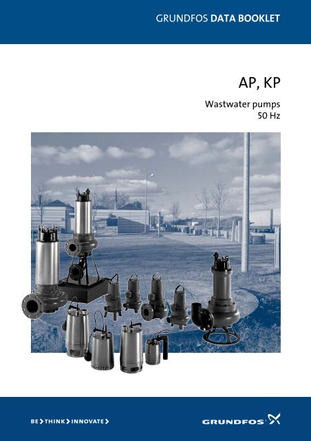
AP, KP<br />
Wastwater pumps<br />
50 Hz
Contents<br />
General <strong>data</strong><br />
Performance range Page 3<br />
Applications Page 5<br />
Examples of application Page 5<br />
Pump overview Page 6<br />
Type key for AP pumps Page 6<br />
Type key for KP pumps Page 6<br />
Construction Page 7<br />
Installation Page 7<br />
Sectional drawing Page 7<br />
AP10 Ex-version Page 91<br />
AP30 Ex-version Page 91<br />
AP51 Ex-version Page 91<br />
AP65 Vortex Ex-version Page 91<br />
AP70 Ex-version Page 91<br />
AP80 Vortex Ex-version Page 92<br />
AP100 Ex-version Page 93<br />
<strong>Technical</strong> <strong>data</strong><br />
KP Page 8<br />
AP10 Page 11<br />
AP12 Page 14<br />
AP30 Page 17<br />
AP35 Page 20<br />
AP35B Page 23<br />
AP50 Page 26<br />
AP50B Page 29<br />
AP51 Page 32<br />
AP65 Vortex Page 35<br />
AP70 Page 40<br />
Control box Page 44<br />
AP80 Vortex Page 45<br />
AP100 Page 57<br />
Accessories<br />
LC 107, LCD 107 Page 71<br />
LC 108, LCD 108 Page 72<br />
Dimensions Page 73<br />
Level switches Page 73<br />
Explosion protection unit, LC Ex 4 Page 73<br />
Accessories for AP, KP stainless steel pumps Page 74<br />
Accessories for cast iron AP pumps Page 75<br />
Level controllers and accessories Page 78<br />
Free-standing installation or portable Page 79<br />
Installation on auto-coupling Page 79<br />
Vertical dry installation (D) Page 79<br />
Pipe dimensions Page 80<br />
Product range<br />
KP 150 Page 81<br />
KP 250 Page 82<br />
KP 350 Page 83<br />
AP10 Page 84<br />
AP12 Page 84<br />
AP30 Page 85<br />
AP35 Page 85<br />
AP35B Page 85<br />
AP50 Page 86<br />
AP50B Page 86<br />
AP51 Page 87<br />
AP65 Vortex Page 88<br />
AP70 Page 88<br />
AP80 Vortex standard version Page 89<br />
AP100 standard version Page 90<br />
2
General <strong>data</strong><br />
AP, KP<br />
Performance range<br />
H<br />
[m]<br />
18<br />
16<br />
14<br />
12<br />
10<br />
8<br />
6<br />
4<br />
2<br />
0<br />
KP<br />
AP12<br />
Drainage pumps<br />
AP10<br />
H<br />
[m]<br />
11<br />
10<br />
9<br />
8<br />
7<br />
6<br />
5<br />
4<br />
3<br />
2<br />
1<br />
0<br />
AP50<br />
AP35<br />
Wastewater and<br />
sewage pumps<br />
0 2 4 6 8 10 12 14 Q [l/s]<br />
0 1 2 3 4 5 6 7 8 9 10 Q [l/s]<br />
0 5 10 15 20 25 30 35 40 45 50 Q [m³/h]<br />
TM00 3546 3999<br />
0 5 10 15 20 25 30 Q [m³/h]<br />
H<br />
[m]<br />
18<br />
16<br />
Wastewater and<br />
sewage pumps<br />
14<br />
12<br />
AP30<br />
10<br />
8<br />
AP51<br />
6<br />
4<br />
2<br />
0<br />
0 2 4 6 8 10 12 14 16 18 Q [l/s]<br />
0 10 20 30 40 50 60 Q [m³/h]<br />
TM00 3548 3300<br />
TM00 3547 3999<br />
3
General <strong>data</strong><br />
AP, KP<br />
H<br />
[m]<br />
16<br />
14<br />
Wastewater and<br />
sewage pumps<br />
H<br />
[m]<br />
40<br />
20<br />
Vortex pumps<br />
12<br />
10<br />
8<br />
6<br />
AP50B<br />
10<br />
6<br />
4<br />
AP80.V<br />
4<br />
2<br />
0<br />
AP35B<br />
0 1 2 3 4 5 6 7 8 9 Q [l/s]<br />
0 5 10 15 20 25 30 Q [m³/h]<br />
TM01 9544 2100<br />
2<br />
1<br />
0 5 10 15 20 25 Q [l/s]<br />
0 20 40 60 80 Q [m³/h]<br />
TM01 6234 0803<br />
H<br />
[m]<br />
20<br />
Vortex pumps<br />
10<br />
8<br />
6<br />
4<br />
AP65.100.V<br />
3<br />
2<br />
1<br />
AP65.65.V<br />
0<br />
0 5 10 15 20 25 30 35 40 45 50 55 60 65 70 Q [l/s]<br />
0 50 100 150 200 Q [m³/h]<br />
TM01 9666 2400<br />
H<br />
[m]<br />
32<br />
Sewage pumps<br />
24<br />
16<br />
8<br />
AP70<br />
AP100<br />
0<br />
0 10 20 30 40 50 60 70 80 90 100 110 Q [l/s]<br />
0 50 100 150 200 250 300 350 Q [m³/h]<br />
TM00 3549 0803<br />
4
General <strong>data</strong><br />
AP, KP<br />
Applications<br />
The KP and AP pumps are suitable for temporary as well<br />
as permanent free-standing installation. Furthermore<br />
AP pumps are suitable for installation on an autocoupling<br />
at the bottom of a pit with guide rails going to<br />
the top.<br />
The AP100 pump is available for dry pit installation.<br />
The pumps are designed for intermittent operation.<br />
pH value for KP pumps: 4 to 9.<br />
pH value for AP pumps: 4 to 10.<br />
Maximum density: 1.100 kg/m 3<br />
Maximum installation depth below water level: 10 m.<br />
For permanent installation, level controllers are available:<br />
LC 107 and LC 108 for one-pump installations and<br />
LCD 107 and LCD 108 for two-pump installations.<br />
Explosion-proof versions of the AP pumps are available<br />
for applications involving the risk of explosion.<br />
Classification: EN 50 014/18/19/20 - 1977 (BS 5501), class<br />
EEx d(e) (ib) IIB T4.<br />
Examples of application<br />
KP<br />
AP<br />
10<br />
AP<br />
12<br />
AP<br />
30<br />
AP<br />
35<br />
AP<br />
35B<br />
AP<br />
50<br />
AP<br />
50B<br />
AP<br />
51<br />
AP65<br />
Vortex<br />
AP<br />
70<br />
AP80<br />
Vortex<br />
Max. liquid temperature 50°C 40°C 55°C 40°C 55°C 40°C 55°C 40°C 40°C 40°C 40°C 40°C 40°C<br />
Pumping of wastewater from rivers and lakes ! ! ! ! ! ! ! " " " " "<br />
Pumping of drainage water and flood water ! ! ! ! ! ! ! ! " " " " "<br />
Pumping of surface rainwater ! ! ! ! ! ! ! ! ! " ! " "<br />
Pumping of ditch and excavation drainage water ! ! ! ! ! ! ! ! ! " ! "<br />
Pumping of drainage water from<br />
garage sprinkler systems<br />
! " ! " " " " ! " ! " "<br />
Mobile use for contractors, installers and industry<br />
! ! ! ! ! ! ! ! " " " "<br />
Filling/emptying of containers ! ! ! ! ! ! ! ! ! " "<br />
Transfer of liquids in industry, etc. ! ! ! ! ! ! ! ! ! ! ! !<br />
Pumping of effluents from tunnels,<br />
underground garages etc.<br />
! ! ! ! ! ! ! ! ! ! ! !<br />
Pumping of sewage from single and multi-family<br />
dwellings<br />
! ! ! !<br />
Pressurized pumping of sewage from camp sites,<br />
service areas and remote buildings<br />
!<br />
Pressurized pumping of sewage from public<br />
buildings and small factories<br />
!<br />
Pumping of sewage from private toilets, showers,<br />
swimming pools etc. below sewer level<br />
! ! ! ! ! ! "<br />
Pumping of wastewater from single and multifamily<br />
homes, camp sites and sports stadiums<br />
" " " ! ! !<br />
Pumping of sewage in municipal applications ! ! ! !<br />
Pumping of sewage from hotels, restaurants, cinemas,<br />
schools and public buildings<br />
! ! ! !<br />
Pumping of wastewater from underground stations<br />
and public swimming pools<br />
! ! ! !<br />
● = Recommended pump type<br />
❍ = Alternative pump type<br />
AP<br />
100<br />
5
General <strong>data</strong><br />
AP, KP<br />
Pump overview<br />
Pump range<br />
Type key for AP pumps<br />
Free passage<br />
[mm]<br />
Impeller type<br />
Number of motor poles<br />
Explosion-proof versions<br />
available<br />
KP 10 Semi-open 2 No<br />
AP10 10 Semi-open 2 Yes<br />
AP12 12 Semi-open 2 No<br />
AP30 30 Open single-channel 2 Yes<br />
AP35 35 Vortex 2 No<br />
AP35B 35 Vortex 2 No<br />
AP50 50 Vortex 2 No<br />
AP50B 50 Vortex 2 No<br />
AP51 50 Single-channel 2 Yes<br />
AP65 Vortex 65 Vortex 4 Yes<br />
AP70 70 Single-channel 4 Yes<br />
AP80 Vortex 80 Vortex 2 or 4 Yes<br />
AP100 100<br />
Single channel<br />
or two-channel<br />
4 or 6 Yes<br />
Example AP 30 .50 .07 /1 A .3 .V .D H .Ex<br />
AP:<br />
AP pump range<br />
10-130:<br />
G:<br />
B<br />
Max. free passage [mm]<br />
With cutter system (APG grinder pumps)<br />
Basic<br />
40-130: Nominal diameter of discharge port [mm]<br />
0.4 - 450: Power output P 2 /100 [W]<br />
/1 Blank or 1 = Standard performance .<br />
Digit 1 indicates that the pump type is available<br />
with a reduced-diameter impeller.<br />
2 = Reduced-diameter impeller meaning reduced<br />
performance<br />
A: With level switch<br />
1:<br />
none or 3:<br />
Single-phase voltage supply<br />
Three-phase voltage supply<br />
V: With vortex impeller<br />
D: For dry installation<br />
H: For horizontal installation<br />
Ex:<br />
Explosion-proof<br />
Type key for KP pumps<br />
Example KP 150 A -1<br />
KP:<br />
Pump range<br />
150:<br />
250:<br />
350:<br />
150 W motor power output<br />
250 W motor power output<br />
350 W motor power output<br />
A:<br />
AV:<br />
M:<br />
1:<br />
3:<br />
With float switch<br />
With vertical level switch<br />
Without level switch<br />
Single-phase voltage supply<br />
Three-phase voltage supply<br />
6
General <strong>data</strong><br />
AP, KP<br />
Construction<br />
Vertical, single-stage, submersible centrifugal pumps<br />
with horizontal or vertical discharge port designed for<br />
free-standing installation or installation by means of an<br />
auto-coupling guide rail system or for pit installation.<br />
The pumps are directly connected to an asynchronous<br />
submersible motor for 1 x 230 V +6/–10%, 3 x 230 V<br />
+6/–10% or 3 x 400 V +6/–10%, 50 Hz.<br />
Enclosure class: IP 68.<br />
Insulation class: F (155°C).<br />
Stainless steel pumps<br />
Single-phase pumps incorporate thermal overload<br />
protection and require no additional motor protection.<br />
Three-phase pumps must be connected to a motor<br />
starter.<br />
Cast iron pumps<br />
APG pumps have a built-in thermal protection which<br />
cuts off the motor in case of overload. The motor restarts<br />
automatically; Ex-pumps, however, require manual<br />
restart.<br />
Three-phase Ex-pumps have a thermal switch in the<br />
motor windings. The thermal switch is to be connected<br />
to the control circuit of a motor starter. Ex-pumps<br />
require manual restart.<br />
Some three-phase pumps have a thermal switch in the<br />
motor windings.<br />
Installation<br />
The pumps are suitable for free-standing installation as<br />
well as installation on an auto-coupling guide rail<br />
system, which is available as an accessory.<br />
AP80 Vortex and AP100 pumps are suitable for vertical<br />
or horizontal dry pit installation.<br />
Pumps in permanent submersible installations can be<br />
installed by means of a stationary auto-coupling at the<br />
bottom of the pit. Two guide rails going to the top of the<br />
pit ensure that the pump is positioned correctly when<br />
lowered from the top of the pit down to the autocoupling<br />
and connected to the pipe system. Due to this<br />
system, the pump can easily be pulled up for service.<br />
Pumps for vertical dry pit installation can be installed by<br />
means of a stationary dry pit stand with suction bend.<br />
For free-standing installation the AP70 and AP100<br />
pumps must be fitted with a base stand, see accessories.<br />
Sectional drawing<br />
AP51.65.22.3(Ex)<br />
TM01 2559 2098<br />
7
<strong>Technical</strong> <strong>data</strong><br />
Drainage pumps<br />
KP<br />
KP<br />
The KP pump is designed for liquid transfer and drainage<br />
of clean or slightly dirty waste water with the pump<br />
completely or partly submerged in the liquid.<br />
• drainage of cellars or buildings,<br />
• pumping of domestic waste water without toilet<br />
waste,<br />
• groundwater lowering,<br />
• emptying applications, eg. in pools,<br />
tanks and vessels and<br />
• pumping applications within agriculture, dairy<br />
industry, horticulture and process industry.<br />
Approvals<br />
Z-53.3-408 according to Institut für Bautechnik, Berlin<br />
Pumped liquids<br />
Pumps without level switch or with float switch:<br />
The pump is suitable for the pumping of<br />
• clean, non-aggressive water and<br />
• slightly dirty (grey) waste water.<br />
If the pump has been used for other liquids than clean<br />
water, it should be flushed through with clean water<br />
immediately after use. The open impeller construction<br />
ensures a free passage of solids up to a diameter of ø10<br />
mm.<br />
Pumps with vertical level switch:<br />
The pump must only be used for the pumping of clean<br />
ground water and drain water.<br />
Operating range<br />
Installation depth:<br />
Min. liquid temperature:<br />
Max. liquid temperature<br />
at continuous operation:<br />
Max. 10 metres below liquid<br />
level.<br />
0°C.<br />
50°C.<br />
During continuous pumping the suction strainer must<br />
always be completely covered by the liquid.<br />
Max. liquid temperature: 70°C for periods not exceeding<br />
2 minutes at intervals of at least 30 minutes.<br />
TM01 7145 4099<br />
Discharge<br />
KP 150, KP 250 and KP 350:<br />
Rp 1¼<br />
Pump sleeve and housing<br />
Single-stage, submersible, stainless steel, drainage<br />
pump in a robust design with upwards-pointing<br />
discharge port placed on top of the pump.<br />
The water enters the pump through the holes of the<br />
suction strainer preventing the passage of large solids.<br />
The sturdy impeller has single curved vanes with<br />
bevelled front edges that prevent fibres from jamming<br />
the impeller. The guide vanes in the pump housing not<br />
only guide the liquid but also lift sand grains into the<br />
liquid flow and thus prevent blocking by sand.<br />
The outer casing is made in one piece. The mains cable<br />
and the cable of the level switch are combined in one<br />
vulcanized and watertight plug, which is secured to the<br />
socket of the hermetically sealed stator housing.<br />
Motor<br />
The motor is a single- or three-phase, asynchronous<br />
canned motor with liquid-filled rotor chamber and<br />
water lubricated bearings. The motor is cooled by the<br />
pumped liquid around the motor.<br />
Enclosure class: IP 68.<br />
Insulation class: F.<br />
The motor incorporates automatic overload protection<br />
which cuts out the motor in case of overload. When it<br />
has cooled to normal temperature, the motor will restart<br />
automatically.<br />
Materials<br />
Components<br />
Materials<br />
DIN<br />
W.-Nr.<br />
AISI<br />
Outer casing Stainless steel 1.4301 304<br />
Pump housing Stainless steel 1.4301 304<br />
Suction strainer Stainless steel 1.4301 304<br />
Impeller Stainless steel 1.4301 304<br />
Shaft Stainless steel 1.4057 431<br />
Stator housing Stainless steel 1.4301 304<br />
Guide vanes Stainless steel 1.4301 304<br />
Bearings<br />
Carbon<br />
O-rings<br />
Seal rings<br />
NBR<br />
Cables<br />
H 07 RN-F<br />
8
min. L3<br />
•<br />
•<br />
•<br />
•<br />
•<br />
•<br />
• •<br />
•<br />
•<br />
•<br />
•<br />
•<br />
•<br />
• •<br />
•<br />
•<br />
•<br />
•<br />
•<br />
•<br />
•<br />
•<br />
•<br />
•<br />
•<br />
•<br />
•<br />
•<br />
•<br />
•<br />
•<br />
•<br />
•<br />
•<br />
•<br />
•<br />
•<br />
•<br />
•<br />
•<br />
•<br />
• •<br />
•<br />
•<br />
•<br />
•<br />
•<br />
•<br />
•<br />
•<br />
• •<br />
•<br />
•<br />
•<br />
•<br />
•<br />
•<br />
•<br />
•<br />
• •<br />
•<br />
•<br />
• •<br />
•<br />
•<br />
•<br />
•<br />
•<br />
•<br />
• •<br />
•<br />
•<br />
•<br />
•<br />
•<br />
•<br />
•<br />
•<br />
•<br />
•<br />
•<br />
•<br />
•<br />
•<br />
•<br />
•<br />
•<br />
•<br />
•<br />
•<br />
•<br />
•<br />
• •<br />
•<br />
•<br />
•<br />
•<br />
•<br />
•<br />
•<br />
•<br />
•<br />
•<br />
•<br />
•<br />
•<br />
•<br />
•<br />
•<br />
•<br />
• •<br />
•<br />
•<br />
•<br />
• •<br />
•<br />
•<br />
•<br />
•<br />
•<br />
•<br />
•<br />
•<br />
•<br />
•<br />
• •<br />
•<br />
•<br />
•<br />
•<br />
•<br />
•<br />
• •<br />
•<br />
•<br />
•<br />
•<br />
•<br />
•<br />
•<br />
•<br />
•<br />
•<br />
•<br />
•<br />
•<br />
•<br />
•<br />
•<br />
•<br />
•<br />
•<br />
•<br />
•<br />
•<br />
• •<br />
•<br />
•<br />
•<br />
•<br />
•<br />
•<br />
•<br />
•<br />
•<br />
•<br />
•<br />
•<br />
•<br />
•<br />
•<br />
•<br />
•<br />
• •<br />
•<br />
•<br />
•<br />
• •<br />
•<br />
•<br />
•<br />
•<br />
•<br />
•<br />
•<br />
•<br />
•<br />
•<br />
•<br />
• •<br />
•<br />
•<br />
•<br />
•<br />
•<br />
•<br />
•<br />
• •<br />
•<br />
•<br />
•<br />
•<br />
•<br />
• • • •<br />
• •<br />
•<br />
•<br />
•<br />
•<br />
•<br />
•<br />
•<br />
•<br />
•<br />
•<br />
•<br />
•<br />
•<br />
•<br />
•<br />
•<br />
•<br />
•<br />
•<br />
•<br />
•<br />
•<br />
•<br />
•<br />
•<br />
•<br />
•<br />
• •<br />
• •<br />
•<br />
•<br />
•<br />
•<br />
•<br />
•<br />
•<br />
• • •<br />
•<br />
•<br />
•<br />
•<br />
• •<br />
•<br />
•<br />
•<br />
• •<br />
•<br />
•<br />
•<br />
•<br />
•<br />
•<br />
•<br />
•<br />
•<br />
•<br />
•<br />
•<br />
•<br />
•<br />
•<br />
•<br />
• •<br />
•<br />
•<br />
• •<br />
•<br />
•<br />
•<br />
•<br />
•<br />
•<br />
•<br />
•<br />
•<br />
•<br />
•<br />
•<br />
•<br />
•<br />
•<br />
•<br />
•<br />
•<br />
•<br />
• •<br />
•<br />
•<br />
•<br />
• •<br />
•<br />
•<br />
•<br />
•<br />
•<br />
•<br />
•<br />
•<br />
•<br />
•<br />
• • • •<br />
• • • •<br />
• •<br />
• • •<br />
•<br />
•<br />
•<br />
•<br />
•<br />
•<br />
•<br />
•<br />
•<br />
•<br />
•<br />
•<br />
•<br />
•<br />
•<br />
•<br />
•<br />
•<br />
•<br />
•<br />
•<br />
•<br />
•<br />
•<br />
•<br />
•<br />
•<br />
•<br />
•<br />
•<br />
•<br />
•<br />
•<br />
• •<br />
•<br />
•<br />
•<br />
•<br />
•<br />
•<br />
•<br />
•<br />
•<br />
•<br />
•<br />
• •<br />
•<br />
•<br />
•<br />
•<br />
•<br />
•<br />
•<br />
•<br />
•<br />
•<br />
•<br />
•<br />
•<br />
•<br />
•<br />
•<br />
• •<br />
•<br />
•<br />
•<br />
•<br />
•<br />
•<br />
•<br />
•<br />
•<br />
•<br />
•<br />
•<br />
•<br />
•<br />
•<br />
•<br />
•<br />
•<br />
•<br />
•<br />
•<br />
•<br />
• •<br />
•<br />
•<br />
•<br />
•<br />
•<br />
•<br />
•<br />
•<br />
•<br />
•<br />
•<br />
•<br />
•<br />
•<br />
•<br />
•<br />
•<br />
• •<br />
•<br />
•<br />
•<br />
•<br />
•<br />
•<br />
•<br />
•<br />
•<br />
•<br />
•<br />
•<br />
•<br />
•<br />
•<br />
•<br />
• •<br />
•<br />
•<br />
•<br />
•<br />
•<br />
•<br />
•<br />
•<br />
•<br />
•<br />
•<br />
•<br />
•<br />
• •<br />
•<br />
•<br />
•<br />
•<br />
•<br />
•<br />
•<br />
•<br />
•<br />
•<br />
•<br />
•<br />
•<br />
•<br />
•<br />
•<br />
•<br />
•<br />
•<br />
• •<br />
•<br />
•<br />
•<br />
•<br />
•<br />
•<br />
•<br />
•<br />
•<br />
•<br />
•<br />
•<br />
•<br />
•<br />
•<br />
<strong>Technical</strong> <strong>data</strong><br />
Drainage pumps<br />
KP<br />
p<br />
[kPa]<br />
80<br />
H<br />
[m]<br />
9<br />
8<br />
KP 350<br />
KP 250<br />
KP<br />
50 Hz<br />
ISO 2548 +/- 10 %<br />
7<br />
60<br />
6<br />
5<br />
KP 150<br />
40<br />
4<br />
3<br />
20<br />
2<br />
1<br />
0<br />
0<br />
0 2 4 6 8 10 12 Q [m³/h]<br />
0 1 2 3 Q [l/s]<br />
TM01 2059 0803<br />
Pump type<br />
Voltage<br />
P 1<br />
I n<br />
Dimensions [mm]<br />
Weight<br />
[W]<br />
[A]<br />
H B1 B2 L1 L2 L3 [kg]<br />
KP 150 1 x 220-230 V 300 1.3 225 149 31 350 400 70 6.3<br />
KP 150 1 x 230-240 V 300 1.3 225 149 31 350 400 70 6.3<br />
KP 250 1 x 220-230 V 480 2.3 225 149 31 350 400 70 7.2<br />
KP 250 1 x 230-240 V 480 2.2 225 149 31 350 400 70 7.2<br />
KP 250 3 x 380-415 V 480 0.8 225 149 31 350 400 70 7.2<br />
KP 350 1 x 220-240 V 700 3.2 235 149 31 350 410 70 8.0<br />
KP 350 3 x 380-400 V 700 1.3 235 149 31 350 410 70 8.0<br />
With float switch<br />
With vertical level switch<br />
H<br />
2<br />
min. L<br />
min. L1<br />
400 mm<br />
Rp 11/<br />
4<br />
2<br />
B<br />
1<br />
B<br />
TM00 1803 1597<br />
ø 250 mm<br />
TM01 1109 1098<br />
9
<strong>Technical</strong> <strong>data</strong><br />
Drainage pumps<br />
KP<br />
Installation<br />
Pumps without level switch or with float switch can be<br />
used in vertical position with the discharge port uppermost<br />
or in horizontal or tilted position with the<br />
discharge port as the highest point of the pump.<br />
Pumps with vertical level switch must be used in vertical<br />
position.<br />
TM00 1548 0493<br />
Level switches<br />
A level switch, which gives impulses to start/stop<br />
between two levels of liquid, is connected to pumps<br />
intended for automatic operation. This type of installation<br />
requires a non-return valve in the discharge pipe or<br />
in the pump. The pumps are available with two different<br />
types of level switches.<br />
Min. liquid level: – manual operation: 14 mm.<br />
– automatic operation: See below.<br />
Pumps with float switch:<br />
A clamp on the handle of the pump holds the cable of the<br />
level switch. The difference in level between start and<br />
stop can be adjusted by changing the free cable length<br />
between the handle of the pump and the level switch.<br />
Dimensions for KP 350 are marked with "#".<br />
Float switch<br />
Max.<br />
Max. 150 mm<br />
150mm<br />
TM01 1492 4697<br />
••••••••<br />
••••••••<br />
••••••••••<br />
••••••••••<br />
•••••••••<br />
••••••••<br />
•••••••••••<br />
••••••••••<br />
••••••••••••<br />
•••••••••••<br />
••••••••••<br />
••••••••••••••<br />
••••••••••••<br />
•••••••••••<br />
Start<br />
225mm<br />
The KP pump is well suited for permanent installation.<br />
Stop<br />
100 mm<br />
100mm<br />
110 mm#<br />
TM02 1552 2599<br />
Pumps with vertical level switch:<br />
For pumps with vertical level switch, the difference in<br />
level between start and stop is not adjustable.<br />
Dimensions for KP 350 are marked with "#".<br />
Vertical level switch<br />
80 mm<br />
80 mm<br />
100 mm<br />
110<br />
100<br />
mm#<br />
mm<br />
Start<br />
Start<br />
Stop<br />
Stop<br />
TM01 1108 3297<br />
10
<strong>Technical</strong> <strong>data</strong><br />
AP10<br />
AP10<br />
Impeller<br />
The impeller is a semi-open cast iron impeller with a<br />
clearance of 10 mm in the pump housing. Cast iron is<br />
chosen as it is resistant towards mechanically wearing<br />
particles.<br />
The pumps are used for pumping wastewater, sludgecontaining<br />
water, ground water and surface water in<br />
places such as<br />
• sumps,<br />
• shafts,<br />
• ducts,<br />
• tunnels,<br />
• excavations,<br />
• basements,<br />
• cellars and<br />
• underground car parks.<br />
AP10 pumps are ideal for general flood relief applications<br />
and for miscellaneous industrial applications.<br />
Pump and stator housing<br />
The pump housing and stator housing are made of cast<br />
iron.<br />
The stator housing is dry, i.e. not oil-filled.<br />
Discharge<br />
All AP10 pumps have a horizontal discharge port for<br />
threaded connection.<br />
AP10.50.Ex: R 2.<br />
AP10.65: R 2½.<br />
Shaft and bearings<br />
The shaft is made of stainless steel and rotates in maintenance-free<br />
prelubricated ball bearings.<br />
The lower bearing is a double-row ball bearing.<br />
TM02 0125 3900<br />
An adjustable cast iron wear plate is fitted at the inlet<br />
side of the impeller.<br />
Shaft seals<br />
AP10.50.12.3Ex:<br />
AP10.65.21:<br />
Motor cable<br />
Standard pumps 10 m:<br />
Ex-pumps 10 m:<br />
Materials<br />
Control box<br />
Combination of mechanical shaft seal<br />
and lip seal.<br />
The primary shaft seal has silicon<br />
carbide/silicon carbide seal faces. The<br />
secondary shaft seal is a lip seal. The<br />
chamber between the shaft seals is<br />
filled with 0.04 litre of oil.<br />
Two mechanical bellows seals with<br />
silicon carbide/silicon carbide seal<br />
faces. The chamber between the shaft<br />
seals is filled with 1.2 litre of oil.<br />
H07RNF.<br />
H07RNF - PLUS.<br />
Description<br />
Materials<br />
DIN<br />
W.-Nr.<br />
AISI/ASTM<br />
Strainer Cast iron EN-GJL-250 0.6025 ASTM 35B<br />
Stator housing Cast iron EN-GJL-250 0.6025 ASTM 35B<br />
Pump housing Cast iron EN-GJL-250 0.6025 ASTM 35B<br />
Wear plate Cast iron EN-GJL-250 0.6025 ASTM 35B<br />
Impeller Cast iron EN-GJL-250 0.6025 ASTM 35B<br />
Shaft Stainless steel 1.4104 AISI 430F<br />
Bearings<br />
Heavy-duty prelubricated ball bearings<br />
Screws Stainless steel 1.4301 AISI 304<br />
Oil<br />
Shell Ondina 15, non-toxic<br />
Further information about control box, float switch, and<br />
level control, see page 44.<br />
TM00 3553 5093<br />
11
<strong>Technical</strong> <strong>data</strong><br />
AP10<br />
p<br />
[kPa]<br />
200<br />
H<br />
[m]<br />
22<br />
20<br />
AP10.65.21.3<br />
AP10<br />
50 Hz<br />
ISO 9906 Annex A<br />
18<br />
AP10.50.12.3Ex<br />
160<br />
16<br />
14<br />
S<br />
120<br />
12<br />
10<br />
80<br />
8<br />
E<br />
A<br />
6<br />
C<br />
40<br />
0<br />
4<br />
2<br />
0<br />
0 5 10 15 20 25 30 35 40 45 50 55 Q [m³/h]<br />
B<br />
TM01 2538 2098<br />
0 2 4 6 8 10 12 14 16 Q [l/s]<br />
P1<br />
[hp]<br />
3<br />
P1<br />
[kW]<br />
2.4<br />
2.0<br />
AP10.65.21.3<br />
2<br />
1<br />
0<br />
1.6<br />
AP10.50.12.3Ex<br />
1.2<br />
0.8<br />
0.4<br />
0.0<br />
0 5 10 15 20 25 30 35 40 45 50 55 Q [m³/h]<br />
TM00 3454 0803<br />
Pump type<br />
Voltage<br />
Dimensions [mm]<br />
P 1 P 2 n In<br />
[kW] [kW] [min -1 Cos ϕ<br />
I Weight#<br />
] [A]<br />
-------- start<br />
A B C E S [kg]<br />
I n<br />
AP10.50.12.3.Ex 3 x 400 V 1.60 1.20 2850 2.9 0.84 4.6 426 300 87 161 R 2 30<br />
AP10.50.12.3.Ex 3 x 230 V 1.60 1.20 2850 2.9 0.84 4.6 426 300 87 161 R 2 30<br />
AP10.65.21.3 3 x 400 V 2.50 2.10 2800 4.5 0.84 4.6 525 380 108 198 R 2½ 27<br />
AP10.65.21.3 3 x 230 V 2.50 2.10 2800 7.8 0.84 4.7 525 380 108 198 R 2½ 27<br />
AP10.65.21.A.3 3 x 400 V 2.50 2.10 2800 4.5 0.84 4.6 525 380 108 198 R 2½ 27<br />
AP10.65.21.A.3 3 x 230 V 2.50 2.10 2800 7.8 0.84 4.7 525 380 108 198 R 2½ 27<br />
#Pump inclusive of cable.<br />
12
‹<br />
‹<br />
‹<br />
‹<br />
‹<br />
‹<br />
‹<br />
‹<br />
‹<br />
‹<br />
‹<br />
‹<br />
‹<br />
‹<br />
‹<br />
‹<br />
‹ ‹<br />
‹<br />
‹<br />
‹<br />
‹ ‹<br />
‹<br />
‹ ‹ ‹<br />
‹<br />
‹<br />
‹<br />
‹<br />
‹<br />
‹<br />
‹<br />
‹<br />
‹<br />
‹ ‹<br />
‹<br />
‹<br />
‹<br />
‹<br />
‹<br />
‹<br />
‹<br />
‹<br />
‹ ‹<br />
‹<br />
‹<br />
‹<br />
‹ ‹<br />
‹<br />
‹ ‹<br />
‹<br />
‹<br />
‹<br />
‹<br />
‹ ‹<br />
‹ ‹<br />
‹<br />
‹<br />
‹<br />
‹<br />
‹<br />
‹<br />
‹<br />
‹<br />
‹<br />
‹<br />
‹<br />
‹<br />
‹<br />
‹ ‹<br />
‹<br />
‹<br />
‹<br />
‹<br />
‹<br />
‹ ‹<br />
‹<br />
‹<br />
‹<br />
‹<br />
‹<br />
‹<br />
‹<br />
‹<br />
‹<br />
‹<br />
‹ ‹<br />
‹<br />
‹<br />
‹ ‹<br />
‹<br />
‹<br />
‹ ‹ ‹ ‹<br />
‹ ‹ ‹<br />
‹<br />
‹<br />
‹<br />
‹<br />
‹<br />
‹<br />
‹<br />
‹<br />
‹<br />
‹<br />
‹<br />
‹<br />
‹<br />
‹ ‹<br />
‹<br />
‹<br />
‹<br />
‹<br />
‹<br />
‹<br />
‹<br />
‹<br />
‹<br />
‹ ‹<br />
‹<br />
‹<br />
‹<br />
‹<br />
‹<br />
‹<br />
‹<br />
‹<br />
‹<br />
‹<br />
‹<br />
‹<br />
‹<br />
‹<br />
‹<br />
‹<br />
<strong>Technical</strong> <strong>data</strong><br />
AP10<br />
AP10 installations<br />
A<br />
C<br />
B<br />
F<br />
D<br />
T<br />
E<br />
S<br />
V<br />
U<br />
J<br />
I<br />
G<br />
M<br />
M<br />
N<br />
K<br />
L<br />
O<br />
TM01 2539 2098<br />
P<br />
R<br />
P<br />
TM01 2540 2098<br />
One-pump installation on auto-coupling<br />
Pump type A B C D E F G I J K L M N O P S T U V<br />
AP10.50.12.Ex ø600 ø600 245 300 45 45 65 115 74 150 450 200 300 700 500 Rp 2 ½" 160 295<br />
AP10.65.21 ø600 ø600 300 297 70 60 82 180 32 150 510 220 350 650 500 DN65 1" 160 250<br />
Two-pump installation on auto-coupling<br />
Pump type A B C D E F G I J K L M N O P R S T U V<br />
AP10.50.12.Ex 445 600 245 135 45 45 65 115 74 150 450 200 300 700 335 330 Rp 2 ½" 160 295<br />
AP10.65.21 600 975 300 297 70 60 82 180 32 150 510 220 375 875 435 380 DN65 1" 160 250<br />
13
<strong>Technical</strong> <strong>data</strong><br />
AP12<br />
AP12<br />
The riser pipe has a number of holes which enable efficient<br />
cooling of the motor during operation. The cable<br />
entry is of the socket and plug connection type, which<br />
makes quick and easy dismantling possible.<br />
Discharge port<br />
All AP12 pumps have a threaded vertical discharge port.<br />
AP12.40: Rp 1½.<br />
AP12.50: Rp 2.<br />
The AP12 pump is a single-stage submersible pump<br />
designed for the pumping of drainage water. The pump<br />
is suitable for the following applications<br />
• ground water lowering,<br />
• pumping in drainage pits,<br />
• pumping in surface water pits with inflow from roof<br />
gutters, shafts, tunnels, etc.,<br />
• emptying of ponds, tanks, etc. and<br />
• maximum particle size: 12 mm.<br />
Approvals<br />
PA-I no. 4104 VDE.<br />
Automatic operation<br />
The pump is available for automatic as well as manual<br />
operation and can be installed in a permanent installation<br />
or used as a portable pump. The pump is available:<br />
• with level switch fitted for automatic ON/OFF operation<br />
between two liquid levels<br />
(single-phase pumps);<br />
• with separate level switch and control box for automatic<br />
ON/OFF operation between two liquid levels<br />
(three-phase pumps);<br />
• without level switch for manual ON/OFF operation.<br />
Pumps fitted with level switches can also be used for<br />
manual ON/OFF operation. In this case the level switch<br />
must be secured in an upwards-pointing position.<br />
Pump sleeve and housing<br />
The stainless steel pump sleeve is made in one piece and<br />
equipped with an insulated carrying handle. The suction<br />
strainer is clipped on to the pump housing and can easily<br />
be removed for maintenance. The strainer not only<br />
prevents the passage of large solids but also ensures a<br />
slow flow into the pump. As a result, most impurities<br />
will be deposited outside the pump.<br />
The stainless steel pump housing is fitted with an<br />
internal riser pipe ensuring high efficiency.<br />
TM00 5738 0895<br />
Shaft and bearings<br />
The shaft is made of stainless steel and rotates in maintenance-free<br />
prelubricated ball bearings.<br />
Impeller<br />
The stainless steel impeller is a semi-open impeller with<br />
L-shaped blades and a clearance of 12 mm. The blades<br />
are curved backwards to reduce any harmful effect from<br />
solid particles and to reduce the power consumption.<br />
Shaft seal<br />
The shaft seal is a combination of a mechanical shaft<br />
seal of the bellows type and a lip seal with 60 ml oil<br />
between them. The mechanical shaft seal of AP12 pumps<br />
has silicone carbide seal faces.<br />
Motor cable<br />
Standard pumps 10 m:<br />
Materials<br />
H07RNF.<br />
Description<br />
Materials<br />
DIN<br />
W.-Nr.<br />
AISI<br />
Pump housing Stainless steel 1.4301 304<br />
Riser pipe Stainless steel 1.4301 304<br />
Impeller Stainless steel 1.4301 304<br />
Pump sleeve Stainless steel 1.4401 316<br />
Shaft Stainless steel 1.4305<br />
Bearings<br />
Heavy-duty prelubricated ball bearings<br />
O-rings<br />
NBR rubber<br />
Screws Stainless steel 1.4301 304<br />
Oil<br />
Shell Ondina 15, non-toxic<br />
TM00 5477 0895<br />
14
<strong>Technical</strong> <strong>data</strong><br />
AP12<br />
p<br />
[kPa]<br />
160<br />
H<br />
[m]<br />
16<br />
.50.11.3<br />
AP12<br />
50 Hz<br />
ISO 9906 +/- 10%<br />
S<br />
B<br />
14<br />
.50.11.1<br />
120<br />
12<br />
.40.08<br />
10<br />
.40.06<br />
80<br />
8<br />
.40.04<br />
6<br />
A<br />
40<br />
0<br />
4<br />
2<br />
0<br />
0 5 10 15 20 25 30 35 Q [m³/h]<br />
0 2 4 6 8 10 Q [l/s]<br />
TM00 5523 0995<br />
P1<br />
[hp]<br />
P1<br />
[kW]<br />
2.0<br />
.50.11.3<br />
2<br />
1.6<br />
.50.11.1<br />
1.2<br />
.40.08<br />
1<br />
0<br />
.40.06<br />
0.8<br />
.40.04<br />
0.4<br />
0.0<br />
0 5 10 15 20 25 30 35 Q [m³/h]<br />
TM00 7212 0803<br />
Pump type<br />
Voltage<br />
Dimensions [mm]<br />
P 1<br />
P 2 In<br />
Cos ϕ<br />
I Weight<br />
[kW] [kW] [A]<br />
-------- start<br />
A B S<br />
[kg]<br />
I n<br />
AP12.40.04.1 1 x 230 V 0.8 0.4 3.0 0.99 3.8 321 216 Rp 1½ 11.0<br />
AP12.40.04.A1 1 x 230 V 0.8 0.4 3.0 0.99 3.8 321 216 Rp 1½ 11.0<br />
AP12.40.04.3 3 x 230 V 0.8 0.4 2.2 0.85 4.7 321 216 Rp 1½ 9.7<br />
AP12.40.04.A.3 3 x 230 V 0.8 0.4 2.2 0.85 4.7 321 216 Rp 1½ 12.0<br />
AP12.40.04.3 3 x 400 V 0.8 0.4 1.2 0.83 5.0 321 216 Rp 1½ 9.7<br />
AP12.40.04.A.3 3 x 400 V 0.8 0.4 1.2 0.83 5.0 321 216 Rp 1½ 12.0<br />
AP12.40.06.1 1 x 230 V 1.0 0.6 4.4 0.99 3.8 321 216 Rp 1½ 11.0<br />
AP12.40.06.A.1 1 x 230 V 1.0 0.6 4.4 0.99 3.8 321 216 Rp 1½ 11.0<br />
AP12.40.06.3 3 x 230 V 1.0 0.6 2.9 0.83 5.4 321 216 Rp 1½ 10.7<br />
AP12.40.06.A.3 3 x 230 V 1.0 0.6 2.9 0.83 5.4 321 216 Rp 1½ 13.0<br />
AP12.40.06.3 3 x 400 V 1.0 0.6 1.6 0.83 4.8 321 216 Rp 1½ 10.7<br />
AP12.40.06.A.3 3 x 400 V 1.0 0.6 1.6 0.83 4.8 321 216 Rp 1½ 10.7<br />
AP12.40.08.1 1 x 230 V 1.3 0.8 5.9 0.99 3.8 346 216 Rp 1½ 12.6<br />
AP12.40.08.A.1 1 x 230 V 1.3 0.8 5.9 0.99 3.8 346 216 Rp 1½ 12.6<br />
AP12.40.08.3 3 x 230 V 1.2 0.8 3.7 0.85 4.7 346 216 Rp 1½ 12.0<br />
AP12.40.08.A.3 3 x 230 V 1.2 0.8 3.7 0.85 4.7 346 216 Rp 1½ 14.3<br />
AP12.40.08.3 3 x 400 V 1.2 0.8 2.1 0.87 4.9 346 216 Rp 1½ 12.0<br />
AP12.40.08.A.3 3 x 400 V 1.2 0.8 2.1 0.87 4.9 346 216 Rp 1½ 14.3<br />
AP12.50.11.1 1 x 230 V 1.9 1.1 8.5 0.92 3.8 357 241 Rp 2 15.1<br />
AP12.50.11.A.1 1 x 230 V 1.9 1.1 8.5 0.92 3.8 357 241 Rp 2 15.1<br />
AP12.50.11.3 3 x 230 V 1.9 1.1 6.4 0.85 3.6 357 241 Rp 2 15.6<br />
AP12.50.11.A.3 3 x 230 V 1.9 1.1 6.4 0.85 3.6 357 241 Rp 2 17.9<br />
AP12.50.11.3 3 x 400 V 1.9 1.1 3.2 0.88 4.6 357 241 Rp 2 15.6<br />
AP12.50.11.A.3 3 x 400 V 1.9 1.1 3.2 0.88 4.6 357 241 Rp 2 17.9<br />
15
<strong>Technical</strong> <strong>data</strong><br />
AP12<br />
AP12 installations<br />
min. ø500<br />
TM00 5538 0995<br />
min. ø800<br />
TM00 5539 0995<br />
16
<strong>Technical</strong> <strong>data</strong><br />
AP30<br />
AP30<br />
Impeller<br />
The impeller is an open single-vane cast iron impeller<br />
with a clearance of 30 mm. Cast iron is chosen as it is<br />
resistant towards mechanically wearing particles.<br />
The pumps are used for pumping wastewater, sludgecontaining<br />
water, ground water and surface water in<br />
places such as<br />
• holiday homes,<br />
• single-family houses,<br />
• blocks of flats,<br />
• public buildings,<br />
• factories,<br />
• garages,<br />
• underground car parks and<br />
• car wash areas.<br />
Applications as under AP10, but where a larger impeller<br />
clearance is required.<br />
Pump and stator housing<br />
The pump housing and the stator housing are made of<br />
cast iron.<br />
The stator housing is dry, i.e. not oil-filled.<br />
Discharge<br />
All AP30 pumps have a horizontal R 2 discharge port for<br />
threaded connection.<br />
Shaft and bearings<br />
The shaft is made of stainless steel and rotates in maintenance-free<br />
prelubricated ball bearings.<br />
TM01 7174 4099<br />
An adjustable cast iron wear plate is fitted at the inlet<br />
side of the impeller.<br />
Shaft seal<br />
Combination of mechanical shaft seal and lip seal.<br />
The primary shaft seal have silicon carbide/silicon<br />
carbide seal faces.<br />
The secondary shaft seal is a lip seal. The chamber<br />
between the shaft seals is filled with oil.<br />
Standard pumps: 0.01 litre<br />
Ex-pumps:<br />
0.4 litre.<br />
Motor cable<br />
Standard pumps 10 m:<br />
Ex-pumps 10 m:<br />
Materials<br />
Description<br />
Control box<br />
H07RNF.<br />
H07RNF - PLUS.<br />
Materials<br />
DIN<br />
W.-Nr.<br />
AISI/<br />
ASTM<br />
Stator housing Cast iron EN-GJL-250 0.6025 ASTM 35B<br />
Pump housing Cast iron EN-GJL-250 0.6025 ASTM 35B<br />
Neck ring<br />
Bronze<br />
Impeller Cast iron EN-GJL-250 0.6025 ASTM 35B<br />
Wear plate Cast iron EN-GJL-250 0.6025 ASTM 35B<br />
Shaft Stainless steel 1.4104 AISI 430F<br />
Bearings<br />
Heavy-duty prelubricated ball bearings<br />
Screws Stainless steel 1.4301 AISI 304<br />
Oil<br />
Shell Ondina 15, non-toxic<br />
Further information about control box, float switch, and<br />
level control, see page 44.<br />
TM00 3561 5093<br />
17
<strong>Technical</strong> <strong>data</strong><br />
AP30<br />
p<br />
[kPa]<br />
160<br />
H<br />
[m]<br />
18<br />
16<br />
AP30.50.12.3(Ex)<br />
AP30<br />
50 Hz<br />
ISO 9906 Annex A<br />
AP30.50.11.1<br />
AP30.50.09.3(Ex)<br />
120<br />
14<br />
12<br />
S<br />
AP30.50.07.1<br />
10<br />
A<br />
80<br />
8<br />
6<br />
E<br />
40<br />
4<br />
C<br />
0<br />
2<br />
0<br />
0 5 10 15 20 25 30 35 40 Q [m³/h]<br />
B<br />
D<br />
TM01 2550 2098<br />
0 2 4 6 8 10 12 Q [l/s]<br />
P1<br />
[hp]<br />
2.0<br />
P1<br />
[kW]<br />
1.6<br />
AP30.50.11.1<br />
AP30.50.12.3(Ex)<br />
Elbow is an accessory.<br />
1.5<br />
1.2<br />
AP30.50.09.3(Ex)<br />
AP30.50.07.1<br />
1.0<br />
0.5<br />
0.0<br />
0.8<br />
0.4<br />
0.0<br />
0 5 10 15 20 25 30 35 40 Q [m³/h]<br />
TM00 3562 0803<br />
Pump type<br />
Voltage<br />
Dimensions [mm]<br />
P 1 P 2 n In<br />
[kW] [kW] [min -1 Cos ϕ<br />
I Weight<br />
] [A]<br />
-------- start<br />
A B C D E S [kg]<br />
I n<br />
AP30.50.07.1 1 x 230 V 1.1 0.7 2850 4.3 1.00 3.4 390 312 95 45 169 R 2 24<br />
AP30.50.07.A.1 1 x 230 V 1.1 0.7 2850 4.3 1.00 3.4 390 312 95 45 169 R 2 24<br />
AP30.50.09.3 3 x 230 V 1.3 0.9 2850 3.9 0.83 4.5 390 312 95 45 169 R 2 24<br />
AP30.50.09.A.3 3 x 230 V 1.3 0.9 2850 3.9 0.83 4.5 390 312 95 45 169 R 2 24<br />
AP30.50.09.3 3 x 400 V 1.3 0.9 2850 2.2 0.83 4.4 390 312 95 45 169 R 2 24<br />
AP30.50.09.A.3 3 x 400 V 1.3 0.9 2850 2.2 0.83 4.4 390 312 95 45 169 R 2 24<br />
AP30.50.09.3.Ex 3 x 400 V 1.2 0.9 2850 2.2 0.83 4.4 578 353 111 61 185 R 2 29<br />
AP30.50.11.1 1 x 230 V 1.7 1.1 2850 7.4 1.00 3.0 390 312 95 45 169 R 2 25<br />
AP30.50.11.A.1 1 x 230 V 1.7 1.1 2850 7.4 1.00 3.0 390 312 95 45 169 R 2 25<br />
AP30.50.12.3 3 x 230 V 1.7 1.2 2900 5.1 0.84 4.7 578 312 95 45 169 R 2 25<br />
AP30.50.12.A.3 3 x 230 V 1.7 1.2 2900 5.1 0.84 4.7 578 312 95 45 169 R 2 25<br />
AP30.50.12.3 3 x 400 V 1.7 1.2 2900 2.9 0.84 4.6 578 312 95 45 169 R 2 25<br />
AP30.50.12.A.3 3 x 400 V 1.7 1.2 2900 2.9 0.84 4.6 578 312 95 45 169 R 2 25<br />
AP30.50.12.3.Ex 3 x 400 V 1.7 1.2 2900 2.9 0.84 4.6 578 353 111 61 185 R 2 30<br />
18
‹<br />
‹ ‹<br />
‹<br />
‹<br />
‹ ‹<br />
‹<br />
‹<br />
‹<br />
‹ ‹<br />
‹<br />
‹<br />
‹ ‹<br />
‹<br />
‹<br />
‹ ‹ ‹ ‹<br />
‹ ‹<br />
‹<br />
‹<br />
‹<br />
‹<br />
‹<br />
‹<br />
‹<br />
‹<br />
‹<br />
‹<br />
‹<br />
‹<br />
‹<br />
‹<br />
‹<br />
‹<br />
‹<br />
‹<br />
‹<br />
‹<br />
‹<br />
‹<br />
‹<br />
‹<br />
‹<br />
‹<br />
‹<br />
‹<br />
‹ ‹<br />
‹ ‹<br />
‹<br />
‹<br />
‹<br />
‹ ‹<br />
‹<br />
‹<br />
‹<br />
‹ ‹<br />
‹<br />
‹ ‹<br />
‹<br />
‹ ‹<br />
‹<br />
‹<br />
‹ ‹<br />
‹<br />
‹<br />
‹<br />
‹<br />
‹ ‹<br />
‹<br />
‹<br />
‹<br />
‹<br />
‹<br />
‹<br />
‹<br />
‹<br />
‹<br />
‹<br />
‹<br />
‹<br />
‹<br />
‹<br />
‹<br />
‹<br />
‹<br />
‹<br />
‹<br />
‹<br />
‹<br />
‹<br />
‹<br />
‹<br />
‹<br />
‹<br />
‹<br />
‹<br />
‹<br />
‹ ‹<br />
‹ ‹<br />
‹<br />
‹ ‹<br />
‹<br />
‹<br />
‹<br />
‹<br />
‹<br />
‹<br />
‹<br />
‹ ‹<br />
‹<br />
‹ ‹<br />
‹<br />
‹<br />
‹<br />
‹<br />
‹<br />
‹ ‹ ‹ ‹<br />
‹<br />
‹ ‹<br />
‹<br />
‹<br />
‹<br />
‹ ‹<br />
‹<br />
‹<br />
‹<br />
‹<br />
‹<br />
‹ ‹<br />
‹<br />
‹ ‹ ‹<br />
‹<br />
‹<br />
‹<br />
‹<br />
‹<br />
‹<br />
‹<br />
‹<br />
‹<br />
‹<br />
‹ ‹<br />
‹<br />
‹<br />
‹ ‹<br />
‹<br />
‹<br />
‹ ‹ ‹ ‹<br />
‹ ‹<br />
‹<br />
‹<br />
‹<br />
‹<br />
‹<br />
‹<br />
‹<br />
‹<br />
‹<br />
‹<br />
‹<br />
‹<br />
‹<br />
‹<br />
‹ ‹<br />
‹<br />
‹<br />
‹<br />
‹<br />
‹<br />
‹<br />
‹<br />
‹<br />
‹<br />
‹<br />
‹<br />
‹<br />
‹<br />
‹<br />
‹<br />
‹<br />
‹<br />
‹<br />
‹<br />
‹<br />
‹<br />
‹<br />
‹<br />
‹<br />
‹<br />
‹<br />
‹<br />
<strong>Technical</strong> <strong>data</strong><br />
AP30<br />
AP30 installations<br />
F<br />
C<br />
A<br />
B<br />
D<br />
T<br />
S<br />
E<br />
Z<br />
U<br />
J<br />
N<br />
K<br />
G<br />
L<br />
O<br />
TM01 2551 2098<br />
P<br />
M<br />
I<br />
R<br />
M<br />
P<br />
TM01 2552 2098<br />
One-pump installation on auto-coupling<br />
Pump type A B C D E F G I J K L M N O P S T U Z<br />
AP30.50.07 ø600 ø600 245 300 45 45 65 115 112 150 400 200 300 700 500 Rp 2 ½" 160 295<br />
AP30.50.09 ø600 ø600 245 300 45 45 65 115 112 150 400 200 300 700 500 Rp 2 ½" 160 295<br />
AP30.50.09.Ex ø600 ø600 245 300 45 45 65 115 112 150 400 200 300 700 500 Rp 2 ½" 160 295<br />
AP30.50.11 ø600 ø600 245 300 45 45 65 115 112 150 400 200 300 700 500 Rp 2 ½" 160 295<br />
AP30.50.12 ø600 ø600 245 300 45 45 65 115 112 150 400 200 300 700 500 Rp 2 ½" 160 295<br />
AP30.50.12.Ex ø600 ø600 245 300 45 45 65 115 112 150 400 200 300 700 500 Rp 2 ½" 160 295<br />
Two-pump installation on auto-coupling<br />
Pump type A B C D E F G I J K L M N O P R S T U Z<br />
AP30.50.07 455 600 245 135 45 45 65 115 112 150 400 200 300 700 335 330 Rp 2 ½" 160 295<br />
AP30.50.09 455 600 245 135 45 45 65 115 112 150 400 200 300 700 335 330 Rp 2 ½" 160 295<br />
AP30.50.09.Ex 455 600 245 135 45 45 65 115 112 150 400 200 300 700 335 330 Rp 2 ½" 160 295<br />
AP30.50.11 455 600 245 135 45 45 65 115 112 150 400 200 300 700 335 330 Rp 2 ½" 160 295<br />
AP30.50.12 455 600 245 135 45 45 65 115 112 150 400 200 300 700 335 330 Rp 2 ½" 160 295<br />
AP30.50.12.Ex 455 600 245 135 45 45 65 115 112 150 400 200 300 700 335 330 Rp 2 ½" 160 295<br />
19
<strong>Technical</strong> <strong>data</strong><br />
AP35<br />
AP35<br />
The stainless steel pump housing is fitted with an<br />
internal riser pipe ensuring high efficiency. The riser pipe<br />
has a number of holes which enable efficient cooling of<br />
the motor during operation. The cable entry is of the<br />
socket and plug connection type, which makes quick and<br />
easy dismantling possible.<br />
Discharge port<br />
All AP35 pumps have a threaded vertical discharge port:<br />
Rp 1½.<br />
The AP35 pump is a single-stage submersible pump<br />
designed for the pumping of drainage water and<br />
effluent.<br />
The pump is suitable for the following applications<br />
• ground water lowering,<br />
• pumping in drainage pits,<br />
• pumping in surface water pits with inflow from roof<br />
gutters, shafts, tunnels, etc.,<br />
• emptying of ponds, tanks, etc.,<br />
• pumping of fibre-containing wastewater from laundries<br />
and industries and<br />
• pumping of domestic wastewater without discharge<br />
from water closets.<br />
Approvals<br />
PA-I no. 4104 VDE.<br />
Automatic operation<br />
The pump is available for automatic as well as manual<br />
operation and can be installed in a permanent installation<br />
or used as a portable pump. The pump is available:<br />
• with level switch fitted for automatic ON/OFF operation<br />
between two liquid levels (single-phase pumps);<br />
• with separate level switch and control box for automatic<br />
ON/OFF operation between two liquid levels<br />
(three-phase pumps);<br />
• without level switch for manual ON/OFF operation.<br />
Pumps fitted with level switches can also be used for<br />
manual ON/OFF operation. In this case the level switch<br />
must be secured in an upwards-pointing position.<br />
Pump sleeve and housing<br />
The stainless steel pump sleeve is made in one piece and<br />
equipped with an insulated carrying handle. The suction<br />
strainer is clipped on to the pump housing and can easily<br />
be removed for maintenance.<br />
The strainer not only prevents the passage of large solids<br />
but also ensures a slow flow into the pump.<br />
TM00 5739 1195<br />
Shaft and bearings<br />
The shaft is made of stainless steel and rotates in maintenance-free<br />
prelubricated ball bearings.<br />
Impeller<br />
The stainless steel impeller is a Vortex impeller with<br />
L-shaped blades and a clearance of 35 mm (in the pump<br />
housing). The blades are curved backwards to reduce any<br />
harmful effect from solid particles and to reduce the<br />
power consumption. The impeller has a protective cap to<br />
prevent the deposits of long-fibred material.<br />
Shaft seal<br />
The shaft seal is a combination of a mechanical shaft<br />
seal of the bellows type and a lip seal with 60 ml oil<br />
between them. The shaft seal has silicon carbide seal<br />
faces.<br />
Motor cable<br />
Standard pumps 10 m:<br />
Materials<br />
H07RNF.<br />
Description<br />
Materials<br />
DIN<br />
W.-Nr.<br />
AISI<br />
Pump housing Stainless steel 1.4301 304<br />
Riser pipe Stainless steel 1.4301 304<br />
Impeller Stainless steel 1.4301 304<br />
Pump sleeve Stainless steel 1.4401 316<br />
Shaft Stainless steel 1.4305<br />
Bearings<br />
Heavy-duty prelubricated ball bearings<br />
O-rings<br />
NBR rubber<br />
Screws Stainless steel 1.4301 304<br />
Cables<br />
Neoprene<br />
Oil<br />
Shell Ondina 15, non-toxic<br />
TM00 5478 0895<br />
20
<strong>Technical</strong> <strong>data</strong><br />
AP35<br />
p<br />
[kPa]<br />
100<br />
H<br />
[m]<br />
11<br />
10<br />
AP35.40.08.V<br />
AP35<br />
50 Hz<br />
ISO 9906 Annex A<br />
S<br />
B<br />
9<br />
AP35.40.06.V<br />
80<br />
8<br />
7<br />
60<br />
6<br />
5<br />
40<br />
4<br />
A<br />
3<br />
20<br />
0<br />
2<br />
1<br />
0<br />
0 2 4 6 8 10 12 14 16 18 20 Q [m³/h]<br />
0 1 2 3 4 5 6 Q [l/s]<br />
TM00 5524 0995<br />
P1 P1<br />
[hp] [kW]<br />
1.2<br />
1.5<br />
1.0<br />
AP35.40.08.V<br />
AP35.40.06.V<br />
1.0<br />
0.8<br />
0.5<br />
0.0<br />
0.6<br />
0.4<br />
0.2<br />
0.0<br />
0 2 4 6 8 10 12 14 16 18 20 Q [m³/h]<br />
TM00 7219 0803<br />
Pump type<br />
Voltage<br />
Dimensions [mm]<br />
P 1 P 2 In<br />
Cos ϕ<br />
I Weight<br />
[kW] [kW] [A]<br />
-------- start<br />
A B S<br />
[kg]<br />
I n<br />
AP35.40.06.1.V 1 x 230 V 0.9 0.6 4.0 0.97 4.1 376 216 Rp 1½ 11.4<br />
AP35.40.06.A.1.V 1 x 230 V 0.9 0.6 4.0 0.97 4.1 376 216 Rp 1½ 11.4<br />
AP35.40.06.3.V 3 x 230 V 1.0 0.6 3.0 0.85 5.2 376 216 Rp 1½ 11.1<br />
AP35.40.06.A.3.V 3 x 230 V 1.0 0.6 3.0 0.85 5.2 376 216 Rp 1½ 13.4<br />
AP35.40.06.3.V 3 x 400 V 0.9 0.6 1.6 0.83 4.8 376 216 Rp 1½ 11.1<br />
AP35.40.06.A.3.V 3 x 400 V 0.9 0.6 1.6 0.83 4.8 376 216 Rp 1½ 13.4<br />
AP35.40.08.1.V 1 x 230 V 1.2 0.8 5.5 0.98 4.0 410 216 Rp 1½ 12.7<br />
AP35.40.08.A.1.V 1 x 230 V 1.2 0.8 5.5 0.98 4.0 410 216 Rp 1½ 12.7<br />
AP35.40.08.3.V 3 x 230 V 1.3 0.8 3.6 0.85 5.3 410 216 Rp 1½ 12.1<br />
AP35.40.08.A.3.V 3 x 230 V 1.3 0.8 3.6 0.85 5.3 410 216 Rp 1½ 14.4<br />
AP35.40.08.3.V 3 x 400 V 1.1 0.8 2.0 0.86 5.1 410 216 Rp 1½ 12.1<br />
AP35.40.08.A.3.V 3 x 400 V 1.1 0.8 2.0 0.86 5.1 410 216 Rp 1½ 14.4<br />
21
22<br />
<strong>Technical</strong> <strong>data</strong><br />
AP35<br />
AP35 installations<br />
TM00 5935 3898<br />
•<br />
•<br />
•<br />
•<br />
•<br />
• •<br />
•<br />
•<br />
•<br />
•<br />
• •<br />
•<br />
•<br />
•<br />
•<br />
•<br />
•<br />
•<br />
•<br />
•<br />
•<br />
•<br />
•<br />
• •<br />
•<br />
•<br />
• •<br />
•<br />
•<br />
•<br />
•<br />
•<br />
•<br />
•<br />
•<br />
•<br />
•<br />
•<br />
•<br />
•<br />
•<br />
•<br />
•<br />
•<br />
•<br />
•<br />
•<br />
•<br />
•<br />
•<br />
•<br />
•<br />
•<br />
•<br />
•<br />
•<br />
•<br />
•<br />
•<br />
•<br />
•<br />
•<br />
•<br />
•<br />
•<br />
•<br />
•<br />
•<br />
•<br />
•<br />
•<br />
•<br />
•<br />
•<br />
•<br />
•<br />
•<br />
•<br />
•<br />
•<br />
•<br />
•<br />
•<br />
•<br />
•<br />
•<br />
•<br />
•<br />
•<br />
•<br />
min. ø500<br />
TM00 5936 3898<br />
•<br />
•<br />
•<br />
•<br />
•<br />
•<br />
•<br />
•<br />
•<br />
•<br />
•<br />
•<br />
•<br />
•<br />
•<br />
•<br />
•<br />
•<br />
•<br />
•<br />
•<br />
•<br />
•<br />
•<br />
•<br />
•<br />
•<br />
•<br />
•<br />
•<br />
•<br />
•<br />
•<br />
•<br />
• •<br />
•<br />
•<br />
•<br />
•<br />
•<br />
•<br />
•<br />
•<br />
•<br />
•<br />
•<br />
•<br />
•<br />
•<br />
•<br />
•<br />
•<br />
•<br />
• •<br />
•<br />
•<br />
•<br />
•<br />
•<br />
•<br />
•<br />
•<br />
•<br />
•<br />
•<br />
•<br />
•<br />
•<br />
•<br />
•<br />
•<br />
•<br />
•<br />
•<br />
•<br />
•<br />
•<br />
•<br />
•<br />
•<br />
•<br />
•<br />
• •<br />
•<br />
•<br />
• •<br />
•<br />
•<br />
•<br />
•<br />
•<br />
•<br />
•<br />
•<br />
•<br />
•<br />
•<br />
•<br />
min. ø800
<strong>Technical</strong> <strong>data</strong><br />
AP35B<br />
AP35B<br />
Discharge port<br />
All AP35B pumps have a threaded horizontal discharge<br />
port: Rp 2.<br />
Shaft and bearings<br />
The shaft is made of stainless steel and rotates in maintenance-free<br />
prelubricated ball bearings.<br />
Impeller<br />
The AP35B pump is a single-stage submersible pump<br />
designed for pumping effluent.<br />
The pump is suitable for:<br />
• groundwater lowering,<br />
• pumping in drainage pits,<br />
• pumping in surface water pits with inflow from roof<br />
gutters, shafts, tunnels, etc.,<br />
• emptying of ponds, tanks, etc.,<br />
• pumping of fibre-containing effluent from laundries<br />
and industries,<br />
• pumping of domestic effluent from septic tanks and<br />
sludge treating systems,<br />
• pumping of domestic effluent without discharge<br />
from water closets<br />
Automatic operation<br />
The pump is available for automatic as well as manual<br />
operation and can be installed in a permanent installation<br />
or used as a portable pump.<br />
The pump is available:<br />
• with level switch fitted for automatic ON/OFF operation<br />
between two liquid levels<br />
(single-phase pumps);<br />
• without level switch for manual ON/OFF operation.<br />
Pumps fitted with level switches can also be used for<br />
manual ON/OFF operation. In this case the level switch<br />
must be secured in an upwards-pointing position.<br />
Pump housing<br />
Pump housing with an outstanding design for submersible<br />
wastewater pumps resulting in a high head.<br />
The pump housing is made of a steel tube with a smooth<br />
surface and a hydraulically correct shape ensuring free<br />
passage of particles.<br />
Base, pump inlet and pump housing are fastened to the<br />
motor by means of 4 springs enabling quick and easy<br />
dismantling.<br />
TM01 4187 4998<br />
The stainless steel impeller is a Vortex impeller with<br />
L-shaped blades and a clearance of 35 mm (in the pump<br />
housing). The blades are curved backwards to reduce any<br />
harmful effect from solid particles and to reduce the<br />
power consumption. The impeller has a protective cap to<br />
prevent the deposits of long-fibred material.<br />
Shaft seal<br />
The shaft seal is a combination of a mechanical shaft<br />
seal of the bellows type and a lip seal with 80 ml oil<br />
between them. The shaft seal has silicon carbide seal<br />
faces.<br />
Materials<br />
Description<br />
Materials<br />
DIN<br />
W.-Nr.<br />
AISI<br />
Pump housing Stainless steel 1.4301 304<br />
Impeller Stainless steel 1.4301 304<br />
Washer Stainless steel 1.4301 304<br />
Protective cap<br />
Novolen 2360 Kx<br />
Motor unit complete<br />
Parts in contact with liquid:<br />
Stainless steel<br />
1.4401 316<br />
Shaft with rotor Stainless steel/silumin 1.4305<br />
Motor cable<br />
Neoprene<br />
O-rings<br />
NBR rubber<br />
Spring Stainless steel 1.4310<br />
Pump inlet Stainless steel 1.4301 304<br />
Base<br />
Polycarbonate<br />
Oil<br />
Shell Ondina 15, non-toxic<br />
TM00 5478 0895<br />
23
<strong>Technical</strong> <strong>data</strong><br />
AP35B<br />
p<br />
[kPa]<br />
120<br />
H<br />
[m]<br />
13<br />
12<br />
AP35B<br />
50 Hz<br />
ISO 9906 Annex A<br />
AP35B.50.08.1<br />
11<br />
100<br />
10<br />
9<br />
80<br />
8<br />
AP35B.50.08.3<br />
7<br />
60<br />
6<br />
AP35B.50.06.1<br />
40<br />
5<br />
4<br />
3<br />
AP35B.50.06.3<br />
A<br />
S<br />
20<br />
0<br />
2<br />
1<br />
0<br />
0 2 4 6 8 10 12 14 16 18 20 Q [m³/h]<br />
0 1 2 3 4 5 6 Q [l/s]<br />
C<br />
D<br />
TM01 9219 1500<br />
P1 P1<br />
[hp] [kW]<br />
1.6 1.2<br />
AP35B.50.08.3<br />
AP35B.50.08.1<br />
1.2<br />
1.0<br />
0.8<br />
AP35B.50.06.3<br />
AP35B.50.06.1<br />
0.8<br />
0.6<br />
0.4<br />
0.0<br />
0.4<br />
0.2<br />
0.0<br />
0 2 4 6 8 10 12 14 16 18 20 Q [m³/h]<br />
TM01 3580 0803<br />
Pump type<br />
Voltage<br />
Dimensions [mm]<br />
P 1 P 2 In<br />
C<br />
Cos ϕ<br />
I Weight<br />
Cable length/<br />
[kW] [kW] [A]<br />
[µF] -------- start<br />
A C D S [kg]<br />
-type<br />
I n<br />
AP35B.50.06.A1.V 1 x 230 V 0.99 0.6 4.4 0.98 3.1 13.8 443 116 73 R 2 8.5 5 m with Schuko plug<br />
AP35B.50.06.1.V 1 x 230 V 0.99 0.6 4.4 0.98 3.1 13.8 443 116 73 R 2 8.5 10 m with Schuko plug<br />
AP35B.50.06.3.V 3 x 400 V 0.95 0.6 1.55 0.89 5.2 8.0 443 116 73 R 2 7.4 5 m without plug<br />
AP35B.50.08.A1.V 1 x 230 V 1.22 0.8 5.44 0.98 3.4 18.4 468 116 73 R 2 10.0 5 m with Schuko plug<br />
AP35B.50.08.1.V 1 x 230 V 1.22 0.8 5.44 0.98 3.4 18.4 468 116 73 R 2 10.0 10 m with Schuko plug<br />
AP35B.50.08.3.V 3 x 400 V 1.23 0.8 1.98 0.89 5.4 10.6 468 116 73 R 2 8.4 5 m without stik<br />
24
•<br />
• •<br />
•<br />
•<br />
• •<br />
•<br />
•<br />
•<br />
• •<br />
•<br />
•<br />
•<br />
• •<br />
• •<br />
•<br />
•<br />
•<br />
•<br />
•<br />
•<br />
•<br />
• •<br />
•<br />
•<br />
•<br />
•<br />
•<br />
•<br />
•<br />
•<br />
•<br />
•<br />
•<br />
•<br />
•<br />
•<br />
•<br />
•<br />
•<br />
•<br />
•<br />
•<br />
•<br />
•<br />
•<br />
•<br />
• •<br />
• •<br />
•<br />
•<br />
•<br />
• •<br />
•<br />
•<br />
•<br />
• •<br />
•<br />
• •<br />
•<br />
• •<br />
•<br />
•<br />
• •<br />
•<br />
•<br />
•<br />
•<br />
• •<br />
•<br />
•<br />
•<br />
•<br />
•<br />
•<br />
•<br />
•<br />
•<br />
•<br />
•<br />
• •<br />
• • •<br />
•<br />
•<br />
•<br />
•<br />
•<br />
•<br />
•<br />
•<br />
•<br />
•<br />
•<br />
•<br />
•<br />
• •<br />
• •<br />
•<br />
• •<br />
•<br />
•<br />
•<br />
•<br />
•<br />
•<br />
•<br />
•<br />
•<br />
•<br />
• •<br />
•<br />
•<br />
•<br />
•<br />
• • •<br />
• •<br />
•<br />
•<br />
•<br />
•<br />
•<br />
•<br />
• •<br />
•<br />
•<br />
•<br />
•<br />
•<br />
•<br />
•<br />
•<br />
• • •<br />
•<br />
•<br />
•<br />
•<br />
•<br />
•<br />
•<br />
•<br />
•<br />
•<br />
• •<br />
•<br />
•<br />
• •<br />
•<br />
•<br />
•<br />
• • • •<br />
•<br />
• •<br />
•<br />
•<br />
•<br />
•<br />
•<br />
•<br />
•<br />
•<br />
•<br />
•<br />
•<br />
•<br />
•<br />
•<br />
•<br />
•<br />
•<br />
•<br />
•<br />
•<br />
•<br />
•<br />
•<br />
•<br />
•<br />
• • •<br />
•<br />
• •<br />
•<br />
•<br />
•<br />
•<br />
•<br />
•<br />
•<br />
•<br />
•<br />
•<br />
<strong>Technical</strong> <strong>data</strong><br />
AP35B<br />
AP35B installations<br />
F<br />
C<br />
A<br />
B<br />
D<br />
T<br />
E<br />
S<br />
Z<br />
U<br />
J<br />
N<br />
K<br />
G<br />
L<br />
O<br />
TM01 3593 0299<br />
P<br />
M<br />
I<br />
R<br />
M<br />
P<br />
TM01 3592 0299<br />
One-pump installation on auto-coupling<br />
Pump type<br />
Dimensions [mm]<br />
A B C D E F G I J K L M N O P R S T U Z<br />
AP35B.50.06 ø600 ø600 304 135 82 85 65 100 76 150 400 200 300 700 500 – R 2 ¾" 130 261<br />
AP35B.50.08 ø600 ø600 304 135 82 85 65 100 76 150 400 200 300 700 500 – R 2 ¾" 130 261<br />
Two-pump installation on auto-coupling<br />
Pump type<br />
Dimensions [mm]<br />
A B C D E F G I J K L M N O P R S T U Z<br />
AP35B.50.06 600 600 304 135 82 85 26 100 76 150 400 200 300 700 335 330 R 2 ¾" 130 261<br />
AP35B.50.08 600 600 304 135 82 85 26 100 76 150 400 200 300 700 35 330 R 2 ¾" 130 261<br />
25
<strong>Technical</strong> <strong>data</strong><br />
AP50<br />
AP50<br />
The stainless steel pump housing is fitted with an<br />
internal riser pipe ensuring high efficiency. The riser pipe<br />
has a number of holes which enable efficient cooling of<br />
the motor during operation. The cable entry is of the<br />
socket and plug connection type, which makes quick and<br />
easy dismantling possible.<br />
Discharge port<br />
All AP50 pumps have a threaded vertical discharge port:<br />
Rp 2.<br />
The AP50 pump is a single-stage submersible pump<br />
designed for the pumping of effluent and sewage. The<br />
pump is suitable for the following applications<br />
• ground water lowering,<br />
• pumping in drainage pits,<br />
• pumping in surface water pits with inflow from roof<br />
gutters, shafts, tunnels, etc.,<br />
• emptying of ponds, tanks, etc.,<br />
• pumping of fibre-containing wastewater from<br />
laundries and industries,<br />
• pumping of domestic wastewater from septic tanks<br />
and sludge treating systems and<br />
• pumping of domestic wastewater with/without<br />
discharge from water closets.<br />
Approvals<br />
PA-I no. 4104 and VDE.<br />
Automatic operation<br />
The pump is available for automatic as well as manual<br />
operation and can be installed in a permanent installation<br />
or used as a portable pump. The pump is available:<br />
• with level switch fitted for automatic ON/OFF operation<br />
between two liquid levels (single-phase pumps);<br />
• with separate level switch and control box for automatic<br />
ON/OFF operation between two liquid levels<br />
(three-phase pumps);<br />
• without level switch for manual ON/OFF operation<br />
Pumps fitted with level switches can also be used for<br />
manual ON/OFF operation. In this case the level switch<br />
must be secured in an upwards-pointing position.<br />
Pump sleeve and housing<br />
The stainless steel pump sleeve is made in one piece and<br />
equipped with an insulated carrying handle.<br />
The suction strainer is clipped on to the pump housing<br />
and can easily be removed for maintenance. The strainer<br />
not only prevents the passage of large solids but also<br />
ensures a slow flow into the pump.<br />
TM00 5740 1495<br />
Shaft and bearings<br />
The shaft is made of stainless steel and rotates in maintenance-free<br />
prelubricated ball bearings.<br />
Impeller<br />
The stainless steel impeller is a Vortex impeller with<br />
L-shaped blades and a clearance of 50 mm (in the pump<br />
housing). The blades are curved backwards to reduce any<br />
harmful effect from solid particles and to reduce the<br />
power consumption. The impeller has a protective cap to<br />
prevent the deposits of long-fibred material.<br />
Shaft seal<br />
The shaft seal is a combination of a mechanical shaft<br />
seal of the bellows type and a lip seal with 60 ml oil<br />
between them. The shaft seal has silicon carbide seal<br />
faces.<br />
Motor cable<br />
Standard pumps 10 m:<br />
Materials<br />
H07RNF.<br />
Description Materials DIN W.-Nr. AISI<br />
Pump housing Stainless steel 1.4301 304<br />
Riser pipe Stainless steel 1.4301 304<br />
Impeller Stainless steel 1.4301 304<br />
Pump sleeve Stainless steel 1.4401 316<br />
Shaft Stainless steel 1.4305<br />
Bearings<br />
Heavy-duty prelubricated ball bearings<br />
O-rings<br />
NBR rubber<br />
Screws Stainless steel 1.4301 304<br />
Cables<br />
Neoprene<br />
Oil<br />
Shell Ondina 15, non-toxic<br />
TM00 5477 0895<br />
26
<strong>Technical</strong> <strong>data</strong><br />
AP50<br />
p<br />
[kPa]<br />
100<br />
H<br />
[m]<br />
12<br />
11<br />
10<br />
AP50.50.11.3V<br />
AP50.50.11.1V<br />
AP50<br />
50 Hz<br />
ISO 9906 Annex A<br />
S<br />
B<br />
9<br />
AP50.50.08.V<br />
80<br />
8<br />
7<br />
60<br />
6<br />
5<br />
40<br />
4<br />
A<br />
3<br />
20<br />
0<br />
2<br />
1<br />
0<br />
0 4 8 12 16 20 24 28 32 Q [m³/h]<br />
0 2 4 6 8 10 Q [l/s]<br />
TM00 5524 0995<br />
P1<br />
[hp]<br />
P1<br />
[kW]<br />
2<br />
1.6<br />
1<br />
0<br />
1.2<br />
AP50.50.11.1V<br />
AP50.50.11.3V<br />
AP50.50.08.V<br />
0.8<br />
0.4<br />
0.0<br />
0 4 8 12 16 20 24 28 32 Q [m³/h]<br />
TM00 7217 0803<br />
Pump type<br />
Voltage<br />
Dimensions [mm]<br />
P 1 P 2 In<br />
Cos ϕ<br />
I Weight<br />
[kW] [kW] [A]<br />
-------- start<br />
A B S<br />
[kg]<br />
I n<br />
AP50.50.08.1.V 1 x 230 V 1.3 0.8 5.9 0.99 1.9 436 241 Rp 2 15.1<br />
AP50.50.08.A.1.V 1 x 230 V 1.3 0.8 5.9 0.99 1.9 436 241 Rp 2 15.1<br />
AP50.50.08.3.V 3 x 230 V 1.2 0.8 3.3 0.85 2.8 436 241 Rp 2 14.2<br />
AP50.50.08.A.3.V 3 x 230 V 1.2 0.8 3.3 0.85 2.8 436 241 Rp 2 16.5<br />
AP50.50.08.3.V 3 x 400 V 1.2 0.8 2.0 0.80 3.0 436 241 Rp 2 14.2<br />
AP50.50.08.A.3.V 3 x 400 V 1.2 0.8 2.0 0.80 3.0 436 241 Rp 2 16.5<br />
AP50.50.11.1.V 1 x 230 V 1.8 1.1 8.0 0.92 4.0 436 241 Rp 2 15.1<br />
AP50.50.11.A.1.V 1 x 230 V 1.8 1.1 8.0 0.92 4.0 436 241 Rp 2 15.1<br />
AP50.50.11.3.V 3 x 230 V 1.8 1.1 6.0 0.85 2.8 436 241 Rp 2 15.6<br />
AP50.50.11.A.3.V 3 x 230 V 1.8 1.1 6.0 0.85 2.8 436 241 Rp 2 17.9<br />
AP50.50.11.3.V 3 x 400 V 1.8 1.1 3.0 0.88 4.9 436 241 Rp 2 15.6<br />
AP50.50.11.A.3.V 3 x 400 V 1.8 1.1 3.0 0.88 4.9 436 241 Rp 2 17.9<br />
27
28<br />
<strong>Technical</strong> <strong>data</strong><br />
AP50<br />
AP50 installations<br />
TM00 5935 3898<br />
•<br />
•<br />
•<br />
•<br />
•<br />
• •<br />
•<br />
•<br />
•<br />
•<br />
• •<br />
•<br />
•<br />
•<br />
•<br />
•<br />
•<br />
•<br />
•<br />
•<br />
•<br />
•<br />
•<br />
• •<br />
•<br />
•<br />
• •<br />
•<br />
•<br />
•<br />
•<br />
•<br />
•<br />
•<br />
•<br />
•<br />
•<br />
•<br />
•<br />
•<br />
•<br />
•<br />
•<br />
•<br />
•<br />
•<br />
•<br />
•<br />
•<br />
•<br />
•<br />
•<br />
•<br />
•<br />
•<br />
•<br />
•<br />
•<br />
•<br />
•<br />
•<br />
•<br />
•<br />
•<br />
•<br />
•<br />
•<br />
•<br />
•<br />
•<br />
•<br />
•<br />
•<br />
•<br />
•<br />
•<br />
•<br />
•<br />
•<br />
•<br />
•<br />
•<br />
•<br />
•<br />
•<br />
•<br />
•<br />
•<br />
•<br />
•<br />
min. ø500<br />
TM00 5936 3898<br />
•<br />
•<br />
•<br />
•<br />
•<br />
•<br />
•<br />
•<br />
•<br />
•<br />
•<br />
•<br />
•<br />
•<br />
•<br />
•<br />
•<br />
•<br />
•<br />
•<br />
•<br />
•<br />
•<br />
•<br />
•<br />
•<br />
•<br />
•<br />
•<br />
•<br />
•<br />
•<br />
•<br />
•<br />
• •<br />
•<br />
•<br />
•<br />
•<br />
•<br />
•<br />
•<br />
•<br />
•<br />
•<br />
•<br />
•<br />
•<br />
•<br />
•<br />
•<br />
•<br />
•<br />
• •<br />
•<br />
•<br />
•<br />
•<br />
•<br />
•<br />
•<br />
•<br />
•<br />
•<br />
•<br />
•<br />
•<br />
•<br />
•<br />
•<br />
•<br />
•<br />
•<br />
•<br />
•<br />
•<br />
•<br />
•<br />
•<br />
•<br />
•<br />
•<br />
• •<br />
•<br />
•<br />
• •<br />
•<br />
•<br />
•<br />
•<br />
•<br />
•<br />
•<br />
•<br />
•<br />
•<br />
•<br />
•<br />
min. ø800
<strong>Technical</strong> <strong>data</strong><br />
AP50B<br />
AP50B<br />
Discharge port<br />
All AP50B pumps have a threaded horizontal discharge<br />
port: R 2.<br />
Shaft and bearings<br />
The shaft is made of stainless steel and rotates in maintenance-free<br />
prelubricated ball bearings.<br />
Impeller<br />
The AP50B pump is a single-stage submersible pump<br />
designed for pumping effluent.<br />
The pump is suitable for:<br />
• groundwater lowering,<br />
• pumping in drainage pits,<br />
• pumping in surface water pits with inflow from roof<br />
gutters, shafts, tunnels, etc.,<br />
• emptying of ponds, tanks, etc.,<br />
• pumping of fibre-containing effluent from laundries<br />
and industries,<br />
• pumping of domestic effluent from septic tanks and<br />
sludge treating systems,<br />
• pumping of domestic effluent without discharge<br />
from water closets,<br />
Automatic operation<br />
The pump is available for automatic as well as manual<br />
operation and can be installed in a permanent installation<br />
or used as a portable pump.<br />
The pump is available:<br />
• with level switch fitted for automatic ON/OFF operation<br />
between two liquid levels<br />
(single-phase pumps);<br />
• without level switch for manual ON/OFF operation.<br />
Pumps fitted with level switches can also be used for<br />
manual ON/OFF operation. In this case the level switch<br />
must be secured in an upwards-pointing position.<br />
Pump housing<br />
Pump housing with an outstanding design for submersible<br />
wastewater pumps resulting in a high head.<br />
The pump housing is made of a steel tube with a smooth<br />
surface and a hydraulically correct shape ensuring free<br />
passage of particles.<br />
Base, pump inlet and pump housing are fastened to the<br />
motor by means of 4 springs enabling quick and easy<br />
dismantling.<br />
TM01 4188 4998<br />
The stainless steel impeller is a Vortex impeller with<br />
L-shaped blades and a clearance of 50 mm (in the pump<br />
housing). The blades are curved backwards to reduce any<br />
harmful effect from solid particles and to reduce the<br />
power consumption. The impeller has a protective cap to<br />
prevent the deposits of long-fibred material.<br />
Shaft seal<br />
The shaft seal is a combination of a mechanical shaft<br />
seal of the bellows type and a lip seal with 80 ml oil<br />
between them. The shaft seal has silicon carbide seal<br />
faces.<br />
Materials<br />
Description<br />
Materials<br />
DIN<br />
W.-Nr.<br />
AISI<br />
Pump housing Stainless steel 1.4301 304<br />
Impeller Stainless steel 1.4301 304<br />
Washer Stainless steel 1.4301 304<br />
Protective cap<br />
Novolen 2360 Kx<br />
Motor unit complete<br />
Parts in contact with liquid:<br />
Stainless steel<br />
1.4401 316<br />
Shaft with rotor Stainless steel/silumin 1.4305<br />
Motor cable<br />
Neoprene<br />
O-rings<br />
NBR rubber<br />
Spring Stainless steel 1.4310<br />
Pump inlet Stainless steel 1.4301 304<br />
Base<br />
Polycarbonate<br />
Oil<br />
Shell Ondina 15, non-toxic<br />
TM00 5477 0895<br />
29
<strong>Technical</strong> <strong>data</strong><br />
AP50B<br />
p<br />
[kPa]<br />
200<br />
H<br />
[m]<br />
20<br />
18<br />
AP50B<br />
50 Hz<br />
ISO 9906 Annex A<br />
160<br />
16<br />
14<br />
120<br />
12<br />
10<br />
A<br />
80<br />
8<br />
6<br />
AP50B.50.08.3<br />
AP50B.50.08.1<br />
AP50B.50.11.3<br />
AP50B.50.11.1<br />
AP50B.50.15.3<br />
S<br />
40<br />
4<br />
0<br />
2<br />
0<br />
0 4 8 12 16 20 24 28 32 Q [m³/h]<br />
0 2 4 6 8 10 Q [l/s]<br />
C<br />
D<br />
TM01 9219 1500<br />
P1 P1<br />
[hp] [kW]<br />
2.4<br />
3<br />
2<br />
1<br />
0<br />
2.0<br />
1.6<br />
1.2<br />
0.8<br />
0.4<br />
0.0<br />
AP50B.50.08.3<br />
AP50B.50.08.1<br />
AP50B.50.11.1<br />
AP50B.50.11.3<br />
AP50B.50.15.3<br />
0 4 8 12 16 20 24 28 32 Q [m³/h]<br />
TM01 3582 0803<br />
Pump type<br />
Voltage<br />
Dimensions [mm]<br />
P 1 P 2 In<br />
C<br />
Cos ϕ<br />
I Weight<br />
Cable length/<br />
[kW] [kW] [A]<br />
[µF] -------- start<br />
A C D S [kg]<br />
-type<br />
I n<br />
AP50B.50.08.A1.V 1 x 230 V 1.2 0.8 5.37 0.97 16 18.4 468 116 73 R 2 10.1 5 m with Schuko plug<br />
AP50B.50.08.1.V 1 x 230 V 1.2 0.8 5.37 0.97 16 18.4 468 116 73 R 2 10.1 10 m with Schuko plug<br />
AP50B.50.08.3.V 3 x 400 V 1.21 0.8 1.95 0.89 10.6 468 116 73 R 2 8.4 5 m without plug<br />
AP50B.50.11.A1.V 1 x 230 V 1.75 1.1 8.00 0.95 16 23.8 468 116 73 R 2 10.2 5 m with Schuko plug<br />
AP50B.50.11.1.V 1 x 230 V 1.75 1.1 8.00 0.95 16 23.8 468 116 73 R 2 10.2 10 m with Schuko plug<br />
AP50B.50.11.3.V 3 x 400 V 1.75 1.1 2.81 0.90 16.0 468 116 73 R 2 9.7 5 m without plug<br />
AP50B.50.15.3.V 3 x 400 V 2.15 1.5 3.00 0.88 22.4 468 116 73 R 2 10.0 5 m without plug<br />
30
•<br />
• •<br />
•<br />
•<br />
• •<br />
•<br />
•<br />
•<br />
• •<br />
•<br />
•<br />
•<br />
• •<br />
• •<br />
•<br />
•<br />
•<br />
•<br />
•<br />
•<br />
•<br />
• •<br />
•<br />
•<br />
•<br />
•<br />
•<br />
•<br />
•<br />
•<br />
•<br />
•<br />
•<br />
•<br />
•<br />
•<br />
•<br />
•<br />
•<br />
•<br />
•<br />
•<br />
•<br />
•<br />
•<br />
•<br />
• •<br />
• •<br />
•<br />
•<br />
•<br />
• •<br />
•<br />
•<br />
•<br />
• •<br />
•<br />
• •<br />
•<br />
• •<br />
•<br />
•<br />
• •<br />
•<br />
•<br />
•<br />
•<br />
• •<br />
•<br />
•<br />
•<br />
•<br />
•<br />
•<br />
•<br />
•<br />
•<br />
•<br />
•<br />
• •<br />
• • •<br />
•<br />
•<br />
•<br />
•<br />
•<br />
•<br />
•<br />
•<br />
•<br />
•<br />
•<br />
•<br />
•<br />
• •<br />
• •<br />
•<br />
• •<br />
•<br />
•<br />
•<br />
•<br />
•<br />
•<br />
•<br />
•<br />
•<br />
•<br />
• •<br />
•<br />
•<br />
•<br />
•<br />
• • •<br />
• •<br />
•<br />
•<br />
•<br />
•<br />
•<br />
•<br />
• •<br />
•<br />
•<br />
•<br />
•<br />
•<br />
•<br />
•<br />
•<br />
• • •<br />
•<br />
•<br />
•<br />
•<br />
•<br />
•<br />
•<br />
•<br />
•<br />
•<br />
• •<br />
•<br />
•<br />
• •<br />
•<br />
•<br />
•<br />
• • • •<br />
•<br />
• •<br />
•<br />
•<br />
•<br />
•<br />
•<br />
•<br />
•<br />
•<br />
•<br />
•<br />
•<br />
•<br />
•<br />
•<br />
•<br />
•<br />
•<br />
•<br />
•<br />
•<br />
•<br />
•<br />
•<br />
•<br />
•<br />
• • •<br />
•<br />
• •<br />
•<br />
•<br />
•<br />
•<br />
•<br />
•<br />
•<br />
•<br />
•<br />
•<br />
<strong>Technical</strong> <strong>data</strong><br />
AP50B<br />
AP50B installations<br />
F<br />
C<br />
A<br />
B<br />
D<br />
T<br />
E<br />
S<br />
Z<br />
U<br />
J<br />
N<br />
K<br />
G<br />
L<br />
O<br />
TM01 3593 0299<br />
P<br />
M<br />
I<br />
R<br />
M<br />
P<br />
TM01 3592 0299<br />
One-pump installation on auto-coupling<br />
Pump type<br />
Dimensions [mm]<br />
A B C D E F G I J K L M N O P R S T U Z<br />
AP50B.50.08 ø600 ø600 304 135 82 85 65 100 76 150 400 200 300 700 500 – R 2 ¾" 130 261<br />
AP50B.50.11 ø600 ø600 304 135 82 85 65 100 76 150 400 200 300 700 500 – R 2 ¾" 130 261<br />
AP50B.50.15 ø600 ø600 304 135 82 85 65 100 76 150 400 200 300 700 500 – R 2 ¾" 130 261<br />
Two-pump installation on auto-coupling<br />
Pump type<br />
Dimensions [mm]<br />
A B C D E F G I J K L M N O P R S T U Z<br />
AP50B.50.08 600 600 304 135 82 85 26 100 76 150 400 200 300 700 335 330 R 2 ¾" 130 261<br />
AP50B.50.11 600 600 304 135 82 85 26 100 76 150 400 200 300 700 335 330 R 2 ¾" 130 261<br />
AP50B.50.15 600 600 304 135 82 85 26 100 76 150 400 200 300 700 335 330 R 2 ¾" 130 261<br />
31
<strong>Technical</strong> <strong>data</strong><br />
AP51<br />
AP51<br />
Impeller<br />
The impeller is a closed single-channel cast iron impeller<br />
with a clearance of 50 mm. Cast iron is chosen as it is<br />
resistant towards mechanically wearing particles.<br />
The pumps are used for pumping wastewater, sludgecontaining<br />
water, considerable quantities of surface<br />
water and ground water in places such as<br />
• holiday homes,<br />
• public buildings,<br />
• factories,<br />
• garages,<br />
• underground car parks and<br />
• car wash areas.<br />
If permitted by local laws or regulations, the AP51 pumps<br />
can be used for the pumping of sewage from single and<br />
multi-family houses.<br />
Pump and stator housing<br />
The pump housing and the stator housing are made of<br />
cast iron.<br />
The stator housing is dry, i.e. not oil-filled.<br />
Discharge<br />
All AP51 pumps have a horizontal R 2½ discharge port for<br />
threaded connection.<br />
Shaft and bearings<br />
The shaft is made of stainless steel and rotates in maintenance-free<br />
prelubricated ball bearings.<br />
The lower bearing of AP51.65.17 and AP51.65.22 is a<br />
double-row ball bearing.<br />
TM01 7174 409<br />
The inlet side of the pump housing is fitted with a<br />
replaceable neck ring.<br />
Shaft seal<br />
AP51.65.07,<br />
AP51.65.12:<br />
AP51.65.17,<br />
AP51.65.22 and<br />
Ex-pumps:<br />
Motor cable<br />
Standard pumps 10 m:<br />
Ex-pumps 10 m:<br />
Materials<br />
Combination of mechanica<br />
bellows seal and lip seal.<br />
The primary shaft seal has silicon<br />
carbide/silicon carbide seal faces.<br />
The secondary shaft seal is a lip<br />
seal. The chamber between the<br />
shaft seals is filled with 0.01 litre of<br />
oil.<br />
Two mechanical bellows seals,<br />
with silicon carbide/silicon carbide<br />
seal faces. The chamber between<br />
the primary and the secondary<br />
shaft seals is filled with 1.2 litre of<br />
oil.<br />
H07RNF.<br />
H07RNF - PLUS.<br />
Description<br />
Materials<br />
DIN<br />
W.-Nr.<br />
AISI<br />
Stator housing Cast iron EN-GJL-250 0.6025 ASTM 35B<br />
Pump housing Cast iron EN-GJL-250 0.6025 ASTM 35B<br />
Neck ring<br />
Bronze<br />
Impeller Cast iron EN-GJL-250 0.6025 ASTM 35B<br />
Shaft Stainless steel 1.4104 AISI 430F<br />
Bearings<br />
Heavy-duty prelubricated ball bearings<br />
Screws Stainless steel 1.4301 AISI 304<br />
Oil<br />
Shell Ondina 15, non-toxic<br />
TM00 3566 5093<br />
Control box<br />
Further information about control box, float switch, and<br />
level control, see page 44.<br />
32
<strong>Technical</strong> <strong>data</strong><br />
AP51<br />
p<br />
[kPa]<br />
200<br />
H<br />
[m]<br />
20<br />
18<br />
AP51<br />
50 Hz<br />
ISO 9906 Annex A<br />
160<br />
16<br />
14<br />
AP51.65.22.3(Ex)<br />
AP51.65.17.3<br />
S<br />
120<br />
12<br />
A<br />
AP51.65.12.3<br />
10<br />
80<br />
8<br />
AP51.65.07.1<br />
6<br />
E<br />
AP51.65.12.1<br />
40<br />
4<br />
C<br />
0<br />
AP51.65.07.3<br />
2<br />
0<br />
0 5 10 15 20 25 30 35 40 45 50 55 60 65 70 Q [m³/h]<br />
0 2 4 6 8 10 12 14 16 18 20 Q [l/s]<br />
B<br />
D<br />
TM01 2564 2098<br />
P1<br />
[hp]<br />
P1<br />
[kW]<br />
2.8<br />
AP51.65.22.3(Ex)<br />
Elbow is an accessory.<br />
3<br />
2.4<br />
2.0<br />
AP51. 65.17.3<br />
2<br />
1<br />
0<br />
1.6<br />
AP51.65.12.1<br />
1.2<br />
AP51. 65.12.3<br />
AP51. 65.07.1<br />
0.8<br />
AP51.65.07.3<br />
0.4<br />
0.0<br />
0 5 10 15 20 25 30 35 40 45 50 55 60 65 70 Q [m³/h]<br />
TM00 3567 0803<br />
Pump type<br />
Voltage<br />
Dimensions [mm]<br />
P 1 P 2 n In<br />
[kW] [kW] [min -1 Cos ϕ<br />
I Weight<br />
] [A]<br />
-------- start<br />
A B C D E S [kg]<br />
I n<br />
AP51.65.07.1 1 x 230 V 1.1 0.7 2900 5.9 1.00 2.5 465 350 110 55 198 R 2½ 26<br />
AP51.65.07.A.1 1 x 230V 1.1 0.7 2900 5.9 1.00 2.5 465 350 110 55 198 R 2½ 26<br />
AP51.65.07.3 3 x 230 V 1.0 0.7 2900 3.3 0.83 5.4 465 350 110 55 198 R 2½ 26<br />
AP51.65.07.A.3 3 x 230 V 1.0 0.7 2900 3.3 0.83 5.4 465 350 110 55 198 R 2½ 26<br />
AP51.65.07.3 3 x 400 V 1.0 0.7 2900 1.9 0.83 5.1 465 350 110 55 198 R 2½ 26<br />
AP51.65.07.A.3 3 x 400 V 1.0 0.7 2900 1.9 0.83 5.1 465 350 110 55 198 R 2½ 26<br />
AP51.65.12.1 1 x 230 V 1.6 1.2 2900 6.6 1.00 3.4 465 350 124 65 198 R 2½ 27<br />
AP51.65.12.A.1 1 x 230V 1.6 1.2 2900 6.6 1.00 3.4 465 350 124 65 198 R 2½ 27<br />
AP51.65.12.3 3 x 230 V 1.6 1.2 2900 4.0 0.83 5.9 645 350 124 65 198 R 2½ 27<br />
AP51.65.12.A.3 3 x 230 V 1.6 1.2 2900 4.0 0.83 5.9 645 350 124 65 198 R 2½ 27<br />
AP51.65.12.3 3 x 400 V 1.6 1.2 2900 2.3 0.83 5.8 645 350 124 65 198 R 2½ 27<br />
AP51.65.12.A.3 3 x 400 V 1.6 1.2 2900 2.3 0.83 5.8 645 350 124 65 198 R 2½ 27<br />
AP51.65.17.3 3 x 230 V 2.5 1.7 2900 6.6 0.80 5.4 518 368 101 50 187 R 2½ 40<br />
AP51.65.17.3 3 x 400 V 2.5 1.7 2900 3.8 0.80 5.3 518 368 101 50 187 R 2½ 40<br />
AP51.65.22.3 3 x 230 V 2.8 2.2 2900 8.2 0.82 4.4 518 368 101 50 185 R 2½ 40<br />
AP51.65.22.3 3 x 400 V 2.8 2.2 2900 4.7 0.82 4.3 518 368 101 50 185 R 2½ 40<br />
AP51.65.22.3.Ex 3 x 400 V 2.8 2.2 2900 4.7 0.82 4.3 518 368 101 50 185 R 2½ 52<br />
AP51.65.22.3.Ex 3 x 230 V 2.8 2.2 2900 8.2 0.82 4.4 518 368 101 50 185 R 2½ 52<br />
33
‹<br />
‹<br />
‹<br />
‹<br />
‹ ‹<br />
‹ ‹<br />
‹<br />
‹<br />
‹<br />
‹<br />
‹<br />
‹<br />
‹<br />
‹<br />
‹<br />
‹<br />
‹<br />
‹<br />
‹<br />
‹<br />
‹<br />
‹<br />
‹<br />
‹<br />
‹<br />
‹<br />
‹<br />
‹ ‹<br />
‹<br />
‹<br />
‹<br />
‹<br />
‹<br />
‹<br />
‹<br />
‹<br />
‹<br />
‹<br />
‹<br />
‹ ‹<br />
‹<br />
‹<br />
‹<br />
‹<br />
‹<br />
‹<br />
‹<br />
‹<br />
‹<br />
‹<br />
‹<br />
‹<br />
‹<br />
‹ ‹<br />
‹<br />
‹<br />
‹ ‹<br />
‹<br />
‹<br />
‹ ‹<br />
‹<br />
‹<br />
‹<br />
‹<br />
‹ ‹<br />
‹<br />
‹<br />
‹<br />
‹ ‹<br />
‹<br />
‹<br />
‹<br />
‹<br />
‹<br />
‹ ‹<br />
‹<br />
‹<br />
‹ ‹<br />
‹<br />
‹<br />
‹<br />
‹<br />
‹ ‹<br />
‹ ‹<br />
‹<br />
‹ ‹<br />
‹<br />
‹<br />
‹<br />
‹<br />
‹<br />
‹<br />
‹<br />
‹<br />
‹<br />
‹<br />
‹<br />
‹<br />
‹<br />
‹<br />
‹<br />
‹<br />
‹<br />
‹<br />
‹<br />
‹<br />
‹<br />
‹<br />
‹<br />
‹<br />
‹ ‹<br />
‹<br />
‹<br />
‹<br />
‹<br />
‹<br />
‹<br />
‹ ‹<br />
‹<br />
‹<br />
‹ ‹<br />
‹<br />
‹<br />
‹<br />
‹<br />
‹<br />
‹<br />
‹<br />
‹ ‹<br />
‹<br />
‹<br />
‹<br />
‹<br />
‹<br />
‹<br />
‹<br />
‹<br />
‹<br />
‹ ‹<br />
‹<br />
‹<br />
‹<br />
‹<br />
‹<br />
‹<br />
‹<br />
‹ ‹<br />
‹<br />
‹<br />
‹<br />
‹<br />
‹<br />
‹<br />
‹<br />
‹<br />
‹<br />
‹<br />
‹ ‹<br />
‹ ‹ ‹<br />
‹<br />
‹<br />
‹<br />
‹<br />
‹ ‹<br />
‹<br />
‹ ‹<br />
‹ ‹<br />
‹<br />
‹<br />
‹<br />
‹<br />
‹<br />
‹<br />
‹<br />
‹<br />
‹<br />
‹ ‹ ‹<br />
‹<br />
‹<br />
‹<br />
‹<br />
‹<br />
‹<br />
‹<br />
‹<br />
‹<br />
‹<br />
‹<br />
‹<br />
‹<br />
‹<br />
‹<br />
‹<br />
‹<br />
‹<br />
‹<br />
‹<br />
‹<br />
‹ ‹<br />
‹<br />
‹<br />
‹<br />
‹<br />
‹<br />
‹<br />
‹<br />
‹<br />
‹<br />
‹<br />
‹<br />
‹<br />
‹<br />
‹ ‹<br />
‹<br />
‹<br />
‹<br />
‹<br />
‹<br />
‹<br />
‹<br />
‹<br />
‹<br />
‹<br />
‹<br />
‹<br />
‹<br />
‹<br />
‹<br />
‹<br />
‹<br />
‹<br />
‹<br />
‹<br />
‹<br />
‹<br />
‹<br />
‹<br />
‹<br />
‹<br />
‹<br />
‹<br />
‹<br />
‹<br />
‹<br />
‹<br />
‹<br />
‹<br />
‹<br />
‹<br />
‹<br />
‹<br />
‹<br />
‹<br />
‹<br />
‹<br />
‹<br />
‹<br />
‹<br />
‹<br />
‹<br />
‹<br />
‹<br />
‹<br />
‹<br />
‹<br />
‹<br />
‹<br />
‹ ‹<br />
‹<br />
‹ ‹<br />
‹<br />
‹ ‹<br />
‹<br />
‹<br />
‹<br />
‹<br />
‹<br />
‹<br />
‹<br />
‹<br />
‹<br />
‹<br />
‹<br />
‹<br />
‹<br />
‹<br />
‹ ‹<br />
‹<br />
‹<br />
‹<br />
‹<br />
‹<br />
‹<br />
<strong>Technical</strong> <strong>data</strong><br />
AP51<br />
AP51 installations<br />
C<br />
F<br />
A<br />
B<br />
D<br />
S<br />
V<br />
U<br />
J<br />
G<br />
H<br />
I<br />
N<br />
K<br />
L<br />
O<br />
TM01 2565 2098<br />
P<br />
M<br />
R<br />
M<br />
P<br />
TM01 2566 2098<br />
One-pump installation on auto-coupling<br />
Pump type A B C D E F G H I J K L M N O P S T U V<br />
AP51.65.07 ø600 ø600 300 300 70 60 82 68 180 85 150 410 220 350 650 500 DN 65 1" 140 240<br />
AP51.65.12 ø600 ø600 300 300 70 60 82 68 180 85 150 410 220 350 650 500 DN 65 1" 140 240<br />
AP51.65.17 ø600 ø600 300 300 70 60 82 68 180 85 150 410 220 350 650 500 DN 65 1" 140 240<br />
AP51.65.22 ø600 ø600 300 300 70 60 82 68 180 85 150 410 220 350 650 500 DN 65 1" 140 240<br />
AP51.65.22.Ex ø600 ø600 300 300 70 60 82 68 180 85 150 410 220 350 650 500 DN 65 1" 140 240<br />
Two-pump installation on auto-coupling<br />
Pump type A B C D E F G H I J K L M N O P R S T U V<br />
AP51.65.07 600 975 300 297 70 60 82 68 180 85 150 410 220 375 875 435 380 DN 65 1" 140 240<br />
AP51.65.12 600 975 300 297 70 60 82 68 180 85 150 410 220 375 875 435 380 DN 65 1" 140 240<br />
AP51.65.17 600 975 300 297 70 60 82 68 180 85 150 410 220 375 875 435 380 DN 65 1" 140 240<br />
AP51.65.22 600 975 300 297 70 60 82 68 180 85 150 410 220 375 875 435 380 DN 65 1" 140 240<br />
AP51.65.22.Ex 600 975 300 297 70 60 82 68 180 85 150 410 220 375 875 435 380 DN 65 1" 140 240<br />
34
<strong>Technical</strong> <strong>data</strong><br />
AP65 Vortex<br />
AP65 Vortex<br />
Impeller<br />
The impeller is a vortex impeller in cast iron EN-GJL-250<br />
with a free passage of 65 mm in the pump housing. Cast<br />
iron is chosen as it is resistant towards mechanically<br />
wearing particles.<br />
TM01 7174 4099<br />
TM01 2617 2098<br />
The pumps are used for pumping sewage, wastewater,<br />
considerable quantities of surface water and ground<br />
water in places such as<br />
• public buildings,<br />
• blocks of flats,<br />
• municipal pump pits,<br />
• single-family houses,<br />
• factories,<br />
• garages,<br />
• underground car parks,<br />
• car wash areas and<br />
• sludge-containing water.<br />
Pump and stator housing<br />
The pump housing and the stator housing are made of<br />
cast iron.<br />
The stator housing is dry, i.e. not oil-filled.<br />
Discharge<br />
All AP65 V pumps have a horizontal discharge port.<br />
AP65.65 V : R 2½ for threaded connection<br />
AP65.100 V : DN 100, DIN flange<br />
Shaft and bearings<br />
The shaft is made of stainless steel. It rotates in an upper<br />
and an lower maintenance-free prelubricated ball<br />
bearing.<br />
Shaft seal<br />
Combination of mechanical bellows seal and lip seal.<br />
The primary shaft seal has silicon carbide/silicon carbide<br />
seal faces. The secondary shaft seal is a lip seal. The<br />
chamber between the shaft seals is filled with 0.01 litre<br />
of oil.<br />
Motor cable<br />
Standard pumps 10 m:<br />
Materials<br />
Description<br />
Control box<br />
Materials<br />
H07RNF.<br />
DIN<br />
W.-Nr.<br />
AISI/<br />
ASTM<br />
Stator housing Cast iron EN-GJL-250 0.6025 ASTM 35B<br />
Pump housing Cast iron EN-GJL-250 0.6025 ASTM 35B<br />
Wear plate Cast iron EN-GJL-250 0.6025 ASTM 35B<br />
Impeller Cast iron EN-GJL-250 0.6025 ASTM 35B<br />
Shaft Stainless steel 1.4104 AISI 430F<br />
Bearings<br />
Heavy-duty prelubricated ball bearings<br />
Screws Stainless steel 1.4301 AISI 304<br />
Oil<br />
Shell Ondina 15, non-toxic<br />
Further information about control box, float switch, and<br />
level control, see page 44.<br />
35
<strong>Technical</strong> <strong>data</strong><br />
AP65 Vortex<br />
p<br />
[kPa]<br />
100<br />
H<br />
[m]<br />
10<br />
AP65 Vortex<br />
50 Hz<br />
ISO 9906 Annex A<br />
p<br />
[kPa]<br />
H<br />
[m]<br />
18<br />
9<br />
160<br />
16<br />
.130.V<br />
AP65.100 Vortex<br />
50 Hz<br />
ISO 9906 Annex A<br />
80<br />
8<br />
14<br />
.61.V<br />
7<br />
120<br />
12<br />
60<br />
6<br />
.45.V<br />
10<br />
5<br />
.32.V<br />
40<br />
4<br />
.65.12.3.V<br />
80<br />
8<br />
3<br />
.65.12.1.V<br />
.65.09.1.V<br />
6<br />
.24.V<br />
20<br />
2<br />
.65.09.3.V<br />
40<br />
4<br />
1<br />
2<br />
0<br />
0<br />
0 5 10 15 20 25 30 35 40 45 Q [m³/h]<br />
0<br />
0<br />
0 20 40 60 80 100 120 140 160 180 200 220 240 Q [m³/h]<br />
0 2 4 6 8 10 12 Q [l/s]<br />
0 10 20 30 40 50 60 70 Q [l/s]<br />
P1<br />
[hp]<br />
2.5<br />
2.0<br />
1.5<br />
P1<br />
[kW]<br />
2.0<br />
1.6<br />
1.2<br />
.65.09.1.V<br />
.65.09.3.V<br />
.65.12.1.V<br />
.65.12.3.V<br />
P1<br />
[hp]<br />
20<br />
16<br />
12<br />
P1<br />
[kW]<br />
16<br />
14<br />
12<br />
10<br />
8<br />
.61.V<br />
.130.V<br />
1.0<br />
0.5<br />
0.0<br />
0.8<br />
0.4<br />
0.0<br />
0 5 10 15 20 25 30 35 40 45 Q [m³/h]<br />
TM01 2129 0803<br />
8<br />
4<br />
0<br />
6<br />
4<br />
2<br />
0<br />
.24.V<br />
.32.V<br />
0 20 40 60 80 100 120 140 160 180 200 220 240 Q [m³/h]<br />
.45.V<br />
TM01 4679 0803<br />
36
<strong>Technical</strong> <strong>data</strong><br />
AP65 Vortex<br />
AP65.65 Vortex<br />
AP65.100 Vortex<br />
B<br />
S<br />
D<br />
E<br />
A<br />
S<br />
E<br />
A<br />
B<br />
TM01 2137 1298<br />
DN100<br />
ø395<br />
D<br />
TM01 8711 0700<br />
Pump type<br />
Voltage<br />
Dimensions [mm]<br />
P 1 P 2 n In<br />
[kW] [kW] [min -1 Cos ϕ<br />
I Weight<br />
] [A]<br />
-------- start<br />
A B D E S [kg]<br />
I n<br />
AP65.65.09.1.V 1 x 230 V 1.2 0.9 2900 5.1 0.25 2.8 465 271 65 124 R 2½ 24<br />
AP65.65.09.A.1.V 1 x 230 V 1.2 0.9 2900 5.1 0.25 2.8 465 271 65 124 R 2½ 24<br />
AP65.65.09.3.V 3 x 230 V 1.2 0.9 2900 3.9 0.83 4.5 465 271 65 124 R 2½ 24<br />
AP65.65.09.A.3.V 3 x 230 V 1.2 0.9 2900 3.9 0.83 4.5 465 271 65 124 R 2½ 24<br />
AP65.65.09.3.V 3 x 400 V 1.2 0.9 2900 1.9 0.91 5.1 465 271 65 124 R 2½ 24<br />
AP65.65.09.A.3.V 3 x 400 V 1.2 0.9 2900 1.9 0.91 5.1 465 271 65 124 R 2½ 24<br />
AP65.65.12.1.V 1 x 230 V 1.6 1.2 2900 7.8 0.30 2.9 465 271 65 124 R 2½ 27<br />
AP65.65.12.1.V.Ex 1 x 230 V 1.6 1.2 2900 7.8 0.30 2.9 465 271 65 124 R 2½ 27<br />
AP65.65.12.A.1.V 1 x 230 V 1.6 1.2 2900 7.8 0.30 2.9 465 271 65 124 R 2½ 27<br />
AP65.65.12.3.V 3 x 230 V 1.6 1.2 2900 5.5 0.72 4.9 465 271 65 124 R 2½ 27<br />
AP65.65.12.A.3.V 3 x 230 V 1.6 1.2 2900 5.5 0.72 4.9 465 271 65 124 R 2½ 27<br />
AP65.65.12.3.V 3 x 400 V 1.6 1.2 2900 2.9 0.72 4.6 465 271 65 124 R 2½ 27<br />
AP65.65.12.3.V.Ex 3 x 400 V 1.6 1.2 2900 2.9 0.72 4.6 465 271 65 124 R 2½ 27<br />
AP65.65.12.A.3.V 3 x 400 V 1.6 1.2 2900 2.9 0.72 4.6 465 271 65 124 R 2½ 27<br />
AP65.100.24.3.V 3 x 400 V 3.0 2.4 1450 3.7 0.88 9.7 851 422 125 248 DN 100 114<br />
AP65.100.24.3.V.Ex 3 x 400 V 3.0 2.4 1450 3.7 0.88 9.7 851 422 125 248 DN 100 116<br />
AP65.100.32.3.V 3 x 400 V 4.0 3.2 1450 7.5 0.84 6.0 883 459 125 255 DN 100 118<br />
AP65.100.32.3.V.Ex 3 x 400 V 4.0 3.2 1450 7.5 0.84 6.0 883 459 125 255 DN 100 121<br />
AP65.100.45.3.V 3 x 400 V 5.5 4.5 1450 10.5 0.83 6.1 953 459 125 255 DN 100 121<br />
AP65.100.45.3.V.Ex 3 x 400 V 5.5 4.5 1450 10.5 0.83 6.1 953 459 125 255 DN 100 124<br />
AP65.100.61.3.V 3 x 400 V 7.5 6.1 1450 13.6 0.81 5.7 953 459 125 255 DN 100 125<br />
AP65.100.61.3.V.Ex 3 x 400 V 7.5 6.1 1450 13.6 0.81 5.7 953 459 125 255 DN 100 128<br />
AP65.100.130.3.V 3 x 400 V 16.5 13.0 1450 30.0 0.81 3.5 1109 459 125 255 DN 100 192<br />
AP65.100.130.3.V.Ex 3 x 400 V 16.5 13.0 1450 30.0 0.81 3.5 1109 459 125 255 DN 100 205<br />
37
‹<br />
‹<br />
‹<br />
‹<br />
‹<br />
‹<br />
‹<br />
‹ ‹<br />
‹ ‹<br />
‹<br />
‹<br />
‹<br />
‹<br />
‹<br />
‹<br />
‹<br />
‹<br />
‹<br />
‹<br />
‹<br />
‹<br />
‹<br />
‹<br />
‹ ‹<br />
‹<br />
‹<br />
‹<br />
‹<br />
‹<br />
‹<br />
‹<br />
‹<br />
‹<br />
‹<br />
‹<br />
‹<br />
‹<br />
‹<br />
‹<br />
‹<br />
‹ ‹<br />
‹<br />
‹<br />
‹<br />
‹<br />
‹<br />
‹<br />
‹ ‹<br />
‹<br />
‹<br />
‹<br />
‹<br />
‹<br />
‹<br />
‹<br />
‹<br />
‹<br />
‹<br />
‹<br />
‹ ‹<br />
‹<br />
‹<br />
‹<br />
‹<br />
‹<br />
‹<br />
‹<br />
‹<br />
‹<br />
‹ ‹<br />
‹<br />
‹<br />
‹<br />
‹<br />
‹ ‹<br />
‹<br />
‹<br />
‹<br />
‹<br />
‹<br />
‹<br />
‹<br />
‹<br />
‹<br />
‹<br />
‹<br />
‹<br />
‹<br />
‹ ‹<br />
‹ ‹<br />
‹<br />
‹<br />
‹<br />
‹ ‹<br />
‹<br />
‹<br />
‹<br />
‹<br />
‹ ‹<br />
‹<br />
‹ ‹<br />
‹<br />
‹<br />
‹<br />
‹<br />
‹<br />
‹<br />
‹ ‹<br />
‹<br />
‹<br />
‹<br />
‹<br />
‹<br />
‹<br />
‹ ‹<br />
‹<br />
‹ ‹<br />
‹<br />
‹<br />
‹<br />
‹ ‹<br />
‹<br />
‹<br />
‹<br />
‹<br />
‹<br />
‹<br />
‹ ‹<br />
‹<br />
‹<br />
‹<br />
‹ ‹<br />
‹<br />
‹<br />
‹<br />
‹ ‹<br />
‹<br />
‹<br />
‹<br />
‹<br />
‹<br />
‹<br />
‹<br />
‹<br />
‹ ‹<br />
‹<br />
‹ ‹<br />
‹<br />
‹ ‹<br />
‹ ‹<br />
‹<br />
‹<br />
‹<br />
‹ ‹<br />
‹<br />
‹<br />
‹<br />
‹<br />
‹<br />
‹<br />
‹<br />
‹<br />
‹<br />
‹<br />
‹<br />
‹<br />
‹ ‹<br />
‹<br />
‹<br />
‹<br />
‹<br />
‹<br />
‹<br />
‹<br />
‹<br />
‹<br />
‹ ‹<br />
‹<br />
‹ ‹<br />
‹<br />
‹<br />
‹<br />
‹<br />
‹<br />
‹<br />
‹<br />
‹<br />
‹<br />
‹<br />
‹<br />
‹<br />
‹<br />
‹ ‹ ‹<br />
‹ ‹<br />
‹<br />
‹<br />
‹<br />
‹<br />
‹ ‹<br />
‹<br />
‹<br />
‹<br />
‹<br />
‹<br />
‹<br />
‹ ‹<br />
‹<br />
‹<br />
‹<br />
‹<br />
‹<br />
‹<br />
‹ ‹<br />
‹<br />
‹<br />
‹<br />
‹<br />
‹<br />
‹<br />
‹ ‹<br />
‹<br />
‹ ‹<br />
‹<br />
‹ ‹<br />
‹<br />
‹<br />
‹<br />
‹<br />
‹<br />
‹<br />
‹<br />
‹<br />
‹<br />
‹<br />
‹<br />
‹<br />
‹<br />
‹<br />
‹<br />
‹<br />
‹<br />
‹<br />
‹<br />
‹<br />
‹<br />
‹ ‹ ‹<br />
‹ ‹<br />
‹<br />
‹<br />
‹<br />
‹<br />
‹ ‹<br />
‹<br />
‹<br />
‹<br />
‹<br />
‹<br />
‹<br />
‹<br />
‹<br />
‹<br />
‹<br />
‹<br />
‹ ‹<br />
‹<br />
‹<br />
‹<br />
‹<br />
‹<br />
‹<br />
‹<br />
‹ ‹<br />
‹<br />
‹<br />
‹<br />
‹<br />
<strong>Technical</strong> <strong>data</strong><br />
AP65 Vortex<br />
AP65 Vortex installations<br />
A<br />
C<br />
B<br />
F<br />
D<br />
T<br />
E<br />
S<br />
V<br />
U<br />
J<br />
N<br />
K<br />
G<br />
H<br />
L<br />
O<br />
TM01 2139 1298<br />
P<br />
M<br />
I<br />
R<br />
M<br />
P<br />
TM01 2138 1298<br />
One-pump installation on auto-coupling<br />
Pump type A B C D E F G H I J K L M N O P S T U V<br />
AP65.65.09.1.V ø600 ø600 284 300 70 60 82 67 100/180 81 150 410 220 350 650 500 DN65 1" 140 240<br />
AP65.65.09.3.V ø600 ø600 284 300 70 60 82 67 100/180 81 150 410 220 350 650 500 DN65 1" 140 240<br />
AP65.65.12.1.V ø600 ø600 284 300 70 60 82 67 100/180 81 150 410 220 350 650 500 DN65 1" 140 240<br />
AP65.65.12.3.V ø600 ø600 284 300 70 60 82 67 100/180 81 150 410 220 350 650 500 DN65 1" 140 240<br />
Two-pump installation on auto-coupling<br />
Pump type A B C D E F G H I J K L M N O P R S T U V<br />
AP65.65.09.1.V 600 975 284 297 70 60 82 67 100/180 81 150 410 220 375 875 435 380 DN 65 1" 140 240<br />
AP65.65.09.3.V 600 975 284 297 70 60 82 67 100/180 81 150 410 220 375 875 435 380 DN 65 1" 140 240<br />
AP65.65.12.1.V 600 975 284 297 70 60 82 67 100/180 81 150 410 220 375 875 435 380 DN 65 1" 140 240<br />
AP65.65.12.3.V 600 975 284 297 70 60 82 67 100/180 81 150 410 220 375 875 435 380 DN 65 1" 140 240<br />
38
<strong>Technical</strong> <strong>data</strong><br />
AP65 Vortex<br />
110<br />
110<br />
X<br />
ø18<br />
W<br />
DN100<br />
2"<br />
220<br />
240<br />
415<br />
U<br />
V<br />
DN100<br />
20 20<br />
260<br />
H<br />
270<br />
Y<br />
G<br />
TM01 6312 2199<br />
DN 100 auto-coupling<br />
Pump type<br />
Dimensions [mm]<br />
G H U V W X Y<br />
AP65.100.24.V (Ex) 323 147 879 117 372 639 864<br />
AP65.100.32.V (Ex) 363 165 868 110 387 676 901<br />
AP65.100.45.V (Ex) 363 165 938 110 387 676 901<br />
AP65.100.61.V (Ex) 363 165 938 110 387 676 901<br />
AP65.100.130.V (Ex) 363 165 1094 125 389 676 901<br />
39
<strong>Technical</strong> <strong>data</strong><br />
AP70<br />
AP70<br />
Impeller<br />
The impeller is a closed single-channel cast iron impeller<br />
with a clearance of 70 mm. Cast iron is chosen as it is<br />
resistant towards mechanically wearing particles.<br />
The pumps are used for pumping sewage, wastewater,<br />
considerable quantities of surface water and ground<br />
water in places such as<br />
• public buildings,<br />
• blocks of flats,<br />
• municipal pump pits,<br />
• single-family houses,<br />
• factories,<br />
• garages,<br />
• underground car parks and<br />
• car wash areas.<br />
Approvals<br />
AP70 and AP70.Ex: PA-I no. 4111<br />
AP70.80: PA-I no. 3988<br />
Pump and stator housing<br />
The pump housing and the stator housing are made of<br />
cast iron.<br />
The stator housing is dry, i.e. not oil-filled.<br />
Discharge<br />
All AP70 pumps have a horizontal discharge port with a<br />
DN 80 DIN flange. The flange of AP70.80.09 and<br />
AP70.80.13 is a removable, threaded flange. The port<br />
without flange is threaded R 3.<br />
Shaft and bearings<br />
The shaft is made of stainless steel and rotates in maintenance-free<br />
prelubricated ball bearings.<br />
The lower bearing is a double-row ball bearing.<br />
TM01 7175 4099<br />
The inlet side of the pump housing is fitted with a<br />
replaceable neck ring.<br />
Shaft seals<br />
Two mechanical bellows seals with silicon carbide/<br />
silicon carbide seal faces. The chamber between the<br />
shaft seals is filled with oil.<br />
Pump type<br />
AP70.80.09/13.(Ex)<br />
AP70.80.19/24.(Ex)<br />
Motor cable<br />
Standard pumps 10 m:<br />
Ex-pumps 10 m:<br />
Materials<br />
Level controller<br />
H07RNF<br />
H07RNF - PLUS<br />
Oil volume<br />
0.8 litre<br />
1.2 litres<br />
Description<br />
Materials<br />
DIN<br />
W.-Nr.<br />
AISI/ASTM<br />
Stator housing Cast iron EN-GJL-250 0.6025 ASTM 35B<br />
Pump housing Cast iron EN-GJL-250 0.6025 ASTM 35B<br />
Neck ring<br />
Bronze<br />
Impeller Cast iron EN-GJL-250 0.6025 ASTM 35B<br />
Shaft Stainless steel 1.4104 AISI 430F<br />
Bearings<br />
Heavy-duty prelubricated ball bearings<br />
Screws Stainless steel 1.4301 AISI 304<br />
Oil<br />
Shell Ondina 15, non-toxic<br />
Further information about level controller and float<br />
switch, see page 44 and page 72.<br />
TM00 5488 0895<br />
40
<strong>Technical</strong> <strong>data</strong><br />
AP70<br />
p<br />
[kPa]<br />
H<br />
[m]<br />
18<br />
AP70<br />
50 Hz<br />
ISO 9906 Annex A<br />
AP70.80.24.3(Ex)<br />
160<br />
16<br />
14<br />
S<br />
AP70.80.19.3(Ex)<br />
120<br />
12<br />
A<br />
10<br />
AP70.80.13.3(Ex)<br />
80<br />
8<br />
E<br />
6<br />
C<br />
AP70.80.09.3(Ex)<br />
40<br />
4<br />
D<br />
0<br />
2<br />
0<br />
0 10 20 30 40 50 60 70 80 90 100 110 Q [m³/h]<br />
0 5 10 15 20 25 30 Q [l/s]<br />
B<br />
F<br />
TM01 2568 2098<br />
P1 P1<br />
[hp] [kW]<br />
3.5<br />
AP70.80.24.3(Ex)<br />
Elbow and base are accessories.<br />
4<br />
3.0<br />
AP70.80.19 3(Ex)<br />
2.5<br />
3<br />
2.0<br />
2<br />
1<br />
0<br />
1.5<br />
1.0<br />
0.5<br />
0.0<br />
AP70.80.09.3(Ex)<br />
AP70.80.13.3(Ex)<br />
0 10 20 30 40 50 60 70 80 90 100 110 Q [m³/h]<br />
TM00 3572 0803<br />
Pump type Voltage<br />
Dimensions [mm]<br />
P 1 P 2 n In<br />
[kW] [kW] [min -1 Cos ϕ<br />
I Weight<br />
] [A]<br />
-------- start<br />
A B C D E F S [kg]<br />
I n<br />
AP70.80.09.3 3 x 230 V 1.2 0.9 1450 4.5 0.70 4.8 586 418 180 90 278 305 R 3 40<br />
AP70.80.09.3 3 x 400 V 1.2 0.9 1450 2.6 0.70 4.6 586 418 180 90 278 305 R 3 40<br />
AP70.80.09.3.Ex 3 x 230 V 1.2 0.9 1450 4.5 0.70 5.4 586 418 180 90 278 305 R 3 52<br />
AP70.80.09.3.Ex 3 x 400 V 1.2 0.9 1450 2.6 0.70 4.0 586 418 180 90 278 305 R 3 52<br />
AP70.80.13.3 3 x 230 V 1.7 1.3 1450 5.8 0.78 3.7 586 418 180 90 278 305 R 3 40<br />
AP70.80.13.3 3 x 400 V 1.7 1.3 1450 3.3 0.78 3.6 586 418 180 90 278 305 R 3 40<br />
AP70.80.13.3.Ex 3 x 230 V 1.7 1.3 1450 5.8 0.78 3.7 586 418 180 90 278 305 R 3 52<br />
AP70.80.13.3.Ex 3 x 400 V 1.7 1.3 1450 3.3 0.78 3.6 586 418 180 90 278 305 R 3 52<br />
AP70.80.19.3 3 x 230 V 2.7 1.9 1450 9.6 0.80 4.4 663 580 218 125 327 397 R 3 66<br />
AP70.80.19.3 3 x 400 V 2.7 1.9 1450 5.5 0.80 4.2 663 580 218 125 327 397 R 3 66<br />
AP70.80.19.3.Ex 3 x 230 V 2.7 1.9 1450 9.6 0.80 4.4 663 580 218 125 327 397 R 3 66<br />
AP70.80.19.3.Ex 3 x 400 V 2.7 1.9 1450 5.5 0.80 4.2 663 580 218 125 327 397 R 3 66<br />
AP70.80.24.3 3 x 230 V 3.5 2.4 1450 11.0 0.80 4.4 663 580 218 125 327 397 R 3 66<br />
AP70.80.24.3 3 x 400 V 3.5 2.4 1450 6.3 0.80 4.3 663 580 218 125 327 397 R 3 66<br />
AP70.80.24.3.Ex 3 x 230 V 3.5 2.4 1450 11.0 0.80 4.4 663 580 218 125 327 397 R 3 66<br />
AP70.80.24.3.Ex 3 x 400 V 3.5 2.4 1450 6.3 0.80 4.3 663 580 218 125 327 397 R 3 66<br />
41
•<br />
•<br />
•<br />
•<br />
•<br />
• •<br />
•<br />
• •<br />
•<br />
•<br />
•<br />
•<br />
•<br />
•<br />
•<br />
•<br />
•<br />
•<br />
•<br />
•<br />
•<br />
•<br />
•<br />
•<br />
• •<br />
•<br />
•<br />
•<br />
•<br />
•<br />
•<br />
•<br />
•<br />
•<br />
•<br />
•<br />
•<br />
•<br />
• •<br />
•<br />
•<br />
•<br />
•<br />
•<br />
•<br />
•<br />
•<br />
•<br />
•<br />
• •<br />
•<br />
•<br />
•<br />
•<br />
•<br />
•<br />
• •<br />
•<br />
•<br />
• •<br />
•<br />
•<br />
• •<br />
•<br />
•<br />
•<br />
•<br />
• •<br />
•<br />
•<br />
•<br />
•<br />
• •<br />
•<br />
•<br />
•<br />
•<br />
•<br />
•<br />
•<br />
•<br />
•<br />
•<br />
•<br />
• •<br />
• •<br />
•<br />
•<br />
•<br />
•<br />
•<br />
•<br />
•<br />
•<br />
•<br />
•<br />
• •<br />
•<br />
•<br />
• •<br />
•<br />
•<br />
•<br />
•<br />
•<br />
•<br />
•<br />
•<br />
•<br />
•<br />
•<br />
•<br />
•<br />
•<br />
• •<br />
• •<br />
•<br />
•<br />
•<br />
•<br />
•<br />
•<br />
•<br />
• • •<br />
•<br />
•<br />
•<br />
• •<br />
•<br />
•<br />
•<br />
‹<br />
‹<br />
‹<br />
‹<br />
‹ ‹<br />
‹<br />
‹<br />
‹<br />
‹<br />
‹<br />
‹<br />
‹ ‹<br />
‹<br />
‹<br />
‹<br />
‹<br />
‹<br />
‹ ‹<br />
‹ ‹<br />
‹<br />
‹ ‹<br />
‹<br />
‹ ‹ ‹<br />
‹<br />
‹<br />
‹<br />
‹<br />
‹<br />
‹<br />
‹ ‹<br />
‹<br />
‹<br />
‹<br />
‹<br />
‹<br />
‹<br />
‹<br />
‹<br />
‹<br />
‹<br />
‹<br />
‹<br />
‹<br />
‹<br />
‹<br />
‹<br />
‹ ‹<br />
‹<br />
‹<br />
‹<br />
‹<br />
‹<br />
‹<br />
‹<br />
‹<br />
‹<br />
‹<br />
‹<br />
‹<br />
‹<br />
‹ ‹<br />
‹<br />
‹<br />
‹<br />
‹<br />
‹<br />
‹ ‹<br />
‹<br />
‹<br />
‹<br />
‹<br />
‹<br />
‹<br />
‹ ‹<br />
‹ ‹<br />
‹<br />
‹ ‹<br />
‹<br />
‹<br />
‹<br />
‹<br />
‹<br />
‹<br />
‹<br />
‹ ‹<br />
‹<br />
‹<br />
‹<br />
‹<br />
‹<br />
‹<br />
‹ ‹<br />
‹<br />
‹<br />
‹<br />
‹<br />
‹<br />
‹<br />
‹<br />
‹<br />
‹ ‹<br />
‹<br />
‹<br />
‹<br />
‹<br />
‹<br />
‹<br />
‹<br />
‹<br />
‹<br />
‹<br />
‹ ‹<br />
‹<br />
‹<br />
‹<br />
‹<br />
‹<br />
‹<br />
‹<br />
‹<br />
‹<br />
‹<br />
‹<br />
‹<br />
‹<br />
‹ ‹<br />
‹<br />
‹<br />
‹<br />
‹<br />
‹<br />
‹<br />
‹<br />
‹<br />
‹<br />
‹<br />
‹<br />
‹<br />
‹<br />
‹<br />
‹<br />
‹<br />
‹<br />
‹<br />
‹<br />
‹<br />
‹ ‹<br />
‹<br />
‹<br />
‹ ‹ ‹<br />
‹<br />
‹<br />
‹<br />
‹<br />
‹<br />
‹<br />
‹<br />
‹<br />
‹<br />
‹<br />
‹<br />
‹<br />
‹<br />
‹<br />
‹<br />
‹ ‹<br />
‹<br />
‹<br />
‹<br />
‹<br />
‹<br />
‹<br />
‹<br />
‹<br />
‹<br />
‹<br />
‹<br />
‹<br />
‹<br />
‹<br />
‹<br />
‹<br />
‹<br />
‹<br />
‹<br />
‹<br />
‹<br />
‹<br />
‹ ‹<br />
‹<br />
‹<br />
‹<br />
‹<br />
‹<br />
‹<br />
‹<br />
‹<br />
‹<br />
‹<br />
‹<br />
‹<br />
‹<br />
‹ ‹<br />
‹<br />
‹<br />
‹<br />
‹<br />
‹<br />
‹<br />
‹<br />
‹<br />
‹<br />
‹<br />
‹<br />
‹<br />
‹<br />
‹<br />
‹ ‹<br />
‹<br />
‹<br />
‹<br />
‹<br />
‹<br />
‹<br />
‹<br />
‹ ‹<br />
‹<br />
‹<br />
‹ ‹ ‹<br />
‹<br />
‹<br />
‹<br />
‹<br />
‹<br />
‹<br />
‹<br />
‹ ‹<br />
‹<br />
‹<br />
‹<br />
‹<br />
‹<br />
‹<br />
‹<br />
‹<br />
‹<br />
‹<br />
‹<br />
‹<br />
‹<br />
‹<br />
‹<br />
‹<br />
‹<br />
‹<br />
‹<br />
‹<br />
‹<br />
‹<br />
‹<br />
‹<br />
‹<br />
‹<br />
‹<br />
‹<br />
‹<br />
‹<br />
‹<br />
‹<br />
‹<br />
‹<br />
‹<br />
‹<br />
‹<br />
‹<br />
‹<br />
‹<br />
‹ ‹<br />
‹<br />
‹<br />
‹<br />
‹<br />
‹<br />
‹ ‹ ‹<br />
‹<br />
‹<br />
‹<br />
‹<br />
‹<br />
‹<br />
‹ ‹<br />
‹<br />
‹<br />
‹<br />
‹<br />
‹<br />
‹<br />
‹<br />
‹<br />
‹ ‹<br />
‹<br />
‹<br />
‹<br />
‹<br />
‹<br />
‹<br />
‹<br />
‹<br />
‹<br />
‹<br />
‹<br />
‹<br />
‹<br />
‹<br />
‹<br />
‹<br />
‹<br />
‹<br />
‹<br />
‹<br />
‹<br />
‹<br />
‹<br />
‹<br />
‹<br />
‹<br />
‹<br />
‹<br />
‹<br />
‹<br />
‹<br />
‹ ‹<br />
‹<br />
‹<br />
‹<br />
‹<br />
<strong>Technical</strong> <strong>data</strong><br />
AP70<br />
AP70 installations<br />
A<br />
F<br />
C<br />
B<br />
D<br />
T<br />
S<br />
E<br />
V<br />
U<br />
J<br />
N<br />
K<br />
G<br />
H<br />
L<br />
O<br />
TM01 9646 2400<br />
I<br />
M<br />
M<br />
P R P<br />
TM01 2581 2098<br />
One-pump installation on auto-coupling<br />
Pump type A B C D E F G H I J K L M N O P S T U V<br />
AP70.80.09.(Ex) 600 600 340 340 83 87 123 87 270 100 243 645 200 550 950 690 DN 80 1½" 190 335<br />
AP70.80.13.(Ex) 600 600 340 340 83 87 123 87 270 100 243 645 200 550 950 690 DN 80 1½" 190 335<br />
AP70.80.19.(Ex) 600 600 340 340 83 87 123 87 270 100 243 645 200 550 950 690 DN 80 1½" 190 335<br />
AP70.80.24.(Ex) 600 600 340 340 83 87 123 87 270 100 243 645 200 550 950 690 DN 80 1½" 190 335<br />
Two-pump installation on auto-coupling<br />
Pump type A B C D E F G H I J K L M N O P R S T U V<br />
AP70.80.09.(Ex) 600 1300 340 340 83 87 123 87 270 100 243 645 200 550 950 960 620 DN 80 1½" 190 335<br />
AP70.80.13.(Ex) 600 1300 340 340 83 87 123 87 270 100 243 645 200 550 950 960 620 DN 80 1½" 190 335<br />
AP70.80.19.(Ex) 600 1300 340 340 83 87 123 87 270 100 243 645 200 550 950 960 620 DN 80 1½" 190 335<br />
AP70.80.24.(Ex) 600 1300 340 340 83 87 123 87 270 100 243 645 200 550 950 960 620 DN 80 1½" 190 335<br />
42
<strong>Technical</strong> <strong>data</strong><br />
AP70<br />
DN 80 auto-coupling<br />
DN 100 auto-coupling<br />
95<br />
90<br />
X<br />
110<br />
110<br />
X<br />
ø15<br />
ø18<br />
W<br />
1"<br />
W<br />
2"<br />
DN100 220<br />
DN80<br />
170<br />
U<br />
335<br />
190<br />
U<br />
415<br />
240<br />
V<br />
DN100<br />
20<br />
20<br />
225<br />
H<br />
G<br />
20<br />
H<br />
V<br />
DN100<br />
20<br />
210<br />
260<br />
G<br />
Y<br />
TM01 9644 2400<br />
270<br />
Y<br />
TM01 9645 2400<br />
Dimensions<br />
Pump type<br />
Dimensions [mm]<br />
G H U V W X Y<br />
AP70.80.09.(Ex) 258 125 596 100 253 465 648<br />
AP70.80.13.(Ex) 258 125 596 100 253 465 648<br />
AP70.80.19.(Ex) 313 143 635 97 326 570 753<br />
AP70.80.24.(Ex) 313 143 635 97 326 570 753<br />
Dimensions<br />
Pump type<br />
Dimensions [mm]<br />
G H U V W X Y<br />
AP70.80.09.(Ex) 258 125 616 150 291 503 731<br />
AP70.80.13.(Ex) 258 125 616 150 291 503 731<br />
AP70.80.19.(Ex) 313 143 685 147 364 608 836<br />
AP70.80.24.(Ex) 313 143 685 147 364 608 836<br />
43
1<br />
2<br />
1<br />
<strong>Technical</strong> <strong>data</strong><br />
Control box<br />
Control box<br />
Variants<br />
The AP pump range comprises versions with or without<br />
control box and float switch, versions designed for<br />
single-phase or three-phase power supply versions.<br />
All types are designed for voltage tolerances of ±10%.<br />
Pumps with control box and float switch<br />
Some AP pumps can be supplied with a float switch for<br />
automatic start/stop of the pump. The float switch cable<br />
should be fastened to the retainer on the pump handle.<br />
The difference in level between start and stop may be<br />
adjusted by adjusting the free length of cable between<br />
the float switch and the retainer.<br />
Large difference in level: Long cable.<br />
Small difference in level: Short cable.<br />
The float switch is connected directly to the control box<br />
through a 10 metres long cable.<br />
The mains cable between the pump and the control box<br />
is 10 metres long. The mains cable of the control box is<br />
an 0.8 metres long free cable end.<br />
The control box includes a motor starter, and for singlephase<br />
pumps also an operating capacitor. The pumps<br />
require no further motor protection.<br />
An alarm signal can be given in case of a too high level<br />
by means of a separate float switch connected to an<br />
alarm. The high-level alarm switch and the alarm are<br />
available as accessories.<br />
Further information about control boxes for a specific<br />
pump type, see "Product range", page 81.<br />
Pumps with control box without float switch for<br />
manual on/off operation<br />
The mains cable between the pump and the control- box<br />
is 10 metres long. The mains cable of the control box is<br />
an 0.8 metres long free cable end.<br />
The control box includes a motor starter and an operating<br />
capacitor but no relays for float switch.<br />
Pumps without control box<br />
Pumps without control box must be connected to a<br />
separate motor starter. The motor starter is available as<br />
an accessory.<br />
Single-phase pumps must also be connected to a capacitor.<br />
Level controller<br />
A level controller and switches are available as optional<br />
extras for the control, monitoring and protection of<br />
three-phase 50 Hz AP pumps. Level controller LC is<br />
designed for one-pump operation, and LCD for twopump<br />
operation.<br />
The level controller incorporates motor starter, contactors<br />
and light-emitting diodes (LC/LCD) for indication of<br />
operating condition.<br />
Pump with control box and float switch.<br />
Pumps with control box without float switch for manual<br />
on/off operation.<br />
CU 212 2<br />
Two pumps with level controller LCD.<br />
TM00 6671 2298<br />
TM00 6670 2298<br />
TM00 6672 0800<br />
44
<strong>Technical</strong> <strong>data</strong><br />
AP80 Vortex<br />
AP80 Vortex<br />
Impeller<br />
The impeller is a vortex impeller in cast iron EN-GJL-250<br />
with a free passage of 80 mm in the pump housing. Cast<br />
iron is chosen as it is resistant towards mechanically<br />
wearing particles.<br />
The pumps are used for pumping sewage, wastewater,<br />
considerable quantities of surface water and ground<br />
water in places such as<br />
• municipal pump pits,<br />
• public buildings,<br />
• blocks of flats,<br />
• factories,<br />
• garages,<br />
• underground car parks,<br />
• car wash areas,<br />
• restaurants and<br />
• hotels.<br />
Pump and stator housing<br />
The pump housing and the stator housing are made of<br />
cast iron.<br />
Discharge<br />
All AP80 Vortex pumps have a horizontal discharge port<br />
for flange connection (DN 80 and DN 100).<br />
Shaft and bearings<br />
The shaft is made of stainless steel. It rotates in an upper<br />
and an lower maintenance-free prelubricated ball bearings.<br />
TM01 6084 1599<br />
Shaft seal<br />
Two mechanical bellows seals with have siliconcarbide/<br />
siliconcarbide seal faces.<br />
The chamber between the shaft seals is filled with oil.<br />
Pump type<br />
AP80.80.10 - 13<br />
AP80.80.20 - 26<br />
AP80.80(100).48 - 65<br />
AP80.80(100).92 - 107<br />
Motor cable<br />
Standard pumps 10 m:<br />
Ex-pumps 10 m:<br />
Materials<br />
Description<br />
Level controller<br />
H07RNF.<br />
H07RNF - PLUS.<br />
Materials<br />
Oil volume<br />
0.8 litres<br />
1.2 litres<br />
1.7 litres<br />
3 litres<br />
DIN<br />
W.-Nr.<br />
AISI/<br />
ASTM<br />
Stator housing Cast iron EN-GJL-250 0.6025 ASTM 35B<br />
Pump housing Cast iron EN-GJL-250 0.6025 ASTM 35B<br />
Wear plate Cast iron EN-GJL-250 0.6025 ASTM 35B<br />
Impeller Cast iron EN-GJL-250 0.6025 ASTM 35B<br />
Shaft Stainless steel 1.4104 AISI 430F<br />
Bearings<br />
Heavy-duty prelubricated ball bearings<br />
Screws Stainless steel 1.4301 AISI 304<br />
Oil<br />
Shell Ondina 15, non-toxic<br />
Further information about level controller and float<br />
switch, see page 44 and page 72.<br />
TM01 2617 2098<br />
45
Performance curves<br />
AP80 Vortex<br />
p<br />
[kPa]<br />
H<br />
[m]<br />
36<br />
.107.V<br />
AP80.80 Vortex<br />
50 Hz<br />
ISO 9906 Annex A<br />
320<br />
32<br />
.92/1.V<br />
28<br />
.92/2.V<br />
240<br />
24<br />
.65/1.V<br />
20<br />
.65/2.V<br />
.48.V<br />
160<br />
16<br />
12<br />
.26.V<br />
.20.V<br />
80<br />
8<br />
.13.V<br />
.10.V<br />
4<br />
0<br />
0<br />
0 10 20 30 40 50 60 70 80 90 Q [m³/h]<br />
P1<br />
[hp]<br />
16<br />
12<br />
8<br />
P1<br />
[kW]<br />
14<br />
12<br />
10<br />
8<br />
6<br />
0 5 10 15 20 25 Q [l/s]<br />
.92/1.V<br />
.65/1.V<br />
.107.V<br />
.65/2.V<br />
.48.V<br />
.92/2.V<br />
4<br />
4<br />
2<br />
.10.V .13.V<br />
.20.V<br />
.26.V<br />
0<br />
0<br />
0 10 20 30 40 50 60 70 80 90 Q [m³/h]<br />
TM01 4802 0803<br />
46
Performance curves<br />
AP80 Vortex<br />
p<br />
[kPa]<br />
320<br />
H<br />
[m]<br />
36<br />
32<br />
AP80.100 Vortex<br />
50 Hz<br />
ISO 9906 Annex A<br />
28<br />
240<br />
24<br />
20<br />
160<br />
16<br />
.107.V<br />
.92/1.V<br />
12<br />
.92/2.V<br />
80<br />
8<br />
.65/1.V<br />
4<br />
.48.V<br />
.65/2.V<br />
0<br />
0<br />
0 10 20 30 40 50 60 70 80 90 Q [m³/h]<br />
P1<br />
[hp]<br />
16<br />
12<br />
8<br />
P1<br />
[kW]<br />
14<br />
12<br />
10<br />
8<br />
6<br />
0 5 10 15 20 25 Q [l/s]<br />
.92/1.V<br />
.65/1.V<br />
.107.V<br />
.65/2.V<br />
.48.V<br />
.92/2.V<br />
4<br />
4<br />
2<br />
0<br />
0<br />
0 10 20 30 40 50 60 70 80 90 Q [m³/h]<br />
TM01 4803 0803<br />
47
48<br />
<strong>Technical</strong> <strong>data</strong><br />
AP80 Vortex<br />
One-pump installation<br />
on auto-coupling<br />
TM01 6145 1599<br />
TM01 6149 1699<br />
•<br />
•<br />
•<br />
•<br />
•<br />
• •<br />
•<br />
•<br />
•<br />
•<br />
•<br />
•<br />
•<br />
•<br />
•<br />
•<br />
•<br />
•<br />
•<br />
•<br />
•<br />
•<br />
•<br />
•<br />
•<br />
•<br />
•<br />
•<br />
•<br />
•<br />
•<br />
•<br />
•<br />
•<br />
•<br />
•<br />
•<br />
•<br />
•<br />
•<br />
•<br />
•<br />
•<br />
•<br />
•<br />
•<br />
•<br />
•<br />
•<br />
•<br />
•<br />
•<br />
•<br />
•<br />
•<br />
•<br />
•<br />
•<br />
•<br />
•<br />
•<br />
•<br />
•<br />
•<br />
•<br />
•<br />
•<br />
•<br />
•<br />
•<br />
•<br />
•<br />
•<br />
•<br />
•<br />
•<br />
•<br />
•<br />
•<br />
•<br />
•<br />
•<br />
•<br />
•<br />
•<br />
•<br />
•<br />
•<br />
•<br />
•<br />
•<br />
•<br />
•<br />
•<br />
•<br />
•<br />
•<br />
•<br />
•<br />
•<br />
•<br />
•<br />
•<br />
•<br />
•<br />
•<br />
•<br />
•<br />
•<br />
•<br />
•<br />
•<br />
•<br />
•<br />
•<br />
•<br />
•<br />
•<br />
•<br />
•<br />
•<br />
•<br />
•<br />
•<br />
•<br />
•<br />
•<br />
•<br />
•<br />
•<br />
•<br />
•<br />
•<br />
•<br />
•<br />
•<br />
•<br />
•<br />
•<br />
•<br />
•<br />
•<br />
•<br />
•<br />
•<br />
•<br />
•<br />
•<br />
•<br />
•<br />
•<br />
•<br />
•<br />
•<br />
•<br />
•<br />
•<br />
•<br />
•<br />
•<br />
•<br />
•<br />
•<br />
•<br />
•<br />
•<br />
•<br />
•<br />
•<br />
•<br />
•<br />
•<br />
•<br />
•<br />
•<br />
•<br />
•<br />
•<br />
•<br />
•<br />
•<br />
•<br />
•<br />
•<br />
•<br />
•<br />
•<br />
•<br />
•<br />
•<br />
•<br />
•<br />
•<br />
•<br />
•<br />
•<br />
•<br />
•<br />
•<br />
•<br />
•<br />
•<br />
•<br />
•<br />
•<br />
•<br />
•<br />
•<br />
•<br />
•<br />
750<br />
210 210<br />
750<br />
600<br />
300<br />
635<br />
1500<br />
200<br />
213<br />
AP80.80.10-26<br />
•<br />
•<br />
•<br />
•<br />
•<br />
• •<br />
•<br />
•<br />
•<br />
•<br />
•<br />
•<br />
•<br />
•<br />
•<br />
•<br />
•<br />
•<br />
•<br />
•<br />
•<br />
•<br />
•<br />
•<br />
•<br />
•<br />
•<br />
•<br />
•<br />
•<br />
•<br />
•<br />
•<br />
•<br />
•<br />
•<br />
•<br />
•<br />
•<br />
•<br />
•<br />
•<br />
•<br />
•<br />
•<br />
•<br />
•<br />
•<br />
•<br />
•<br />
•<br />
•<br />
•<br />
•<br />
•<br />
•<br />
•<br />
•<br />
•<br />
•<br />
•<br />
•<br />
•<br />
•<br />
•<br />
•<br />
•<br />
•<br />
•<br />
•<br />
•<br />
•<br />
•<br />
•<br />
•<br />
•<br />
•<br />
•<br />
•<br />
•<br />
•<br />
•<br />
•<br />
•<br />
•<br />
•<br />
•<br />
•<br />
•<br />
•<br />
•<br />
•<br />
•<br />
•<br />
•<br />
•<br />
•<br />
•<br />
•<br />
•<br />
•<br />
•<br />
•<br />
•<br />
•<br />
•<br />
•<br />
•<br />
•<br />
•<br />
•<br />
•<br />
•<br />
•<br />
•<br />
•<br />
•<br />
•<br />
•<br />
•<br />
•<br />
•<br />
•<br />
•<br />
•<br />
•<br />
•<br />
•<br />
•<br />
•<br />
•<br />
•<br />
•<br />
•<br />
•<br />
•<br />
•<br />
•<br />
•<br />
•<br />
•<br />
•<br />
•<br />
•<br />
•<br />
•<br />
•<br />
•<br />
•<br />
•<br />
•<br />
•<br />
•<br />
•<br />
•<br />
•<br />
•<br />
•<br />
•<br />
•<br />
•<br />
•<br />
•<br />
•<br />
•<br />
•<br />
•<br />
•<br />
•<br />
•<br />
•<br />
•<br />
•<br />
•<br />
•<br />
•<br />
•<br />
•<br />
•<br />
•<br />
•<br />
•<br />
•<br />
•<br />
•<br />
•<br />
•<br />
•<br />
•<br />
•<br />
•<br />
•<br />
•<br />
•<br />
•<br />
•<br />
•<br />
•<br />
•<br />
•<br />
•<br />
•<br />
•<br />
•<br />
•<br />
• •<br />
•<br />
•<br />
•<br />
300<br />
750<br />
750<br />
210<br />
210<br />
600<br />
1500<br />
200<br />
260<br />
730<br />
AP80.80.160-250<br />
TM01 6147 1699<br />
•<br />
•<br />
•<br />
•<br />
•<br />
• •<br />
•<br />
•<br />
•<br />
•<br />
•<br />
•<br />
•<br />
•<br />
•<br />
•<br />
•<br />
•<br />
•<br />
•<br />
•<br />
•<br />
•<br />
•<br />
•<br />
•<br />
•<br />
•<br />
•<br />
•<br />
•<br />
•<br />
•<br />
•<br />
•<br />
•<br />
•<br />
•<br />
•<br />
•<br />
•<br />
•<br />
•<br />
•<br />
•<br />
•<br />
•<br />
•<br />
•<br />
•<br />
•<br />
•<br />
•<br />
•<br />
•<br />
•<br />
•<br />
•<br />
•<br />
•<br />
•<br />
•<br />
•<br />
•<br />
•<br />
•<br />
•<br />
•<br />
•<br />
•<br />
•<br />
•<br />
•<br />
•<br />
•<br />
•<br />
•<br />
•<br />
•<br />
•<br />
•<br />
•<br />
•<br />
•<br />
•<br />
•<br />
•<br />
•<br />
•<br />
•<br />
•<br />
•<br />
•<br />
•<br />
•<br />
•<br />
•<br />
•<br />
•<br />
•<br />
•<br />
•<br />
•<br />
•<br />
•<br />
•<br />
•<br />
•<br />
•<br />
•<br />
•<br />
•<br />
•<br />
•<br />
•<br />
•<br />
•<br />
•<br />
•<br />
•<br />
•<br />
•<br />
•<br />
•<br />
•<br />
•<br />
•<br />
•<br />
•<br />
•<br />
•<br />
•<br />
•<br />
•<br />
•<br />
•<br />
•<br />
•<br />
•<br />
•<br />
•<br />
•<br />
•<br />
•<br />
•<br />
•<br />
•<br />
•<br />
•<br />
•<br />
•<br />
•<br />
•<br />
•<br />
•<br />
•<br />
•<br />
•<br />
•<br />
•<br />
•<br />
•<br />
•<br />
•<br />
•<br />
•<br />
•<br />
•<br />
•<br />
•<br />
•<br />
•<br />
•<br />
•<br />
•<br />
•<br />
•<br />
•<br />
•<br />
•<br />
•<br />
•<br />
•<br />
•<br />
•<br />
•<br />
•<br />
•<br />
•<br />
•<br />
•<br />
•<br />
•<br />
•<br />
•<br />
•<br />
•<br />
•<br />
•<br />
•<br />
•<br />
•<br />
•<br />
•<br />
•<br />
•<br />
•<br />
•<br />
•<br />
•<br />
•<br />
•<br />
•<br />
•<br />
•<br />
•<br />
•<br />
•<br />
•<br />
•<br />
•<br />
•<br />
•<br />
•<br />
•<br />
•<br />
600<br />
300<br />
750<br />
750<br />
195<br />
195<br />
1500<br />
200<br />
230<br />
590<br />
AP80.80.48-107
49<br />
<strong>Technical</strong> <strong>data</strong><br />
AP80 Vortex<br />
Two-pump installation<br />
on auto-coupling<br />
TM01 6146 1599<br />
•<br />
•<br />
•<br />
•<br />
•<br />
• •<br />
•<br />
•<br />
•<br />
•<br />
•<br />
•<br />
•<br />
•<br />
•<br />
•<br />
•<br />
•<br />
•<br />
•<br />
•<br />
•<br />
•<br />
•<br />
•<br />
•<br />
•<br />
•<br />
•<br />
•<br />
•<br />
•<br />
•<br />
•<br />
•<br />
•<br />
•<br />
•<br />
•<br />
•<br />
•<br />
•<br />
•<br />
•<br />
•<br />
•<br />
•<br />
•<br />
•<br />
•<br />
•<br />
•<br />
•<br />
•<br />
•<br />
•<br />
•<br />
•<br />
•<br />
•<br />
•<br />
•<br />
•<br />
•<br />
•<br />
•<br />
•<br />
•<br />
•<br />
•<br />
•<br />
•<br />
•<br />
•<br />
•<br />
•<br />
•<br />
•<br />
•<br />
•<br />
•<br />
•<br />
•<br />
•<br />
•<br />
•<br />
•<br />
•<br />
•<br />
•<br />
•<br />
•<br />
•<br />
•<br />
•<br />
•<br />
•<br />
•<br />
•<br />
•<br />
•<br />
•<br />
•<br />
•<br />
•<br />
•<br />
•<br />
•<br />
•<br />
•<br />
•<br />
•<br />
•<br />
•<br />
•<br />
•<br />
•<br />
•<br />
•<br />
•<br />
•<br />
•<br />
•<br />
•<br />
•<br />
•<br />
•<br />
•<br />
•<br />
•<br />
•<br />
•<br />
•<br />
•<br />
•<br />
•<br />
•<br />
•<br />
•<br />
•<br />
•<br />
•<br />
•<br />
•<br />
•<br />
•<br />
•<br />
•<br />
•<br />
•<br />
•<br />
•<br />
•<br />
•<br />
•<br />
•<br />
•<br />
•<br />
•<br />
•<br />
•<br />
•<br />
•<br />
•<br />
•<br />
•<br />
•<br />
•<br />
•<br />
•<br />
•<br />
•<br />
•<br />
•<br />
•<br />
•<br />
•<br />
•<br />
•<br />
340<br />
1300<br />
210 210<br />
690<br />
620<br />
690<br />
213<br />
635<br />
180<br />
2000<br />
AP80.80.10-26<br />
TM01 6148 1699<br />
•<br />
•<br />
•<br />
•<br />
•<br />
• •<br />
•<br />
•<br />
•<br />
•<br />
•<br />
•<br />
•<br />
•<br />
•<br />
•<br />
•<br />
•<br />
•<br />
•<br />
•<br />
•<br />
•<br />
•<br />
•<br />
•<br />
•<br />
•<br />
•<br />
•<br />
•<br />
•<br />
•<br />
•<br />
•<br />
•<br />
•<br />
•<br />
•<br />
•<br />
•<br />
•<br />
•<br />
•<br />
•<br />
•<br />
•<br />
•<br />
•<br />
•<br />
•<br />
•<br />
•<br />
•<br />
•<br />
•<br />
•<br />
•<br />
•<br />
•<br />
•<br />
•<br />
•<br />
•<br />
•<br />
•<br />
•<br />
•<br />
•<br />
•<br />
•<br />
•<br />
•<br />
•<br />
•<br />
•<br />
•<br />
•<br />
•<br />
•<br />
•<br />
•<br />
•<br />
•<br />
•<br />
•<br />
•<br />
•<br />
•<br />
•<br />
•<br />
•<br />
•<br />
•<br />
•<br />
•<br />
•<br />
•<br />
•<br />
•<br />
•<br />
•<br />
•<br />
•<br />
•<br />
•<br />
•<br />
•<br />
•<br />
•<br />
•<br />
•<br />
•<br />
•<br />
•<br />
•<br />
•<br />
•<br />
•<br />
•<br />
•<br />
•<br />
•<br />
•<br />
•<br />
•<br />
•<br />
•<br />
•<br />
•<br />
•<br />
•<br />
•<br />
•<br />
•<br />
•<br />
•<br />
•<br />
•<br />
•<br />
•<br />
•<br />
•<br />
•<br />
•<br />
•<br />
•<br />
•<br />
•<br />
•<br />
•<br />
•<br />
•<br />
•<br />
•<br />
•<br />
•<br />
•<br />
•<br />
•<br />
•<br />
•<br />
•<br />
•<br />
•<br />
•<br />
•<br />
•<br />
•<br />
•<br />
•<br />
•<br />
•<br />
•<br />
•<br />
•<br />
•<br />
•<br />
•<br />
•<br />
•<br />
•<br />
•<br />
•<br />
•<br />
•<br />
•<br />
•<br />
•<br />
240<br />
620 690<br />
195<br />
690<br />
195<br />
1100<br />
2000<br />
100<br />
590 230<br />
AP80.80.48-107
<strong>Technical</strong> <strong>data</strong><br />
AP80 Vortex<br />
DN 80 auto-coupling<br />
AP80.80.10-26<br />
95<br />
90<br />
X<br />
AP80.80.48-107<br />
95 90<br />
X<br />
ø15<br />
ø15<br />
W<br />
1 1/2"<br />
W<br />
DN80<br />
1 1/2"<br />
170<br />
U<br />
DN80<br />
170<br />
335<br />
190<br />
U<br />
V<br />
DN100<br />
20<br />
20<br />
DN100<br />
20 20<br />
270<br />
210<br />
H<br />
G<br />
TM01 6069 1599<br />
270<br />
DN 100 auto-coupling<br />
AP80.100.48-107<br />
110<br />
X<br />
110<br />
ø18<br />
W<br />
DN100<br />
2"<br />
220<br />
240<br />
415<br />
DN100<br />
20 20<br />
H<br />
V<br />
H<br />
335<br />
190<br />
V<br />
U<br />
210<br />
Y<br />
G<br />
260<br />
TM01 6071 4199<br />
270<br />
Y<br />
G<br />
TM01 6833 4199<br />
50
<strong>Technical</strong> <strong>data</strong><br />
AP80 Vortex<br />
Dimensions for installation on auto-coupling DN 80<br />
Pump type<br />
Dimensions [mm]<br />
G H U V W X Y<br />
AP80.80.10.V 290 145 628 112 305 540 723<br />
AP80.80.10.V.Ex 290 145 628 112 305 540 723<br />
AP80.80.13.V 290 145 628 112 305 540 723<br />
AP80.80.13.V.Ex 290 145 628 112 305 540 723<br />
AP80.80.20.V 316 158 675 112 335 583 766<br />
AP80.80.20.V.Ex 316 158 675 112 335 583 766<br />
AP80.80.26.V 316 158 675 112 335 583 766<br />
AP80.80.26.V.Ex 316 158 675 112 335 583 766<br />
AP80.80.48.V 290 145 831 112 307 542 725<br />
AP80.80.48.V.Ex 290 145 831 112 307 542 725<br />
AP80.80.65/2.V 290 145 831 112 307 542 725<br />
AP80.80.65/2.V.Ex 290 145 831 112 307 542 725<br />
AP80.80.65/1.V 290 145 831 112 307 542 725<br />
AP80.80.65/1.V.Ex 290 145 831 112 307 542 725<br />
AP80.80.92/2.V 290 145 901 112 307 542 725<br />
AP80.80.92/2.V.Ex 290 145 901 112 307 542 725<br />
AP80.80.92/1.V 290 145 901 112 307 542 725<br />
AP80.80.92/1.V.Ex 290 145 901 112 307 542 725<br />
AP80.80.107.V 290 145 901 112 307 542 725<br />
AP80.80.107.V.Ex 290 145 901 112 307 542 725<br />
Dimensions for installation on auto-coupling DN 100<br />
Pump type<br />
Dimensions [mm]<br />
G H U V W X Y<br />
AP80.100.48.V 290 145 871 152 347 602 827<br />
AP80.100.48.V.Ex 290 145 871 152 347 602 827<br />
AP80.100.65/2.V 290 145 871 152 347 602 827<br />
AP80.100.65/2.V.Ex 290 145 871 152 347 602 827<br />
AP80.100.65/1.V 290 145 871 152 347 602 827<br />
AP80.100.65/1.V.Ex 290 145 871 152 347 602 827<br />
AP80.100.92/2.V 290 145 941 152 347 602 827<br />
AP80.100.92/2.V.Ex 290 145 941 152 347 602 827<br />
AP80.100.92/1.V 290 145 941 152 347 602 827<br />
AP80.100.92/1.V.Ex 290 145 941 152 347 602 827<br />
AP80.100.107.V 290 145 941 152 347 602 827<br />
AP80.100.107.V.Ex 290 145 941 152 347 602 827<br />
51
<strong>Technical</strong> <strong>data</strong><br />
AP80 Vortex<br />
Vertical dry installation (D)<br />
AP80.80.48-107<br />
E<br />
AP80.100.48-107<br />
E<br />
F<br />
F<br />
DN80<br />
DN100<br />
ø18<br />
TM01 6073 1599<br />
M<br />
148<br />
355 A<br />
DN100<br />
195<br />
DN100<br />
400<br />
ø18<br />
G<br />
440<br />
H<br />
TM01 6835 3399<br />
M<br />
148<br />
355 A<br />
195<br />
400<br />
G<br />
440<br />
H<br />
Dimensions for vertical dry installation (D)<br />
Pump type<br />
Dimensions [mm]<br />
A E F G H M<br />
AP80.80.48.V.D(H) 719 365 220 290 145 435<br />
AP80.80.48.V.D(H).Ex 719 365 220 290 145 435<br />
AP80.80.65/2.V.D(H) 719 365 220 290 145 435<br />
AP80.80.65/2.V.D(H).Ex 719 365 220 290 145 435<br />
AP80.80.65/1.V.D(H) 719 365 220 290 145 435<br />
AP80.80.65/1.V.D(H).Ex 719 365 220 290 145 435<br />
AP80.80.92/2.V.D(H) 789 365 220 290 145 435<br />
AP80.80.92/1.V.D(H) 789 365 220 290 145 435<br />
AP80.80.92/1.V.D(H).Ex 789 365 220 290 145 435<br />
AP80.80.107.V.D(H) 789 365 220 290 145 435<br />
AP80.80.107.V.D(H).Ex 789 365 220 290 145 435<br />
AP80.100.48.V.D(H) 719 385 240 290 145 445<br />
AP80.100.48.V.D(H).Ex 719 385 240 290 145 445<br />
AP80.100.65/2.V.D(H) 719 385 240 290 145 445<br />
AP80.100.65/2.V.D(H).Ex 719 385 240 290 145 445<br />
AP80.100.65/1.V.D(H) 719 385 240 290 145 445<br />
AP80.100.65/1.V.D(H).Ex 719 385 240 290 145 445<br />
AP80.100.92/2.V.D(H) 789 385 240 290 145 445<br />
AP80.100.92/1.V.D(H) 789 385 240 290 145 445<br />
AP80.100.92/1.V.D(H).Ex 789 385 240 290 145 445<br />
AP80.100.107.V.D(H) 789 385 240 290 145 445<br />
AP80.100.107.V.D(H).Ex 789 385 240 290 145 445<br />
52
<strong>Technical</strong> <strong>data</strong><br />
AP80 Vortex<br />
Horizontal dry installation (DH)<br />
AP80.80.48-107<br />
AP80.100.48-107<br />
G<br />
H<br />
DN100<br />
DN80<br />
G<br />
H<br />
DN100<br />
DN100<br />
200<br />
R<br />
Q1<br />
Q<br />
P<br />
150<br />
110<br />
ø18<br />
60<br />
ø18<br />
400<br />
360<br />
260<br />
320<br />
200<br />
R<br />
Q1<br />
Q<br />
P<br />
150<br />
110<br />
ø18<br />
60<br />
ø18<br />
400<br />
360<br />
260<br />
320<br />
S<br />
T<br />
TM01 6074 1599<br />
S<br />
T<br />
TM01 6832 3599<br />
Dimensions for horizontal dry installation (DH)<br />
Pump type<br />
Dimensions [mm]<br />
G H P Q Q1 R S T<br />
AP80.80.48.V.D(H) 290 145 903 78 172 420 759 864<br />
AP80.80.48.V.D(H).Ex 290 145 903 78 172 420 759 864<br />
AP80.80.65/2.V.D(H) 290 145 903 78 172 420 759 864<br />
AP80.80.65/2.V.D(H).Ex 290 145 903 78 172 420 759 864<br />
AP80.80.65/1.V.D(H) 290 145 903 78 172 420 759 864<br />
AP80.80.65/1.V.D(H).Ex 290 145 903 78 172 420 759 864<br />
AP80.80.92/2.V.D(H) 290 145 973 78 172 420 829 934<br />
AP80.80.92/1.V.D(H) 290 145 973 78 172 420 829 934<br />
AP80.80.92/1.V.D(H).Ex 290 145 973 78 172 420 829 934<br />
AP80.80.107.V.D(H) 290 145 973 78 172 420 829 934<br />
AP80.80.107.V.D(H).Ex 290 145 973 78 172 420 829 934<br />
AP80.100.48.V.D(H) 290 145 903 88 172 440 759 864<br />
AP80.100.48.V.D(H).Ex 290 145 903 88 172 440 759 864<br />
AP80.100.65/2.V.D(H) 290 145 903 88 172 440 759 864<br />
AP80.100.65/2.V.D(H).Ex 290 145 903 88 172 440 759 864<br />
AP80.100.65/1.V.D(H) 290 145 903 88 172 440 759 864<br />
AP80.100.65/1.V.D(H).Ex 290 145 903 88 172 440 759 864<br />
AP80.100.92/2.V.D(H) 290 145 973 88 172 440 829 934<br />
AP80.100.92/1.V.D(H) 290 145 973 88 172 440 829 934<br />
AP80.100.92/1.V.D(H).Ex 290 145 973 88 172 440 829 934<br />
AP80.100.107.V.D(H) 290 145 973 88 172 440 829 934<br />
AP80.100.107.V.D(H).Ex 290 145 973 88 172 440 829 934<br />
53
<strong>Technical</strong> <strong>data</strong><br />
AP80 Vortex<br />
Submerged free-standing<br />
installation<br />
AP80.80.10-26<br />
F<br />
E<br />
AP80.80.48-107<br />
F<br />
E<br />
DN80<br />
D<br />
DN100<br />
ø320<br />
90 A<br />
DN80<br />
D<br />
DN100<br />
ø395<br />
D<br />
H<br />
G<br />
TM01 6834 3399<br />
G<br />
TM01 6070 1599<br />
G<br />
TM01 6072 1599<br />
H<br />
125 A<br />
H<br />
125 A<br />
AP80.100.48-107<br />
F<br />
E<br />
DN100<br />
DN100<br />
ø395<br />
54
<strong>Technical</strong> <strong>data</strong><br />
AP80 Vortex<br />
Dimensions for submerged free-standing installation<br />
Pump type<br />
Dimensions [mm]<br />
A D E F G H<br />
AP80.80.10.V 516 168 380 220 290 145<br />
AP80.80.10.V.Ex 516 168 380 220 290 145<br />
AP80.80.13.V 516 168 380 220 290 145<br />
AP80.80.13.V.Ex 516 168 380 220 290 145<br />
AP80.80.20.V 563 168 410 250 316 158<br />
AP80.80.20.V.Ex 563 168 410 250 316 158<br />
AP80.80.26.V 563 168 410 250 316 158<br />
AP80.80.26.V.Ex 563 168 410 250 316 158<br />
AP80.80.48.V 719 203 365 220 290 145<br />
AP80.80.48.V.Ex 719 203 365 220 290 145<br />
AP80.80.65/2.V 719 203 365 220 290 145<br />
AP80.80.65/2.V.Ex 719 203 365 220 290 145<br />
AP80.80.65/1.V 719 203 365 220 290 145<br />
AP80.80.65/1.V.Ex 719 203 365 220 290 145<br />
AP80.80.92/2.V 789 203 365 220 290 145<br />
AP80.80.92/2.V.Ex 789 203 365 220 290 145<br />
AP80.80.92/1.V 789 203 365 220 290 145<br />
AP80.80.92/1.V.Ex 789 203 365 220 290 145<br />
AP80.80.107.V 789 203 365 220 290 145<br />
AP80.80.107.V.Ex 789 203 365 220 290 145<br />
AP80.100.48.V 719 213 385 240 290 145<br />
AP80.100.48.V.Ex 719 213 385 240 290 145<br />
AP80.100.65/2.V 719 213 385 240 290 145<br />
AP80.100.65/2.V.Ex 719 213 385 240 290 145<br />
AP80.100.65/1.V 719 213 385 240 290 145<br />
AP80.100.65/1.V.Ex 719 213 385 240 290 145<br />
AP80.100.92/2.V 789 213 385 240 290 145<br />
AP80.100.92/2.V.Ex 789 213 385 240 290 145<br />
AP80.100.92/1.V 789 213 385 240 290 145<br />
AP80.100.92/1.V.Ex 789 213 385 240 290 145<br />
AP80.100.107.V 789 213 385 240 290 145<br />
AP80.100.107.V.Ex 789 213 385 240 290 145<br />
55
<strong>Technical</strong> <strong>data</strong><br />
AP80 Vortex<br />
Weights<br />
Pump type<br />
Electrical <strong>data</strong><br />
Without<br />
moisture<br />
sensor<br />
With<br />
moisture<br />
sensor<br />
Standard pumps [kg]<br />
Vertical dry<br />
installation<br />
(D)<br />
Horizontal dry<br />
installation<br />
(DH)<br />
Without<br />
moisture<br />
sensor<br />
Explosion-proof pumps [kg]<br />
With<br />
moisture<br />
sensor<br />
Vertical dry<br />
installation<br />
(D)<br />
Horizontal dry<br />
installation<br />
(DH)<br />
AP80.80.48.V(Ex) 104 106 109 119 104 106 109 119<br />
AP80.80.65/1.V(Ex) 107 109 112 122 107 109 112 122<br />
AP80.80.65/2.V(Ex) 108 110 113 123 108 110 113 123<br />
AP80.80.92/1.V(Ex) 113 115 119 129 113 115 119 129<br />
AP80.80.92/2.V(Ex) 114 116 120 130 114 116 120 130<br />
AP80.80.107.V(Ex) 117 119 123 133 117 119 123 133<br />
AP80.100.48.V(Ex) 106 108 111 121 106 108 111 121<br />
AP80.100.65/1.V(Ex) 109 111 114 124 109 111 114 124<br />
AP80.100.65/2.V(Ex) 110 112 115 125 110 112 115 125<br />
AP80.100.92/1.V(Ex) 115 117 121 131 115 117 121 131<br />
AP80.100.92/2.V(Ex) 116 118 122 132 116 118 122 132<br />
AP80.100.107.V(Ex) 119 121 125 135 119 121 125 135<br />
Pump type<br />
Voltage<br />
P 1<br />
[kW]<br />
P 2<br />
[kW]<br />
n<br />
[min -1 ]<br />
AP80.80.10.V(Ex) 3 x 400 V 1.4 1.0 1450 2.7 0.75 6.0<br />
AP80.80.13.V(Ex) 3 x 400 V 1.7 1.3 1450 3.3 0.77 6.0<br />
AP80.80.20.V(Ex) 3 x 400 V 2.7 2.0 1450 5.2 0.76 6.0<br />
AP80.80.26.V(Ex) 3 x 400 V 3.4 2.4 1450 6.3 0.80 4.3<br />
AP80.80.48.V(Ex) 3 x 400 V 6.0 4.8 2900 10.0 0.80 7.9<br />
AP80.80.65/1.V(Ex) 3 x 400 V 7.5 6.5 2900 13.0 0.84 6.1<br />
AP80.80.65/2.V(Ex) 3 x 400 V 7.5 6.5 2900 13.0 0.84 6.1<br />
AP80.80.92/1.V(Ex) 3 x 400 V 11.0 9.2 2900 18.8 0.78 6.2<br />
AP80.80.92/2.V(Ex) 3 x 400 V 11.0 9.2 2900 18.8 0.85 6.2<br />
AP80.80.107.V(Ex) 3 x 400 V 13.0 10.7 2900 22.2 0.85 6.2<br />
AP80.100.48.V(Ex) 3 x 400 V 6.0 4.8 2900 10.0 0.80 7.9<br />
AP80.100.65/1.V(Ex) 3 x 400 V 7.5 6.5 2900 13.0 0.84 6.1<br />
AP80.100.65/2.V(Ex) 3 x 400 V 7.5 6.5 2900 13.0 0.84 6.1<br />
AP80.100.92/1.V(Ex) 3 x 400 V 11.0 9.2 2900 18.8 0.85 6.2<br />
AP80.100.92/2.V(Ex) 3 x 400 V 11.0 9.2 2900 18.8 0.85 6.2<br />
AP80.100.107.V(Ex) 3 x 400 V 13.0 10.7 2900 22.0 0.85 6.2<br />
In<br />
[A]<br />
Cos ϕ<br />
I<br />
-------- start<br />
I n<br />
56
<strong>Technical</strong> <strong>data</strong><br />
AP100<br />
AP100<br />
The pumps are used for pumping sewage, wastewater,<br />
considerable quantities of surface water and ground<br />
water in places such as<br />
• municipal pump pits,<br />
• public buildings,<br />
• block of flats,<br />
• factories,<br />
• garages,<br />
• underground car-parks,<br />
• car wash areas,<br />
• restaurants and<br />
• hotels.<br />
Pump and stator housing<br />
The pump housing and the stator housing are made of<br />
cast iron.<br />
The stator housing is dry, i.e. not oil-filled.<br />
Discharge<br />
All AP100 pumps have a horizontal discharge port.<br />
AP100.100 have a DN 100 DIN flange.<br />
AP100.150 have a DN 150 DIN flange.<br />
Shaft and bearings<br />
The shaft is made of stainless steel and rotates in maintenance-free<br />
prelubricated ball bearings.<br />
The lower bearing is a double-row ball bearings.<br />
Impeller<br />
The impeller is a closed single-channel or two-channel<br />
cast iron impeller with a clearance of 100 mm. Cast iron<br />
is chosen as it is resistant towards mechanically wearing<br />
particles.<br />
TM00 5488 0895<br />
Shaft seal<br />
Two mechanical bellows seals with silicon carbide/<br />
silicon carbide seal faces.<br />
An oil chamber between the primary and the secondary<br />
shaft seal is filled with oil.<br />
Pump type<br />
AP100.100.24 - 61<br />
AP100.100.80 - 135<br />
AP100.150.80 - 170<br />
Motor cable<br />
Standard pumps 10 m:<br />
Ex-pumps 10 m:<br />
Materials<br />
Cooling jacket<br />
H07RNF.<br />
H07RNF - PLUS.<br />
Oil volume<br />
1.7 litres<br />
3 litres<br />
3 litres<br />
Description<br />
Materials<br />
DIN<br />
W.-Nr.<br />
AISI/ASTM<br />
Stator housing Cast iron EN-GJL-250 0.6025 ASTM 35B<br />
Pump housing Cast iron EN-GJL-250 0.6025 ASTM 35B<br />
Neck ring<br />
Bronze<br />
Impeller Cast iron EN-GJL-250 0.6025 ASTM 35B<br />
Shaft Stainless steel 1.4104 AISI 430F<br />
Bearings<br />
Heavy-duty prelubricated ball bearings<br />
Screws Stainless steel 1.4301 AISI 304<br />
Cooling jacket Stainless steel 1.4301 AISI 304<br />
Oil<br />
Shell Ondina 15, non-toxic<br />
On request all AP100 pumps can be supplied fitted with<br />
a stainless steel cooling jacket.<br />
Liquid temperature with cooling jacket: 0°C to +40°C.<br />
For short periods, max. one hour: Up to +60°C. For<br />
periods longer than one hour, external cooling is<br />
required.<br />
The cooling jacket is available for internal as well as<br />
external cooling of the motor in both dry and submerged<br />
installations.<br />
Internal cooling (standard) is achieved by leading part of<br />
the pumped liquid around the stator housing and back<br />
to the pump housing via internal channels.<br />
For external cooling the cooling jacket is fitted with<br />
sockets for pipe connections.<br />
The cooling jacket is required for cooling of the motor in<br />
dry installations, and in submerged installations if the<br />
pump is not completely submerged during continuous<br />
operation.<br />
The inlet side of the pump housing is fitted with a<br />
replaceable neck ring.<br />
57
Performance curves<br />
AP100<br />
p<br />
[kPa]<br />
320<br />
H<br />
[m]<br />
36<br />
32<br />
AP100.100<br />
50 Hz<br />
ISO 9906 Annex A<br />
28<br />
240<br />
24<br />
AP100.100.135<br />
20<br />
AP100.100.130<br />
AP100.100.115<br />
160<br />
16<br />
AP100.100.80<br />
12<br />
AP100.100.61<br />
AP100.100.54<br />
80<br />
8<br />
AP100.100.32<br />
AP100.100.24<br />
AP100.100.45<br />
4<br />
0<br />
0<br />
0 20 40 60 80 100 120 140 160 180 Q [m³/h]<br />
P1<br />
[hp]<br />
20<br />
16<br />
0 10 20 30 40 50 Q [l/s]<br />
P1<br />
[kW]<br />
16<br />
135<br />
130<br />
14<br />
115<br />
12<br />
12<br />
8<br />
10<br />
8<br />
6<br />
54<br />
45<br />
61<br />
80<br />
4<br />
4<br />
2<br />
24<br />
32<br />
0<br />
0<br />
0 20 40 60 80 100 120 140 160 180 Q [m³/h]<br />
TM00 9745 0803<br />
58
Performance curves<br />
AP100<br />
p<br />
[kPa]<br />
320<br />
H<br />
[m]<br />
36<br />
32<br />
AP100.150<br />
50 Hz<br />
ISO 9906 Annex A<br />
28<br />
240<br />
24<br />
20<br />
AP100.150.170<br />
AP100.150.130<br />
160<br />
16<br />
AP100.150.115<br />
12<br />
AP100.150.80<br />
80<br />
8<br />
4<br />
0<br />
0<br />
0 40 80 120 160 200 240 280 320 360 Q [m³/h]<br />
P1<br />
[hp]<br />
P1<br />
[kW]<br />
0 20 40 60 80 100 Q [l/s]<br />
20<br />
24<br />
16<br />
130<br />
170<br />
115<br />
16<br />
12<br />
8<br />
80<br />
8<br />
4<br />
0<br />
0<br />
0 40 80 120 160 200 240 280 320 360 Q [m³/h]<br />
TM00 9746 0803<br />
59
60<br />
<strong>Technical</strong> <strong>data</strong><br />
AP100<br />
One-pump installation on<br />
auto-coupling<br />
Two-pump installation on<br />
auto-coupling<br />
TM00 5521 0399<br />
TM00 9675 0399<br />
•<br />
•<br />
•<br />
•<br />
•<br />
• •<br />
•<br />
•<br />
•<br />
•<br />
• •<br />
•<br />
•<br />
•<br />
•<br />
•<br />
•<br />
•<br />
•<br />
•<br />
•<br />
•<br />
•<br />
•<br />
•<br />
•<br />
•<br />
•<br />
•<br />
•<br />
•<br />
•<br />
•<br />
•<br />
•<br />
•<br />
•<br />
•<br />
•<br />
•<br />
•<br />
•<br />
•<br />
•<br />
•<br />
•<br />
•<br />
•<br />
•<br />
•<br />
•<br />
•<br />
•<br />
•<br />
•<br />
•<br />
•<br />
•<br />
•<br />
•<br />
•<br />
•<br />
•<br />
•<br />
•<br />
•<br />
•<br />
•<br />
•<br />
•<br />
•<br />
•<br />
•<br />
•<br />
•<br />
•<br />
•<br />
•<br />
•<br />
•<br />
•<br />
•<br />
•<br />
•<br />
•<br />
•<br />
•<br />
•<br />
•<br />
•<br />
•<br />
•<br />
•<br />
•<br />
•<br />
•<br />
•<br />
•<br />
•<br />
•<br />
•<br />
•<br />
•<br />
•<br />
•<br />
•<br />
•<br />
•<br />
•<br />
•<br />
•<br />
•<br />
•<br />
•<br />
•<br />
•<br />
•<br />
•<br />
•<br />
•<br />
•<br />
•<br />
•<br />
•<br />
•<br />
•<br />
•<br />
•<br />
•<br />
•<br />
•<br />
•<br />
•<br />
•<br />
•<br />
•<br />
•<br />
•<br />
•<br />
•<br />
•<br />
•<br />
•<br />
•<br />
•<br />
•<br />
•<br />
•<br />
•<br />
•<br />
•<br />
•<br />
•<br />
•<br />
•<br />
•<br />
•<br />
•<br />
•<br />
•<br />
•<br />
•<br />
•<br />
•<br />
•<br />
•<br />
•<br />
•<br />
•<br />
•<br />
•<br />
•<br />
•<br />
•<br />
•<br />
•<br />
•<br />
•<br />
•<br />
•<br />
•<br />
•<br />
•<br />
600<br />
300<br />
750<br />
750<br />
250<br />
250<br />
200<br />
700 300<br />
800<br />
AP100.100.24-61<br />
•<br />
•<br />
•<br />
•<br />
•<br />
•<br />
•<br />
•<br />
•<br />
•<br />
•<br />
•<br />
•<br />
•<br />
•<br />
•<br />
•<br />
•<br />
•<br />
•<br />
•<br />
•<br />
•<br />
•<br />
•<br />
•<br />
•<br />
•<br />
•<br />
•<br />
•<br />
•<br />
•<br />
•<br />
•<br />
•<br />
•<br />
•<br />
•<br />
•<br />
•<br />
•<br />
•<br />
•<br />
•<br />
•<br />
•<br />
•<br />
•<br />
•<br />
•<br />
•<br />
•<br />
•<br />
•<br />
•<br />
•<br />
•<br />
•<br />
•<br />
•<br />
•<br />
•<br />
•<br />
•<br />
•<br />
•<br />
•<br />
•<br />
•<br />
•<br />
•<br />
•<br />
•<br />
•<br />
•<br />
•<br />
•<br />
•<br />
•<br />
•<br />
•<br />
•<br />
•<br />
•<br />
•<br />
•<br />
•<br />
•<br />
•<br />
•<br />
•<br />
•<br />
•<br />
•<br />
•<br />
•<br />
•<br />
•<br />
•<br />
•<br />
•<br />
•<br />
•<br />
•<br />
•<br />
•<br />
•<br />
•<br />
•<br />
•<br />
•<br />
•<br />
•<br />
•<br />
•<br />
•<br />
•<br />
•<br />
•<br />
•<br />
•<br />
•<br />
•<br />
•<br />
•<br />
•<br />
•<br />
•<br />
•<br />
•<br />
•<br />
•<br />
•<br />
•<br />
•<br />
600<br />
300<br />
750<br />
750<br />
300<br />
350<br />
1500<br />
280<br />
900 350<br />
AP100.150.80-170<br />
TM00 9673 0399<br />
TM00 5522 0399<br />
•<br />
•<br />
•<br />
•<br />
•<br />
• •<br />
•<br />
•<br />
•<br />
•<br />
•<br />
•<br />
•<br />
•<br />
•<br />
•<br />
•<br />
•<br />
•<br />
•<br />
•<br />
•<br />
•<br />
•<br />
•<br />
•<br />
•<br />
•<br />
•<br />
•<br />
•<br />
•<br />
•<br />
•<br />
•<br />
•<br />
•<br />
•<br />
•<br />
•<br />
•<br />
•<br />
•<br />
•<br />
•<br />
•<br />
•<br />
•<br />
•<br />
•<br />
•<br />
•<br />
•<br />
•<br />
•<br />
•<br />
•<br />
•<br />
•<br />
•<br />
•<br />
•<br />
•<br />
•<br />
•<br />
•<br />
•<br />
•<br />
•<br />
•<br />
•<br />
•<br />
•<br />
•<br />
•<br />
•<br />
•<br />
•<br />
•<br />
•<br />
•<br />
•<br />
•<br />
•<br />
•<br />
•<br />
•<br />
•<br />
•<br />
•<br />
•<br />
•<br />
•<br />
•<br />
•<br />
•<br />
•<br />
•<br />
•<br />
•<br />
•<br />
•<br />
•<br />
•<br />
•<br />
•<br />
•<br />
•<br />
•<br />
•<br />
•<br />
•<br />
•<br />
•<br />
•<br />
•<br />
•<br />
•<br />
•<br />
•<br />
•<br />
•<br />
•<br />
•<br />
•<br />
•<br />
•<br />
•<br />
•<br />
•<br />
•<br />
•<br />
•<br />
•<br />
•<br />
•<br />
•<br />
•<br />
•<br />
•<br />
•<br />
•<br />
•<br />
•<br />
•<br />
•<br />
•<br />
•<br />
•<br />
•<br />
•<br />
•<br />
•<br />
•<br />
•<br />
•<br />
•<br />
•<br />
•<br />
•<br />
•<br />
•<br />
•<br />
•<br />
•<br />
•<br />
•<br />
•<br />
•<br />
•<br />
•<br />
•<br />
•<br />
•<br />
•<br />
•<br />
•<br />
•<br />
•<br />
•<br />
•<br />
•<br />
•<br />
300<br />
750<br />
750<br />
250<br />
250<br />
600<br />
1500<br />
200<br />
800 300<br />
AP100.100.80-135<br />
•<br />
•<br />
•<br />
•<br />
•<br />
• •<br />
•<br />
•<br />
•<br />
•<br />
•<br />
•<br />
•<br />
•<br />
•<br />
•<br />
•<br />
•<br />
•<br />
•<br />
•<br />
•<br />
•<br />
•<br />
•<br />
•<br />
•<br />
•<br />
•<br />
•<br />
•<br />
•<br />
•<br />
•<br />
•<br />
•<br />
•<br />
•<br />
•<br />
•<br />
•<br />
•<br />
•<br />
•<br />
•<br />
•<br />
•<br />
•<br />
•<br />
•<br />
•<br />
•<br />
•<br />
•<br />
•<br />
•<br />
•<br />
•<br />
•<br />
•<br />
•<br />
•<br />
•<br />
•<br />
•<br />
•<br />
•<br />
•<br />
•<br />
•<br />
•<br />
•<br />
•<br />
•<br />
•<br />
•<br />
•<br />
•<br />
•<br />
•<br />
•<br />
•<br />
•<br />
•<br />
•<br />
•<br />
•<br />
•<br />
•<br />
•<br />
•<br />
•<br />
•<br />
•<br />
•<br />
•<br />
•<br />
•<br />
•<br />
•<br />
•<br />
•<br />
•<br />
•<br />
•<br />
•<br />
•<br />
•<br />
•<br />
•<br />
•<br />
•<br />
•<br />
•<br />
•<br />
•<br />
•<br />
•<br />
•<br />
•<br />
•<br />
•<br />
•<br />
•<br />
•<br />
•<br />
•<br />
•<br />
•<br />
•<br />
•<br />
•<br />
•<br />
•<br />
•<br />
•<br />
•<br />
•<br />
•<br />
•<br />
•<br />
•<br />
•<br />
•<br />
•<br />
•<br />
•<br />
•<br />
•<br />
•<br />
•<br />
•<br />
•<br />
•<br />
•<br />
240<br />
620 690<br />
240<br />
690<br />
240<br />
1100<br />
2000<br />
100<br />
700 300<br />
AP100.100.24-61
61<br />
<strong>Technical</strong> <strong>data</strong><br />
AP100<br />
Two-pump installation on<br />
auto-coupling<br />
DN 100 auto-coupling<br />
DN 100 auto-coupling<br />
TM00 9674 0399<br />
TM01 9648 2400<br />
•<br />
•<br />
•<br />
•<br />
•<br />
•<br />
•<br />
•<br />
•<br />
•<br />
•<br />
•<br />
•<br />
•<br />
•<br />
•<br />
•<br />
•<br />
•<br />
•<br />
•<br />
•<br />
•<br />
•<br />
•<br />
•<br />
•<br />
•<br />
•<br />
•<br />
•<br />
•<br />
•<br />
•<br />
•<br />
•<br />
•<br />
•<br />
•<br />
•<br />
•<br />
•<br />
•<br />
•<br />
•<br />
•<br />
•<br />
•<br />
•<br />
•<br />
•<br />
•<br />
•<br />
•<br />
•<br />
•<br />
•<br />
•<br />
•<br />
•<br />
•<br />
•<br />
•<br />
•<br />
•<br />
•<br />
•<br />
•<br />
•<br />
•<br />
•<br />
•<br />
•<br />
•<br />
•<br />
•<br />
•<br />
•<br />
•<br />
•<br />
•<br />
•<br />
•<br />
•<br />
•<br />
•<br />
•<br />
•<br />
•<br />
•<br />
•<br />
•<br />
•<br />
•<br />
•<br />
•<br />
•<br />
•<br />
•<br />
•<br />
•<br />
•<br />
•<br />
•<br />
•<br />
•<br />
•<br />
•<br />
•<br />
•<br />
•<br />
•<br />
•<br />
•<br />
•<br />
•<br />
•<br />
•<br />
•<br />
•<br />
•<br />
•<br />
•<br />
•<br />
•<br />
•<br />
•<br />
•<br />
•<br />
•<br />
•<br />
•<br />
•<br />
•<br />
•<br />
•<br />
•<br />
•<br />
•<br />
•<br />
•<br />
•<br />
•<br />
•<br />
•<br />
•<br />
•<br />
•<br />
•<br />
•<br />
•<br />
•<br />
•<br />
•<br />
•<br />
•<br />
340<br />
620 690<br />
240<br />
690<br />
240<br />
1300<br />
2000<br />
150<br />
800 300<br />
AP100.100.80-135<br />
DN100 220<br />
415<br />
240<br />
110<br />
110<br />
2"<br />
ø18<br />
U<br />
V<br />
H<br />
G<br />
W<br />
X<br />
270<br />
Y<br />
260<br />
20 20<br />
DN100<br />
AP100.100.24-61<br />
TM00 9676 0399<br />
TM01 9647 2400<br />
•<br />
•<br />
•<br />
•<br />
•<br />
•<br />
•<br />
•<br />
•<br />
•<br />
•<br />
•<br />
•<br />
•<br />
•<br />
•<br />
•<br />
•<br />
•<br />
•<br />
•<br />
•<br />
•<br />
•<br />
•<br />
•<br />
•<br />
•<br />
•<br />
•<br />
•<br />
•<br />
•<br />
•<br />
•<br />
•<br />
•<br />
•<br />
•<br />
•<br />
•<br />
•<br />
•<br />
•<br />
•<br />
•<br />
•<br />
•<br />
•<br />
•<br />
•<br />
•<br />
•<br />
•<br />
•<br />
•<br />
•<br />
•<br />
•<br />
•<br />
•<br />
•<br />
•<br />
•<br />
•<br />
•<br />
•<br />
•<br />
•<br />
•<br />
•<br />
•<br />
•<br />
•<br />
•<br />
•<br />
•<br />
•<br />
•<br />
•<br />
•<br />
•<br />
•<br />
•<br />
•<br />
•<br />
•<br />
•<br />
•<br />
•<br />
•<br />
•<br />
•<br />
•<br />
•<br />
•<br />
•<br />
•<br />
•<br />
•<br />
•<br />
•<br />
•<br />
340<br />
620 690<br />
320<br />
690<br />
360<br />
1300<br />
2000<br />
250<br />
950 400<br />
900<br />
AP100.150.80-170<br />
DN100 220<br />
415<br />
240<br />
110<br />
110<br />
2"<br />
ø18<br />
270<br />
260<br />
20 20<br />
DN150<br />
X<br />
W<br />
Y<br />
H<br />
G<br />
V<br />
U<br />
AP100.100.80-135
<strong>Technical</strong> <strong>data</strong><br />
AP100<br />
DN 150 auto-coupling<br />
AP100.150.80-170<br />
110<br />
110<br />
X<br />
ø18<br />
W<br />
2"<br />
280<br />
DN150<br />
V<br />
U<br />
70<br />
20<br />
DN150<br />
20<br />
H<br />
300<br />
275<br />
300<br />
340<br />
Y<br />
G<br />
TM01 9736 3800<br />
62
<strong>Technical</strong> <strong>data</strong><br />
AP100<br />
Dimensions for installation on auto-coupling DN 100<br />
Pump type<br />
Dimensions [mm]<br />
G H U V W X Y<br />
AP100.100.24 323 147 889 117 362 606 834<br />
AP100.100.24.Ex 323 147 889 117 362 606 834<br />
AP100.100.32 323 147 889 117 362 606 834<br />
AP100.100.32.Ex 323 147 889 117 362 606 834<br />
Ap100.100.45 363 165 948 110 377 643 871<br />
Ap100.100.45.Ex 363 165 948 110 377 643 871<br />
AP100.100.54 363 165 948 110 377 643 871<br />
AP100.100.54.Ex 363 165 948 110 377 643 871<br />
AP100.100.61 363 165 948 110 377 643 871<br />
AP100.100.61.Ex 363 165 948 110 377 643 871<br />
AP100.100.80 457 206 1039 105 442 767 988<br />
AP100.100.80.Ex 457 206 1039 105 442 767 988<br />
AP100.100.115 457 206 1099 105 442 767 988<br />
AP100.100.115.Ex 457 206 1099 105 442 767 988<br />
AP100.100.130 457 206 1099 105 442 767 988<br />
AP100.100.130.Ex 457 206 1099 105 442 767 988<br />
AP100.100.135 457 206 1099 105 442 767 988<br />
AP100.100.135.Ex 457 206 1099 105 442 767 988<br />
Dimensions for installation on auto-coupling DN 150<br />
Pump type<br />
Dimensions [mm]<br />
G H U V W X Y<br />
AP100.150.80 468 209 1074 140 495 843 1158<br />
AP100.150.80.Ex 468 209 1074 140 495 843 1158<br />
AP100.150.115 468 209 1134 140 495 843 1158<br />
AP100.150.115.Ex 468 209 1134 140 495 843 1158<br />
AP100.150.130 468 209 1134 140 495 843 1158<br />
AP100.150.130.Ex 468 209 1134 140 495 843 1158<br />
AP100.150.170 468 209 1224 140 495 843 1158<br />
AP100.150.170.Ex 468 209 1224 140 495 843 1158<br />
63
<strong>Technical</strong> <strong>data</strong><br />
AP100<br />
Vertical dry installation (D)<br />
Vertical dry installation (D)<br />
AP100.100.24-61<br />
F<br />
E<br />
AP100.100.80-135<br />
F<br />
E<br />
M<br />
DN100<br />
151<br />
A<br />
345<br />
K<br />
M<br />
DN100<br />
199<br />
470 A<br />
K<br />
195<br />
271<br />
ø18<br />
380<br />
ø18<br />
440<br />
TM00 5518 2097<br />
Vertical dry installation (D)<br />
TM00 8866 2097<br />
H<br />
G<br />
440<br />
AP100.150.80-170<br />
F<br />
E<br />
DN150<br />
271<br />
ø18<br />
440<br />
G<br />
500<br />
H<br />
199<br />
G<br />
TM00 8861 2097<br />
500<br />
H<br />
DN150<br />
M<br />
470 A<br />
K<br />
64
<strong>Technical</strong> <strong>data</strong><br />
AP100<br />
Dimensions for vertical dry installation (D)<br />
Pump type<br />
Dimensions [mm]<br />
A E F G H K M<br />
AP100.100.24.(Ex) 772 422 265 323 147 1117 468<br />
AP100.100.32.(Ex) 772 422 265 323 147 1117 468<br />
AP100.100.45.(Ex) 838 459 280 363 165 1183 475<br />
AP100.100.54.(Ex) 838 459 280 363 165 1183 475<br />
AP100.100.61.(Ex) 838 459 280 363 165 1183 475<br />
AP100.100.80.(Ex) 934 583 345 457 206 1404 605<br />
Ap100.100.115.(Ex) 994 583 345 457 206 1464 605<br />
AP100.100.130.(Ex) 994 583 345 457 206 1464 605<br />
AP100.100.135.(Ex) 994 583 345 457 206 1464 605<br />
AP100.150.80.(Ex) 934 608 370 468 209 1404 605<br />
AP100.150.115.(Ex) 994 608 370 468 209 1464 605<br />
AP100.150.130.(Ex) 994 608 370 468 209 1464 605<br />
AP100.150.170.(Ex) 1084 608 370 468 209 1554 605<br />
65
<strong>Technical</strong> <strong>data</strong><br />
AP100<br />
Horizontal dry installation (DH)<br />
AP100.100.24-61<br />
Horizontal dry installation (DH)<br />
AP100.100.80-135<br />
G<br />
DN100<br />
R<br />
H<br />
M16<br />
DN100<br />
DN150<br />
H<br />
G<br />
M16<br />
Q<br />
P<br />
60<br />
270<br />
330<br />
200<br />
Q<br />
P<br />
140<br />
95<br />
18<br />
ø18<br />
120<br />
160<br />
60<br />
330<br />
280<br />
S<br />
T<br />
TM00 5517 0995<br />
S<br />
T<br />
Horizontal dry installation (DH)<br />
AP100.150.80-170<br />
DN150<br />
H<br />
G<br />
DN150<br />
M16<br />
Q<br />
P<br />
160<br />
120<br />
18<br />
60<br />
ø18<br />
410<br />
360<br />
310<br />
370<br />
250<br />
R<br />
410<br />
360<br />
310<br />
370<br />
250<br />
R<br />
18<br />
ø18<br />
TM00 8863 1399<br />
S<br />
T<br />
TM00 8868 2098<br />
66
<strong>Technical</strong> <strong>data</strong><br />
AP100<br />
Dimensions for horisontal dry installation (DH)<br />
Pump type<br />
Dimensions [mm]<br />
G H P Q R S T<br />
AP100.100.24.(Ex) 323 147 784 123 465 602 700<br />
AP100.100.32.(Ex) 323 147 784 123 465 602 700<br />
AP100.100.45.(Ex) 363 165 850 130 480 661 761<br />
AP100.100.54.(Ex) 363 165 850 130 480 661 761<br />
AP100.100.61.(Ex) 363 165 850 130 480 661 761<br />
AP100.100.80.(Ex) 457 206 946 135 595 752 862<br />
AP100.100.115.(Ex) 457 206 1006 135 595 812 922<br />
AP100.100.130.(Ex) 457 206 1006 135 595 812 922<br />
AP100.100.135.(Ex) 457 206 1006 135 595 812 922<br />
AP100.150.80.(Ex) 468 209 946 135 620 752 862<br />
AP100.150.115.(Ex) 468 209 1006 135 620 812 922<br />
AP100.150.130.(Ex) 468 209 1006 135 620 812 922<br />
AP100.150.170.(Ex) 468 209 1096 135 620 902 1012<br />
67
<strong>Technical</strong> <strong>data</strong><br />
AP100<br />
Submerged free-standing<br />
installation<br />
AP100.100.24-61<br />
F<br />
E<br />
AP100.100.80-135<br />
F<br />
E<br />
DN100<br />
120<br />
C<br />
D<br />
DN100<br />
ø395<br />
A<br />
125<br />
B<br />
DN100<br />
C<br />
H<br />
D<br />
120<br />
DN100<br />
DN150<br />
ø450<br />
125 A<br />
B<br />
J<br />
G<br />
TM00 5519 0995<br />
AP100.150.80-170<br />
F<br />
E<br />
DN150<br />
271<br />
DN150<br />
ø450<br />
G<br />
H<br />
G<br />
H<br />
J<br />
TM00 8862 3596<br />
C<br />
D<br />
125 A<br />
B<br />
J<br />
TM00 8867 3596<br />
68
<strong>Technical</strong> <strong>data</strong><br />
AP100<br />
Dimensions for submerged free-standing installation<br />
Pump type<br />
Dimensions [mm]<br />
A B C D E F G H J<br />
AP100.100.24.(Ex) 772 897 436 248 422 265 323 147 693<br />
AP100.100.32.(Ex) 772 897 436 248 422 265 323 147 693<br />
AP100.100.45.(Ex) 838 963 443 255 459 280 363 165 708<br />
AP100.100.54.(Ex) 838 963 443 255 459 280 363 165 708<br />
AP100.100.61.(Ex) 838 963 443 255 459 280 363 165 708<br />
AP100.100.80.(Ex) 934 1059 448 260 583 345 457 206 806<br />
AP100.100.115.(Ex) 994 1119 448 260 583 345 457 206 806<br />
AP100.100.130.(Ex) 994 1119 448 260 583 345 457 206 806<br />
AP100.100.135.(Ex) 994 1119 448 260 583 345 457 206 806<br />
AP100.150.80.(Ex) 934 1059 531 280 608 370 468 209 1022<br />
AP100.150.115.(Ex) 994 1119 531 280 608 370 468 209 1022<br />
AP100.150.130.(Ex) 994 1119 531 280 608 370 468 209 1022<br />
AP100.150.170.(Ex) 1084 1209 531 280 608 370 468 209 1022<br />
Weights<br />
Pump type<br />
Electrical <strong>data</strong><br />
Without<br />
moisture<br />
sensor<br />
With<br />
moisture<br />
sensor<br />
Standard pumps [kg]<br />
Vertical dry<br />
installation<br />
(D)<br />
Horizontal dry<br />
installation<br />
(DH)<br />
Without<br />
moisture<br />
sensor<br />
Explosion-proof pumps [kg]<br />
With<br />
moisture<br />
sensor<br />
Vertical dry<br />
installation<br />
(D)<br />
Horizontal dry<br />
installation<br />
(DH)<br />
AP100.100.24 116 118 121 123 117 120 121 123<br />
AP100.100.32 120 123 124 126 121 124 126 128<br />
AP100.100.45 123 126 129 131 124 127 131 133<br />
AP100.100.54 127 130 133 135 128 131 134 136<br />
AP100.100.61 127 130 133 135 128 131 134 136<br />
AP100.100.80 192 196 203 203 193 197 205 205<br />
AP100.100.115 214 218 226 226 215 219 228 228<br />
AP100.100.130 216 220 228 228 217 221 230 230<br />
AP100.100.135 218 222 230 230 219 223 232 232<br />
AP100.150.80 198 202 211 211 199 203 213 213<br />
AP100.150.115 220 224 234 234 221 225 236 236<br />
AP100.150.130 222 226 236 236 222 227 238 238<br />
AP100.150.170 235 239 249 249 236 240 251 251<br />
Pump type<br />
Voltage<br />
P 1<br />
P 2<br />
n<br />
In<br />
[kW]<br />
[kW]<br />
[min -1 Cos ϕ<br />
I<br />
]<br />
[A]<br />
-------- start<br />
I n<br />
AP100.100.24.(Ex) 3 x 400 V 3.00 2.40 1450 5.9 0.79 6.2<br />
AP100.100.32.(Ex) 3 x 400 V 4.00 3.20 1450 7.5 0.84 6.0<br />
AP100.100.45.(Ex) 3 x 400 V 5.50 4.50 1450 10.6 0.84 6.0<br />
AP100.100.54.(Ex) 3 x 400 V 6.50 5.40 1450 12.0 0.84 6.4<br />
AP100.100.61.(Ex) 3 x 400 V 7.50 6.10 1450 13.6 0.83 5.7<br />
AP100.100.80.(Ex) 3 x 400 V 10.0 8.00 1450 17.5 0.83 4.3<br />
AP100.100.115.(Ex) 3 x 400 V 14.0 11.5 1450 25.0 0.81 3.6<br />
AP100.100.130.(Ex) 3 x 400 V 16.5 13.0 1450 30.0 0.87 3.5<br />
AP100.100.135.(Ex) 3 x 400 V 17.0 13.5 1450 36.0 0.82 5.3<br />
AP100.150.80.(Ex) 3 x 400 V 10.0 8.00 1450 17.5 0.83 4.3<br />
AP100.150.115(.Ex) 3 x 400 V 14.0 11.5 1450 25.0 0.81 3.6<br />
AP100.150.130.(Ex) 3 x 400 V 16.5 13.0 1450 30.0 0.87 3.5<br />
AP100.150.170.(Ex) 3 x 400 V 20.0 17.0 1450 36.0 0.82 4.3<br />
69
<strong>Technical</strong> <strong>data</strong><br />
AP100<br />
Vertical dry installation (D)<br />
Horizontal dry installation (DH)<br />
Vertical dry installation (D)<br />
Horizontal dry installation (DH)<br />
TM01 0537 1497<br />
TM01 0535 1497<br />
TM01 0534 1497<br />
TM01 0536 1497<br />
70
Accessories<br />
LC 107, LCD 107<br />
LC 107, LCD 107<br />
The LC 107 and LCD 107 pump controllers are designed<br />
for level control, monitoring and protection of Grundfos<br />
KP, AP and APG pumping systems up to 23 A/11 kW (P 1 )<br />
per pump starting direct-on-line.<br />
• LC 107 is a one-pump controller.<br />
• LCD 107 is a two-pump controller.<br />
LC 107 and LCD 107 are supplied as a complete controller<br />
incorporating motor protection relay, bell-shaped level<br />
pickups, pneumatic tubes and control unit.<br />
Control is based on pneumatic signals which the LC 107<br />
and LCD 107 receive via pneumatic tubes from 2 or 3 level<br />
pickups positioned in a pump pit.<br />
The LC 107 and LCD 107 enable:<br />
• control of 1 or 2 pumps based on signals from bellshaped<br />
level pickups,<br />
• automatic pump changeover (even distribution of<br />
operating hours on both pumps),<br />
• selection of automatic test run every 24 hours during<br />
long periods of inactivity to prevent the shaft from<br />
seizing up,<br />
• protection against water hammer as quick restart/<br />
simultaneous start is blocked and delayed,<br />
• battery back-up in case of mains supply failure<br />
(accessory!),<br />
• starting delay within the range from 0 to 255 sec.<br />
(random) after returning from battery operation to<br />
mains operation (resulting in an even mains load<br />
when several pumping stations are started up at the<br />
same time),<br />
• selection of automatic alarm resetting,<br />
• selection of automatic restarting,<br />
• setting of stop delays matching the actual operating<br />
conditions,<br />
• indication of liquid level,<br />
• alarm indication of:<br />
– too high liquid level, which triggers a high-level<br />
alarm,<br />
– overload (via motor protection relay),<br />
– overtemperature (via PTC resistance/thermal<br />
switch in motor),<br />
– wrong phase sequence,<br />
– mains supply failure,<br />
– failing level pickup.<br />
As standard, the LC 107 and LCD 107 have two alarm<br />
signal outputs:<br />
• common alarm,<br />
• high-level alarm.<br />
Settable<br />
stop delay<br />
Pump<br />
LC 107<br />
High-level alarm<br />
Start of pump<br />
Stop of pump<br />
High-level alarm<br />
Start of second pump<br />
Settable Start of pump<br />
stop delay<br />
Stop of pump<br />
LDC 107<br />
TM01 4921 1199<br />
TM01 4922 1199<br />
71
Accessories<br />
LC 107, LCD 107<br />
LC 108, LCD 108<br />
<strong>Technical</strong> <strong>data</strong> LC 107, LCD 107<br />
Voltage tolerances<br />
–15%/+10% of nominal voltage.<br />
Mains frequency<br />
50/60 Hz.<br />
Ambient temperature<br />
• During operation: –30°C to +50°C<br />
(must not be exposed to direct sunlight).<br />
• In stock: –30°C to +60°C.<br />
Enclosure class<br />
IP 55.<br />
Pneumatic tubes<br />
• Maximum 20 m per tube<br />
(standard: pneumatic tube of 10 metres).<br />
• Diameter: 10 mm.<br />
• Material: PA 11.<br />
Outputs for alarm devices<br />
Max. 400 VAC / max. 2 A / min. 10 mA / AC 1.<br />
LC 108, LCD 108<br />
The LC 108 and LCD 108 pump controllers are designed<br />
for level control, monitoring and protection of pumps in<br />
wastewater, water supply and drainage systems.<br />
Up to 23 A/11 kW (P 1 ) starting direct-on-line (DOL).<br />
Up to 72 A/30 kW (P 1 ) starting star-delta (Y/D).<br />
• LC 108 is a one-pump controller<br />
• LCD 108 is a two-pump controller<br />
The LC 108 and LCD 108 are supplied as complete<br />
controllers incorporating motor protection relay and<br />
control unit.<br />
The LC 108 enables:<br />
• control of 1 or 2 pumps based on signals from float<br />
switches, electrodes or flow switches,<br />
• selection of automatic test run (every 24 hours)<br />
during long periods of inactivity to prevent the shaft<br />
from seizing up,<br />
• protection against water hammer as quick restart is<br />
blocked and delayed (5 seconds),<br />
• selection of automatic alarm resetting,<br />
• selection of automatic restarting<br />
(after overtemperature),<br />
• setting of stop delays matching the actual operating<br />
conditions,<br />
• indication of liquid level,<br />
• alarm indication of:<br />
- wrong phase sequence,<br />
- inadmissibly high liquid level,<br />
- overload (via motor protection relay),<br />
-<br />
- overtemperature (via PTC resistance or thermal<br />
switch in motor),<br />
- defective float switch, electrode or flow switch,<br />
- dry running,<br />
- mains supply failure (by installing a battery backup<br />
which is available as an accessory).<br />
• automatic pump changeover (even distribution of<br />
operating hours on both pumps). (LCD 108 only).<br />
As standard, the LC 108 and LCD 108 controllers incorporate<br />
a buzzer for indication of alarm.<br />
Furthermore, the controller has one alarm output for<br />
common alarm.<br />
Applications<br />
The LC 108 and LCD 108 can be connected and set to<br />
operation/control in 7 different ways:<br />
• systems with 2 float switches,<br />
• systems with 3 float switches,<br />
• systems with 4 float switches,<br />
• systems with 2 electrodes,<br />
• systems with 3 electrodes,<br />
• systems for filling applications,<br />
• systems for drainage applications.<br />
<strong>Technical</strong> <strong>data</strong> LC 108, LCD 108<br />
Voltage tolerances<br />
–15%/+10% of nominal voltage.<br />
Mains frequency<br />
50/60 Hz.<br />
Ambient temperature<br />
• During operation: –30°C to +50°C<br />
(must not be exposed to direct sunlight).<br />
• In stock: –30°C to +60°C.<br />
Enclosure class<br />
IP 55.<br />
Outputs for alarm devices<br />
Max. 400 VAC / max. 2 A / min. 10 mA / AC 1.<br />
Supply system earthing<br />
For TN systems and TT systems.<br />
Rated insulation voltage, U i<br />
4 kV.<br />
Rated impulse withstand voltage, U imp<br />
4 kV.<br />
EMC (electromagnetic compatibility)<br />
According to EN 50 081-1 and EN 50 082-2.<br />
72
Accessories<br />
LC 107, LCD 107<br />
LC 108, LCD 108<br />
Dimensions<br />
Example: LC 108, direct-on-line<br />
H<br />
Type<br />
Dimensions [mm]<br />
H L B<br />
LC 107, direct-on-line<br />
LCD 107, direct-on-line<br />
350 250 136<br />
LC 108, direct-on-line<br />
LCD 108, direct-on-line<br />
350 250 136<br />
LC 108, Star/delta 590 380 200<br />
LCD 108, Star/delta 635 500 220<br />
Level switches<br />
L<br />
The AP pumps in combination with LC 108 or LCD 108 are<br />
available with level switches for automatic level control.<br />
Level switches supplied by Grundfos are of the nonmercury<br />
type.<br />
LC 108 can be fitted with up to three level switches:<br />
1. Min.: Stops the pump.<br />
2. Max.: Starts the pump.<br />
3. Alarm: Alarm (optional):<br />
high water level or pump fault.<br />
LCD 108 can be fitted with up to four level switches:<br />
1. Min.: Stops both pumps.<br />
2. Max. 1: Starts one pump.<br />
3. Max. 2: Starts the other pump.<br />
4. Alarm: Alarm (optional):<br />
high water level or pump fault.<br />
The level switches are to be installed in the pit floating<br />
on the pumped liquid.<br />
The position of the level switches decides when LC 108 or<br />
LCD 108 starts and stops the AP pumps:<br />
• When the level switch is pointing upwards, the level<br />
switch contact will be closed and the pump will start.<br />
• When the level switch is pointing downwards, the<br />
the level switch contact will be opened and the pump<br />
will stop.<br />
B<br />
TM01 9007 0900<br />
Explosion protection unit, LC Ex 4<br />
For pumps installed in explosive environments, an Ex<br />
barrier type LC-Ex 4 is required between the LC 108, LCD<br />
108 and the level switches.<br />
The Zener barrier ensures that the signals to/from the LC<br />
108 or LCD 108 do not present any form of risk when<br />
entering the potentially explosive environment, even if<br />
the worst possible faults occur on the LC 108 or LCD 108.<br />
Note: The LC-Ex 4 and the LC 108 or LCD 108 must not be<br />
installed in explosive environments.<br />
The connections to the LC-Ex 4 and the LC 108 or LCD 108<br />
are similar using the same connection numbers.<br />
No change to the LC 108 or LCD 108 is necessary when<br />
using the LC-Ex 4. All settings involving level switches<br />
are the same as before.<br />
<strong>Technical</strong> <strong>data</strong><br />
U m 250 VAC<br />
U o 8.2 V<br />
I o 370 mA<br />
C o 2 µF<br />
L o 50 µH<br />
Dimensions<br />
TM01 6193 1699<br />
TM01 9680 2500<br />
OFF<br />
ON<br />
TM00 6678 4695<br />
73
Accessories<br />
AP, KP<br />
Accessories for AP, KP stainless steel pumps<br />
Pos.<br />
Accessories<br />
Description<br />
1 Bushing for pipe connection (PVC)<br />
2 Hose nipple (PVC)<br />
3 10 m rubber hose incl. clamps (PVC)<br />
4 Connecting piece for rubber hoses (PVC)<br />
5<br />
Non-return valve<br />
Ball type<br />
(PVC)<br />
6 Isolating valve (PVC)<br />
7 Hexagon nipple (PVC)<br />
8 Union (PVC)<br />
9 90° pipe bend (PVC)<br />
10<br />
# Cast iron<br />
KP<br />
AP<br />
12.40<br />
AP<br />
12.50<br />
Pump type<br />
AP<br />
35<br />
AP<br />
35B<br />
AP<br />
50<br />
AP<br />
50B<br />
Product<br />
number<br />
Rp 1½/2 ! ! 96 02 38 31<br />
Rp 2/2½ ! ! 96 02 38 32<br />
Rp 1½/1½ ! ! 96 00 39 97<br />
Rp 1½/2 ! ! 96 02 38 34<br />
Rp 2/2 ! ! ! ! 96 02 38 35<br />
Rp 2/2½ ! ! ! 96 02 38 36<br />
1½" ! ! 96 02 38 37<br />
2" ! ! ! ! ! ! 96 02 38 38<br />
2½" ! ! ! 96 02 38 39<br />
Rp 1½ ! ! 96 02 38 40<br />
Rp 2 ! ! ! ! ! ! 96 02 38 41<br />
Rp 2½ ! ! ! 96 02 38 42<br />
Rp 1½ ! ! 96 02 38 43<br />
Rp 2 ! ! ! ! ! ! 96 02 38 44<br />
Rp 2½ # ! ! ! 96 00 20 03<br />
Rp 1½ ! ! 96 02 38 46<br />
Rp 2 ! ! ! ! ! ! 96 02 38 47<br />
Rp 2½ ! ! ! 96 02 38 48<br />
Rp 1½ ! ! 96 02 38 49<br />
Rp 2 ! ! ! ! ! ! 96 02 38 50<br />
Rp 2½ ! ! ! 96 02 38 51<br />
Rp 1½ ! ! 96 02 38 52<br />
Rp 2 ! ! ! ! ! ! 96 02 38 53<br />
Rp 2½ ! ! ! 96 02 38 54<br />
Rp 1½ ! ! 96 02 38 55<br />
Rp 2 ! ! ! ! ! ! 96 02 38 56<br />
Rp 2½ ! ! ! 96 02 38 57<br />
Non-return valve<br />
Rp 1¼ ! 00 01 52 11<br />
for location in the pump discharge<br />
(stainless steel)<br />
Rp 1½ ! ! 96 00 38 55<br />
Auto-coupling Rp 2/Rp 2 ! ! 96 42 95 19<br />
Hose couplings<br />
Screwed couplings<br />
(polyamide)<br />
G 1¼ x ø25 ! 00 ID 35 88<br />
G 1¼ x ø32 ! 00 ID 35 89<br />
G 1¼ x ø40 ! 00 ID 35 90<br />
9<br />
3<br />
4<br />
3<br />
2<br />
7<br />
6<br />
7<br />
5<br />
7<br />
8<br />
1<br />
10<br />
TM00 5924 1895<br />
TM00 5925 1895<br />
TM01 8708 0700<br />
74
Accessories<br />
AP<br />
Accessories for cast iron AP pumps<br />
Pos.<br />
10 90° elbow<br />
11<br />
12<br />
Coupling half<br />
Storz coupling<br />
Ring stand<br />
Ex. 90° elbow<br />
14 90° elbow<br />
15<br />
90° elbow with<br />
flanges<br />
16 Hexagon nipple<br />
17 Threaded flange<br />
18 Bolts, nuts and gaskets<br />
19 Gasket<br />
20<br />
20a<br />
21<br />
22<br />
Discharge pipe with<br />
2 flanges, bolts, nuts and<br />
gaskets<br />
Length = 1 m<br />
Discharge pipe<br />
extension (1 m)<br />
Non-return valve<br />
Cast iron ball-type valve<br />
Isolating valve<br />
Brass<br />
Accessories<br />
Description<br />
AP<br />
10.50<br />
AP<br />
10.65<br />
AP<br />
30<br />
Pump type<br />
AP<br />
51<br />
AP65<br />
Vortex<br />
AP<br />
70<br />
AP80<br />
Vortex<br />
AP<br />
100<br />
Product<br />
number<br />
R/Rp 2 ! ! 96 00 19 80<br />
R/Rp 2½ ! ! ! 96 00 19 81<br />
Rp 2 for 2" hose (pos.13) ! ! 96 00 19 82<br />
Rp 2½ for 2" hose (pos.13) ! ! ! 96 00 19 83<br />
Rp 3 for 3" hose (pos.13) ! 96 00 19 84<br />
R 3/DN 80 with elbow ! ! 96 00 01 84<br />
DN 100/DN 100 - 4" hose ! ! ! 96 00 34 24<br />
DN 150/DN 100 - 4" hose ! ! 96 00 38 35<br />
DN 150/DN 150 with<br />
elbow<br />
! 96 00 34 25<br />
DN 150 ! 96 00 40 29<br />
DN 200 ! 96 00 40 30<br />
3" ! 96 00 19 89<br />
Rp/Rp 2 ! ! 96 00 19 90<br />
Rp/Rp 2½ ! ! ! 96 00 19 91<br />
Rp/Rp 3 ! 96 00 19 92<br />
DN 65, PN 10 ! 96 00 36 16<br />
DN 80, PN 10 ! ! 96 00 36 17<br />
DN 100, PN 10 ! ! ! 96 00 36 18<br />
DN 150, PN 10 ! 96 00 37 15<br />
DN 200, PN 10 ! 96 00 38 36<br />
R/R 2 ! ! 96 00 19 93<br />
R/R 2½ ! ! ! 96 00 19 94<br />
R/R 3 ! 96 00 19 95<br />
Rp 2½ ! ! ! 96 00 19 96<br />
Rp 3 ! 96 00 19 97<br />
Rp 4 ! ! ! 96 00 33 36<br />
4 of each M16 x 65 mm DN 65 ! ! ! 96 00 19 98<br />
8 of each M16 x 65 mm DN 80 ! ! 96 00 19 99<br />
8 of each M16 x 65 mm DN 100 ! ! ! ! 96 00 38 23<br />
8 of each M20 x 75 mm DN 150 ! 96 00 36 05<br />
8 of each M20 x 80 mm DN 200 ! 96 00 38 37<br />
DN 65 ! ! ! 96 00 20 00<br />
DN 80 ! ! 96 00 20 01<br />
DN 100 ! ! ! ! 96 00 33 31<br />
DN 150 ! 96 00 36 06<br />
DN 200 ! 96 00 38 38<br />
DN 65, PN 10 ! ! ! 96 00 36 10<br />
DN 80, PN 10 ! ! 96 00 36 11<br />
DN 100, PN 10 ! ! ! 96 00 36 12<br />
DN 150, PN 10 ! ! 96 00 38 41<br />
DN 200, PN 10 ! 96 00 44 15<br />
DN 65, PN 10 ! ! ! 96 00 36 13<br />
DN 80, PN 10 ! ! 96 00 36 14<br />
DN 100, PN 10 ! ! ! ! 96 00 36 15<br />
DN 150, PN 10 ! ! 96 00 37 11<br />
DN 200, PN 10 ! 96 00 44 18<br />
Rp/Rp 2 ! ! 96 00 20 02<br />
Rp/Rp 2½ ! ! ! 96 00 20 03<br />
Rp/Rp 3 ! 96 00 20 04<br />
Rp/Rp 2 ! ! 96 00 20 05<br />
Rp/Rp 2½ ! ! ! 96 00 20 06<br />
Rp/Rp 3 ! 96 00 20 07<br />
75
Accessories<br />
AP<br />
Pos.<br />
23<br />
24<br />
25<br />
26<br />
27<br />
Non-return valve<br />
Cast iron ball-type valve<br />
Isolating valve<br />
Cast iron<br />
Auto-coupling<br />
system complete<br />
Chain with shackle -<br />
galvanized (AP100 up to and<br />
including 17 kW)<br />
Chain with shackle - stainless<br />
steel (AP100 as from 22 kW)<br />
Collecting steel pipes for two<br />
pumps and 90° outlet,<br />
centre discharge Flanges are<br />
welded. Pipes are painted.<br />
Accessories<br />
Description<br />
Pump type<br />
Product<br />
number<br />
DN 65 ! ! ! 96 00 20 08<br />
DN 80 ! ! 96 00 20 09<br />
DN 100 ! ! ! ! 96 00 20 85<br />
DN 150 ! ! 96 00 34 23<br />
DN 200 ! 96 00 38 39<br />
DN 65 ! ! ! 96 00 20 10<br />
DN 80 ! ! 96 00 20 11<br />
DN 100 ! ! ! ! 96 00 20 12<br />
DN 150 ! ! ! 96 00 34 27<br />
DN 200 ! 96 00 38 40<br />
Rp 2/Rp 2 ! ! 96 00 01 78<br />
Rp 2/Rp 2, hook-up ! ! 96 00 44 42<br />
DN 65/Rp 2½ ! ! ! 96 00 01 80<br />
DN 80/DN 80 ! ! 96 00 66 56<br />
DN 100/DN 80 ! ! 96 00 66 57<br />
DN 100/DN 100 ! ! ! 96 00 66 58<br />
DN 150/DN 100 ! ! ! 96 00 66 59<br />
DN 150/DN 150<br />
(pumps up to 17 kW)<br />
! 96 00 66 64<br />
DN 150/DN 150<br />
(pumps from 22 kW)<br />
! 96 00 40 18<br />
DN 200/DN 150<br />
(pumps from 22 kW)<br />
! 96 00 40 19<br />
DN 200/DN 200 ! 96 00 40 20<br />
DN 250/DN 200 ! 96 00 40 21<br />
10 m ! ! ! ! ! ! ! ! 96 00 20 13<br />
6 m ! ! ! ! ! ! 96 00 36 33<br />
3 m ! ! ! ! ! ! 96 00 36 34<br />
6 m ! ! 96 00 44 25<br />
3 x DN 65 ! ! ! 96 00 36 19<br />
DN 65/65/80 ! ! ! 96 00 36 20<br />
3 x DN 80 ! ! 96 00 36 21<br />
DN 80/80/100 ! ! 96 00 36 22<br />
3 x DN 100 ! ! ! 96 00 36 23<br />
DN100/DN100 ! ! ! 96 00 36 25<br />
DN 150/DN 150<br />
(up to and including 17 kW)<br />
! 96 00 38 32<br />
Basestand<br />
DN 150/DN 150<br />
(as from 22 kW)<br />
! 96 00 41 93<br />
Dry pit stand<br />
28<br />
DN 200/DN 150<br />
for vertical installation incl. 90°<br />
(up to and including 17 kW)<br />
suction elbow<br />
! 96 00 40 24<br />
DN 200/DN 150<br />
(as from 22 kW)<br />
! 96 00 41 94<br />
DN 200/DN 200 ! 96 00 40 25<br />
DN 250/DN 200 ! 96 00 40 26<br />
29 Cable protection 5 m x 1" ! ! ! ! ! ! ! ! 96 00 20 84<br />
AP<br />
10.50<br />
AP<br />
10.65<br />
AP<br />
30<br />
AP<br />
51<br />
AP65<br />
Vortex<br />
AP<br />
70<br />
AP80<br />
Vortex<br />
AP<br />
100<br />
76
Accessories<br />
AP<br />
Pos.<br />
30<br />
Float switch without mercury<br />
1 switch with 10 m cable<br />
! ! ! ! ! ! ! ! 96 00 33 32<br />
Float switch with 20 m cable ! ! ! ! ! ! ! ! 96 00 36 95<br />
Float switch for explosion protection<br />
with 10 m cable<br />
! ! ! ! ! ! ! ! 96 00 34 21<br />
Float switch for explosion protection<br />
with 20 m cable<br />
! ! ! ! ! ! ! ! 96 00 35 36<br />
Bracket for level switch ! ! ! ! ! ! ! ! 96 00 33 38<br />
Standard float switch without<br />
mercury<br />
With 10 m cable, counter weight<br />
and bracket<br />
Float switches for<br />
explosion protection<br />
With 10 m cable, counter weight<br />
and bracket<br />
1 pump without alarm<br />
(2 switches)<br />
1 pump with alarm<br />
(3 switches)<br />
2 pumps without alarm<br />
(3 switches)<br />
2 pumps with alarm<br />
(4 switches)<br />
1 pump without alarm<br />
(2 switches)<br />
1 pump with alarm<br />
(3 switches)<br />
2 pumps without alarm<br />
(3 switches)<br />
2 pumps with alarm<br />
(4 switches)<br />
! ! ! ! ! ! ! 62 50 00 13<br />
! ! ! ! ! ! ! 62 50 00 14<br />
! ! ! ! ! ! ! 62 50 00 14<br />
! ! ! ! ! ! ! 62 50 00 15<br />
! ! ! ! ! ! ! ! 62 50 00 16<br />
! ! ! ! ! ! ! ! 62 50 00 17<br />
! ! ! ! ! ! ! 62 50 00 17<br />
! ! ! ! ! ! ! ! 62 50 00 18<br />
31 Signal lamp 1 x 230 V Outdoor mounting ! ! ! ! ! ! ! ! 62 50 00 20<br />
32 Acoustic signal (horn) 1 x 230V<br />
33<br />
34<br />
Discharge pipe with 90° bend and<br />
two flanges.<br />
For 1 pump.<br />
Collecting steel pipes for two<br />
pumps.<br />
Sideways discharge<br />
Accessories<br />
Description<br />
AP<br />
10.50<br />
AP<br />
10.65<br />
AP<br />
30<br />
Pump type<br />
Product<br />
number<br />
Outdoor mounting ! ! ! ! ! ! ! ! 62 50 00 21<br />
Indoor mounting ! ! ! ! ! ! ! ! 62 50 00 22<br />
DN 65, L = 1300 mm ! ! ! 96 00 38 42<br />
DN 80, L = 1300 mm ! ! 96 00 38 43<br />
DN 100, L = 1300 mm ! ! 96 00 38 44<br />
DN 150, L = 1300 mm ! ! 96 00 38 45<br />
DN 150, L = 1600 mm ! 96 00 39 79<br />
DN 65, L = 1920 mm ! ! ! 96 00 38 46<br />
DN 80, L = 1920 mm ! ! 96 00 38 47<br />
DN 100, L = 1920 mm ! ! ! 96 00 38 48<br />
DN 150, L = 1920 mm ! ! 96 00 38 49<br />
DN 150, L = 2220 mm ! 96 00 39 80<br />
AP<br />
51<br />
AP65<br />
Vortex<br />
AP<br />
70<br />
AP80<br />
Vortex<br />
AP<br />
100<br />
77
Accessories<br />
AP<br />
Level controllers and accessories<br />
TM01 8874 0800<br />
TM01 8875 0800<br />
TM01 8873 0800<br />
TM01 8876 0800<br />
Accessories for controllers<br />
Description<br />
LC 107 level controller for 1 pump<br />
1 x 230 V, direct-on-line starting<br />
LC 107 level controller for 1 pump<br />
3 x 400 V, direct-on-line starting<br />
LCD 107 level controller for<br />
2 pumps<br />
1 x 230 V, direct-on-line starting<br />
LCD 107 level controller for<br />
2 pumps<br />
3 x 400 V, direct-on-line starting<br />
LC 108 level controller for 1 pump<br />
1 x 230 V, direct-on-line starting<br />
LC 108 level controller for 1 pump<br />
3 x 230 V, direct-on-line starting<br />
LC 108 level controller for 1 pump<br />
3 x 400 V, direct-on-line starting<br />
LC 108 level controller for 1 pump<br />
3 x 400 V, star-delta starting<br />
LCD 108 level controller for<br />
2 pumps<br />
3 x 230 V, direct-on-line starting<br />
LCD 108 level controller for<br />
2 pumps<br />
3 x 400 V, direct-on-line starting<br />
LCD 108 level controller for<br />
2 pumps<br />
3 x 400 V, star-delta starting<br />
Operating current<br />
per pump [A]<br />
Mains switch<br />
required [A]<br />
Grundfos<br />
Product no.#<br />
1 - 2.9 25 96 00 24 64<br />
1.6 - 5.0 25 96 00 24 65<br />
3.7 - 12.0 25 96 00 24 66<br />
#Includes Instruction and operating manual in English. Other languages are available on request.<br />
Description<br />
Grundfos product no.<br />
Battery back-up 96 00 25 20<br />
Flashing beacon for external alarm indication 62 50 00 20<br />
Alarm horn for external alarm indication (outdoor installation) 62 50 00 21<br />
Alarm horn for external alarm indication (indoor installation) 62 50 00 22<br />
Hour counter [230 V] 96 00 25 14<br />
Hour counter [400 V] 96 00 25 15<br />
Start counter [230 V] 96 00 25 16<br />
Start counter [400 V] 96 00 25 17<br />
Combined hour and start counter [230 V] 96 00 25 18<br />
Combined hour and start counter [400 V] 96 00 25 19<br />
25 [A] external mains switch for supply cable 96 00 25 11<br />
40 [A] external mains switch for supply cable 96 00 25 12<br />
80 [A] external mains switch for supply cable 96 00 25 13<br />
LC-Ex4 96 44 03 00<br />
Grundfos product no.<br />
including hour counter#<br />
Grundfos product no.<br />
including start counter#<br />
Grundfos product no.<br />
including combined hour<br />
and start counter#<br />
1 - 2.9 25 96 00 24 67<br />
1.6 - 5.0 25 96 00 24 68<br />
3.7 - 12.0 25 96 00 24 69<br />
12.0 - 23.0 40 96 00 24 70<br />
1 - 2.9 25 96 00 24 71<br />
1.6 - 5.0 25 96 00 24 72<br />
3.7 - 12.0 25 96 00 24 73<br />
1 - 2.9 25 96 00 24 74<br />
1.6 - 5.0 25 96 00 24 75<br />
3.7 - 12.0 25 96 00 24 76<br />
12.0 - 23.0 40 96 00 24 77<br />
1 - 2.9 25 96 43 39 56 96 43 39 57 96 43 39 58 96 43 39 59<br />
1.6 - 5.0 25 96 43 39 61 96 43 39 60 96 43 39 62 96 43 39 63<br />
3.7 - 12.0 25 96 43 39 64 96 43 39 65 96 43 39 66 96 43 39 67<br />
12.0 - 23.0 40 96 43 39 71 96 43 39 72 96 43 39 73 96 43 39 74<br />
1 - 2.9 25 96 43 39 75 96 43 39 76 96 43 39 77 96 43 39 78<br />
1.6 - 5.0 25 96 43 39 79 96 43 39 80 96 43 39 81 96 43 39 82<br />
3.7 - 12.0 25 96 43 39 83 96 43 39 84 96 43 39 85 96 43 39 86<br />
12.0 - 23.0 40 96 43 39 87 96 43 39 88 96 43 39 89 96 43 39 90<br />
1 - 2.9 25 96 43 39 91 96 43 39 92 96 43 39 93 96 43 39 94<br />
1.6 - 5.0 25 96 43 39 95 96 43 39 96 96 43 39 97 96 43 39 98<br />
3.7 - 12.0 25 96 43 39 99 96 43 40 00 96 43 40 01 96 43 40 02<br />
12.0 - 23.0 40 96 43 40 03 96 43 40 04 96 43 40 05 96 43 40 06<br />
6.4 - 20.0 25 96 43 79 28<br />
20.8 - 30.0 40 96 43 79 50<br />
20.8 - 59.0 80 96 43 79 70<br />
24.2 - 72.0 96 43 79 90<br />
1 - 2.9 25 96 43 40 23 96 43 40 24 96 43 40 25 96 43 40 26<br />
1.6 - 5.0 25 96 43 40 27 96 43 40 28 96 43 40 29 96 43 40 30<br />
3.7 - 12.0 25 96 43 40 31 96 43 40 32 96 43 40 33 96 43 40 34<br />
12.0 - 23.0 40 96 43 40 35 96 43 40 36 96 43 40 37 96 43 40 38<br />
1 - 2.9 25 96 43 40 39 96 43 40 40 96 43 40 41 96 43 40 42<br />
1.6 - 5.0 25 96 43 40 43 96 43 40 44 96 43 40 45 96 43 40 46<br />
3.7 - 12.0 40 96 43 40 47 96 43 40 48 96 43 40 49 96 43 40 50<br />
12.0 - 23.0 60 96 43 40 51 96 43 40 52 96 43 40 53 96 43 40 54<br />
6.4 - 20.0 25 96 43 80 32<br />
20.8 - 30.0 40 96 43 80 52<br />
20.8 - 59.0 80 96 43 80 72<br />
24.2 - 72.0 96 43 80 92<br />
78
Accessories<br />
AP<br />
Free-standing installation or portable<br />
AP10<br />
AP30<br />
AP51<br />
AP65 Vortex<br />
AP70<br />
AP80 Vortex<br />
AP100<br />
Vertical dry installation (D)<br />
AP80 Vortex<br />
AP100<br />
15<br />
24<br />
13<br />
23<br />
20<br />
11<br />
10<br />
15<br />
12<br />
TM01 2542 2098<br />
24<br />
28<br />
TM01 0749 1398<br />
Installation on auto-coupling<br />
Installation on auto-coupling<br />
AP10<br />
AP30<br />
AP51<br />
AP65 Vortex<br />
AP70<br />
AP70<br />
AP80 Vortex<br />
AP100<br />
25<br />
15<br />
24<br />
25<br />
14<br />
23<br />
20<br />
22<br />
16<br />
21<br />
R2/DN65<br />
17<br />
19<br />
18<br />
25<br />
26<br />
25<br />
TM01 2543 2098<br />
17<br />
19<br />
DN80/<br />
DN100/<br />
DN150/<br />
DN200/<br />
DN250/<br />
DN300/<br />
18<br />
25<br />
26<br />
25<br />
TM00 5616 1398<br />
79
Accessories<br />
AP, APG<br />
Accessories<br />
Pipe dimensions<br />
2929<br />
TM00 3618 0794<br />
27<br />
C<br />
DN1<br />
DN2<br />
A<br />
B<br />
TM01 0753 2197<br />
30<br />
TM01 6982 3999<br />
Dimensions DN 1 DN 2 A B C Prod. no.<br />
3 x DN 65, PN 10 65 65 140 140 380 96 00 36 19<br />
DN 65/ 65/ 80, PN 10 65 80 140 235 380 96 00 36 20<br />
3 x DN 100, PN 10 100 100 205 205 611 96 00 36 23<br />
31<br />
32<br />
TM01 7286 4299<br />
TM01 7187 4099<br />
37 33<br />
A<br />
Dimensions A Prod. no.<br />
2 x DN 65, PN 10 1300 96 00 38 42<br />
2 x DN 100, PN 10 1300 96 00 38 44<br />
2 x DN 150, PN 10 for 1.5 m pit 1300 96 00 38 45<br />
2 x DN 150, PN 10 for 2.0 m pit 1300 96 00 38 79<br />
TM01 0898 1498<br />
38 34<br />
A<br />
C<br />
B<br />
TM01 0899 3797<br />
Dimensions A B C Prod. no.<br />
3 x DN 65, PN 10 620 1300 1920 96 00 38 46<br />
3 x DN 100, PN 10 620 1300 1920 96 00 38 48<br />
3 x DN 150, PN 10 for 2.0 m pit 620 1300 1920 96 00 38 49<br />
3 x DN 150, PN 10 for 2.5 m pit 620 1600 2220 96 00 39 80<br />
80
Product range<br />
KP 150<br />
KP 150<br />
1 x 220 - 230 V<br />
Pump type<br />
Float switch<br />
Vertical level<br />
switch<br />
3 m cable 10 m cable With plug Plug type Product no.<br />
KP 150 ! Schuko 01 1H 13 00<br />
KP 150 ! ! ! Schuko 01 1H 16 00<br />
KP 150 ! ! ! Schuko 01 1H 14 00<br />
KP 150 ! ! ! Schuko 01 1H 18 00<br />
KP 150 ! ! ! Schuko 01 1H 19 00<br />
KP 150 ! ! Denmark 01 1H 23 00<br />
KP 150 ! ! ! Denmark 01 1H 26 00<br />
KP 150 ! ! ! Denmark 01 1H 24 00<br />
KP 150 ! ! ! Denmark 01 1H 28 00<br />
KP 150 ! ! ! Denmark 01 1H 29 00<br />
KP 150 ! ! Switzerland 01 1H 33 00<br />
KP 150 ! ! ! Switzerland 01 1H 36 00<br />
KP 150 ! ! ! Switzerland 01 1H 34 00<br />
KP 150 ! ! ! Switzerland 01 1H 38 00<br />
KP 150 ! ! ! Switzerland 01 1H 39 00<br />
KP 150 ! ! Italy 01 1H 53 00<br />
KP 150 ! ! ! Italy 01 1H 56 00<br />
KP 150 ! ! ! Italy 01 1H 54 00<br />
KP 150 ! ! Italy 01 1H 58 00<br />
KP 150 ! 01 1H 63 00<br />
KP 150 ! ! 01 1H 66 00<br />
KP 150 ! ! 01 1H 64 00<br />
KP 150 ! 01 1H 68 00<br />
KP 150 ! ! 01 1H 69 00<br />
1 x 230 - 240 V<br />
Pump type<br />
Float switch<br />
Vertical level<br />
switch<br />
5 m cable With plug Plug type Product no.<br />
KP 150 ! ! Australia 01 1K 41 00<br />
KP 150 ! ! ! Australia 01 1K 47 00<br />
KP 150 ! ! ! Australia 01 1K 45 00<br />
81
Product range<br />
KP 250<br />
KP 250<br />
1 x 220 - 230 V<br />
Pump type<br />
Float switch<br />
Vertical level<br />
switch<br />
3 m cable 10 m cable With plug Plug type Product no.<br />
KP 250 ! ! Schuko 01 2H 13 00<br />
KP 250 ! ! ! Schuko 01 2H 16 00<br />
KP 250 ! ! ! Schuko 01 2H 14 00<br />
KP 250 ! ! ! Schuko 01 2H 18 00<br />
KP 250 ! ! ! Schuko 01 2H 19 00<br />
KP 250 ! ! Denmark 01 2H 23 00<br />
KP 250 ! ! ! Denmark 01 2H 26 00<br />
KP 250 ! ! ! Denmark 01 2H 24 00<br />
KP 250 ! ! ! Denmark 01 2H 28 00<br />
KP 250 ! ! ! Denmark 01 2H 29 00<br />
KP 250 ! ! Switzerland 01 2H 33 00<br />
KP 250 ! ! ! Switzerland 01 2H 36 00<br />
KP 250 ! ! ! Switzerland 01 2H 34 00<br />
KP 250 ! ! ! Switzerland 01 2H 38 00<br />
KP 250 ! ! ! Switzerland 01 2H 39 00<br />
KP 250 ! ! Italy 01 2H 53 00<br />
KP 250 ! ! ! Italy 01 2H 56 00<br />
KP 250 ! ! ! Italy 01 2H 54 00<br />
KP 250 ! ! ! Italy 01 2H 58 00<br />
KP 250 ! 01 2H 63 00<br />
KP 250 ! ! 01 2H 66 00<br />
KP 250 ! ! 01 2H 64 00<br />
KP 250 ! ! 01 2H 68 00<br />
KP 250 ! 01 2H 69 00<br />
1 x 230 - 240 V<br />
Pump type<br />
Float switch<br />
Vertical level<br />
switch<br />
5 m cable With plug Plug type Product no.<br />
KP 250 ! ! Australia 01 2K 41 00<br />
KP 250 ! ! ! Australia 01 2K 47 00<br />
KP 250 ! ! ! Australia 01 2K 45 00<br />
3 x 380 - 415 V<br />
Pump type 5 m cable 10 m cable Product no.<br />
KP 250 ! 01 2M 61 00<br />
KP 250 ! 01 2M 63 00<br />
KP 250 ! 01 2M 91 00<br />
KP 250 ! 01 2M 93 00<br />
82
Product range<br />
KP 350<br />
KP 350<br />
1 x 220 - 240 V<br />
Pump type Float switch<br />
Vertical level<br />
switch<br />
3 m cable 5 m cable 10 m cable With plug Plug type Product no.<br />
KP 350 ! ! Schuko 01 3N 13 00<br />
KP 350 ! ! ! Schuko 01 3N 16 00<br />
KP 350 ! ! ! Schuko 01 3N 14 00<br />
KP 350 ! ! ! Schuko 01 3N 18 00<br />
KP 350 ! ! ! Schuko 01 3N 19 00<br />
KP 350 ! ! Denmark 01 3N 23 00<br />
KP 350 ! ! ! Denmark 01 3N 26 00<br />
KP 350 ! ! ! Denmark 01 3N 24 00<br />
KP 350 ! ! ! Denmark 01 3N 28 00<br />
KP 350 ! ! ! Denmark 01 3N 29 00<br />
KP 350 ! ! Switzerland 01 3N 33 00<br />
KP 350 ! ! ! Switzerland 01 3N 34 00<br />
KP 350 ! ! ! Switzerland 01 3N 36 00<br />
KP 350 ! ! ! Switzerland 01 3N 38 00<br />
KP 350 ! ! ! Switzerland 01 3N 39 00<br />
KP 350 ! 01 3N 63 00<br />
KP 350 ! ! 01 3N 66 00<br />
KP 350 ! ! 01 3N 64 00<br />
KP 350 ! ! 01 3N 68 00<br />
KP 350 ! 01 3N 69 00<br />
KP 350 ! ! Australia 01 3N 41 00<br />
KP 350 ! ! ! Australia 01 3N 47 00<br />
KP 350 ! ! ! Australia 01 3N 45 00<br />
3 x 380 - 415 V<br />
Pump type 5 m cable 10 m cable Product no.<br />
KP 350 ! 01 3M 61 00<br />
KP 350 ! 01 3M 63 00<br />
KP 350 ! 01 3M 91 00<br />
KP 350 ! 01 3M 93 00<br />
83
Product range<br />
AP10, AP12<br />
AP10<br />
Pump type<br />
Voltage<br />
Control box with<br />
0.8 m supply cable<br />
Float switch 10 m cable With plug Product no.<br />
AP10.65.21.3 3 x 400 V ! ! 96 00 25 32<br />
AP10.65.21.3 3 x 230 V ! ! 96 00 25 39<br />
AP10.65.21.3 3 x 400 V ! ! ! 96 00 25 34<br />
AP10.65.21.A.3 3 x 400 V ! ! ! 96 00 25 33<br />
AP10.65.21.A.3 3 x 230 V ! ! ! 96 00 25 40<br />
AP10.65.21.A.3 3 x 400 V ! ! ! ! 96 00 25 35<br />
AP12<br />
Pump type<br />
Voltage<br />
Control box with<br />
0.8 m supply cable<br />
Float switch 10 m cable 3 m cable With plug Product no.<br />
AP12.40.04.1 1 x 230 V ! ! 96 01 10 16<br />
AP12.40.04.1 1 x 230 V ! 96 01 10 14<br />
AP12.40.04.A.1 1 x 230 V ! ! ! 96 01 10 17<br />
AP12.40.04.A.1 1 x 230 V ! ! 96 01 10 15<br />
AP12.40-04.A.1 1 x 230 V ! ! ! 96 01 10 18<br />
AP12.40.04.3 3 x 400 V ! 96 01 10 24<br />
AP12.40.04.3 3 x 400 V ! ! 96 02 39 25<br />
AP12.40.04.3 3 x 230 V ! 96 01 10 30<br />
AP12.40.04.3 3 x 200 V ! 96 01 10 21<br />
AP12.40.04.A.3 3 x 400 V ! ! ! 96 01 10 25<br />
AP12.40.04.A.3 3 x 400 V ! ! ! ! 96 02 38 71<br />
AP12.40.04.A.3 3 x 230 V ! ! ! 96 01 10 31<br />
AP12.40.04.A.3 3 x 200 V ! ! ! 96 01 10 39<br />
AP12.40.06.1 1 x 230 V ! ! 96 00 17 20<br />
AP12.40.06.1 1 x 230 V ! 96 00 17 32<br />
AP12.40.06.A.1 1 x 230 V ! ! ! 96 00 17 35<br />
AP12.40.06.A.1 1 x 230 V ! ! ! 96 01 09 79<br />
AP12.40.06.A.1 1 x 230 V ! ! 96 00 17 47<br />
AP12.40.06.3 3 x 400 V ! 96 00 16 52<br />
AP12.40.06.3 3 x 230 V ! 96 01 06 28<br />
AP12.40.06.3 3 x 200 V ! 96 01 08 81<br />
AP12.40.06.A.3 3 x 400 V ! ! ! 96 01 09 23<br />
AP12.40.06.A.3 3 x 400 V ! ! ! ! 96 02 38 72<br />
AP12.40.06.A.3 3 x 230 V ! ! ! 96 01 09 57<br />
AP12.40.06.A.3 3 x 200 V ! ! ! 96 01 09 22<br />
AP12.40.08.1 1 x 230 V ! 96 00 18 73<br />
AP12.40.08.1 1 x 230 V ! ! 96 00 18 69<br />
AP12.40.08.A.1 1 x 230 V ! ! ! 96 00 17 98<br />
AP12.40.08.A.1 1 x 230 V ! ! ! 96 01 09 80<br />
AP12.04.08.A.1 1 x 230 V ! ! 96 00 18 67<br />
AP12.40.08.3 3 x 400 V ! 96 00 17 91<br />
AP12.40.08.3 3 x 230 V ! 96 01 06 30<br />
AP12.40.08.3 3 x 200 V ! 96 01 08 82<br />
AP12.40.08.A.3 3 x 400 V ! ! ! 96 01 09 25<br />
AP12.40.08.A.3 3 x 400 V ! ! ! ! 96 02 38 73<br />
AP12.40.08.A.3 3 x 230 V ! ! ! 96 01 09 58<br />
AP12.40.08.A.3 3 x 200 V ! ! ! 96 01 09 24<br />
AP12.50.11.1 1 x 230 V ! ! 96 00 19 58<br />
AP12.50.11.1 1 x 230 V ! 96 00 19 62<br />
AP12.50.11.A.1 1 x 230 V ! ! ! 96 00 19 65<br />
AP12.50.11.A.1 1 x 230 V ! ! 96 00 19 73<br />
AP12.50.11.A.1 1 x 230 V ! ! ! 96 01 09 81<br />
AP12.50.11.3 3 x 400 V ! 96 00 19 75<br />
AP12.50.11.3 3 x 230 V ! 96 01 06 34<br />
AP12.50.11.3 3 x 200 V ! 96 01 08 83<br />
AP12.50.11.A.3 3 x 400 V ! ! ! 96 01 09 27<br />
AP12.50.11.A.3 3 x 400 V ! ! ! ! 96 02 38 74<br />
AP12.50.11.A.3 3 x 230 V ! ! ! 96 01 09 59<br />
AP12.50.11.A.3 3 x 200 V ! ! ! 96 01 09 26<br />
84
Product range<br />
AP30, AP35, AP35B<br />
AP30<br />
Pump type<br />
Voltage<br />
Control box<br />
with 0.8 m Float switch 10 m cable With plug Product no.<br />
supply cable<br />
AP30.50.07.1 1 x 230 V ! ! ! 96 00 25 49<br />
AP30.50.07.1 1 x 230 V ! 96 00 25 41<br />
AP30.50.07.A.1 1 x 230 V ! ! ! ! 96 00 25 50<br />
AP30.50.07.A.1 1 x 230 V ! ! ! 96 00 25 42<br />
AP30.50.09.3 3 x 400 V ! 96 00 25 57<br />
AP30.50.09.3 3 x 230 V ! 96 00 25 76<br />
AP30.50.09.A.3 3 x 400 V ! ! ! 96 00 25 58<br />
AP30.50.09.A.3 3 x 230 V ! ! ! 96 00 25 77<br />
AP30.50.09.A.3 3 x 400 V ! ! ! ! 96 00 25 72<br />
AP30.50.11.1 1 x 230 V ! ! ! 96 00 25 51<br />
AP30.50.11.1 1 x 230 V ! 96 00 25 43<br />
AP30.50.11.A.1 1 x 230 V ! ! ! ! 96 00 25 52<br />
AP30.50.11.A.1 1 x 230 V ! ! ! 96 00 25 44<br />
AP30.50.12.3 3 x 400 V ! 96 00 25 60<br />
AP30.50.12.3 3 x 230 V ! 96 00 25 79<br />
AP30.50.12.A.3 3 x 400 V ! ! ! 96 00 25 61<br />
AP30.50.12.A.3 3 x 230 V ! ! ! 96 00 25 80<br />
AP30.50.12.A.3 3 x 400 V ! ! ! ! 96 00 25 73<br />
AP35<br />
Pump type<br />
Voltage<br />
Control box<br />
with 0.8 m Float switch 10 m cable 3 m cable With plug Product no.<br />
supply cable<br />
AP35.40.06.1.V 1 x 230 V ! ! 96 00 17 96<br />
AP35.40.06.1.V 1 x 230 V ! 96 00 18 08<br />
AP35.40.06.A.1.V 1 x 230 V ! ! ! 96 00 17 77<br />
AP35.40.06.A.1.V 1 x 230 V ! ! 96 00 17 89<br />
AP35.40.06.A.1.V 1 x 230 V ! ! ! 96 01 09 82<br />
AP35.40.06.3.V 3 x 400 V ! 96 00 01 69<br />
AP35.40.06.3.V 3 x 230 V ! 96 01 06 29<br />
AP35.40.06.3.V 3 x 200 V 96 01 08 84<br />
AP35.40.06.A.3.V 3 x 400 V ! ! ! 96 01 09 29<br />
AP35.40.06.A.3.V 3 x 400 V ! ! ! ! 96 02 38 75<br />
AP35.40.06.A.3.V 3 x 230 V ! ! ! 96 01 09 60<br />
AP35.40.06.A.3.V 3 x 200 V ! ! ! 96 01 09 28<br />
AP35.40.08.1.V 1 x 230 V ! ! 96 00 16 72<br />
AP35.40.08.1.V 1 x 230 V ! 96 00 18 94<br />
AP35.40.08.A.1.V 1 x 230 V ! ! ! 96 00 18 97<br />
AP35.40.08.A.1.V 1 x 230 V ! ! 96 00 19 05<br />
AP35.40.08.A.1.V 1 x 230 V ! ! ! 96 01 09 83<br />
AP35.40.08.3.V 3 x 400 V ! 96 00 17 18<br />
AP35.40.08.3.V 3 x 230 V ! 96 01 06 31<br />
AP35.40.08.3.V 3 x 200 V ! 96 01 08 85<br />
AP35.40.08.A.3.V 3 x 400 V ! ! ! 96 01 09 31<br />
AP35.40.08.A.3.V 3 x 400 V ! ! ! ! 96 02 38 76<br />
AP35.40.08.A.3.V 3 x 230 V ! ! ! 96 01 09 61<br />
AP35.40.08.A.3.V 3 x 200 V ! ! ! 96 01 09 30<br />
AP35B<br />
Pump type Voltage Float switch 10 m cable 5 m cable With plug Product no.<br />
AP35B.50.06.A1.V 1 x 230 V ! ! ! 96 00 45 62<br />
AP35B.50.06.1.V 1 x 230 V ! ! 96 00 45 63<br />
AP35B.50.06.3.V 3 x 400 V ! 96 00 45 65<br />
AP35B.50.08.A1.V 1 x 230 V ! ! ! 96 00 45 74<br />
AP35B.50.08.1.V 1 x 230 V ! ! 96 00 45 75<br />
AP35B.50.08.3.V 3 x 400 V ! 96 00 45 77<br />
85
Product range<br />
AP50, AP50B<br />
AP50<br />
Pump type<br />
Voltage<br />
Control box<br />
with 0.8 m Float switch 10 m cable 3 m cable With plug Product no.<br />
supply cable<br />
AP50.50.08.1.V 1 x 230 V ! ! 96 01 05 95<br />
AP50.50.08.1.V 1 x 230 V ! 96 01 05 99<br />
AP50.50.08.A.1.V 1 x 230 V ! ! ! 96 01 05 84<br />
AP50.50.08.A.1.V 1 x 230 V ! ! ! 96 01 09 84<br />
AP50.50.08.A.1.V 1 x 230 V ! ! 96 01 05 92<br />
AP50.50.08.3.V 3 x 400 V ! 96 01 05 63<br />
AP50.50.08.3.V 3 x 230 V ! 96 01 06 32<br />
AP50.50.08.3.V 3 x 200 V ! 96 01 08 86<br />
AP50.50.08.A.3.V 3 x 400 V ! ! ! 96 01 09 33<br />
AP50.50.08.A.3.V 3 x 400 V ! ! ! ! 96 02 38 77<br />
AP50.50.08.A.3.V 3 x 230 V ! ! ! 96 01 09 62<br />
AP50.50.08.A.3.V 3 x 200 V ! ! ! 96 01 09 32<br />
AP50.50.11.1.V 1 x 230 V ! ! 96 01 05 77<br />
AP50.50.11.1.V 1 x 230 V ! 96 01 05 81<br />
AP50.50.11.A.1.V 1 x 230 V ! ! ! 96 01 05 66<br />
AP50.50.11.A.1.V 1 x 230 V ! ! ! 96 01 09 85<br />
AP50.50.11.A.1.V 1 x 230 V ! ! 96 01 05 74<br />
AP50.50.11.3.V 3 x 400 V ! 96 01 05 62<br />
AP50.50.11.3.V 3 x 230 V ! 96 01 06 33<br />
AP50.50.11.3.V 3 x 200 V ! 96 01 08 87<br />
AP50.50.11.A.3.V 3 x 400 V ! ! ! 96 01 09 35<br />
AP50.50.11.A.3.V 3 x 400 V ! ! ! ! 96 02 38 78<br />
AP50.50.11.A.3.V 3 x 230 V ! ! ! 96 01 09 63<br />
AP50.50.11.A.3.V 3 x 200 V ! ! ! 96 01 09 34<br />
AP50B<br />
Pump type Voltage Float switch 10 m cable 5 m cable With plug Product no.<br />
AP50B.50.08.A1.V 1 x 230 V ! ! ! 96 00 45 86<br />
AP50B.50.08.1.V 1 x 230 V ! ! 96 00 45 87<br />
AP50B.50.08.3.V 3 x 400 V ! 96 00 45 89<br />
AP50B.50.11.A1.V 1 x 230 V ! ! ! 96 00 45 98<br />
AP50B.50.11.1.V 1 x 230 V ! ! 96 00 45 99<br />
AP50B.50.11.3.V 3 x 400 V ! 96 00 46 01<br />
AP50B.50.15.3.V 3 x 400 V ! 96 00 46 09<br />
86
Product range<br />
AP51<br />
AP51<br />
Pump type<br />
Voltage<br />
Control box<br />
with 0.8 m<br />
supply cable<br />
Float switch<br />
With<br />
temperature<br />
sensors in the<br />
motor windings<br />
10 m cable With plug Product no.<br />
AP51.65.07.1 1 x 230 V ! ! ! 96 00 25 53<br />
AP51.65.07.1 1 x 230 V ! 96 00 25 45<br />
AP51.65.07.A.1 1 x 230 V ! ! ! ! 96 00 25 54<br />
AP51.65.07.A.1 1 x 230 V ! ! ! 96 00 25 46<br />
AP51.65.07.3 3 x 400 V ! 96 00 25 63<br />
AP51.65.07.3 3 x 230 V ! 96 00 25 82<br />
AP51.65.07.A.3 3 x 400 V ! ! ! 96 00 25 64<br />
AP51.65.07.A.3 3 x 230 V ! ! ! 96 00 25 83<br />
AP51.65.07.A.3 3 x 400 V ! ! ! ! 96 00 25 74<br />
AP51.65.12.1 1 x 230 V ! ! ! 96 00 25 55<br />
AP51.65.12.1 1 x 230 V ! 96 00 25 47<br />
AP51.65.12.A.1 1 x 230 V ! ! ! ! 96 00 25 56<br />
AP51.65.12.A.1 1 x 230 V ! ! ! 96 00 25 48<br />
AP51.65.12.3 3 x 400 V ! 96 00 25 65<br />
AP51.65.12.3 3 x 230 V ! 96 00 25 84<br />
AP51.65.12.A.3 3 x 400 V ! ! ! 96 00 25 66<br />
AP51.65.12.A.3 3 x 230 V ! ! ! 96 00 25 85<br />
AP51.65.12.A.3 3 x 400 V ! ! ! ! 96 00 25 75<br />
AP51.65.17.3 3 x 400 V ! 96 00 25 67<br />
AP51.65.17.3 3 x 400 V ! ! 96 00 25 68<br />
AP51.65.17.3 3 x 230 V ! 96 00 25 86<br />
AP51.65.22.3 3 x 400 V ! 96 00 25 69<br />
AP51.65.22.3 3 x 400 V ! ! 96 00 25 70<br />
AP51.65.22.3 3 x 230 V ! 96 00 25 87<br />
87
Product range<br />
AP65 Vortex, AP70<br />
AP65 Vortex<br />
AP70<br />
Pump type<br />
Voltage<br />
Moistrure<br />
sensores<br />
Control box<br />
with 0.8 m<br />
supply cable<br />
Float switch 10 m cable Product no.<br />
AP65.65.09.1.V 1 x 230 V ! 96 00 40 00<br />
AP65.65.09.A.1.V 1 x 230 V ! ! ! 96 00 40 01<br />
AP65.65.09.3.V 3 x 230 V ! 96 00 44 11<br />
AP65.65.09.A.3.V 3 x 230 V ! ! ! 96 00 44 12<br />
AP65.65.09.3.V 3 x 400 V ! 96 00 40 02<br />
AP65.65.09.A.3.V 3 x 400 V ! ! ! 96 00 40 03<br />
AP65.65.12.1.V 1 x 230 V ! 96 00 40 04<br />
AP65.65.12.A.1.V 1 x 230 V ! ! ! 96 00 40 05<br />
AP65.65.12.3.V 3 x 230 V ! 96 00 44 13<br />
AP65.65.12.A.3.V 3 x 230 V ! ! ! 96 00 44 14<br />
AP65.65.12.3.V 3 x 400 V ! 96 00 40 06<br />
AP65.65.12.A.3.V 3 x 400 V ! ! ! 96 00 40 07<br />
AP65.100.24.V 3 x 400 V ! 96 00 45 36<br />
AP65.100.24.V 3 x 400 V ! ! 96 00 45 41<br />
AP65.100.32.V 3 x 400 V ! 96 00 45 37<br />
AP65.100.32.V 3 x 400 V ! ! 96 00 45 42<br />
AP65.100.45.V 3 x 400 V ! 96 00 45 38<br />
AP65.100.45.V 3 x 400 V ! ! 96 00 45 43<br />
AP65.100.61.V 3 x 400 V ! 96 00 45 39<br />
AP65.100.61.V 3 x 400 V ! ! 96 00 63 21<br />
AP65.100.130.V 3 x 400 V ! 96 00 45 40<br />
AP65.100.130.V 3 x 400 V ! ! 96 00 63 22<br />
Pump type<br />
Voltage<br />
With<br />
temperature<br />
10 m cable Product no.<br />
sensors in the motor windings<br />
AP70.80.09.3 3 x 400 V ! 96 00 25 89<br />
AP70.80.09.3 3 x 230 V ! 96 00 26 01<br />
AP70.80.09.3 3 x 400 V ! ! 96 00 25 90<br />
AP70.80.13.3 3 x 400 V ! 96 00 25 92<br />
AP70.80.13.3 3 x 230 V ! 96 00 26 03<br />
AP70.80.13.3 3 x 400 V ! ! 96 00 25 93<br />
AP70.80.19.3 3 x 400 V ! 96 00 25 95<br />
AP70.80.19.3 3 x 230 V ! 96 00 26 05<br />
AP70.80.19.3 3 x 400 V ! ! 96 00 25 96<br />
AP70.80.24.3 3 x 400 V ! 96 00 25 98<br />
AP70.80.24.3 3 x 230 V ! 96 00 26 07<br />
AP70.80.24.3 3 x 400 V ! ! 96 00 25 99<br />
88
Product range<br />
AP80 Vortex<br />
AP80 Vortex standard version<br />
Pump type Voltage Moisture sensor Cooling jacket Horizontal version 10 m cable Product no.<br />
AP80.80.10V 3 x 230 V ! 96 00 62 92<br />
AP80.80.13.V 3 x 230 V ! 96 00 62 93<br />
AP80.80.20V 3 x 230 V ! 96 00 62 94<br />
AP80.80.26V 3 x 230 V ! 96 00 62 95<br />
AP80.80.10V 3 x 400 V ! 96 00 53 56<br />
AP80.80.13.V 3 x 400 V ! 96 00 53 57<br />
AP80.80.20V 3 x 400 V ! 96 00 53 58<br />
AP80.80.26V 3 x 400 V ! 96 00 53 59<br />
AP80.80.48V 3 x 400 V ! 96 00 61 96<br />
AP80.80.48V 3 x 400 V ! ! 96 00 62 02<br />
AP80.80.48.V.D 3 x 400 V ! ! ! 96 00 62 08<br />
AP80.80.48.V.DH 3 x 400 V ! ! ! ! 96 00 62 14<br />
AP80.80.65/1.V 3 x 400 V ! 96 00 61 97<br />
AP80.80.65/1.V 3 x 400 V ! ! 96 00 62 03<br />
AP80.80.65/1.V.D 3 x 400 V ! ! ! 96 00 62 09<br />
AP80.80.65/1.V.DH 3 x 400 V ! ! ! ! 96 00 62 15<br />
AP80.80.65/2.V 3 x 400 V ! 96 00 61 98<br />
AP80.80.65/2.V 3 x 400 V ! ! 96 00 62 04<br />
AP80.80.65/2.V.D 3 x 400 V ! ! ! 96 00 62 10<br />
AP80.80.65/2.V.DH 3 x 400 V ! ! ! ! 96 00 62 16<br />
AP80.80.92/1.V 3 x 400 V ! 96 00 61 99<br />
AP80.80.92/1.V 3 x 400 V ! ! 96 00 62 05<br />
AP80.80.92/1.V.D 3 x 400 V ! ! ! 96 00 62 11<br />
AP80.80.92/1.V.DH 3 x 400 V ! ! ! ! 96 00 62 17<br />
AP80.80.92/2.V 3 x 400 V ! 96 00 62 00<br />
AP80.80.92/2.V 3 x 400 V ! ! 96 00 62 06<br />
AP80.80.92/2.V.D 3 x 400 V ! ! ! 96 00 62 12<br />
AP80.80.92/2.V.DH 3 x 400 V ! ! ! ! 96 00 62 18<br />
AP80.80.107V 3 x 400 V ! 96 00 62 01<br />
AP80.80.107V 3 x 400 V ! ! 96 00 62 07<br />
AP80.80.107.V.D 3 x 400 V ! ! ! 96 00 62 13<br />
AP80.80.107.V.DH 3 x 400 V ! ! ! ! 96 00 62 19<br />
AP80.100.48.V 3 x 400 V ! 96 00 62 20<br />
AP80.100.48.V 3 x 400 V ! ! 96 00 62 26<br />
AP80.100.48.V.D 3 x 400 V ! ! ! 96 00 62 32<br />
AP80.100.48.V.DH 3 x 400 V ! ! ! ! 96 00 62 38<br />
AP80.100.65/1.V 3 x 400 V ! 96 00 62 21<br />
AP80.100.65/1.V 3 x 400 V ! ! 96 00 62 27<br />
AP80.100.65/1.V.D 3 x 400 V ! ! ! 96 00 62 33<br />
AP80.100.65/1.V.DH 3 x 400 V ! ! ! ! 96 00 62 39<br />
AP80.100.65/2.V 3 x 400 V ! 96 00 62 22<br />
AP80.100.65/2.V 3 x 400 V ! ! 96 00 62 28<br />
AP80.100.65/2.V.D 3 x 400 V ! ! ! 96 00 62 34<br />
AP80.100.65/2.V.DH 3 x 400 V ! ! ! ! 96 00 62 40<br />
AP80.100.92/1.V 3 x 400 V ! 96 00 62 23<br />
AP80.100.92/1.V 3 x 400 V ! ! 96 00 62 29<br />
AP80.100.92/1.V.D 3 x 400 V ! ! ! 96 00 62 35<br />
AP80.100.92/1.V.DH 3 x 400 V ! ! ! ! 96 00 62 41<br />
AP80.100.92/2.V 3 x 400 V ! 96 00 62 24<br />
AP80.100.92/2.V 3 x 400 V ! ! 96 00 62 30<br />
AP80.100.92/2.V.D 3 x 400 V ! ! ! 96 00 62 36<br />
AP80.100.92/2.V.DH 3 x 400 V ! ! ! ! 96 00 62 42<br />
AP80.100.107.V 3 x 400 V ! 96 00 62 25<br />
AP80.100.107.V 3 x 400 V ! ! 96 00 62 31<br />
AP80.100.107.V.D 3 x 400 V ! ! ! 96 00 62 37<br />
AP80.100.107.V.DH 3 x 400 V ! ! ! ! 96 00 62 43<br />
89
Product range<br />
AP100<br />
AP100 standard version<br />
Pump type Voltage Moisture sensor Cooling jacket Horizontal version 10 m cable Product no.<br />
AP100.100.24 3 x 400 V ! 96 00 35 89<br />
AP100.100.24 3 x 400 V ! ! 96 00 35 37<br />
AP100.100.24.D 3 x 400 V ! ! ! 96 00 35 42<br />
AP100.100.24.DH 3 x 400 V ! ! ! ! 96 00 35 73<br />
AP100.100.32 3 x 400 V ! 96 00 35 90<br />
AP100.100.32 3 x 400 V ! ! 96 00 35 38<br />
AP100.100.32.D 3 x 400 V ! ! ! 96 00 35 43<br />
AP100.100.32.DH 3 x 400 V ! ! ! ! 96 00 35 74<br />
AP100.100.45 3 x 400 V ! 96 00 35 91<br />
AP100.100.45 3 x 400 V ! ! 96 00 35 39<br />
AP100.100.45.D 3 x 400 V ! ! ! 96 00 35 44<br />
AP100.100.45.DH 3 x 400 V ! ! ! ! 96 00 35 75<br />
AP100.100.54 3 x 400 V ! 96 00 35 92<br />
AP100.100.54 3 x 400 V ! ! 96 00 35 40<br />
AP100.100.54.D 3 x 400 V ! ! ! 96 00 35 45<br />
AP100.100.54.DH 3 x 400 V ! ! ! ! 96 00 35 76<br />
AP100.100.61 3 x 400 V ! 96 00 35 93<br />
AP100.100.61 3 x 400 V ! ! 96 00 35 41<br />
AP100.100.61.D 3 x 400 V ! ! ! 96 00 35 46<br />
AP100.100.61.DH 3 x 400 V ! ! ! ! 96 00 35 77<br />
AP100.100.80 3 x 400 V ! 96 00 37 34<br />
AP100.100.80 3 x 400 V ! ! 96 00 37 42<br />
AP100.100.80.D 3 x 400 V ! ! ! 96 00 37 50<br />
AP100.100.80.DH 3 x 400 V ! ! ! ! 96 00 37 58<br />
AP100.100.115 3 x 400 V ! 96 00 37 35<br />
AP100.100.115 3 x 400 V ! ! 96 00 37 43<br />
AP100.100.115.D 3 x 400 V ! ! ! 96 00 37 51<br />
AP100.100.115.DH 3 x 400 V ! ! ! ! 96 00 37 59<br />
AP100.100.130 3 x 400 V ! 96 00 37 36<br />
AP100.100.130 3 x 400 V ! ! 96 00 37 44<br />
AP100.100.130.D 3 x 400 V ! ! ! 96 00 37 52<br />
AP100.100.130.DH 3 x 400 V ! ! ! ! 96 00 37 60<br />
AP100.100.135 3 x 400 V ! 96 00 37 37<br />
AP100.100.135 3 x 400 V ! ! 96 00 37 45<br />
AP100.100.135.D 3 x 400 V ! ! ! 96 00 37 53<br />
AP100.100.135.DH 3 x 400 V ! ! ! ! 96 00 37 61<br />
AP100.150.80 3 x 400 V ! 96 00 37 38<br />
AP100.150.80 3 x 400 V ! ! 96 00 37 46<br />
AP100.150.80.D 3 x 400 V ! ! ! 96 00 37 54<br />
AP100.150.80.DH 3 x 400 V ! ! ! ! 96 00 37 62<br />
AP100.150.115 3 x 400 V ! 96 00 37 39<br />
AP100.150.115 3 x 400 V ! ! 96 00 37 47<br />
AP100.150.115.D 3 x 400 V ! ! ! 96 00 37 55<br />
AP100.150.115.DH 3 x 400 V ! ! ! ! 96 00 37 63<br />
AP100.150.130 3 x 400 V ! 96 00 37 40<br />
AP100.150.130 3 x 400 V ! ! 96 00 37 48<br />
AP100.150.130.D 3 x 400 V ! ! ! 96 00 37 56<br />
AP100.150.130.DH 3 x 400 V ! ! ! ! 96 00 37 64<br />
AP100.150.170 3 x 400 V ! 96 00 37 41<br />
AP100.150.170 3 x 400 V ! ! 96 00 37 49<br />
AP100.150.170.D 3 x 400 V ! ! ! 96 00 37 57<br />
AP100.150.170.DH 3 x 400 V ! ! ! ! 96 00 37 65<br />
90
Product range<br />
AP10, AP30, AP51, AP65 Vortex, AP70<br />
AP10 Ex-version<br />
Pump type<br />
Voltage<br />
Control box<br />
with 0.8 m Float switch 10 m cable With plug Product no.<br />
supply cable<br />
AP10.50.12.3.Ex 3 x 400 V ! ! 96 00 25 31<br />
AP10.50.12.3.Ex 3 x 400V ! 96 00 65 50<br />
AP10.50.12.3.Ex 3 x 230 V ! ! 96 00 25 38<br />
AP30 Ex-version<br />
Pump type<br />
Voltage<br />
Control box<br />
with 0.8 m Float switch 10 m cable With plug Product no.<br />
supply cable<br />
AP30.50.09.3.Ex 3 x 400 V ! 96 00 25 59<br />
AP30.50.09.3.Ex 3 x 230 V ! 96 00 25 78<br />
AP30.50.12.3.Ex 3 x 400 V ! 96 00 25 62<br />
AP30.50.12.3.Ex 3 x 230 V ! 96 00 25 81<br />
AP51 Ex-version<br />
Pump type<br />
AP65 Vortex Ex-version<br />
AP70 Ex-version<br />
Voltage<br />
Control box<br />
with 0.8 m<br />
supply cable<br />
Float switch<br />
With<br />
temperature<br />
sensors in the<br />
motor windings<br />
10 m cable With plug Product no.<br />
AP51.65.22.3.Ex 3 x 400 V ! 96 00 25 71<br />
AP51.65.22.3.Ex 3 x 230 V ! 96 00 25 88<br />
Pump type Voltage Moisture sensor Cooling jacket Horizontal version 10 m cable Product no.<br />
AP65.65.12.1V.Ex 1 x 230 V ! 96 00 44 97<br />
AP65.65.12.3V.Ex 3 x 400 V ! 96 00 44 73<br />
AP65.100.24.V.Ex 3 x 400 V ! 96 00 63 23<br />
AP65.100.24.V.Ex 3 x 400 V ! ! 96 00 63 28<br />
AP65.100.32.V.Ex 3 x 400 V ! 96 00 63 24<br />
AP65.100.32.V.Ex 3 x 400 V ! ! 96 00 63 29<br />
AP65.100.45.V.Ex 3 x 400 V ! 96 00 63 25<br />
AP65.100.45.V.Ex 3 x 400 V ! ! 96 00 63 30<br />
AP65.100.61.V.Ex 3 x 400 V ! 96 00 63 26<br />
AP65.100.61.V.Ex 3 x 400 V ! ! 96 00 63 31<br />
AP65.100.130.V.Ex 3 x 400 V ! 96 00 63 27<br />
AP65.100.130.V.Ex 3 x 400 V ! ! 96 00 63 32<br />
Pump type<br />
Voltage<br />
With<br />
temperature<br />
10 m cable Product no.<br />
sensors in the motor windings<br />
AP70.80.09.3.Ex 3 x 400 V ! 96 00 25 91<br />
AP70.80.09.3.Ex 3 x 230 V ! 96 00 26 02<br />
AP70.80.13.3.Ex 3 x 400 V ! 96 00 25 94<br />
AP70.80.13.3.Ex 3 x 230V ! 96 00 26 04<br />
AP70.80.19.3.Ex 3 x 400 V ! 96 00 25 97<br />
AP70.80.19.3.Ex 3 x 230 V ! 96 00 26 06<br />
AP70.80.24.3.Ex 3 x 400 V ! 96 00 26 00<br />
AP70.80.24.3.Ex 3 x 230 V ! 96 00 26 08<br />
91
Product range<br />
AP80 Vortex<br />
AP80 Vortex Ex-version<br />
Pump type Voltage Moisture sensor Cooling jacket Horizontal version 10 m cable Product no.<br />
AP80.80.10.V.Ex 3 x 230 V ! 96 00 62 96<br />
AP80.80.13.V.Ex 3 x 230 V ! 96 00 62 97<br />
AP80.80.20.V.Ex 3 x 230 V ! 96 00 62 98<br />
AP80.80.26.V.Ex 3 x 230 V ! 96 00 62 99<br />
AP80.80.10.V.Ex 3 x 400 V ! 96 00 53 60<br />
AP80.80.13.V.Ex 3 x 400 V ! 96 00 53 61<br />
AP80.80.20.V.Ex 3 x 400 V ! 96 00 53 62<br />
AP80.80.26.V.Ex 3 x 400 V ! 96 00 53 63<br />
AP80.80.48.V.Ex 3 x 400 V ! 96 00 62 44<br />
AP80.80.48.V.Ex 3 x 400 V ! ! 96 00 62 50<br />
AP80.80.48.V.D.Ex 3 x 400 V ! ! ! 96 00 62 56<br />
AP80.80.48.V.DH.Ex 3 x 400 V ! ! ! ! 96 00 62 62<br />
AP80.80.65/1.V.Ex 3 x 400 V ! 96 00 62 45<br />
AP80.80.65/1.V.Ex 3 x 400 V ! ! 96 00 62 51<br />
AP80.80.65/1.V.D.Ex 3 x 400 V ! ! ! 96 00 62 57<br />
AP80.80.65/1.V.DH.Ex 3 x 400 V ! ! ! ! 96 00 62 63<br />
AP80.80.65/2.V.Ex 3 x 400 V ! 96 00 62 46<br />
AP80.80.65/2.V.Ex 3 x 400 V ! ! 96 00 62 52<br />
AP80.80.65/2.V.D.Ex 3 x 400 V ! ! ! 96 00 62 58<br />
AP80.80.65/2.V.DH.Ex 3 x 400 V ! ! ! ! 96 00 62 64<br />
AP80.80.92/1.V.Ex 3 x 400 V ! 96 00 62 47<br />
AP80.80.92/1.V.Ex 3 x 400 V ! ! 96 00 62 53<br />
AP80.80.92/1.V.D.Ex 3 x 400 V ! ! ! 96 00 62 59<br />
AP80.80.92/1.V.DH.Ex 3 x 400 V ! ! ! ! 96 00 62 65<br />
AP80.80.92/2.V.Ex 3 x 400 V ! 96 00 62 48<br />
AP80.80.92/2.V.Ex 3 x 400 V ! ! 96 00 62 54<br />
AP80.80.92/2.V.D.Ex 3 x 400 V ! ! ! 96 00 62 60<br />
AP80.80.92/2.V.DH.Ex 3 x 400 V ! ! ! ! 96 00 62 66<br />
AP80.80.107.V.Ex 3 x 400 V ! 96 00 62 49<br />
AP80.80.107.V.Ex 3 x 400 V ! ! 96 00 62 55<br />
AP80.80.107.V.D.Ex 3 x 400 V ! ! ! 96 00 62 61<br />
AP80.80.107.V.DH.Ex 3 x 400 V ! ! ! ! 96 00 62 67<br />
AP80.100.48.V.D.Ex 3 x 400 V ! ! ! 96 00 62 80<br />
AP80.100.48.V.DH.Ex 3 x 400 V ! ! ! ! 96 00 62 86<br />
AP80.100.65/1.V.Ex 3 x 400 V ! 96 00 62 69<br />
AP80.100.65/1.V.Ex 3 x 400 V ! ! 96 00 62 75<br />
AP80.100.65/1.V.D.Ex 3 x 400 V ! ! ! 96 00 62 81<br />
AP80.100.65/1.V.DH.Ex 3 x 400 V ! ! ! ! 96 00 62 87<br />
AP80.100.65/2.V.Ex 3 x 400 V ! 96 00 62 70<br />
AP80.100.65/2.V.Ex 3 x 400 V ! ! 96 00 62 76<br />
AP80.100.65/2.V.D.Ex 3 x 400 V ! ! ! 96 00 62 82<br />
AP80.100.65/2.V.DH.Ex 3 x 400 V ! ! ! ! 96 00 62 88<br />
AP80.100.92/1.V.Ex 3 x 400 V ! 96 00 62 71<br />
AP80.100.92/1.V.Ex 3 x 400 V ! ! 96 00 62 77<br />
AP80.100.92/1.V.D.Ex 3 x 400 V ! ! ! 96 00 62 83<br />
AP80.100.92/1.V.DH.Ex 3 x 400 V ! ! ! ! 96 00 62 89<br />
AP80.100.92/2.V.Ex 3 x 400 V ! 96 00 62 72<br />
AP80.100.92/2.V.Ex 3 x 400 V ! ! 96 00 62 78<br />
AP80.100.92/2.V.D.Ex 3 x 400 V ! ! ! 96 00 62 84<br />
AP80.100.92/2.V.DH.Ex 3 x 400 V ! ! ! ! 96 00 62 90<br />
AP80.100.107.V.Ex 3 x 400 V ! 96 00 62 73<br />
AP80.100.107.V.Ex 3 x 400 V ! ! 96 00 62 79<br />
AP80.100.107.V.D.Ex 3 x 400 V ! ! ! 96 00 62 85<br />
AP80.100.107.V.DH.Ex 3 x 400 V ! ! ! ! 96 00 62 91<br />
92
Product range<br />
AP100<br />
AP100 Ex-version<br />
Pump type Voltage Moisture sensor Cooling jacket Horizontal version 10 m cable Product no.<br />
AP100.100.24.Ex 3 x 400 V ! 96 00 35 94<br />
AP100.100.24.Ex 3 x 400 V ! ! 96 00 35 47<br />
AP100.100.24.D.Ex 3 x 400 V ! ! ! 96 00 35 52<br />
AP100.100.24.DH.Ex 3 x 400 V ! ! ! ! 96 00 35 78<br />
AP100.100.32.Ex 3 x 400 V ! 96 00 35 95<br />
AP100.100.32.Ex 3 x 400 V ! ! 96 00 35 48<br />
AP100.100.32.D.Ex 3 x 400 V ! ! ! 96 00 35 53<br />
AP100.100.32.DH.Ex 3 x 400 V ! ! ! ! 96 00 35 79<br />
AP100.100.45.Ex 3 x 400 V ! 96 00 35 96<br />
AP100.100.45.Ex 3 x 400 V ! ! 96 00 35 49<br />
AP100.100.45.D.Ex 3 x 400 V ! ! ! 96 00 35 54<br />
AP100.100.45.DH.Ex 3 x 400 V ! ! ! ! 96 00 35 80<br />
AP100.100.54.Ex 3 x 400 V ! 96 00 35 97<br />
AP100.100.54.Ex 3 x 400 V ! ! 96 00 35 50<br />
AP100.100.54.D.Ex 3 x 400 V ! ! ! 96 00 35 55<br />
AP100.100.54.DH.Ex 3 x 400 V ! ! ! ! 96 00 35 81<br />
AP100.100.61.Ex 3 x 400 V ! 96 00 35 98<br />
AP100.100.61.Ex 3 x 400 V ! ! 96 00 35 51<br />
AP100.100.61.D.Ex 3 x 400 V ! ! ! 96 00 35 56<br />
AP100.100.61.DH.Ex 3 x 400 V ! ! ! ! 96 00 35 82<br />
AP100.100.80.Ex 3 x 400 V ! 96 00 37 78<br />
AP100.100.80.Ex 3 x 400 V ! ! 96 00 37 86<br />
AP100.100.80.D.Ex 3 x 400 V ! ! ! 96 00 37 94<br />
AP100.100.80.DH.Ex 3 x 400 V ! ! ! ! 96 00 38 02<br />
AP100.100.115.Ex 3 x 400 V ! 96 00 37 79<br />
AP100.100.115.Ex 3 x 400 V ! ! 96 00 37 87<br />
AP100.100.115.D.Ex 3 x 400 V ! ! ! 96 00 37 95<br />
AP100.100.115.DH.Ex 3 x 400 V ! ! ! ! 96 00 38 03<br />
AP100.100.130.Ex 3 x 400 V ! 96 00 37 80<br />
AP100.100.130.Ex 3 x 400 V ! ! 96 00 37 88<br />
AP100.100.130.D.Ex 3 x 400 V ! ! ! 96 00 37 96<br />
AP100.100.130.DH.Ex 3 x 400 V ! ! ! ! 96 00 38 04<br />
AP100.100.135.Ex 3 x 400 V ! 96 00 37 81<br />
AP100.100.135.Ex 3 x 400 V ! ! 96 00 37 89<br />
AP100.100.135.D.Ex 3 x 400 V ! ! ! 96 00 37 97<br />
AP100.100.135.DH.Ex 3 x 400 V ! ! ! ! 96 00 38 05<br />
AP100.150.80.Ex 3 x 400 V ! 96 00 37 82<br />
AP100.150.80.Ex 3 x 400 V ! ! 96 00 37 90<br />
AP100.150.80.D.Ex 3 x 400 V ! ! ! 96 00 37 98<br />
AP100.150.80.DH.Ex 3 x 400 V ! ! ! ! 96 00 38 06<br />
AP100.150.115.Ex 3 x 400 V ! 96 00 37 83<br />
AP100.150.115.Ex 3 x 400 V ! ! 96 00 37 91<br />
AP100.150.115.D.Ex 3 x 400 V ! ! ! 96 00 37 99<br />
AP100.150.115.DH.Ex 3 x 400 V ! ! ! ! 96 00 38 07<br />
AP100.150.130.Ex 3 x 400 V ! 96 00 37 84<br />
AP100.150.130.Ex 3 x 400 V ! ! 96 00 37 92<br />
AP100.150.130.D.Ex 3 x 400 V ! ! ! 96 00 38 00<br />
AP100.150.130.DH.Ex 3 x 400 V ! ! ! ! 96 00 38 08<br />
AP100.150.170.Ex 3 x 400 V ! 96 00 37 85<br />
AP100.150.170.Ex 3 x 400 V ! ! 96 00 37 93<br />
AP100.150.170.D.Ex 3 x 400 V ! ! ! 96 00 38 01<br />
AP100.150.170.DH.Ex 3 x 400 V ! ! ! ! 96 00 38 09<br />
93
Being responsible is our foundation<br />
Thinking ahead makes it possible<br />
Innovation is the essence<br />
V7 07 86 74 03 03<br />
Repl. V7 07 86 74 03 01<br />
GB<br />
Subject to alterations.<br />
GRUNDFOS A/S . DK-8850 Bjerringbro . Denmark<br />
Telephone: +45 87 50 14 00.<br />
www.grundfos.com