grundfos data booklet
grundfos data booklet
grundfos data booklet
- No tags were found...

You also want an ePaper? Increase the reach of your titles
YUMPU automatically turns print PDFs into web optimized ePapers that Google loves.
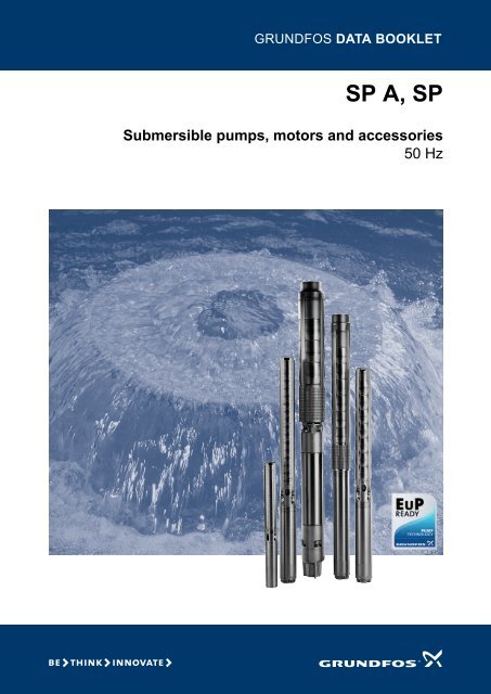
GRUNDFOS DATA BOOKLETSP A, SPSubmersible pumps, motors and accessories50 Hz
SP A, SPTable of contents1. General description 3Performance range 3Applications 4Type key 4Pumped liquids 4Operating conditions 4Curve conditions 4Pump range 5Motor range 5Motor protection and controllers 52. Submersible pumps 6Features and benefits 6Material specification 83. Submersible motors 9Features and benefits 9Shaft seal 11Material specification for MS motors 12Material specification for MMS motors 136. Accessories 77CUE frequency converter 77MP 204 motor protector 79CIU communication interface units 82Connecting pieces 83Cable termination kit with plug 84Cable termination kit, type KM 84Mastik for flat cables 85Cable termination kit, types M0 to M4 85Submersible drop cable 86Cable clips 86Zinc anodes 87Flow sleeves 87SA-SPM control boxes 88Capacitors for MS 402B PSC 88PR 5714 with Pt100 sensor 89CU 220 with Pt1000 sensor 917. Energy consumption 93Energy consumption of submersible pumps 934. Performance curves and technical <strong>data</strong> 14SP 1A 14SP 2A 16SP 3A 18SP 5A 20SP 8A 22SP 14A 24SP 17 26SP 30 31SP 46 36SP 60 41SP 77 46SP 95 51SP 125 56SP 160 61SP 215 665. Electrical <strong>data</strong> 711 x 230 V, submersible motors 713 x 230 V, submersible motors 713 x 230 V, submersible rewindable motors 723 x 400 V, submersible motors 723 x 400 V, submersible industrial motors (60 °C) 733 x 400 V, submersible rewindable motors 743 x 500 V, submersible motors 753 x 500 V, submersible industrial motors 753 x 500 V, submersible rewindable motors 768. Cable sizing 94Cables 94Sizing of cable 96Calculation of the power loss 969. Table of head losses 97Head losses in ordinary water pipes 97Head losses in plastic pipes 9810. Further product documentation 99WebCAPS 99WinCAPS 1002
SP A, SP11. General descriptionPerformance rangep[kPa]6000H[m]600SP50 HzGeneral description400040020002001000100800806006040040SP 1ASP 2ASP 3ASP 5ASP 8ASP 14ASP 17SP 30SP 46SP 60SP 77SP 95SP 125SP160SP 21520020100101 2 4 6 8 10 20 40 60 80 100 200 400Q [m³/h]0.4 0.6 0.8 1 2 4 6 8 10 20 40 60 Q [l/s]TM00 7254 4702EuP readyEffeciency and MEI index for SP pumpsThe SP A, SP pumps areenergy-optimised and comply with theEuP Directive (CommissionRegulation (EC) No 547/2012) whichwill be effective as from 1 January2013. As from this date, all pumps willbe classified/graduated in a newenergy efficiency index (MEI).MEI indexMinimum Efficiency Index (MEI) is the dimensionlessscale unit for hydraulic pump efficiency at bestefficiency point, part load and overload.EU regulations set efficiency requirements to MEI ≥ 0.1as from 1 January 2013 and MEI ≥ 0.4 as from 1January 2015. An indicative benchmark for thebest-performing water pumps available on the marketin 2012 is MEI ≥ 0.70.Pump type Pump size Efficiency [%] MEISP 1A-9 4" 39 ≥ 0.80SP 2A-9 4" 50 ≥ 0.80SP 3A-9 4" 58 ≥ 0.80SP 5A-12 4" 60 ≥ 0.56SP 8A-10 4" 61 ≥ 0.14SP 11A-9 4" 60 ≥ 0.10SP 14A-10 4" 61 ≥ 0.10SP 17-9 6" 74 ≥ 0.76SP 30-9 6" 75 ≥ 0.50SP 46-9 6" 76 ≥ 0.50SP 60-9 6" 77 ≥ 0.60SP 77-9 8" 78 ≥ 0.44SP 95-9 8" 79 ≥ 0.50SP 125-9 10" 79 ≥ 0.37SP 160-9 10" 80 ≥ 0.39SP 215-9 10" 83 ≥ 0.46For more information about the new energy directive and MEI indexplease visit:energy.<strong>grundfos</strong>.comeuropump.eu/efficiencycharts3
1SP A, SPGeneral descriptionApplicationsThe SP A and SP pumps are suitable for the followingapplications:• raw-water supply• irrigation• groundwater lowering• pressure boosting• fountain applications• mining applications• off-shore applications.Type keyExample SP 95 - 5 - A B NType range (SP A, SP)Rated flow rate in m 3 /hNumber of impellersFirst reduced-diameter impeller (A, B or C)Second reduced-diameter impeller (A, B or C)Stainless-steel parts of material= EN 1.4301N = EN 1.4401R = EN 1.4539Pumped liquidsClean, thin, non-aggressive liquids without solidparticles or fibres.The special SP A-N and SP-N versions made ofstainless steel to EN 1.4401 and SP A-R and SP-Rversions made of stainless steel to EN 1.4539 areavailable for applications involving aggressive liquids.Operating conditionsMaximum liquid temperatureGrundfos motorFlow velocitypast motor[m/s]Max. liquidtemperature[°C]MS 4" 0.15 40MS 6000 0.15 30MS 4" industrial versions 0.15 60MS 6000 industrial versions 0.15 60MMS 6" with PVC in the0.15 25windings0.50 30MMS 6" with PE/PA in the 0.15 45windings0.50 50MMS 8", 10", 12" rewindable 0.15 25with PVC in the windings0.50 30MMS 8", 10", 12" rewindable 0.15 40with PE/PA in the windings 0.50 45Operating pressureGrundfos motorMS 402MS 4000 and 6"MMS 6", 8", 10", 12" rewindableCurve conditionsMaximum operating pressure1.5 MPa (15 bar)6 MPa (60 bar)The conditions below apply to the curves on pages 14to 70.General conditions• Curve tolerances according to ISO 9906, 2012Grade 3B.• The performance curves show pump performanceat actual speed, cf. standard motor range.Approximate motor speeds:4" motors: n = 2870 min -16" motors: n = 2870 min -18" to 12" motors: n = 2900 min -1 .• The measurements were made with airless water ata temperature of 20 °C. The curves apply to akinematic viscosity of 1 mm 2 /s (1 cSt). Whenpumping liquids with a density higher than that ofwater, use motors with correspondingly higheroutputs.• The bold curves indicate the recommendedperformance range.• The performance curves are inclusive of possiblelosses such as non-return valve loss.SP A, SP curves• Q/H: The curves are inclusive of valve and inletlosses at the actual speed.Operation without non-return valve will increase theactual head at rated performance by 0.5 to 1.0 m.• NPSH: The curve is inclusive of pressure loss in thesuction interconnector and shows required inletpressure.• Power curve: P2 shows the pump power input ofeach stage for the individual pump size when thepump is running at the rated speed.• Efficiency curve: Eta shows pump stage efficiency.If Eta for the actual pump size is needed, pleaseconsult www.<strong>grundfos</strong>.com (WebCAPS).Note: For MMS 6", 37 kW, MMS 8", 110 kW, and MMS 10", 170 kW,the maximum liquid temperature is 5 °C lower than the values stated inthe table above. For MMS 10", 190 kW, the temperature is 10 °C lower.4
SP A, SP1Pump rangeType SP 1A SP 2A SP 3A SP 5A SP 8A SP 14A SP 17 SP 30 SP 46 SP 60 SP 77 SP 95 SP 125 SP 160 SP 215Steel:EN 1.4301● ● ● ● ● ● ● ● ● ● ● ● ● ● ●AISI 304Steel: (N)EN 1.4401● ● ● ● ● ● ● ● ● ● ● ● ●AISI 316Steel: (R)EN 1.4539AISI 904L● ● ● ● ● ● ● ● ● ● ●Connection* Rp 1 1/4Flange connection:Grundfos flangeRp 1 1/4(R 1 1/4)Rp 1 1/4Rp 1 1/2(R 1 1/2)Rp 2(R 2)* Figures in brackets ( ) indicate connection for pumps with sleeve.Rp 2Rp 2 1/2(R 3)Rp 3(R 3)Rp 3Rp 4(R 4)Rp 3Rp 4Rp 5 Rp 5 Rp 6 Rp 6 Rp 65" 5" 6" 6" 6"General descriptionMotor rangeMotor output[kW]0.37 0.55 0.75 1.1 1.5 2.2 3.0 3.7 4.0 5.5 7.5 9.2 11 13 15 18.5 22 26 30 37 45 55 63 75 92 110 132 147 170 190 220 250MS 402 ● ● ● ● ● ●MS 4000 (R) ● ● ● ● ● ● ● ● ●MS 4000l (R) ● ● ● ● ●MS 6000 (R) ● ● ● ● ● ● ● ● ● ●MS 6000l (R) ● ● ● ● ● ● ● ●MMS 6 (N, R) ● ● ● ● ● ● ● ● ● ● ● ● ●MMS 8000 (N, R) ● ● ● ● ● ● ● ● ● ●MMS 10000 (N, R) ● ● ● ● ● ● ●MMS 12000 (N) ● ● ● ● ●Direct-on-line starting is recommended up to 75 kW.Soft starter or autotransformer is recommended above 75 kW.Motors with star-delta starting are available from 5.5 kW.MS 4000(I) and MS 6000(I) are available with a built-in temperature transmitter (Tempcon).Motor protection and controllersMotor output[kW]0.37 0.55 0.75 1.1 1.5 2.2 3.0 3.7 4.0 5.5 7.5 9.2 11 13 15 18.5 22 26 30 37 45 55 63 75 92 110 132 147 170 190 220 250CUE ● ● ● ● ● ● ● ● ● ● ● ● ● ● ● ● ● ● ● ● ● ● ● ● ● ● ● ● ● ● ●MP 204 ● ● ● ● ● ● ● ● ● ● ● ● ● ● ● ● ● ● ● ● ● ● ● ● ● ● ● ● ● ● ● ●IO 112 ● ● ● ● ● ● ● ● ● ● ● ● ● ● ● ● ● ● ● ● ● ● ● ● ● ● ● ● ● ● ● ●PR 5714 ● ● ● ● ● ● ● ● ● ● ● ● ● ● ● ● ● ● ● ● ● ● ● ● ● ● ● ● ● ● ● ●CU 220 ● ● ● ● ● ● ● ● ● ● ● ● ● ● ● ● ● ● ● ● ● ● ● ● ● ● ● ● ● ● ● ●Pt100 ● ● ● ● ● ● ● ● ● ● ● ● ● ● ● ● ● ● ● ● ● ● ● ● ● ● ● ● ● ● ● ●Pt1000 ● ● ● ● ● ● ● ● ● ● ● ● ● ● ● ● ● ● ● ● ● ● ● ● ● ● ● ● ● ● ● ●Zinc anode ● ● ● ● ● ● ● ● ● ● ● ● ● ● ● ● ● ● ● ● ● ● ● ● ● ● ● ● ● ● ● ●Flow sleeve ● ● ● ● ● ● ● ● ● ● ● ● ● ● ● ● ● ● ● ● ● ● ● ● ● ● ● ● ● ● ● ●SA-SPM ● ● ● ● ● ●R100 ● ● ● ● ● ● ● ● ● ● ● ● ● ● ● ● ● ● ● ● ● ● ● ● ● ● ● ● ● ● ● ●CIU ● ● ● ● ● ● ● ● ● ● ● ● ● ● ● ● ● ● ● ● ● ● ● ● ● ● ● ● ● ● ● ●Motor protection of single-phase motors, see section 5. Electrical <strong>data</strong>, page 71.5
2SP A, SPSubmersible pumps2. Submersible pumpsFeatures and benefitsA wide pump rangeGrundfos offers energy-efficient submersible pumpsranging from 1 to 280 m 3 /h. The pump range consistsof many pump sizes, and each pump size is availablewith an optional number of stages to match any dutypoint.High pump efficiencyOften pump efficiency is a neglected factor comparedto the price. However, the observant user will noticethat price variations are without importance to watersupply economics compared to the importance ofpump and motor efficiencies.ExampleWhen pumping 200 m 3 /h at a head of 100 m for aperiod of 10 years, EUR 60,000 will be saved if apump/motor having a 10 % higher efficiency is chosenand the price is EUR 0.10 per kWh.Eta[%]1009080706050403020100Fig. 11A50 Hz3A 5A 8A 14A 17 30 60 95 1602A46 77 125 2150,1 0 15 10 50 100 500Q [m³/h]Pump/motor efficiencies in relation to flowTM00 7255 1898Material and pumped liquidsGrundfos offers a complete range of pumps andmotors which, as standard, are made completely ofstainless steel to EN 1.4301 (AISI 304). This ensuresgood wear resistance and a reduced risk of corrosionwhen pumping ordinary cold water with a minorchloride content.A pump range made of upgraded stainless steel isavailable for more aggressive liquids:SP N: EN 1.4401 (AISI 316)SP R: EN 1.4539 (AISI 904L).Alternatively, a complete range of zinc anodes forcathodic protection is available. See page 87. Forexample, this may be advisable for seawaterapplications.For slightly polluted liquids containing for example oil,Grundfos offers a complete range of stainless-steelSP NE pumps to EN 1.4401 (AISI 316) with all rubberparts made of FKM.Fig. 2Various SP pumpsGr6389 2806Low installation costsStainless steel means low weight facilitating thehandling of pumps and resulting in low equipmentcosts and reduced installation and service time.6
SP A, SP2Bearings with sand channelsAll bearings are water-lubricated and have a squaredshape enabling sand particles, if any, to leave the pumptogether with the pumped liquid.Inlet strainerThe inlet strainer prevents particles over a certain sizefrom entering the pump.Fig. 3BearingTM00 7301 1096TM00 7302 1096Submersible pumpsFig. 4Inlet strainerNon-return valveAll pumps have a reliable non-return valve in the valvecasing preventing backflow in connection with pumpstoppage.Furthermore, the short closing time of the non-returnvalve means that the risk of destructive water hammer isreduced to a minimum.The valve casing is designed for optimum hydraulicproperties to minimise the pressure loss across the valveand thus to contribute to the high efficiency of the pump.Valve flapTM01 2499 1798Fig. 5Non-return valvePriming screwAll Grundfos pumps with radial impellers are fitted with apriming screw. Consequently, dry running is preventedbecause the priming screw will ensure that the pumpbearings are always lubricated.SP pumps with semi-axial impellers require no primingscrew. The pumps are primed automatically.It applies to all pump types, however, that neither pumpnor motor will be protected against dry running if thewater table is lowered to a level below the pump inlet.TM00 7304 1096Fig. 6Priming screwStop ringThe stop ring prevents damage to the pump duringtransport and in case of up-thrust in connection withstart-up.The stop ring, which is designed as a thrust bearing,limits axial movements of the pump shaft.The stationary part of the stop ring (A) is secured in theupper chamber.The rotating part (B) is fitted above the split cone (C).ABCTM01 3327 3898Fig. 7Stop ring (rotating and stationary parts) and splitcone7
2SP A, SPSubmersible pumpsMaterial specificationPos. ComponentMaterial1 Valve casing Stainless steel1d O-ring NBR2 Valve cup Stainless steel3 Valve seat3a3bLower valveseat retainerUpper valveseat retainerStandard/N-version:NBRR-version:FKMStandard N-version R-version1.4301/3041.4301/304Stainless steel 1.4308Stainless steel4 Top chamber Stainless steel6 Upper bearingStainless steel/NBR7 Neck ring NBR/PPS8 Bearing NBR8aWasher forstop ringCarbon/graphiteHY22 in PTFEmass8b Stop ring Stainless steel9 Chamber Stainless steel11 Split cone nut Stainless steel11cNut for stopringStainless steel12 Split cone Stainless steel13 Impeller Stainless steel14SuctioninterconnectorCast stainlesssteel15 Strainer Stainless steel16 Shaft complete Stainless steel17 Strap Stainless steel18 Cable guard Stainless steel19 Nut for strap Stainless steel39Spring forvalve cupStainless steel70 Valve guide Stainless steel71 Washer Stainless steel72 Wear ring Stainless steel1.4301/3041.4301/3041.4401/3041.4401/3161.4301/3041.4301/3041.4401/3161.4301/3041.4301/3041.43081.4301/3041.4057/4311.4301/3041.4301/3041.4301/3041.4301/3041.4301/3041.4401/3161.4301/304EN/AISI1.4401/3161.4401/3161.4408/3161.4401/3161.4401/3161.4401/3161.4401/3161.4401/3161.4401/3161.4401/3161.4401/3161.4401/3161.4408/3161.4401/3161.4460/3291.4401/3161.4401/3161.4401/3161.4401/3161.4401/3161.4401/3161.4401/3161.4539/904L1.4539/904L1.45171.4539/904L1.4539/904L1.4539/904L1.4539/904L1.4539/904L1.4539/904L1.4539/904L1.4539/904L1.4539/904L1.45171.4539/904L1.4462/904L1.4539/904L1.4539/904L1.4539/904L1.4462/SAF 22051.4539/904L1.4539/904L1.4539/904L8a11c167177119Fig. 8 SP 771703923b31d3a68b 478 9137278 91112181514TM01 2359 23018
SP A, SP33. Submersible motorsFeatures and benefitsA complete motor rangeGrundfos offers a complete range of submersiblemotors in different voltages:Submersible motors, MS• 4" motors, single-phase up to 2.2 kW:– 2-wire– 3-wire– PSC (permanent split capacitor)• 4" motors, three-phase up to 7.5 kW• 4" industrial motors, three-phase up to 5.5 kW• 6" motors, three-phase from 5.5 to 30 kW• 6" industrial motors, three-phase up to 22 kW.Submersible, rewindable motors, MMS• 6" motors, three-phase from 3.7 to 37 kW• 8" motors, three-phase from 22 to 110 kW• 10" motors, three-phase from 75 to 190 kW• 12" motors, three-phase from 147 to 250 kW.High motor efficiencyWithin the area of high motor efficiency, Grundfos is amarket leader.Rewindable motorsThe 2-pole Grundfos MMS submersible motors are alleasy to rewind. The windings of the stator are made ofa special water-proof wire of pure electrolytic coppersheathed with special non-hydroscopic thermoplasticmaterial. The fine dielectric properties of this materialallow direct contact between the windings and theliquid for efficient cooling of the windings.Industrial motorsFor heavy-duty applications, Grundfos offers acomplete motor range of industrial motors with up to5 % higher efficiency than that of Grundfos' standardmotors. The industrial motors are available in sizes2.2 to 22 kW. The cooling of the motor is very efficientdue to the large motor surface. The efficient coolingmakes it possible to increase the liquid temperature to60 °C at a minimum flow of 0.15 m/s past the motor.The industrial motors are for customers who value lowoperating costs and long life higher than price.Grundfos industrial motors are developed for difficultoperating conditions. These motors will stand a higherthermal load than standard motors and thus have alonger life when subjected to high load. This applieswhether the high load is caused by bad power supply,hot water, bad cooling conditions, high pump load, etc.Please note that heavy-duty motors are longer thanmotors for standard conditions.Fig. 9MS motorsFig. 10 MMS motorsTM00 7305 1096TM01 7873 4799 - GrA4575 3908Submersible motors9
3SP A, SPSubmersible motorsOvertemperature protectionProtecting the motor against too high motortemperature is the simplest and cheapest way ofavoiding that the motor life is reduced.Accessories for protection against overtemperatureare available for both Grundfos MS and MMSsubmersible motors. When the temperature becomestoo high, the protection device will cut out, anddamage to the pump and motor will be avoided.MSThe Grundfos MS submersible motors, except MS 402,are available with built-in Tempcon temperature sensorfor protection against overtemperature. By means ofthis sensor it is possible to read out and/or monitor themotor temperature via an MP 204 motor protector.MMSThe Grundfos MMS submersible motors are notavailable with built-in Tempcon temperature sensor.For these motors, we offer Pt100 and Pt1000 sensorsfor temperature monitoring. Together with either anMP 204 motor protector, a PR 5714 relay or a CU 220control unit, the sensor ensures that the operatingconditions are not exceeded.Protection against upthrustIn case of a very low counter pressure in connectionwith start-up, there is a risk that the entire chamberstack may rise. This is called upthrust. Upthrust maydamage both pump and motor. Therefore, bothGrundfos pumps and motors are protected againstupthrust as standard, preventing upthrust fromoccurring in the critical start-up phase. The protectionconsists of either a built-in stop ring or hydraulicbalancing.Built-in cooling chambersIn all Grundfos MS submersible motors, an efficientcooling is ensured by cooling chambers at the top andat the bottom of the motor and by an internalcirculation of motor liquid. See fig. 11. As long as therequired flow velocity past the motor is maintained(see section Operating conditions, page 4), cooling ofthe motor will be efficient.TM00 5698 0996Fig. 11 MS 400010
SP A, SP3Lightning protectionThe smallest Grundfos submersible motors, i.e.MS 402, are all insulated in order to minimise the riskof motor burnout caused by stroke of lightning.Reduced risk of short-circuitThe embedded stator winding in the Grundfos MSsubmersible motor is hermetically enclosed instainless steel. The result is high mechanical stabilityand optimum cooling. Also, this eliminates the risk ofshort-circuit of the windings caused by condensedwater.Submersible motorsShaft sealMS 402The shaft seal is of the lip seal type characterised bylow friction against the rotor shaft.The choice of rubber offers good wear resistance,good elasticity and resistance to particles. The rubbermaterial is approved for use in drinking water.MS 4000, MS 6000The material is ceramic/tungsten carbide providingoptimum sealing, optimum wear resistance and longlife.The spring-loaded shaft seal is designed with a largesurface and a sand shield. The result is a minimumexchange of pumped liquid and motor liquid and nopenetration of particles. Motors, version R, have aSiC/SiC shaft seal according to DIN 24960. Othercombinations are available on request.MMS rewindable motorsThe standard shaft seal is a ceramic/carbonmechanical shaft seal. The shaft seal is replaceable.The material provides good wear resistance andresistance to particles.Together with the shaft seal housing, the sand shieldforms a labyrinth seal, which during normal operatingconditions prevents penetration of sand particles intothe shaft seal.On request, motors can be supplied with a SiC/SiCseal according to DIN 24960.Fig. 12 Shaft seal, MS 4000TM00 7306 210011
3SP A, SPSubmersible motorsMaterial specification for MSmotorsMS 402 and MS 4000 submersible motorsPos. Component MS 402MS 4000MS 60001 Shaft EN 1.4057 EN 1.40572 Shaft seal NBRCeramic/tungstencarbide3 Motor sleeve EN 1.4301 EN 1.43014 Motor end shield EN 1.43015 Radial bearing CeramicCeramic/tungstencarbide6 Axial bearing Ceramic/carbon Ceramic/carbonRubber parts NBR NBRR-version motor1253Pos. ComponentMS 4000MS 60001 Shaft EN 1.44622 Shaft seal NBR/ceramic3 Motor sleeve EN 1.45394 Motor end shield EN 1.45395 Radial bearingCeramic/tungstencarbide6 Thrust bearing Ceramic/carbonRubber partsNBR564TM00 7865 2196Fig. 13 MS 400012
SP A, SP3Material specification for MMSmotorsSubmersible, rewindable motorsPos. Component Material EN202 Shaft Steel 1.0533202a Shaft ends Stainless steel 1.4460203/206Thrust bearingStationary/rotating part6"3.7 to 15 kW Hardenedsteel/EPDM12"6"18.5 to 37 kW Ceramic/carbon8" to 10"6" to 10" Carbon204 Bearing bushStainless12"steel/NBR205 Bearing housing, upper Cast iron EN-JL1040212 Diaphragm CR213 Motor end shield Cast iron EN-JL1040218 Motor sleeve Stainless steel 1.4301220 Motor cable EPDM226 Shaft sealCeramic/carbon235 Intermediate housing Cast iron EN-JL1040236 Bearing housing, lower Cast iron EN-JL1040N- and R-versions of MMS motors226202a220204205235202218Submersible motorsVersionPos. Component MaterialNREN EN202 Shaft Steel 1.0533 1.0533202a Shaft ends Stainless steel 1.4460 1.4462203/206204Thrust bearingStationary/rotating part:• 6" (3.7 to 15 kW)• 12"Thrust bearingStationary/rotating part:• 6" (18.5 to 37 kW)• 8" to 10"Bearing bush• 6" to 10"Bearing bush• 12"Hardenedsteel/EPDMCeramic/carbonCarbonStainlesssteel/NBR205 Bearing housing, upper Stainless steel 1.4401 1.4539212 Diaphragm CR213 Motor end shield Stainless steel 1.4401 1.4539218 Motor sleeve Stainless steel 1.4401 1.4539220 Motor cable EPDM226 Shaft sealCeramic/carbon235 Intermediate housing Stainless steel 1.4401 1.4539236 Bearing housing, lower Stainless steel 1.4401 1.4539202aFig. 14 MMS 10000236206203213212TM01 4985 040413
Performance curves and technical <strong>data</strong>SP A, SP4SP 1A4. Performance curves and technical <strong>data</strong>SP 1APerformance curvesp[kPa]H[m]320300-57SP 1A50 HzISO 9906:2012 Grade 3B2800280-502602400240-422202000200-361801600160-281401200120-21100-1880080-1460-94004020000.0 0.2 0.4 0.6 0.8 1.0 1.2 1.4 Q [m³/h]P2[hp]0.0 0.1 0.2 0.3 0.4 Q [l/s]P2[kW]Eta0.04Eta[%]400.040.020.000.030.02P20.010.000.0 0.2 0.4 0.6 0.8 1.0 1.2 1.4 Q [m³/h]3020100TM00 7271 4702Explanation of efficiency curve, please see Curve conditions, page 4.14
SP A, SPPerformance curves and technical <strong>data</strong>4Dimensions and weightsSP 1A101Rp 1 1/4Pump typeTypeMotorPower[kW]C1x230VDimensions [mm]B3x230V3x400V1x230VA3x230V3x400VNet weight[kg]1x230V3x230V3x400VB C95ATM00 0955 1196SP 1A-9 MS 402 0.37 344 256 226 600 570 11 9SP 1A-14 MS 402 0.37 449 256 226 705 675 12 10SP 1A-18 MS 402 0.55 533 291 241 824 774 14 12SP 1A-21 MS 402 0.55 596 291 241 887 837 14 12SP 1A-28 MS 402 0.75 743 306 276 1049 1019 16 15SP 1A-36 MS 402 1.1 956 346 306 1302 1262 25 23SP 1A-42 MS 402 1.1 1082 346 306 1428 1388 27 25SP 1A-50 MS 402 1.5 1250 346 346 1596 1596 30 29SP 1A-57 MS 402 1.5 1397 346 346 1743 1743 32 32101 mm = Maximum diameter ofpump inclusive of cable guardand motor.15
Performance curves and technical <strong>data</strong>SP A, SP4SP 2ASP 2APerformance curvesp[kPa]5600H[m]560-90SP 2A50 HzISO 9906:2012 Grade 3B5204800480-754404000400-653603200320-55-482802400240-40200-331600160-28-23120-1880080-13-940-6000.0 0.4 0.8 1.2 1.6 2.0 2.4 2.8 Q [m³/h]P2[hp]0.060.040.0 0.2 0.4 0.6 0.8P2Q [l/s][kW]0.05Eta0.04P20.03Eta[%]5040300.020.000.020.010.000.0 0.4 0.8 1.2 1.6 2.0 2.4 2.8 Q [m³/h]20100TM00 7272 4702Explanation of efficiency curve, please see Curve conditions, page 4.16
SP A, SPPerformance curves and technical <strong>data</strong>4Dimensions and weightsSP 2A101Rp 1 1/4Pump typeTypeMotorPower[kW]C1x230VDimensions [mm]B3x230V3x400V1x230VA3x230V3x400VNet weight[kg]1x230V3x230V3x400VB C95ATM00 0955 1196SP 2A-6 MS 402 0.37 281 256 226 537 507 10 9SP 2A-9 MS 402 0.37 344 256 226 600 570 11 9SP 2A-13 MS 402 0.55 428 291 241 719 669 13 11SP 2A-18 MS 402 0.75 533 306 276 839 809 15 13SP 2A-23 MS 402 1.1 638 346 306 984 944 17 16SP 2A-28 MS 402 1.5 743 346 346 1089 1089 19 18SP 2A-33 MS 402 1.5 844 346 346 1190 1190 20 19SP 2A-40 MS 4000 2.2 1040 573 1613 37SP 2A-40 MS 402 2.2 1040 346 1386 27SP 2A-48 MS 4000 2.2 1208 573 1781 39SP 2A-48 MS 402 2.2 1208 346 1554 30SP 2A-55 MS 4000 3.0 1355 493 1848 38SP 2A-65 MS 4000 3.0 1565 493 2058 41SP 2A-75 MS 4000 4.0 1954 573 2527 57SP 2A-90 MS 4000 4.0 2269 573 2842 64101 mm = Maximum diameter ofpump inclusive of cable guardand motor.SP 2A-75 and SP 2A-90 aremounted in sleeve for R 1 1/4connection and with a maximumdiameter of 108 mm.17
Performance curves and technical <strong>data</strong>SP A, SP4SP 3ASP 3APerformance curvesp[kPa]3600H[m]360-60SP 3A50 HzISO 9906:2012 Grade 3B3200320-522800280-452400240-392000200-33-291600160-25-221200120-18-1580080-12-940040-6000.0 0.4 0.8 1.2 1.6 2.0 2.4 2.8 3.2 3.6 4.0 Q [m³/h]P2[hp]0.160.0 0.2 0.4 0.6 0.8 1.0 1.2 Q [l/s]P2[kW]Eta0.12Eta[%]600.120.09450.080.040.000.06P20.030.000.0 0.4 0.8 1.2 1.6 2.0 2.4 2.8 3.2 3.6 4.0 Q [m³/h]30150TM00 7273 4702Explanation of efficiency curve, please see Curve conditions, page 4.18
SP A, SPPerformance curves and technical <strong>data</strong>4Dimensions and weightsSP 3AB C10195Rp 1 1/4A101 mm = Maximum diameter ofpump inclusive of cable guardand motor.TM00 0955 1196Pump typeTypeMotorPower[kW]C1x230VDimensions [mm]B3x230V3x400V1x230VA3x230V3x400VNet weight[kg]1x230V3x230V3x400VSP 3A-6* MS 402 0.37 281 256 226 537 507 10 9SP 3A-6N MS 4000R 2.2 326 573 899 26SP 3A-6N MS 4000R 0.75 326 398 724 18SP 3A-9* MS 402 0.55 344 291 241 635 585 12 10SP 3A-9N MS 4000R 2.2 389 573 962 27SP 3A-9N MS 4000R 0.75 389 398 787 19SP 3A-12* MS 402 0.75 407 306 276 713 683 13 12SP 3A-12N MS 4000R 2.2 452 573 1025 28SP 3A-12N MS 4000R 0.75 452 398 850 20SP 3A-15* MS 402 1.1 470 346 306 816 776 16 14SP 3A-15N MS 4000R 2.2 515 573 1088 29SP 3A-15N MS 4000R 1.1 515 413 928 22SP 3A-18* MS 402 1.1 533 346 306 879 839 16 15SP 3A-18N MS 4000R 2.2 578 573 1151 30SP 3A-18N MS 4000R 1.1 578 413 991 23SP 3A-22* MS 402 1.5 617 346 346 963 963 18 17SP 3A-22N MS 4000R 2.2 662 573 1235 31SP 3A-22N MS 4000R 1.5 662 413 1075 24SP 3A-25* MS 402 1.5 680 346 346 1026 1026 18 18SP 3A-25N MS 4000R 2.2 725 573 1298 32SP 3A-25N MS 4000R 1.5 725 413 1138 25SP 3A-29* MS 4000 2.2 764 573 1337 29SP 3A-29* MS 402 2.2 764 346 1110 20SP 3A-29N MS 4000R 2.2 809 573 453 1382 1262 33 28SP 3A-33* MS 4000 2.2 848 573 1421 30SP 3A-33* MS 402 2.2 848 346 1194 21SP 3A-33N MS 4000R 2.2 893 573 453 1466 1346 34 29SP 3A-39 MS 4000 3.0 1019 493 1512 32SP 3A-45 MS 4000 3.0 1145 493 1638 34SP 3A-52 MS 4000 4.0 1292 573 1865 41SP 3A-60 MS 4000 4.0 1460 573 2033 43* Pumps with spline shaft are only available in stainless steel EN 1.4301/AISI 304.Note: All other pumps listed above are also available in N- and R-versions. See page 5.19
Performance curves and technical <strong>data</strong>SP A, SP4SP 5ASP 5APerformance curvesp[kPa]5600H[m]560-85SP 5A50 HzISO 9906:2012 Grade 3B5204800480-754404000400-603603200320-52280-442400240-38200-331600160-25-21120-1780080-1240-8-6-4000.0 0.8 1.6 2.4 3.2 4.0 4.8 5.6 6.4 Q [m³/h]P2[hp]0.160.0 0.4 0.8 1.2 1.6 Q [l/s]P2[kW]Eta0.12Eta[%]600.080.000.08P20.040.000.0 0.8 1.6 2.4 3.2 4.0 4.8 5.6 6.4 Q [m³/h]40200TM00 7274 4702Explanation of efficiency curve, please see Curve conditions, page 4.20
SP A, SPPerformance curves and technical <strong>data</strong>4Dimensions and weightsSP 5AB CEDRp 1 1/2ASP 5A-75 and SP 5A-85 aremounted in sleeve for R 1 1/2connection.TM00 0956 1196Pump typeTypeMotorPower[kW]C1x230VBDimensions [mm]3x230V3x400VA1x230V3x230V3x400VDENet weight[kg]1x230V3x230V3x400VSP 5A-4* MS 402 0.37 240 256 226 496 466 95 101 10 8SP 5A-4N MS 4000R 2.2 284 573 857 95 101 25SP 5A-4N MS 4000R 0.75 284 398 682 95 101 17SP 5A-6* MS 402 0.55 282 291 241 573 523 95 101 11 10SP 5A-6N MS 4000R 2.2 326 573 899 95 101 26SP 5A-6N MS 4000R 0.75 326 398 724 95 101 18SP 5A-8* MS 402 0.75 324 306 276 630 600 95 101 13 11SP 5A-8N MS 4000R 2.2 368 573 941 95 101 27SP 5A-8N MS 4000R 0.75 368 398 766 95 101 19SP 5A-12* MS 402 1.1 408 346 306 754 714 95 101 15 13SP 5A-12N MS 4000R 2.2 452 573 1025 95 101 28SP 5A-12N MS 4000R 1.1 452 413 865 95 101 21SP 5A-17* MS 402 1.5 513 346 346 859 859 95 101 17 16SP 5A-17N MS 4000R 2.2 557 573 1130 95 101 29SP 5A-17N MS 4000R 1.5 557 413 970 95 101 22SP 5A-21* MS 4000 2.2 597 573 1170 95 101 27SP 5A-21* MS 402 2.2 597 346 943 95 101 18SP 5A-21N MS 4000R 2.2 641 573 453 1214 1094 95 101 30 25SP 5A-25* MS 4000 2.2 681 573 1254 95 101 28SP 5A-25* MS 402 2.2 681 346 1027 95 101 19SP 5A-25N MS 4000R 2.2 725 573 453 1298 1178 95 101 32 27SP 5A-33* MS 4000 3.0 849 493 1342 95 101 26SP 5A-33N MS 4000R 3.0 893 493 1386 95 101 30SP 5A-38 MS 4000 4.0 998 573 1571 95 101 36SP 5A-44 MS 4000 4.0 1124 573 1697 95 101 38SP 5A-52 MS 4000 5.5 1292 673 1965 95 101 46SP 5A-60 MS 4000 5.5 1460 673 2133 95 101 48SP 5A-52 MS 6000 5.5 1354 541 1895 138 138 60SP 5A-60 MS 6000 5.5 1522 541 2063 138 138 63SP 5A-75 MS 6000 7.5 2146 571 2717 138 140 86SP 5A-85 MS 6000 7.5 2356 571 2927 138 140 92E = Maximum diameter of pump inclusive of cable guard and motor.* Pumps with spline shaft are only available in stainless steel EN 1.4301/AISI 304.Note: All other pumps listed above are also available in N- and R-versions. See page 5.Pumps mounted in sleeve are only available in standard and N-versions.21
Performance curves and technical <strong>data</strong>SP A, SP4SP 8ASP 8APerformance curvesp[kPa]6400H[m]700650-110SP 8A50 HzISO 9906:2012 Grade 3B600-1005600550-914800500-82450-734000400-66350-583200300-50-442400250-37200-30160080015010050-25-21-18-15-12-10-7-5000 1 2 3 4 5 6 7 8 9 10 Q [m³/h]P2[hp]0.30.0 0.5 1.0 1.5 2.0 2.5 3.0 Q [l/s]P2[kW]0.24EtaEta[%]600.20.16P2400.10.00.080.000 1 2 3 4 5 6 7 8 9 10 Q [m³/h]200TM00 7275 4702Explanation of efficiency curve, please see Curve conditions, page 4.22
SP A, SPPerformance curves and technical <strong>data</strong>4Dimensions and weightsSP 8AB CEDRp 2ASP 8A-58(N) to SP 8A-110(N) are mounted insleeve for R 2 connection.TM00 0957 1196Pump typeTypeMotorPower[kW]CB1x230V 3x230V3x400VDimensions [mm]A1x230V3x230V3x400VDENet weight[kg]1x230V 3x230V3x400VSP 8A-5 MS 402 0.75 409 306 276 715 685 95 101 15 13SP 8A-5 MS 4000 2.2 409 573 982 95 101 27SP 8A-5 MS 4000R 0.75 409 398 807 95 101 19SP 8A-7 MS 402 1.1 493 346 306 839 799 95 101 17 16SP 8A-7 MS 4000 2.2 493 573 1066 95 101 28SP 8A-7 MS 4000R 1.1 493 413 906 95 101 21SP 8A-10 MS 402 1.5 619 346 346 965 965 95 101 19 19SP 8A-10 MS 4000 2.2 619 573 1192 95 101 30SP 8A-10 MS 4000R 1.5 619 413 1032 95 101 23SP 8A-12 MS 4000 2.2 703 573 1276 95 101 30SP 8A-12 MS 402 2.2 703 346 1049 95 101 21SP 8A-12 MS 4000 2.2 703 573 453 1276 1156 95 101 30 25SP 8A-15 MS 4000 2.2 829 573 1402 95 101 32SP 8A-15 MS 402 2.2 829 346 1175 95 101 23SP 8A-15 MS 4000 2.2 829 573 453 1402 1282 95 101 32 27SP 8A-18 MS 4000 3.0 955 493 1448 95 101 29SP 8A-21 MS 4000 4.0 1081 573 1654 95 101 35SP 8A-25 MS 4000 4.0 1249 573 1822 95 101 37SP 8A-30 MS 4000 5.5 1459 673 2132 95 101 45SP 8A-37 MS 4000 5.5 1753 673 2426 95 101 49SP 8A-30 MS 6000 5.5 1521 541 2062 138 138 56SP 8A-37 MS 6000 5.5 1521 541 2356 138 138 60SP 8A-44 MS 4000 7.5 1815 773 2824 95 101 60SP 8A-44 MS 6000 7.5 2109 571 2680 138 138 66SP 8A-50 MS 4000 7.5 2303 773 3076 95 101 64SP 8A-50 MS 6000 7.5 2361 571 2932 138 138 70SP 8A-58 MS 6000 9.2 3013 601 3614 138 140 104SP 8A-66 MS 6000 11.0 3349 631 3980 138 140 114SP 8A-73 MS 6000 11.0 3643 631 4274 138 140 120SP 8A-82 MS 6000 13.0 4021 661 4682 138 140 131SP 8A-91 MS 6000 15.0 4399 696 5095 138 140 143SP 8A-100 MS 6000 15.0 4777 696 5473 138 140 150SP 8A-110 MS 6000 18.5 5197 751 5948 138 140 164E = Maximum diameter of pump inclusive of cable guard and motor.Note: The pump types above are also available in N- and R-versions. See page 5.Pumps mounted in sleeve are only available in standard and N-versions.23
Performance curves and technical <strong>data</strong>SP A, SP4SP 14ASP 14APerformance curvesp[kPa]1600H[m]170160-25SP 14A50 HzISO 9906:2012 Grade 3B15014001401301200120-18110100010090-138008070-106006050-740040-5302002010000 2 4 6 8 10 12 14 16 18 Q [m³/h]P2[hp]0.40.20.0P2[kW]0.30.20.10.00 1 2 3 4 5 Q [l/s]EtaP20 2 4 6 8 10 12 14 16 18 Q [m³/h]Eta[%]6040200TM00 7276 4702Explanation of efficiency curve, please see Curve conditions, page 4.24
SP A, SPPerformance curves and technical <strong>data</strong>4Dimensions and weightsB CEDRp 2ATM00 0957 1196Pump typeTypeMotorPower[kW]C1x230VBDimensions [mm]3x230V3x400VA1x230V3x230V3x400VDENet weight[kg]1x230V3x230V3x400VSP 14A-5 MS 402 1.5 510 346 346 856 856 95 101 18 17SP 14A-7 MS 4000 2.2 640 573 1213 95 101 29SP 14A-7 MS 402 2.2 640 346 986 95 101 19SP 14A-10 MS 4000 3.0 835 493 1328 95 101 27SP 14A-13 MS 4000 4.0 1030 573 1603 95 101 33SP 14A-18 MS 4000 5.5 1355 673 2028 95 101 41SP 14A-25 MS 4000 7.5 1810 773 2584 95 101 67SP 14A-18 MS 6000 5.5 1417 541 1958 138 138 52SP 14A-25 MS 6000 7.5 1872 571 2443 138 138 60E = Maximum diameter of pump inclusive of cable guard and motor.Note: The pump types above are also available in N-versions. See page 5.SP 14A25
Performance curves and technical <strong>data</strong>SP A, SP4SP 17SP 17Performance curvesp[kPa]1800H[m]190180-17-16SP 1750 HzISO 9906:2012 Grade 3B170-151600160-141400150140-13-121200130120110-11-101000100-990-880080-770-660060-550-440040-3200302010-2-1000 2 4 6 8 10 12 14 16 18 20 Q [m³/h]p[kPa]8060H[m]860 1 2 3 4 5 6 Q [l/s]EtaEta[%]806040200420NPSH0 2 4 6 8 10 12 14 16 18 20 Q [m³/h]40200TM01 8757 4702Explanation of efficiency curve, please see Curve conditions, page 4.26
SP A, SPPerformance curves and technical <strong>data</strong>4p[kPa]H[m]-60SP 17SP 176400650-58-5550 HzISO 9906:2012 Grade 3B600-535600-51550-484800500-45-43400032002400450400350300250200-40-39-38-37-36-35-34-33-32-31-30-29-28-27-26-25-24-23-22-21-20-19-181600150100800500 2 4 6 8 10 12 14 16 18 20 Q [m³/h]p[kPa]8060H[m]860 1 2 3 4 5 6 Q [l/s]EtaEta[%]806040200420NPSH0 2 4 6 8 10 12 14 16 18 20 Q [m³/h]40200TM01 8758 4702Explanation of efficiency curve, please see Curve conditions, page 4.27
Performance curves and technical <strong>data</strong>SP A, SP4SP 17Dimensions and weightsB CEDRp 2 1/2ASP 17-43 to SP 17-60 aremounted in sleeve for R 3connection.The pump types listed are alsoavailable in N- and R-versions.See page 5.Pumps mounted in sleeve areonly available in standard and N-versions.Other types of connection arepossible by means of connectingpieces. See page 83.* Maximum diameter of pumpwith one motor cable.** Maximum diameter of pumpwith two motor cables.TM01 2435 1798Pump typeTypeMotorPower[kW]Dimensions [mm]C B A D E* E**Net weight[kg]Single-phase, 1 x 230 VSP 17-1 MS 402 0.55 324 317 641 95 134 12SP 17-1 MS 4000 2.2 324 577 901 95 134 26SP 17-2 MS 402 1.1 384 387 771 95 134 17SP 17-2 MS 4000 2.2 384 577 961 95 134 27SP 17-3 MS 4000 2.2 444 577 1021 95 134 28SP 17-4 MS 4000 2.2 504 577 1081 95 134 30Three-phase, 3 x 230 V / 3 x 400 VSP 17-1 MS 402 0.55 324 282 606 95 134 11SP 17-1 MS 4000 0.75 324 402 726 95 134 18SP 17-2 MS 402 1.1 384 347 731 95 134 15SP 17-2 MS 4000 1.1 384 417 801 95 134 20SP 17-3 MS 402 2.2 444 387 831 95 134 19SP 17-3 MS 4000 2.2 444 457 901 95 134 23SP 17-4 MS 402 2.2 504 387 891 95 134 21SP 17-4 MS 4000 2.2 504 457 961 95 134 25SP 17-5 MS 4000 3.0 564 497 1061 95 134 27SP 17-6 MS 4000 4.0 624 577 1201 95 134 32SP 17-7 MS 4000 4.0 684 577 1261 95 134 34SP 17-8 MS 4000 5.5 744 677 1421 95 134 40SP 17-9 MS 4000 5.5 804 677 1481 95 134 42SP 17-10 MS 4000 5.5 864 677 1541 95 134 43SP 17-11 MS 4000 7.5 924 777 1701 95 134 50SP 17-12 MS 4000 7.5 984 777 1761 95 134 51SP 17-13 MS 4000 7.5 1044 777 1821 95 134 53SP 17-8 MS 6000 5.5 763 544 1307 143 142 144 49SP 17-9 MS 6000 5.5 823 544 1367 143 142 144 50SP 17-10 MS 6000 5.5 883 544 1427 143 142 144 52SP 17-11 MS 6000 7.5 943 574 1517 143 142 144 56SP 17-12 MS 6000 7.5 1003 574 1577 143 142 144 58SP 17-13 MS 6000 7.5 1063 574 1637 143 142 144 59SP 17-14 MS 6000 9.2 1123 604 1727 143 142 144 66SP 17-15 MS 6000 9.2 1183 604 1787 143 142 144 67SP 17-16 MS 6000 9.2 1243 604 1847 143 142 144 69SP 17-17 MS 6000 9.2 1303 604 1907 143 142 144 70SP 17-18 MS 6000 11 1363 634 1997 143 142 144 75SP 17-19 MS 6000 11 1423 634 2057 143 142 144 76SP 17-20 MS 6000 11 1483 634 2117 143 142 144 77SP 17-21 MS 6000 13 1543 664 2207 143 142 144 82SP 17-22 MS 6000 13 1603 664 2267 143 142 144 83SP 17-23 MS 6000 13 1663 664 2327 143 142 144 84SP 17-24 MS 6000 13 1723 664 2387 143 142 144 86SP 17-25 MS 6000 15 1783 699 2482 143 142 144 91SP 17-26 MS 6000 15 1843 699 2542 143 142 144 92SP 17-27 MS 6000 15 1903 699 2602 143 142 144 94SP 17-28 MS 6000 18.5 1963 754 2717 143 142 144 101SP 17-29 MS 6000 18.5 2023 754 2777 143 142 144 102SP 17-30 MS 6000 18.5 2083 754 2837 143 142 144 103SP 17-31 MS 6000 18.5 2143 754 2897 143 142 144 105SP 17-32 MS 6000 18.5 2203 754 2957 143 142 144 106SP 17-33 MS 6000 18.5 2263 754 3017 143 142 144 108SP 17-34 MS 6000 22 2323 814 3137 143 142 144 115SP 17-35 MS 6000 22 2383 814 3197 143 142 144 116SP 17-36 MS 6000 22 2443 814 3257 143 142 144 118SP 17-37 MS 6000 22 2503 814 3317 143 142 144 119SP 17-38 MS 6000 22 2563 814 3377 143 142 144 120SP 17-39 MS 6000 22 2623 814 3437 143 142 144 122SP 17-40 MS 6000 22 2683 814 3497 143 142 144 123SP 17-43 MS 6000 26 3215 874 4089 143 175 181 164SP 17-45 MS 6000 26 3335 874 4209 143 175 181 167SP 17-48 MS 6000 26 3515 874 4389 143 175 181 173SP 17-51 MS 6000 30 3695 944 4639 143 175 181 186SP 17-53 MS 6000 30 3815 944 4759 143 175 181 189SP 17-55 MMS6 37 3935 1312 5247 144 175 181 234SP 17-58 MMS6 37 4115 1312 5427 144 175 181 240SP 17-60 MMS6 37 4235 1312 5547 144 175 181 24328
SP A, SPPerformance curves and technical <strong>data</strong>4Power curvesSP 17P2[hp]13P2[kW]10.09.6SP 1750 HzISO 9906:2012 Grade 3B9.2128.8-178.4-16118.0-157.6-14107.296.86.4-13-1286.0-115.675.2-104.8-964.4-84.053.6-73.2-642.8-532.42.0-421.6-31.2-210.80.4-100.00 2 4 6 8 10 12 14 16 18 20 Q [m³/h]0 1 2 3 4 5 6 Q [l/s]TM01 8759 470229
Performance curves and technical <strong>data</strong>SP A, SP4SP 17P2[hp]5048P2[kW]3635SP 1750 HzISO 9906:2012 Grade 3B4634443332-60-58424038363431302928272625-55-53-51-48322423-45-4330282624222018161412222120191817161514131211109-40-39-38-37-36-35-34-33-32-31-30-29-28-27-26-25-24-23-22-21-20-19-1810878650 2 4 6 8 10 12 14 16 18 20 Q [m³/h]0 1 2 3 4 5 6 Q [l/s]TM01 8760 470230
SP A, SPPerformance curves and technical <strong>data</strong>4SP 30SP 30Performance curvesp[kPa]1600H[m]170160-15-14SP 3050 HzISO 9906:2012 Grade 3B150-131400140-12130-111200120-101000110100-990-880080-770-660060-550-440040-330-22002010-1000 4 8 12 16 20 24 28 32 36 Q [m³/h]p[kPa]8060H[m]860 2 4 6 8 10 Q [l/s]EtaEta[%]806040200420NPSH0 4 8 12 16 20 24 28 32 36 Q [m³/h]40200TM01 8761 4702Explanation of efficiency curve, please see Curve conditions, page 4.31
Performance curves and technical <strong>data</strong>SP A, SP4SP 30p[kPa]H[m]SP 306400650-5450 HzISO 9906:2012 Grade 3B6000600-525600-495200550-464800500-434400450-39400036003200280024002000400350300250200-34-32-30-28-26-24-22-20-18-16-35-33-31-29-27-25-23-21-19-1716001501200100800500 4 8 12 16 20 24 28 32 36 Q [m³/h]p[kPa]8060H[m]860 2 4 6 8 10 Q [l/s]EtaEta[%]80604044020020NPSH0 4 8 12 16 20 24 28 32 36 Q [m³/h]200TM01 8762 4702Explanation of efficiency curve, please see Curve conditions, page 4.32
SP A, SPPerformance curves and technical <strong>data</strong>4Dimensions and weightsSP 30B CEDRp 3ASP 30-39 to SP 30-54 aremounted in sleeve for R 3connection.TM00 0960 1196MotorDimensions [mm]Pump typeNet weight[kg]TypePower[kW]C B A D E* E**Single-phase, 1 x 230 VSP 30-1 MS 402 1.1 358 387 745 95 134 16SP 30-1 MS 4000 2.2 358 577 935 95 134 27SP 30-2 MS 4000 2.2 454 577 1031 95 134 29Three-phase, 3 x 230 V / 3 x 400 VSP 30-1 MS 402 1.1 358 347 705 95 134 15SP 30-1 MS 4000 1.1 358 417 775 95 134 20SP 30-2 MS 402 2.2 387 457 844 95 134 19SP 30-2 MS 4000 2.2 454 457 911 95 134 24SP 30-3 MS 4000 3.0 550 497 1047 95 134 26SP 30-4 MS 4000 4.0 646 577 1223 95 134 32SP 30-5 MS 4000 5.5 742 677 1419 95 134 39SP 30-6 MS 4000 5.5 838 677 1515 95 134 41SP 30-7 MS 4000 7.5 934 777 1711 95 134 48SP 30-8 MS 4000 7.5 1030 777 1807 95 134 50SP 30-5 MS 6000 5.5 761 544 1305 143 142 144 47SP 30-6 MS 6000 5.5 857 544 1401 143 142 144 49SP 30-7 MS 6000 7.5 953 574 1527 143 142 144 55SP 30-8 MS 6000 7.5 1049 574 1623 143 142 144 57SP 30-9 MS 6000 9.2 1145 604 1749 143 142 144 64SP 30-10 MS 6000 9.2 1241 604 1845 143 142 144 66SP 30-11 MS 6000 9.2 1337 604 1941 143 142 144 68SP 30-12 MS 6000 11 1433 634 2067 143 142 144 73SP 30-13 MS 6000 11 1529 634 2163 143 142 144 75SP 30-14 MS 6000 13 1625 664 2289 143 142 144 80SP 30-15 MS 6000 13 1721 664 2385 143 142 144 82SP 30-16 MS 6000 15 1817 699 2516 143 142 144 88SP 30-17 MS 6000 15 1913 699 2612 143 142 144 90SP 30-18 MS 6000 18.5 2009 754 2763 143 142 144 97SP 30-19 MS 6000 18.5 2105 754 2859 143 142 144 99SP 30-20 MS 6000 18.5 2201 754 2955 143 142 144 101SP 30-21 MS 6000 18.5 2297 754 3051 143 142 144 103SP 30-22 MS 6000 22 2393 814 3207 143 142 144 111SP 30-23 MS 6000 22 2489 814 3303 143 142 144 113SP 30-24 MS 6000 22 2585 814 3399 143 142 144 115SP 30-25 MS 6000 22 2681 814 3495 143 142 144 117SP 30-26 MS 6000 22 2777 814 3591 143 142 144 119SP 30-27 MS 6000 26 2873 874 3747 143 142 144 126SP 30-28 MS 6000 26 2969 874 3843 143 142 144 128SP 30-29 MS 6000 26 3065 874 3939 143 142 144 130SP 30-30 MS 6000 26 3161 874 4035 143 142 144 132SP 30-31 MS 6000 26 3257 874 4131 143 142 144 134SP 30-32 MS 6000 30 3353 944 4297 143 142 144 144SP 30-33 MS 6000 30 3449 944 4393 143 142 144 146SP 30-34 MS 6000 30 3545 944 4489 143 142 144 148SP 30-35 MS 6000 30 3641 944 4585 143 142 144 150SP 30-39 MMS6 37 4377 1312 3982 144 175 181 248SP 30-43 MMS6 37 4761 1312 4095 144 175 181 259SP 30-46 MMS 8000 45 4993 1270 4781 192 192 192 326SP 30-49 MMS 8000 45 5281 1270 5007 192 192 192 334SP 30-52 MMS 8000 55 5569 1350 5652 192 192 192 357SP 30-54 MMS 8000 55 5761 1350 5878 192 192 192 362The pump types above are also available in N- and R-versions. See page 5.Pumps mounted in sleeve are only available in standard and N-versions.Other types of connection are possible by means of connecting pieces. See page 83.33
Performance curves and technical <strong>data</strong>SP A, SP4SP 30Power curvesP2[hp]P2[kW]SP 301813.650 HzISO 9906:2012 Grade 3B12.8-151612.0-1411.21410.4-13-129.6128.8-11-108.0107.2-9-86.485.6-74.8-664.0-543.2-42.4-321.6-20.8-100.00 4 8 12 16 20 24 28 32 36 Q [m³/h]0 2 4 6 8 10 Q [l/s]TM01 8763 470234
SP A, SPPerformance curves and technical <strong>data</strong>4P2[hp]68P2[kW]5250SP 3050 HzISO 9906:2012 Grade 3BSP 30644846-54-526044564240-49-4652384836-43344432-39403632282420302826242220181614-35-34-33-32-31-30-29-28-27-26-25-24-23-22-21-20-19-18-17-1616121012860 4 8 12 16 20 24 28 32 36 Q [m³/h]0 2 4 6 8 10 Q [l/s]TM01 8764 470235
Performance curves and technical <strong>data</strong>SP A, SP4SP 46SP 46Performance curvesp[kPa]H[m]SP 462000200-1550 HzISO 9906:2012 Grade 3B-14180-131600160-12-11140-101200120-9-9-C-8100-8-C-780080-6-560-440040-4-C-3-3-C-220-2-BB-1-1-B000 10 20 30 40 50 60 Q [m³/h]p[kPa]8060H[m]860 5 10 15 Q [l/s]EtaEta[%]806040200420NPSH0 10 20 30 40 50 60 Q [m³/h]40200TM01 8765 4702Explanation of efficiency curve, please see Curve conditions, page 4.36
SP A, SPPerformance curves and technical <strong>data</strong>4p[kPa]H[m]SP 46SP 4652050 Hz-37ISO 9906:2012 Grade 3B4800480-35440-334000400-30-28360-2632002400320280240-24-23-22-21-20-19-18-17-16200160016012080080400 10 20 30 40 50 60 Q [m³/h]p[kPa]8060H[m]860 5 10 15 Q [l/s]EtaEta[%]806040200420NPSH0 10 20 30 40 50 60 Q [m³/h]40200TM01 8766 4702Explanation of efficiency curve, please see Curve conditions, page 4.37
Performance curves and technical <strong>data</strong>SP A, SP4SP 46Dimensions and weightsB CEDARp 3Rp 4SP 46-26 to SP 46-37 aremounted in sleeve for R 4connection.TM00 0961 1196Pump typeTypeMotorPower[kW]Dimensions [mm]Rp 3/Rp 4 connectionA C E* E**BDNet weight[kg]SP 46-1-B MS 4000 1.1 795 378 146 417 95 21SP 46-1 MS 4000 2.2 835 378 146 457 95 23SP 46-2-BB MS 4000 2.2 948 491 146 457 95 26SP 46-2 MS 4000 3.0 988 491 146 497 95 27SP 46-3-C MS 4000 4.0 1181 604 146 577 95 33SP 46-3 MS 4000 5.5 1281 604 146 677 95 38SP 46-4-C MS 4000 5.5 1394 717 146 677 95 40SP 46-4 MS 4000 7.5 1494 717 146 777 95 45SP 46-5 MS 4000 7.5 1607 830 146 777 95 48SP 46-3 MS 6000 5.5 1164 620 148 151 544 143 48SP 46-4-C MS 6000 5.5 1277 733 148 151 544 143 51SP 46-4 MS 6000 7.5 1307 733 148 151 574 143 54SP 46-5 MS 6000 7.5 1420 846 148 151 574 143 57SP 46-6 MS 6000 9.2 1563 959 148 151 604 143 64SP 46-7 MS 6000 11 1706 1072 148 151 634 143 70SP 46-8-C MS 6000 11 1819 1185 148 151 634 143 72SP 46-8 MS 6000 13 1849 1185 148 151 664 143 75SP 46-9-C MS 6000 13 1962 1298 148 151 664 143 78SP 46-9 MS 6000 15 1997 1298 148 151 699 143 82SP 46-10 MS 6000 15 2110 1411 148 151 699 143 84SP 46-11 MS 6000 18.5 2278 1524 148 151 754 143 92SP 46-12 MS 6000 18.5 2391 1637 148 151 754 143 94SP 46-13 MS 6000 22 2580 1766 148 151 814 143 103SP 46-14 MS 6000 22 2693 1879 148 151 814 143 106SP 46-15 MS 6000 22 2806 1992 148 151 814 143 108SP 46-16 MS 6000 26 2979 2105 148 151 874 143 116SP 46-17 MS 6000 26 3092 2218 148 151 874 143 118SP 46-18 MS 6000 30 3275 2331 148 151 944 143 129SP 46-19 MS 6000 30 3388 2444 148 151 944 143 131SP 46-20 MS 6000 30 3501 2557 148 151 944 143 134SP 46-21 MMS6 37 3982 2670 150 153 1312 144 176SP 46-22 MMS6 37 4095 2783 150 153 1312 144 179SP 46-23 MMS6 37 4208 2896 150 153 1312 144 181SP 46-24 MMS6 37 4321 3009 150 153 1312 144 183SP 46-26 MMS 8000 45 4781 3511 192 192 1270 192 278SP 46-28 MMS 8000 45 5007 3737 192 192 1270 192 284SP 46-30 MMS 8000 45 5233 3963 192 192 1270 192 290SP 46-33 MMS 8000 55 5652 4302 192 192 1350 192 314SP 46-35 MMS 8000 55 5878 4528 192 192 1350 192 320SP 46-37 MMS 8000 63 6244 4754 192 192 1490 192 352* Maximum diameter of pump with one motor cable.** Maximum diameter of pump with two motor cables.The pump types above are also available in N- and R-versions. See page 5.Pumps mounted in sleeve are only available in standard and N-versions.Other types of connection are possible by means of connecting pieces. See page 83.38
SP A, SPPerformance curves and technical <strong>data</strong>4Power curvesSP 46P2[hp]P2[kW]SP 4650 Hz22ISO 9906:2012 Grade 3B2820-15-142418-13-1216-112014-10-91612-9-C-810-8-C-7128-6-586-4-4-C4-3-3-C4-22-2-BB-1-1-B000 10 20 30 40 50 60 Q [m³/h]0 5 10 15 Q [l/s]TM01 8767 470239
Performance curves and technical <strong>data</strong>SP A, SP4SP 46P2[hp]75P2[kW]5856SP 4650 HzISO 9906:2012 Grade 3B54-37705250-356548-3346604442-305540-28503836-264534-2432-234030-22-2128-203526-19-1824-173022-162025181620140 10 20 30 40 50 60 Q [m³/h]0 5 10 15 Q [l/s]TM01 8768 470240
SP A, SPPerformance curves and technical <strong>data</strong>4SP 60SP 60Performance curvesp[kPa]1400H[m]140-10SP 6050 HzISO 9906:2012 Grade 3B130-91200120-9-B-8110-8-B1000100-790-68008070-560060-45040040-330-220020-2-B-110-1-A000 10 20 30 40 50 60 70 80 Q [m³/h]p[kPa]8060H[m]860 5 10 15 20 Q [l/s]EtaEta[%]806040200420NPSH0 10 20 30 40 50 60 70 80 Q [m³/h]40200TM01 8826 4702Explanation of efficiency curve, please see Curve conditions, page 4.41
Performance curves and technical <strong>data</strong>SP A, SP4SP 60p[kPa]4000H[m]440420400-30-28SP 6050 HzISO 9906:2012 Grade 3B380-263600360-243403200320-22300-212800280-20-19260-182400240220-17-16-1520001600200180160-14-13-12-1114012001201008008060400400 10 20 30 40 50 60 70 80 Q [m³/h]p[kPa]8060H[m]860 5 10 15 20 Q [l/s]EtaEta[%]806040200420NPSH0 10 20 30 40 50 60 70 80 Q [m³/h]40200TM01 8827 4702Explanation of efficiency curve, please see Curve conditions, page 4.42
SP A, SPPerformance curves and technical <strong>data</strong>4Dimensions and weightsSP 60B CEDARp 3Rp 4SP 60-24 to SP 60-30 aremounted in sleeve for R4connectionTM00 0961 1196Pump typeTypeMotorPower[kW]Dimensions [mm]Rp 3/Rp 4 connectionA C E* E**BDNetweight[kg]SP 60-1-A MS 4000 1.5 795 378 146 417 95 21SP 60-1 MS 4000 2.2 835 378 146 457 95 23SP 60-2-B MS 4000 3.0 988 491 146 497 95 27SP 60-2 MS 4000 4.0 1068 491 146 577 95 31SP 60-3 MS 4000 5.5 1281 604 146 677 95 38SP 60-4 MS 4000 7.5 1494 717 146 777 95 45SP 60-3 MS 6000 5.5 1164 620 148 151 544 143 48SP 60-4 MS 6000 7.5 1307 733 148 151 574 143 54SP 60-5 MS 6000 9.2 1450 846 148 151 604 143 62SP 60-6 MS 6000 11 1593 959 148 151 634 143 67SP 60-7 MS 6000 13 1736 1072 148 151 664 143 73SP 60-8-B MS 6000 13 1849 1185 148 151 664 143 75SP 60-8 MS 6000 15 1884 1185 148 151 699 143 79SP 60-9-B MS 6000 15 1997 1298 148 151 699 143 82SP 60-9 MS 6000 18.5 2052 1298 148 151 754 143 87SP 60-10 MS 6000 18.5 2165 1411 148 151 754 143 90SP 60-11 MS 6000 22 2338 1524 148 151 814 143 98SP 60-12 MS 6000 22 2451 1637 148 151 814 143 100SP 60-13 MS 6000 26 2640 1766 148 151 874 143 109SP 60-14 MS 6000 26 2753 1879 148 151 874 143 111SP 60-15 MS 6000 26 2866 1992 148 151 874 143 114SP 60-16 MS 6000 30 3049 2105 148 151 944 143 124SP 60-17 MS 6000 30 3162 2218 148 151 944 143 126SP 60-18 MMS6 37 3643 2331 150 153 1312 144 169SP 60-19 MMS6 37 3756 2444 150 153 1312 144 171SP 60-20 MMS6 37 3869 2557 150 153 1312 144 174SP 60-21 MMS6 37 3982 2670 150 153 1312 144 176SP 60-22 MMS 8000 45 4082 2812 192 192 1270 192 239SP 60-24 MMS 8000 45 4555 3285 192 192 1270 192 272SP 60-26 MMS 8000 55 4861 3511 192 192 1350 192 293SP 60-28 MMS 8000 55 5087 3737 192 192 1350 192 299SP 60-30 MMS 8000 55 5313 3963 192 192 1350 192 305* Maximum diameter of pump with one motor cable.** Maximum diameter of pump with two motor cables.The pump types above are also available in N- and R-versions. See page 5.Pumps mounted in sleeve are only available in standard and N-versions.Other types of connection are possible by means of connecting pieces. See page 83.43
Performance curves and technical <strong>data</strong>SP A, SP4SP 60Power curvesP2[hp]24P2[kW]18SP 6050 HzISO 9906:2012 Grade 3B1716-102015-914-9-B13-81612-8-B11-710-61298-57-4865-34-243-2-B2-1-1-A1000 10 20 30 40 50 60 70 80 Q [m³/h]0 5 10 15 20 Q [l/s]TM01 8828 470244
SP A, SPPerformance curves and technical <strong>data</strong>4P2[hp]72P2[kW]5452SP 6050 HzISO 9906:2012 Grade 3BSP 60685048-306446-286044-26564240-2452384836-22344432-21-20403028-19-183626-17-163224-1522-142820-13-122418-111620140 10 20 30 40 50 60 70 80 Q [m³/h]0 5 10 15 20 Q [l/s]TM01 8829 470245
Performance curves and technical <strong>data</strong>SP A, SP4SP 77SP 77Performance curvesp[kPa]H[m]180-9SP 7750 Hz170ISO 9906:2012 Grade 3B1600160-8150-8-B1400140-71301200120-61101000100-59080080-4-4-B7060060-3-3-B5040040-2-2-B3020020-110000 10 20 30 40 50 60 70 80 90 Q [m³/h]p[kPa]8060H[m]860 5 10 15 20 25 Q [l/s]EtaEta[%]806040200420NPSH0 10 20 30 40 50 60 70 80 90 Q [m³/h]40200TM01 8769 4702Explanation of efficiency curve, please see Curve conditions, page 4.46
SP A, SPPerformance curves and technical <strong>data</strong>4p[kPa]H[m]440420-22-21SP 7750 HzISO 9906:2012 Grade 3BSP 774000400380-20-193600360-183200340320-17-162800300280260-15-14-132400240-12220-112000200-101801600160140120012010080080600 10 20 30 40 50 60 70 80 90 Q [m³/h]p[kPa]8060H[m]860 5 10 15 20 25 Q [l/s]EtaEta[%]806040200420NPSH0 10 20 30 40 50 60 70 80 90 Q [m³/h]40200TM01 8770 4702Explanation of efficiency curve, please see Curve conditions, page 4.47
Performance curves and technical <strong>data</strong>SP A, SP4SP 77Dimensions and weightsB CEDA8 x ø15Rp 5ø125ø175ø200Pump with Grundfos flangeTM00 7872 2196TM00 7323 1798Pump typeTypeMotorPower[kW]Rp 5 connectionDimensions [mm]5" Grundfos flangeA C E* E** A C E* E**BDNetweight[kg]SP 77-1 MS 6000 5.5 1162 618 178 186 1162 618 200 200 544 138 55SP 77-2-B MS 6000 5.5 1290 746 178 186 1290 746 200 200 544 138 59SP 77-2 MS 6000 7.5 1320 746 178 186 1320 746 200 200 574 138 63SP 77-3-B MS 6000 9.2 1478 874 178 186 1478 874 200 200 604 138 72SP 77-3 MS 6000 11 1508 874 178 186 1508 874 200 200 634 138 75SP 77-4-B MS 6000 13 1667 1003 178 186 1667 1003 200 200 664 138 82SP 77-4 MS 6000 15 1702 1003 178 186 1702 1003 200 200 699 138 86SP 77-5 MS 6000 18.5 1885 1131 178 186 1885 1131 200 200 754 138 95SP 77-6 MS 6000 22 2073 1259 178 186 2073 1259 200 200 814 138 105SP 77-7 MS 6000 26 2261 1387 178 186 2261 1387 200 200 874 138 114SP 77-8-B MS 6000 26 2389 1515 178 186 2389 1515 200 200 874 138 118SP 77-8 MS 6000 30 2459 1515 178 186 2459 1515 200 200 944 138 126SP 77-9 MS 6000 30 2587 1643 178 186 2587 1643 200 200 944 138 129SP 77-10 MMS6 37 3083 1771 178 186 3083 1771 200 200 1312 143 176SP 77-11 MMS6 37 3226 1898 178 186 3210 1898 200 200 1312 143 179SP 77-12 MMS 8000 45 3313 2043 200 204 3313 2043 209 209 1270 192 240SP 77-13 MMS 8000 55 3522 2172 200 204 3522 2172 209 209 1350 192 259SP 77-14 MMS 8000 55 3650 2300 200 204 3650 2300 209 209 1350 192 263SP 77-15 MMS 8000 55 3779 2429 200 204 1350 192 266SP 77-16 MMS 8000 63 4047 2557 200 204 1490 192 296SP 77-17 MMS 8000 63 4175 2685 200 204 1490 192 300SP 77-18 MMS 8000 63 4304 2814 200 204 1490 192 304SP 77-19 MMS 8000 75 4826 3236 200 204 1590 192 334SP 77-20 MMS 8000 75 4954 3364 200 204 1590 192 338SP 77-21 MMS 8000 75 5082 3492 200 202 1590 192 342SP 77-22 MMS 8000 92 5450 3620 200 202 1830 192 391* Maximum diameter of pump with one motor cable.** Maximum diameter of pump with two motor cables.The pump types above are also available in N- and R-versions. See page 5.Other types of connection are possible by means of connecting pieces. See page 83.48
SP A, SPPerformance curves and technical <strong>data</strong>4Power curvesSP 77P2[hp]P2[kW]SP 773250 HzISO 9906:2012 Grade 3B403028-93526-824-8-B3022-720-6251816-52014-41512-4-B10-31086-3-B-2-2-B54-12000 10 20 30 40 50 60 70 80 90 Q [m³/h]0 5 10 15 20 25 Q [l/s]TM01 8771 470249
Performance curves and technical <strong>data</strong>SP A, SP4SP 77P2[hp]110P2[kW]80SP 7750 HzISO 9906:2012 Grade 3B7610072-2268-2190-2064-198060-1856-17-167052-1548-146044-1340-125036-1132-1040282430200 10 20 30 40 50 60 70 80 90 Q [m³/h]0 5 10 15 20 25 Q [l/s]TM01 8772 470250
SP A, SPPerformance curves and technical <strong>data</strong>4SP 95SP 95Performance curvesp[kPa]H[m]180-9SP 9550 HzISO 9906:2012 Grade 3B-81600160-7140-61200120-5100-5-AB-480080-4-B-360-3-B-3-BB40040-2-2-A20-2-BB-1000 20 40 60 80 100 120 Q [m³/h]p[kPa]8060H[m]860 10 20 30 Q [l/s]EtaEta[%]806040200420NPSH0 20 40 60 80 100 120 Q [m³/h]40200TM01 8773 4702Explanation of efficiency curve, please see Curve conditions, page 4.51
Performance curves and technical <strong>data</strong>SP A, SP4SP 95p[kPa]H[m]-20SP 954000400-1950 HzISO 9906:2012 Grade 3B-18360-17-163200320-15-14280-13-122400240-11-10200160016012080080400 20 40 60 80 100 120 Q [m³/h]p[kPa]8060H[m]860 10 20 30 Q [l/s]EtaEta[%]806040200420NPSH0 20 40 60 80 100 120 Q [m³/h]40200TM01 8774 4702Explanation of efficiency curve, please see Curve conditions, page 4.52
SP A, SPPerformance curves and technical <strong>data</strong>4Dimensions and weightsSP 95B CEDA8 x ø15ø125Rp 5ø175ø200TM00 7872 2196TM00 7323 1798Pump typeTypeMotorPower[kW]Rp 5 connectionDimensions [mm]5" Grundfos flangeA C E* E** A C E* E**BDNetweight[kg]SP 95-1 MS 6000 5.5 1162 618 178 186 1162 618 200 200 544 138 55SP 95-2-BB MS 6000 5.5 1290 746 178 186 1290 746 200 200 544 138 72SP 95-2-A MS 6000 7.5 1320 746 178 186 1320 746 200 200 574 138 63SP 95-2 MS 6000 9.2 1350 746 178 186 1350 746 200 200 604 138 68SP 95-3-BB MS 6000 9.2 1478 874 178 186 1478 874 200 200 604 138 72SP 95-3-B MS 6000 11 1508 874 178 186 1508 874 200 200 634 138 75SP 95-3 MS 6000 13 1538 874 178 186 1538 874 200 200 664 138 78SP 95-4-B MS 6000 15 1702 1003 178 186 1702 1003 200 200 699 138 86SP 95-4 MS 6000 18.5 1757 1003 178 186 1757 1003 200 200 754 138 91SP 95-5-AB MS 6000 18.5 1885 1131 178 186 1885 1131 200 200 754 138 95SP 95-5 MS 6000 22 1945 1131 178 186 1945 1131 200 200 814 138 101SP 95-6 MS 6000 26 2133 1259 178 186 2133 1259 200 200 874 138 110SP 95-7 MS 6000 30 2331 1387 178 186 2331 1387 200 200 944 138 122SP 95-8 MMS6 37 2827 1515 178 186 2827 1515 200 200 1312 143 168SP 95-9 MMS6 37 2954 1642 178 186 2954 1642 200 200 1312 143 172SP 95-10 MMS 8000 45 3055 1785 196 204 3055 1785 205 205 1270 192 233SP 95-11 MMS 8000 55 3264 1914 196 204 3264 1914 205 205 1350 192 251SP 95-12 MMS 8000 55 3393 2043 196 204 3393 2043 205 205 1350 192 255SP 95-13 MMS 8000 55 3522 2172 196 204 3522 2172 205 205 1350 192 259SP 95-14 MMS 8000 63 3790 2300 196 204 3790 2300 205 205 1490 192 289SP 95-15 MMS 8000 75 4019 2429 196 204 1590 192 311SP 95-16 MMS 8000 75 4147 2557 196 204 1590 192 315SP 95-17 MMS 8000 75 4275 2685 196 204 1590 192 319SP 95-18 MMS 8000 92 4938 3108 196 204 1830 192 376SP 95-19 MMS 8000 92 5066 3236 196 204 1830 192 380SP 95-20 MMS 8000 92 5194 3364 196 204 1830 192 384* Maximum diameter of pump with one motor cable.** Maximum diameter of pump with two motor cables.The pump types above are also available in N- and R-versions. See page 5.Pump with Grundfos flange Other types of connection are possible by means of connecting pieces. See page 8353
Performance curves and technical <strong>data</strong>SP A, SP4SP 95Power curvesP2[hp]P2[kW]SP 9550 Hz40ISO 9906:2012 Grade 3B5036-932-84028-724-63020-5-5-AB16-420-4-B12-3-3-B108-3-BB-2-2-A4-2-BB-1000 20 40 60 80 100 120 Q [m³/h]0 10 20 30 Q [l/s]TM01 8775 470254
SP A, SPPerformance curves and technical <strong>data</strong>4P2[hp]P2[kW]SP 95SP 951208850 HzISO 9906:2012 Grade 3B8411080-2076100-1972-1868-179064-168060-1556-147052-1348-126044-1140-1050363240280 20 40 60 80 100 120 Q [m³/h]0 10 20 30 Q [l/s]TM01 8776 470255
Performance curves and technical <strong>data</strong>SP A, SP4SP 125SP 125Performance curvesp[kPa]1600H[m]170160-6-A-6-AASP 12550 HzISO 9906:2012 Grade 3B150-51400140-5-A130-5-AA1200120-4110-4-A1000100-4-AA90-380080-3-A70-3-AA60060-250-2-A40040-2-AA30-120020-1-A10000 20 40 60 80 100 120 140 Q [m³/h]p[kPa]8060H[m]860 10 20 30 40 Q [l/s]EtaEta[%]806040200420NPSH0 20 40 60 80 100 120 140 Q [m³/h]40200TM01 8777 4702Explanation of efficiency curve, please see Curve conditions, page 4.56
SP A, SPPerformance curves and technical <strong>data</strong>4p[kPa]4800H[m]500480-17-16SP 12550 HzISO 9906:2012 Grade 3BSP 1254400460440-15420-1440003600400380360-13-123200340320-11280024002000300280260240220200180-10-10-A-10-AA-9-9-A-9-AA-8-8-A-8-AA-7-7-A-7-AA-61600160140120012010080080600 20 40 60 80 100 120 140 Q [m³/h]p[kPa]8060H[m]860 10 20 30 40 Q [l/s]EtaEta[%]806040200420NPSH0 20 40 60 80 100 120 140 Q [m³/h]40200TM01 8778 4702Explanation of efficiency curve, please see Curve conditions, page 4.57
Performance curves and technical <strong>data</strong>SP A, SP4SP 125Dimensions and weightsB CEDRp 6A8 x ø15ø170ø196ø220TM00 8760 3596TM00 7324 1798Pump typeTypeMotorPower[kW]Rp 6 connectionDimensions [mm]6" Grundfos flangeA C E* E** A C E* E**BDNetweight[kg]SP 125-1-A MS 6000 7.5 1225 651 211 218 1225 651 222 226 574 138 70SP 125-1 MS 6000 11 1285 651 211 218 1285 651 222 226 634 138 79SP 125-2-AA MS 6000 13 1471 807 211 218 1471 807 222 226 664 138 88SP 125-2-A MS 6000 18.5 1561 807 211 218 1561 807 222 226 754 138 97SP 125-2 MS 6000 22 1621 807 211 218 1621 807 222 226 814 138 103SP 125-3-AA MS 6000 22 1777 963 211 218 1777 963 222 226 814 138 109SP 125-3-A MS 6000 26 1837 963 211 218 1837 963 222 226 874 138 115SP 125-3 MS 6000 30 1907 963 211 218 1907 963 222 226 944 138 123SP 125-4-AA MMS6 37 2431 1119 211 218 2431 1119 222 226 1312 143 171SP 125-4-A MMS6 37 2431 1119 211 218 2431 1119 222 226 1312 143 171SP 125-4 MMS6 37 2431 1119 211 218 2431 1119 222 226 1312 143 171SP 125-5-AA MMS 8000 45 2545 1275 213 218 2545 1275 223 226 1270 192 236SP 125-5-A MMS 8000 45 2545 1275 213 218 2545 1275 223 226 1270 192 236SP 125-5 MMS 8000 55 2625 1275 213 218 2625 1245 223 226 1350 192 251SP 125-6-AA MMS 8000 55 2781 1431 213 218 2781 1431 223 226 1350 192 257SP 125-6-A MMS 8000 55 2781 1431 213 218 2781 1431 223 226 1350 192 257SP 125-6 MMS 8000 63 2921 1431 218 227 2921 1431 229 232 1490 192 283SP 125-7-AA MMS 8000 63 3077 1587 218 227 3077 1587 229 232 1490 192 289SP 125-7-A MMS 8000 63 3077 1587 218 227 3077 1587 229 232 1490 192 289SP 125-7 MMS 8000 75 3177 1587 218 227 3177 1587 229 232 1590 192 308SP 125-8-AA MMS 8000 75 3333 1743 218 227 1590 192 314SP 125-8-A MMS 8000 75 3333 1743 218 227 1590 192 314SP 125-8 MMS 8000 75 3333 1743 218 227 1590 192 314SP 125-9-AA MMS 8000 92 3729 1899 218 227 1830 192 366SP 125-9-A MMS 8000 92 3729 1899 218 227 1830 192 366SP 125-9 MMS 8000 92 3729 1899 218 227 1830 192 366SP 125-10-AA MMS 8000 92 3885 2055 218 227 1830 192 372SP 125-10-A MMS 8000 92 3885 2055 218 227 1830 192 372SP 125-10 MMS 8000 92 3885 2055 218 227 1830 192 372Pump with Grundfos flange SP 125-11 MMS 8000 110 4567 2507 218 227 2060 192 438SP 125-12 MMS 10000 132 4584 2714 237 237 1870 237 556SP 125-13 MMS 10000 132 4740 2870 237 237 1870 237 562SP 125-14 MMS 10000 147 5095 3025 237 237 2070 237 633SP 125-15 MMS 10000 147 5251 3181 237 237 2070 237 639SP 125-16 MMS 10000 170 5556 3336 237 237 2220 237 685SP 125-17 MMS 10000 170 5712 3492 237 237 2220 237 691* Maximum diameter of pump with one motor cable.** Maximum diameter of pump with two motor cables.The pump types above are also available in N- and R-versions. See page 5.Other types of connection are possible by means of connecting pieces. See page 83.58
SP A, SPPerformance curves and technical <strong>data</strong>4Power curvesSP 125P2[hp]P2[kW]SP 1255650 HzISO 9906:2012 Grade 3B7052-6-A48-6-AA-56044-5-A40-5-AA5036-432-4-A40-4-AA28-324-3-A3020-3-AA-22016-2-A12-2-AA-1108-1-A4000 20 40 60 80 100 120 140 Q [m³/h]0 10 20 30 40 Q [l/s]TM01 8779 470259
Performance curves and technical <strong>data</strong>SP A, SP4SP 125P2[hp]P2[kW]SP 12517050 HzISO 9906:2012 Grade 3B220160-17150200-16140-15180130-14160120-13110-12140100-11120100908070-10-10-A-10-AA-9-9-A-9-AA-8-8-A-8-AA-78060-7-A-7-AA-6506040300 20 40 60 80 100 120 140 Q [m³/h]0 10 20 30 40 Q [l/s]TM01 8780 470260
SP A, SPPerformance curves and technical <strong>data</strong>4SP 160SP 160Performance curvesp[kPa]1400H[m]150140-5-A-5-AASP 16050 HzISO 9906:2012 Grade 3B130-41200120-4-A110-4-AA1000100-390-3-A80080-3-AA70-260060-2-A50-2-AA40040-130-1-A2002010000 20 40 60 80 100 120 140 160 180 200 Q [m³/h]p[kPa]160120H[m]16120 10 20 30 40 50 60 Q [l/s]EtaEta[%]80608084040040NPSH0 20 40 60 80 100 120 140 160 180 200 Q [m³/h]200TM01 8781 4702Explanation of efficiency curve, please see Curve conditions, page 4.61
Performance curves and technical <strong>data</strong>SP A, SP4SP 160p[kPa]H[m]-15SP 1604400460440-1450 HzISO 9906:2012 Grade 3B420-134000400-123803600360-113403200320-10-10-A300-10-AA280024002000280260240220200180-9-9-A-9-AA-8-8-A-8-AA-7-7-A-7-AA-6-6-A-6-AA1600160-514012001201008008060400400 20 40 60 80 100 120 140 160 180 200 Q [m³/h]p[kPa]160120H[m]16120 10 20 30 40 50 60 Q [l/s]EtaEta[%]806080400840NPSH0 20 40 60 80 100 120 140 160 180 200 Q [m³/h]40200TM00 8782 4702Explanation of efficiency curve, please see Curve conditions, page 4.62
SP A, SPPerformance curves and technical <strong>data</strong>4Dimensions and weightsSP 160B CEDRp 6A8 x ø15ø170ø196ø220TM00 8760 3596TM00 7324 1798Pump typeTypeMotorPower[kW]Rp 6 connectionDimensions [mm]6" Grundfos flangeA C E* E** A C E* E**BDNetweight[kg]SP 160-1-A MS 6000 9.2 1255 651 211 218 1255 651 222 226 604 138 76SP 160-1 MS 6000 13 1315 651 211 218 1315 651 222 226 664 138 82SP 160-2-AA MS 6000 18.5 1561 807 211 218 1561 807 222 226 754 138 97SP 160-2-A MS 6000 22 1621 807 211 218 1621 807 222 226 814 138 103SP 160-2 MS 6000 26 1681 807 211 218 1681 807 222 226 874 138 109SP 160-3-AA MS 6000 30 1907 963 211 218 1907 963 222 226 944 138 123SP 160-3-A MMS6 37 2275 963 211 218 2275 963 222 226 1312 143 165SP 160-3 MMS6 37 2275 963 211 218 2275 963 222 226 1312 143 165SP 160-4-AA MMS 8000 45 2389 1119 218 227 2389 1119 229 232 1270 192 230SP 160-4-A MMS 8000 45 2389 1119 218 227 2389 1119 229 232 1270 192 230SP 160-4 MMS 8000 55 2469 1119 218 227 2469 1119 229 232 1350 192 245SP 160-5-AA MMS 8000 55 2625 1275 218 227 2625 1275 229 232 1350 192 251SP 160-5-A MMS 8000 55 2625 1275 218 227 2625 1275 229 232 1350 192 251SP 160-5 MMS 8000 63 2765 1275 218 227 2765 1275 229 232 1490 192 277SP 160-6-AA MMS 8000 63 2921 1431 218 227 2921 1431 229 232 1490 192 283SP 160-6-A MMS 8000 75 3021 1431 218 227 3021 1431 229 232 1590 192 302SP 160-6 MMS 8000 75 3021 1431 218 227 3021 1431 229 232 1590 192 302SP 160-7-AA MMS 8000 75 3177 1587 218 227 1590 192 302SP 160-7-A MMS 8000 92 3417 1587 218 227 1830 192 354SP 160-7 MMS 8000 92 3417 1587 218 227 1830 192 354SP 160-8-AA MMS 8000 92 3573 1743 218 227 1830 192 360SP 160-8-A MMS 8000 92 3573 1743 218 227 1830 192 360SP 160-8 MMS 8000 92 3573 1743 218 227 1830 192 360SP 160-9-AA MMS 8000 110 3959 1899 218 227 2060 192 416SP 160-9-A MMS 8000 110 3959 1899 218 227 2060 192 416SP 160-9 MMS 8000 110 3959 1899 218 227 2060 192 416SP 160-10-AA MMS 8000 110 4411 2351 218 227 2060 192 432SP 160-10-A MMS 10000 132 4273 2403 237 237 1870 237 544SP 160-10 MMS 10000 132 4273 2403 237 237 1870 237 544Pump with Grundfos flange SP 160-11 MMS 10000 132 4429 2559 237 237 1870 237 550SP 160-12 MMS 10000 147 4784 2714 237 237 2070 237 621SP 160-13 MMS 10000 170 5090 2870 237 237 2220 237 667SP 160-14 MMS 10000 170 5245 3025 237 237 2220 237 673SP 160-15 MMS 12000 190 5239 3259 286 286 1980 286 803* Maximum diameter of pump with one motor cable.** Maximum diameter of pump with two motor cables.The pump types above are also available in N-versions. See page 5.SP 160-1-A to SP 160-14 are also available in R-versions. See page 5.Other types of connection are possible by means of connecting pieces. See page 83.63
Performance curves and technical <strong>data</strong>SP A, SP4SP 160Power curvesP2[hp]P2[kW]SP 160806050 HzISO 9906:2012 Grade 3B567052-5-A-5-AA48-46044-4-A40-4-AA5036-33240-3-A28-3-AA3024-220-2-A2016-2-AA12-1108-1-A4000 20 40 60 80 100 120 140 160 180 200 Q [m³/h]0 10 20 30 40 50 60 Q [l/s]TM00 8783 470264
SP A, SPPerformance curves and technical <strong>data</strong>4P2[hp]250240P2[kW]184180176SP 16050 HzISO 9906:2012 Grade BSP 160230172168-15220210164160156152-14200148-13144190140136-12180132128170124-11160120116150112108-10-10-A140104100-10-AA-913096-9-A92-9-AA12088-884-8-A110100807672-8-AA-7-7-A-7-AA906864-6-6-A806056-6-AA-57052486044400 20 40 60 80 100 120 140 160 180 200 Q [m³/h]0 10 20 30 40 50 60 Q [l/s]TM00 8784 470265
Performance curves and technical <strong>data</strong>SP A, SP4SP 215SP 215Performance curvesp[kPa]2400H[m]240-6SP 21550 HzISO 9906:2012 Grade 3B220-6-A-6-AA2000200-5-5-A180-5-AA1600160-4-4-A140-4-AA1200120-3-3-A100-3-AA80080-2-2-A60-2-AA40040-1-1-A20000 40 80 120 160 200 240 280 Q [m³/h]p[kPa]160120H[m]16120 20 40 60 80 Q [l/s]EtaEta[%]806080400840NPSH0 40 80 120 160 200 240 280 Q [m³/h]40200TM00 8785 4702Explanation of efficiency curve, please see Curve conditions, page 4.66
SP A, SPPerformance curves and technical <strong>data</strong>4p[kPa]H[m]440-11SP 21550 HzSP 215420ISO 9906:2012 Grade 3B4000400-10-10-A380-10-AA3600360-9-9-A340-9-AA3200320-8-8-A300-8-AA2800280-7-7-A260-7-AA2400240220200020018016001601401200120100800800 40 80 120 160 200 240 280 Q [m³/h]p[kPa]160120H[m]16120 20 40 60 80 Q [l/s]EtaEta[%]806080400840NPSH0 40 80 120 160 200 240 280 Q [m³/h]40200TM01 8786 4702Explanation of efficiency curve, please see Curve conditions, page 4.67
Performance curves and technical <strong>data</strong>SP A, SP4SP 215Dimensions and weightsB CEDRp 6A8 x ø15ø170ø196ø220TM00 8760 3596TM00 7324 1798Pump typeTypeMotorPower[kW]Rp 6 connectionDimensions [mm]6" Grundfos flangeA C E* E** A C E* E**BDNetweight[kg]SP 215-1-A MS 6000 15 1489 790 241 247 1489 790 241 247 699 138 92SP 215-1 MS 6000 18.5 1544 790 241 247 1544 790 241 247 754 138 97SP 215-2-AA MS 6000 30 1910 966 241 247 1910 966 241 247 944 138 127SP 215-2-A MMS6 37 2278 966 241 247 2278 966 241 247 1312 143 169SP 215-2 MMS 8000 45 2236 966 241 247 2236 966 241 247 1270 192 228SP 215-3-AA MMS 8000 55 2492 1142 241 247 2492 1142 241 247 1350 192 253SP 215-3-A MMS 8000 55 2492 1142 241 247 2492 1142 241 247 1350 192 253SP 215-3 MMS 8000 63 2632 1142 241 247 2632 1142 241 247 1490 192 279SP 215-4-AA MMS 8000 75 2908 1318 241 247 2908 1318 241 247 1590 192 308SP 215-4-A MMS 8000 75 2908 1318 241 247 2908 1318 241 247 1590 192 308SP 215-4 MMS 8000 75 2908 1318 241 247 2908 1318 241 247 1590 192 308SP 215-5-AA MMS 8000 92 3324 1494 241 247 3324 1494 241 247 1830 192 364SP 215-5-A MMS 8000 92 3324 1494 241 247 3324 1494 241 247 1830 192 364SP 215-5 MMS 8000 92 3554 1494 241 247 3554 1494 241 247 1830 192 364SP 215-6-AA MMS 8000 110 3730 1670 241 247 3730 1670 241 247 2060 192 424SP 215-6-A MMS 8000 110 3730 1670 241 247 3730 1670 241 247 2060 192 424SP 215-6 MMS 8000 110 3730 1670 241 247 3730 1670 241 247 2060 192 424SP 215-7-AA MMS 10000 132 4016 2146 241 247 1870 237 547SP 215-7-A MMS 10000 132 4016 2146 241 247 1870 237 547SP 215-7 MMS 10000 132 4016 2146 241 247 1870 237 547SP 215-8-AA MMS 10000 147 4392 2322 241 247 2070 237 622SP 215-8-A MMS 10000 147 4392 2322 241 247 2070 237 622SP 215-8 MMS 10000 147 4392 2322 241 247 2070 237 622SP 215-9-AA MMS 10000 170 4718 2498 276 276 2220 237 672SP 215-9-A MMS 10000 170 4718 2498 276 276 2220 237 672SP 215-9 MMS 10000 170 4718 2498 276 276 2220 237 672SP 215-10-AA MMS 12000 190 4654 2674 276 276 1980 286 793SP 215-10-A MMS 12000 190 4654 2674 276 276 1980 286 793SP 215-10 MMS 12000 190 4654 2674 276 276 1980 286 793Pump with Grundfos flange SP 215-11 MMS 12000 220 4990 2850 286 286 2140 286 853* Maximum diameter of pump with one motor cable.** Maximum diameter of pump with two motor cables.The pump types above are also available in N-versions. See page 5.SP 215-1-A to SP 215-9 are also available in R-versions. See page 5.Other types of connection are possible by means of connecting pieces. See page 83.68
SP A, SPPerformance curves and technical <strong>data</strong>4Power curvesSP 215P2[hp]P2[kW]SP 21511250 HzISO 9906:2012 Grade 3B140104-696-6-A-6-AA12088-580-5-A10072-5-AA-464-4-A80-4-AA56-348-3-A60-3-AA40-23240-2-A24-2-AA2016-1-1-A8000 40 80 120 160 200 240 280 Q [m³/h]0 20 40 60 80 Q [l/s]TM01 8787 470269
Performance curves and technical <strong>data</strong>SP A, SP4SP 215P2[hp]P2[kW]SP 21528020850 HzISO 9906:2012 Grade 3B200260192-11184240176-10-10-A168-10-AA220160-9152-9-A200-9-AA144-8136-8-A180128-8-AA160120-7-7-A112-7-AA1401049612088800 40 80 120 160 200 240 280 Q [m³/h]0 20 40 60 80 Q [l/s]TM01 8788 470270
SP A, SP55. Electrical <strong>data</strong>1 x 230 V, submersible motorsElectrical <strong>data</strong>DimensionsElectrical <strong>data</strong>TypeMotorSize Power[kW]Full-loadcurrentI n [A]Motor efficiency [%]η50 % η75 % η100 %* Applies to 3-wire motors.MS 402 2-wire motors incorporate motor protection and can therefore be connected directly to the mains.3 x 230 V, submersible motorsCos φ50 %Power factorCos φ75 %Cos φ100 %I stI nControl box for3-wire motorsCapacitor for PSCmotorsMS 402 4" 0.37 3.95 48.0 54.0 57.0 0.58 0.68 0.77 3.4* SA-SPM 2 16 μF, 400 V, 50 Hz 256 6.8MS 402 4" 0.55 5.80 49.5 56.5 59.5 0.52 0.65 0.74 3.5* SA-SPM 2 20 μF, 400 V, 50 Hz 291 8.2MS 402 4" 0.75 7.45 52.0 58.0 60.0 0.57 0.69 0.79 3.6* SA-SPM 2 30 μF, 400 V, 50 Hz 306 8.9MS 402 4" 1.1 7.30 62.0 69.5 72.5 0.99 0.99 0.99 4.3* SA-SPM 3 40 μF, 400 V, 50 Hz 346 10.5MS 402 4" 1.5 10.2 56.5 66.5 71.0 0.91 0.96 0.98 3.9 SA-SPM 3 - 346 11.0MS 4000 (R) 4" 2.2 14.0 67.0 73.0 75.0 0.91 0.94 0.96 4.4 SA-SPM 3 - 576 21.0Length[mm]Weight[kg]Electrical <strong>data</strong>DimensionsMotorType Size Power[kW]MS 402: Data apply to 3 x 220 V.Full-load currentI n [A]Motor efficiency [%]Power factorη50 % η75 % η100 % Cos φ 50 % Cos φ 75 % Cos φ 100 %MS 402 4" 0.37 2.55 51.0 59.5 64.0 0.44 0.55 0.64 3.7 226 5.5MS 402 4" 0.55 4.00 48.5 57.0 64.0 0.42 0.52 0.64 3.5 241 6.3MS 402 4" 0.75 4.20 64.0 69.5 73.0 0.50 0.62 0.72 4.6 276 7.7MS 4000R 4" 0.75 3.35 66.8 71.1 72.9 0.66 0.76 0.82 5.1 401 13.0MS 402 4" 1.1 6.20 62.5 69.0 73.0 0.47 0.59 0.72 4.6 306 8.9MS 4000R 4" 1.1 5.00 69.1 73.2 75.0 0.57 0.70 0.78 5.2 416 14.0MS 402 4" 1.5 7.65 68.0 73.0 75.0 0.50 0.64 0.75 5.0 346 10.5MS 4000R 4" 1.5 7.40 66.6 71.4 72.9 0.53 0.66 0.74 4.5 416 14.0MS 402 4" 2.2 10.0 72.5 75.5 76.0 0.56 0.71 0.82 4.7 346 11.9MS 4000 (R) 4" 2.2 11.6 64.5 70.8 73.3 0.44 0.58 0.69 4.2 456 16.0MS 4000 (R) 4" 3.0 14.6 67.5 72.8 74.6 0.48 0.62 0.73 4.4 496 17.0MS 4000 (R) 4" 4.0 17.6 73.9 77.4 77.9 0.52 0.67 0.77 4.9 576 21.0MS 4000 (R) 4" 5.5 24.2 76.0 78.8 79.6 0.51 0.66 0.76 4.9 676 26.0MS 6000 (R) 6" 5.5 24.8 77.0 79.0 80.0 0.51 0.64 0.73 4.5 544 35.5MS 6000 (R) 6" 7.5 32.0 79.0 82.0 82.0 0.55 0.68 0.77 4.6 574 37.0MS 6000 (R) 6" 9.2 39.5 77.0 80.0 80.0 0.56 0.70 0.78 4.8 604 42.5MS 6000 (R) 6" 11 45.0 81.0 82.5 82.5 0.60 0.72 0.79 4.8 634 45.5MS 6000 (R) 6" 13 54.5 81.0 82.5 82.5 0.58 0.71 0.78 4.8 664 48.5MS 6000 (R) 6" 15 62.0 82.0 83.5 83.5 0.59 0.71 0.78 5.2 699 52.5MS 6000 (R) 6" 18.5 76.5 82.5 84.5 84.0 0.56 0.69 0.77 5.3 754 58.0MS 6000 (R) 6" 22 87.5 84.5 85.0 84.0 0.61 0.74 0.81 5.2 814 64.0MS 6000 (R) 6" 26 104 83.5 84.0 83.5 0.61 0.73 0.81 5.0 874 69.5MS 6000 (R) 6" 30 120 83.0 84.0 83.0 0.59 0.72 0.80 5.0 944 77.5I stI nLength[mm]Weight[kg]71
5SP A, SPElectrical <strong>data</strong>3 x 230 V, submersible rewindable motorsMotorType Size Power[kW]Full-load currentI n [A]Electrical <strong>data</strong>Motor efficiency [%]Power factorη50 % η75 % η100 % Cos φ 50 % Cos φ 75 % Cos φ 100 %I stI nDimensionsMMS6 (N, R) 6" 5.5 25.0 71 75 76 0.61 0.72 0.78 3.5 807 50MMS6 (N, R) 6" 7.5 33.5 72 76 77 0.59 0.71 0.78 3.5 837 53MMS6 (N, R) 6" 9.2 40.5 74 77 78 0.59 0.71 0.78 3.6 867 55MMS6 (N, R) 6" 11 50.0 74 78 79 0.53 0.66 0.74 3.8 897 60MMS6 (N, R) 6" 13 56.0 77 80 80 0.57 0.69 0.77 3.9 927 65MMS6 (N, R) 6" 15 62.5 79 82 82 0.58 0.71 0.79 4.3 997 77MMS6 (N, R) 6" 18.5 75.0 80 82 82 0.61 0.75 0.81 4.2 1057 83MMS6 (N, R) 6" 22 87.0 82 84 83 0.61 0.74 0.81 5.3 1087 95MMS6 (N, R) 6" 26 106 81 83 83 0.57 0.7 0.78 5.6 1157 105MMS6 (N, R) 6" 30 118 82 83 82 0.63 0.76 0.82 4.8 1212 110MMS6 (N, R) 6" 37 148 82 84 83 0.59 0.72 0.81 5.4 1312 120MMS 8000 (N, R) 8" 22 82.5 80 84 84 0.71 0.80 0.84 5.3 1010 126MMS 8000 (N, R) 8" 26 95.5 81 84 84 0.76 0.83 0.86 5.1 1050 134MMS 8000 (N, R) 8" 30 110 83 85 86 0.71 0.80 0.84 5.7 1110 146MMS 8000 (N, R) 8" 37 134 83 86 86 0.73 0.82 0.85 5.7 1160 156MMS 8000 (N, R) 8" 45 168 84 87 88 0.62 0.74 0.81 6.0 1270 177MMS 8000 (N, R) 8" 55 214 84 87 88 0.57 0.70 0.77 5.9 1350 192MMS 8000 (N, R) 8" 63 210 87 89 89 0.81 0.87 0.90 5.7 1490 218MMS 10000 (N, R) 10" 75 270 84 86 86 0.72 0.81 0.85 5.4 1500 330MMS 10000 (N, R) 10" 92 345 83 85 86 0.65 0.77 0.82 5.6 1690 385MMS 10000 (N, R) 10" 110 385 85 86 86 0.80 0.86 0.88 5.7 1870 435Length[mm]Weight[kg]3 x 400 V, submersible motorsElectrical <strong>data</strong>DimensionsMotorType Size Power[kW]Full-load currentI n [A]Motor efficiency [%]Power factorη50 % η75 % η100 % Cos φ 50 % Cos φ 75 % Cos φ 100 %MS 402 4" 0.37 1.40 51.0 59.5 64.0 0.44 0.55 0.64 3.7 226 5.5MS 402 4" 0.55 2.20 48.5 57.0 64.0 0.42 0.52 0.64 3.5 241 6.3MS 402 4" 0.75 2.30 64.0 69.5 73.0 0.50 0.62 0.72 4.7 276 7.7MS 4000R 4" 0.75 1.84 68.1 71.6 72.8 0.69 0.79 0.84 4.9 401 13.0MS 402 4" 1.1 3.40 62.5 69.0 73.0 0.47 0.59 0.72 4.6 306 8.9MS 4000R 4" 1.1 2.75 70.3 74.0 74.4 0.62 0.74 0.82 5.1 416 14.0MS 402 4" 1.5 4.20 68.0 73.0 75.0 0.50 0.64 0.75 5.0 346 10.5MS 4000R 4" 1.5 4.00 69.1 72.7 73.7 0.55 0.69 0.78 4.3 416 14.0MS 402 4" 2.2 5.50 72.5 75.5 76.0 0.56 0.71 0.82 4.7 346 11.9MS 4000 (R) 4" 2.2 6.05 67.9 73.1 74.5 0.49 0.63 0.74 4.5 456 16.0MS 4000 (R) 4" 3.0 7.85 71.5 74.5 75.2 0.53 0.67 0.77 4.5 496 17.0MS 4000 (R) 4" 4.0 9.60 77.3 78.4 78.0 0.57 0.71 0.80 4.8 576 21.0MS 4000 (R) 4" 5.5 13.0 78.5 80.1 79.8 0.57 0.72 0.81 4.9 676 26.0MS 4000 (R) 4" 7.5 18.8 75.2 78.2 78.2 0.52 0.67 0.78 4.5 776 31.0MS 6000 (R) 6" 5.5 13.6 78.0 80.0 80.5 0.55 0.67 0.77 4.4 544 35.5MS 6000 (R) 6" 7.5 17.6 81.5 82.0 82.0 0.60 0.73 0.80 4.3 574 37.0MS 6000 (R) 6" 9.2 21.8 78.0 80.0 79.5 0.61 0.73 0.81 4.6 604 42.5MS 6000 (R) 6" 11 24.8 82.0 83.0 82.5 0.65 0.77 0.83 4.7 634 45.5MS 6000 (R) 6" 13 30.0 82.5 83.5 82.0 0.62 0.74 0.81 4.6 664 48.5MS 6000 (R) 6" 15 34.0 82.0 83.5 83.5 0.64 0.76 0.82 5.0 699 52.5MS 6000 (R) 6" 18.5 42.0 83.5 84.5 83.5 0.62 0.73 0.81 5.1 754 58.0MS 6000 (R) 6" 22 48.0 84.5 85.0 83.5 0.67 0.77 0.84 5.0 814 64.0MS 6000 (R) 6" 26 57.0 84.5 85.0 84.0 0.66 0.77 0.84 4.9 874 69.5MS 6000 (R) 6" 30 66.5 84.5 85.0 84.0 0.64 0.77 0.83 4.9 944 77.5I stI nLength[mm]Weight[kg]72
SP A, SP53 x 400 V, submersible industrial motors (60 °C)MotorType Size Power[kW]Full-load currentI n [A]Electrical <strong>data</strong>Motor efficiency [%]Power factorη50 % η75 % η100 % Cos φ 50 % Cos φ 75 % Cos φ 100 %I stI nDimensionsMS 4000I (R) 4" 2.2 5.9 72.5 76.5 77.0 0.59 0.71 0.80 5.0 496 17.0MS 4000I (R) 4" 3.0 7.5 75.0 79.0 80.0 0.58 0.71 0.79 5.4 576 21.0MS 4000I (R) 4" 4.0 9.75 75.5 79.5 79.5 0.67 0.78 0.84 5.3 676 26.0MS 4000I (R) 4" 5.5 14.4 77.5 79.6 79.8 0.55 0.69 0.79 5.0 776 42.5MS 6000I (R) 6" 5.5 13.2 75.0 79.0 80.0 0.63 0.74 0.80 6.0 604 42.5MS 6000I (R) 6" 7.5 17.0 79.5 81.0 81.5 0.71 0.80 0.84 4.9 634 45.5MS 6000I (R) 6" 9.2 20.2 80.0 82.5 82.5 0.72 0.80 0.85 5.5 664 48.5MS 6000I (R) 6" 11 24.2 82.0 83.0 83.0 0.74 0.83 0.86 5.0 699 52.5MS 6000I (R) 6" 13 28.5 82.0 83.5 84.0 0.71 0.80 0.84 5.4 754 58.0MS 6000I (R) 6" 15 33.0 82.0 83.5 84.0 0.68 0.79 0.84 5.9 814 64.0MS 6000I (R) 6" 18.5 39.5 84.0 85.5 85.0 0.71 0.80 0.85 5.8 874 69.5MS 6000I (R) 6" 22 48.0 83.5 84.5 84.5 0.71 0.80 0.85 5.6 944 77.5Length[mm]Weight[kg]Electrical <strong>data</strong>73
5SP A, SPElectrical <strong>data</strong>3 x 400 V, submersible rewindable motorsMotorType Size Power[kW]Full-load currentI n [A]Electrical <strong>data</strong>Motor efficiency [%]Power factorη50 % η75 % η100 % Cos φ 50 % Cos φ 75 % Cos φ 100 %I stI nDimensionsMMS6 (N, R) 6" 5.5 14.4 71 75 76 0.60 0.71 0.77 3.5 807 50MMS6 (N, R) 6" 7.5 19.2 72 76 77 0.59 0.71 0.78 3.6 837 53MMS6 (N, R) 6" 9.2 22.8 75 78 78 0.61 0.73 0.79 3.5 867 55MMS6 (N, R) 6" 11 27.5 74 78 78 0.58 0.71 0.79 3.7 897 60MMS6 (N, R) 6" 13 32.0 77 79 79 0.63 0.75 0.79 3.8 927 65MMS6 (N, R) 6" 15 36.5 76 79 79 0.59 0.72 0.80 4.2 997 77MMS6 (N, R) 6" 18.5 43.5 79 81 81 0.60 0.72 0.80 4.5 1057 83MMS6 (N, R) 6" 22 51.5 81 83 83 0.57 0.70 0.79 5.5 1087 95MMS6 (N, R) 6" 26 61.0 81 83 83 0.57 0.70 0.78 5.7 1157 105MMS6 (N, R) 6" 30 68.2 83 84 84 0.61 0.73 0.81 5.0 1212 110MMS6 (N, R) 6" 37 84.5 82 84 83 0.60 0.73 0.81 5.1 1312 120MMS 8000 (N, R) 8" 22 48.0 80 82 82 0.72 0.81 0.84 5.3 1010 126MMS 8000 (N, R) 8" 26 56.5 80 82 82 0.76 0.83 0.85 5.1 1050 134MMS 8000 (N, R) 8" 30 64.0 82 84 84 0.74 0.82 0.85 5.7 1110 146MMS 8000 (N, R) 8" 37 78.5 82 84 84 0.74 0.82 0.85 5.7 1160 156MMS 8000 (N, R) 8" 45 96.5 84 86 86 0.65 0.76 0.82 6.0 1270 177MMS 8000 (N, R) 8" 55 114 84 86 86 0.72 0.81 0.85 5.9 1350 192MMS 8000 (N, R) 8" 63 132 85 87 87 0.66 0.78 0.83 5.7 1490 218MMS 8000 (N, R) 8" 75 152 86 87 87 0.71 0.82 0.86 5.8 1590 237MMS 8000 (N, R) 8" 92 186 87 88 87 0.72 0.82 0.86 5.9 1830 283MMS 8000 (N, R) 8" 110 224 86 87 87 0.73 0.83 0.87 5.8 2060 333MMS 10000 (N, R) 10" 75 156 84 86 87 0.70 0.80 0.84 5.4 1400 280MMS 10000 (N, R) 10" 92 194 84 87 87 0.67 0.78 0.82 5.6 1500 330MMS 10000 (N, R) 10" 110 228 85 87 88 0.70 0.79 0.84 5.7 1690 385MMS 10000 (N, R) 10" 132 270 85 88 88 0.71 0.81 0.84 5.7 1870 435MMS 10000 (N, R) 10" 147 315 84 87 87 0.64 0.75 0.81 6.2 2070 500MMS 10000 (N, R) 10" 170 365 84 86 87 0.64 0.75 0.81 6.0 2220 540MMS 10000 (N, R) 10" 190 425 83 86 87 0.60 0.72 0.79 5.9 2400 580MMS 12000 (N) 12" 147 305 84 87 88 0.66 0.77 0.83 6.2 1790 565MMS 12000 (N) 12" 170 345 85 87 88 0.69 0.79 0.85 6.1 1880 605MMS 12000 (N) 12" 190 390 85 87 88 0.68 0.79 0.84 6.2 1980 650MMS 12000 (N) 12" 220 445 85 87 88 0.69 0.80 0.85 6.1 2140 700MMS 12000 (N) 12" 250 505 85 87 88 0.69 0.80 0.85 5.9 2290 775Length[mm]Weight[kg]74
SP A, SP53 x 500 V, submersible motorsMotorType Size Power[kW]Full-load currentI n [A]Electrical <strong>data</strong>Motor efficiency [%]Power factorη50 % η75 % η100 % Cos φ 50 % Cos φ 75 % Cos φ 100 %I stI nDimensionsMS 4000R 4" 0.75 1.5 69.1 72.7 73.7 0.55 0.69 0.78 4.7 401 13.0MS 4000R 4" 1.1 2.2 70.3 74.0 74.4 0.62 0.74 0.82 5.0 416 14.0MS 4000R 4" 1.5 3.2 69.1 72.7 73.7 0.55 0.69 0.78 4.4 416 14.0MS 4000 (R) 4" 2.2 4.9 67.9 73.1 74.5 0.49 0.63 0.74 4.3 456 16.0MS 4000 (R) 4" 3.0 6.3 71.5 74.5 75.2 0.53 0.67 0.77 4.6 496 17.0MS 4000 (R) 4" 4.0 7.7 77.3 78.4 78.0 0.57 0.71 0.81 4.8 576 21.0MS 4000 (R) 4" 5.5 10.4 78.5 80.1 79.8 0.57 0.72 0.81 4.9 676 26.0MS 4000 (R) 4" 7.5 15.0 75.2 78.2 78.2 0.52 0.67 0.78 4.5 776 31.0MS 6000 (R) 6" 5.5 10.8 78.0 80.0 80.5 0.56 0.67 0.77 4.4 544 35.5MS 6000 (R) 6" 7.5 14.0 81.0 82.5 82.5 0.60 0.72 0.8 4.5 574 37.0MS 6000 (R) 6" 9.2 17.4 78.0 80.0 80.0 0.62 0.73 0.81 4.6 604 42.5MS 6000 (R) 6" 11 19.8 82.0 83.5 82.0 0.65 0.77 0.83 4.7 634 45.5MS 6000 (R) 6" 13 24.0 82.5 83.5 82.5 0.62 0.74 0.81 4.6 664 68.5MS 6000 (R) 6" 15 27.0 82.0 83.0 83.0 0.65 0.76 0.82 5.0 699 52.5MS 6000 (R) 6" 18.5 33.5 83.5 84.5 84.0 0.61 0.73 0.81 5.1 754 58.0MS 6000 (R) 6" 22 38.5 84.5 85.0 84.0 0.67 0.77 0.84 5.0 814 64.0MS 6000 (R) 6" 26 45.5 84.5 85.0 84.0 0.66 0.77 0.84 4.9 874 69.5MS 6000 (R) 6" 30 53.0 85.0 84.5 83.5 0.64 0.76 0.83 4.9 945 77.5Length[mm]Weight[kg]Electrical <strong>data</strong>3 x 500 V, submersible industrial motorsElectrical <strong>data</strong>DimensionsTypeMotorSizePower[kW]Full-load currentI n [A]Motor efficiency [%]Power factorη50 % η75 % η100 % Cos φ 50 % Cos φ 75 % Cos φ 100 %MS 4000I (R) 4" 2.2 4.7 72.5 76.5 77.0 0.59 0.71 0.80 4.9 496 17.0MS 4000I (R) 4" 3.0 6.2 75.0 79.0 80.0 0.58 0.71 0.79 5.4 576 21.0MS 4000I (R) 4" 4.0 7.8 75.5 79.5 79.5 0.67 0.78 0.84 5.2 676 26.0MS 4000I (R) 4" 5.5 11.6 77.0 79.5 80.0 0.55 0.68 0.78 5.0 776 31.0MS 6000I (R) 6" 5.5 10.6 75.0 78.5 80.0 0.63 0.74 0.80 6.0 604 42.5MS 6000I (R) 6" 7.5 13.6 79.5 81.0 81.5 0.71 0.80 0.84 4.9 634 45.5MS 6000I (R) 6" 9.2 16.2 80.0 83.0 83.0 0.72 0.81 0.84 5.5 664 48.5MS 6000I (R) 6" 11 19.4 82.0 83.5 83.5 0.74 0.82 0.86 5.0 699 52.5MS 6000I (R) 6" 13 22.8 82.5 83.5 84.0 0.71 0.80 0.84 5.4 754 58.0MS 6000I (R) 6" 15 26.4 82.0 84.0 84.5 0.71 0.79 0.84 5.9 814 64.0MS 6000I (R) 6" 18.5 31.5 84.5 85.5 85.0 0.71 0.81 0.85 5.8 874 69.5MS 6000I (R) 6" 22 38.5 84.0 84.5 84.5 0.71 0.80 0.85 5.6 944 77.5I stI nLength[mm]Weight[kg]75
5SP A, SPElectrical <strong>data</strong>3 x 500 V, submersible rewindable motorsMotorType Size Power[kW]Full-load currentI n [A]Electrical <strong>data</strong>Motor efficiency [%]Power factorη50 % η75 % η100 % Cos φ 50 % Cos φ 75 % Cos φ 100 %I stI nDimensionsMMS6 (N, R) 6" 9.2 18.6 72 75 75 0.61 0.74 0.81 3.5 867 55MMS6 (N, R) 6" 11 21.8 74 77 76 0.64 0.75 0.81 3.5 897 60MMS6 (N, R) 6" 13 25.0 76 78 78 0.62 0.75 0.81 3.7 927 65MMS6 (N, R) 6" 15 28.0 77 80 79 0.65 0.77 0.82 3.9 997 77MMS6 (N, R) 6" 18.5 34.5 78 80 79 0.65 0.77 0.83 4.0 1057 83MMS6 (N, R) 6" 22 39.5 82 82 80 0.69 0.80 0.84 4.8 1087 95MMS6 (N, R) 6" 26 47.0 81 82 80 0.67 0.79 0.84 5.0 1157 105MMS6 (N, R) 6" 30 54.5 80 81 79 0.67 0.79 0.84 4.5 1212 110MMS6 (N, R) 6" 37 66.5 81 82 80 0.66 0.78 0.85 5.1 1312 120MMS 8000 (N, R) 8" 22 37.5 81 83 83 0.79 0.85 0.87 4.7 1010 126MMS 8000 (N, R) 8" 26 44.0 81 84 83 0.80 0.85 0.86 4.8 1050 134MMS 8000 (N, R) 8" 30 49.5 83 85 85 0.78 0.85 0.86 5.6 1110 146MMS 8000 (N, R) 8" 37 60.5 84 85 85 0.82 0.87 0.87 5.6 1160 156MMS 8000 (N, R) 8" 45 72.0 85 87 87 0.73 0.82 0.86 6.2 1270 177MMS 8000 (N, R) 8" 55 88.5 86 88 88 0.71 0.81 0.86 6.1 1350 192MMS 8000 (N, R) 8" 63 96.5 87 89 88 0.82 0.88 0.90 6.1 1490 218MMS 8000 (N, R) 8" 75 114 88 89 88 0.85 0.89 0.90 5.6 1590 237MMS 8000 (N, R) 8" 92 142 88 87 88 0.81 0.87 0.89 5.3 1830 283MMS 8000 (N, R) 8" 110 182 86 88 88 0.67 0.78 0.84 5.3 2060 333MMS 10000 (N, R) 10" 75 122 85 87 87 0.77 0.84 0.86 5.3 1400 280MMS 10000 (N, R) 10" 92 150 85 87 87 0.74 0.82 0.85 5.3 1500 330MMS 10000 (N, R) 10" 110 178 85 87 88 0.76 0.84 0.86 5.4 1690 385MMS 10000 (N, R) 10" 132 210 86 88 87 0.82 0.87 0.88 5.0 1870 435MMS 10000 (N, R) 10" 147 236 85 88 88 0.74 0.83 0.86 5.8 2070 500MMS 10000 (N, R) 10" 170 270 86 88 88 0.78 0.85 0.87 5.4 2220 540MMS 10000 (N, R) 10" 190 305 86 88 87 0.80 0.86 0.87 5.3 2400 580MMS 12000 (N) 12" 147 218 86 89 90 0.80 0.88 0.91 6.9 1790 565MMS 12000 (N) 12" 170 265 87 89 90 0.74 0.82 0.86 6.0 1880 605MMS 12000 (N) 12" 190 220 88 90 91 0.85 0.91 0.93 7.8 1980 650MMS 12000 (N) 12" 220 335 88 90 90 0.79 0.86 0.88 5.8 2140 700MMS 12000 (N) 12" 250 375 87 90 91 0.75 0.85 0.89 6.3 2290 775Length[mm]Weight[kg]76
SP A, SP66. AccessoriesCUE frequency converterThe Grundfos CUE is a series of external frequencyconverters designed for speed control of a wide rangeof Grundfos pumps.When a CUE is installed, the motor requires no furthermotor protection.The CUE offers quick and easy set-up andcommissioning compared to a standard frequencyconverter because of the start-up guide. Simply key inapplication-specific variables such as motor <strong>data</strong>,pump family, control function (for example constantpressure), sensor type and setpoint, and the CUE willautomatically set all necessary parameters.The CUE enables gentle pumping and thereby protectsthe water reservoir and the rest of the distributionsystem, as water hammer can be avoided by adjustingramp times up and down.Overview of the CUE rangeAccessoriesSupply voltage[V]3 x 525-6903 x 525-6003 x 380-5003 x 200-2401 x 200-240Power range [kW]0.55 0.75 1.1 7.5 11 45 250The CUE is available in two enclosure classes:• IP20/21• IP54/55.RFI filtersTo meet the EMC requirements, the CUE comes withthe following types of built-in radio frequencyinterference filter (RFI).Voltage[V]Typical shaftpower, P2[kW]RFI filter type1 x 200-240 1.1 - 7.5 C13 x 200-240 0.75 - 45 C13 x 380-5000.55 - 90 C1110 - 250 C23 x 525-600 0.75 - 7.5 C33 x 525-690 11 - 25 C3ApplicationDomesticDomestic/industryIndustryFig. 15 The CUE rangeFunctionsThe CUE has a wide range of pump-specific functions,such as:• constant pressure• constant level• constant flow rate• constant temperature• constant curve.CUE features• Start-up guideThe CUE incorporates an innovative start-up guidefor the general setting of the CUE including thesetting of the correct direction of rotation.The start-up guide is started the first time the CUEis connected to the power supply.• Check of direction of rotation.• Duty/standby operation.• Dry-running protection.• Low-flow stop function.Accessories for the CUEGrundfos offers various accessories for the CUE.GrA4404 340777
6SP A, SPAccessoriesMCB 114 sensor input moduleThe MCB 114 offers additional analog inputs for theCUE:• 1 analog input, 0/4-20 mA• 2 inputs for Pt100 and Pt1000 temperature sensors.Output filtersOutput filters are used primarily to protect the motoragainst overvoltage and increased operatingtemperature. However, output filters can also be usedto reduce acoustic noise from the motor.Grundfos offers two types of output filter asaccessories for the CUE:• dU/dt filters• sine-wave filters.SensorsThe following sensors can be used in connection withthe CUE. All sensors are with 4-20 mA output signal.• pressure sensors, up to 25 bar• temperature sensors• differential-pressure sensors• differential-temperature sensors• flowmeters• potentiometer box for external setpoint setting.Use of output filtersThe table below shows in which cases an output filteris required. From the table, it can be seen if a filter isneeded, and which type to use.The selection depends on these factors:• pump type• motor cable length• the required reduction of acoustic noise from themotor.Pump typeTypical shaftpower, P2dU/dt filterSine-wavefilterCables used in CUE installationsNote: When the CUE is installed in connection withSP pumps, we distinguish between two types ofinstallation:• installation in EMC-insensitive sites. See fig. 16.• installation in EMC-sensitive sites. See fig. 17.The two types of installation are different when itcomes to the use of screened cable.Note: Drop cables are always unscreened.Mains cable,unscreenedFig. 16 Example of installation in EMC-insensitive sitesMains cable,unscreenedCUECUEScreenedcableScreenedcableFilterFilterDrop cable,unscreenedScreenedcableConnection boxFig. 17 Example of installation in EMC-sensitive sitesTM04 4296 1109TM04 4295 1109SP with 380 V motorand upThe lengths stated apply to the motor cable.Up to 7.5 kW - 0-300 m11 kW and up 0-150 m 150-300 mScreened cables are required in those parts of theinstallation where the surroundings must be protectedagainst EMC.78
SP A, SP6The CUE is the right choice of frequency converter inSP installations as it meets all basic issues.The CUE has a pre-installed start-up guide whichtakes the installer through all the necessary settings.The table below shows the different issues to beconsidered when using frequency converters inSP installations.MP 204 motor protectorAccessoriesIssues to be consideredExplanationRamp (up and down):Maximum 3 seconds.Use temperature monitoring byPt sensor.Reduce peak voltages(max. 800 V peaks).For MS and MMS, we recommendto use motors with 10 % extra ingiven duty point.For MMS, always use motorswound PE2-PA.Remember output filter.Rise time (dU/dt) must be limitedto a maximum of 1000 V/μs.Determined by the equipment inthe CUE.Min. 30 Hz.Use a 60 Hz motor for largerrange.Size the CUE in respect of thecurrent, not the power output.Size cooling provision for statortube at duty point with lowest flowrate.Ensure that the pump is usedwithin the range of the pumpcurve.The journal bearings must belubricated in order to limit wearand overheating of windings.Overheating of the motor => lowinsulation resistance => sensitiveto voltage peaks.Never exceed peak voltages of850 V at motor leads.Grundfos CUE with output filter isa safe solution.Cables act as an amplifier =>measure peaks at the motor.Time between switches is anexpression of losses, so in thefuture, we might have to exceedthe limit of 1000 V/μs.The solution is not higherinsulation of the motor, but filter inthe output from the CUE.Too low speed => no lubricationof journal bearings.Can end up with a too small CUE.Flow min. m/s along the statorhousing must be considered.Focus on discharge pressure andsufficient NPSH, as vibrations will"kill" the motor.Fig. 18 MP 204 motor protectorThe MP 204 is an electronic motor protector designedfor the protection of an asynchronous motor or a pump.The MP 204 cannot be used in installations where afrequency converter is installed.The MP 204 operates with two sets of limits:• a set of warning limits and• a set of trip limits.If one or more of the warning limits are exceeded, themotor will continue to run, but the warnings will appearin the MP 204 display.Some values only have a warning limit.The warning can also be read out with the GrundfosR100 remote control.If one of the trip limits is exceeded, the trip relay willstop the motor. At the same time, the signal relay isoperating to indicate that the limit has been exceeded.ApplicationsThe MP 204 can be used as a stand-alone motorprotector.The MP 204 can be monitored via a GrundfosGENIbus.The MP 204 protects the motor primarily by measuringthe motor current by means of a true RMSmeasurement.The MP 204 is designed for single- and three-phasemotors. In single-phase motors, the starting and runcapacitors are also measured. Cos φ is measured inboth single- and three-phase systems.TM055456 371279
6SP A, SPAccessoriesBenefitsThe MP 204 offers these benefits:• suitable for both single- and three-phase motors• dry-running protection• overload protection• very high accuracy• made for submersible pumps.The many monitoring options of the MP 204The MP 204 monitors the following parameters:• insulation resistance before start-up• temperature (Tempcon, Pt sensor and PTC/thermalswitch)• overload/underload• overvoltage/undervoltage• phase sequence• phase failure• power factor• power consumption• harmonic distortion• operating hours and number of starts.Five sizes of single-turn transformers, 120-999 A.Note: Monitoring of motor temperature is not possiblewhen single-turn transformers are used.Product numbers, MP 204ProductProduct numberMP 204 96079927R100 96615297Single-turn transformersCurrent transformer ratio: 200:5, I max. = 120 A 96095274Current transformer ratio: 300:5, I max. = 300 A 96095275Current transformer ratio: 500:5, I max. = 500 A 96095276Current transformer ratio: 750:5, I max. = 750 A 96095277Current transformer ratio: 1000:5, I max. = 1000 A 96095278Technical <strong>data</strong>, MP 204Enclosure classIP20Ambient temperature -20 °C to +60 °CRelative air humidity 99 %Voltage range100-480 VACCurrent range3-999 AFrequency50 to 60 HzIEC trip class 1-45Special Grundfos trip class 0.1 to 30 sVoltage variation- 25 % / + 15 % of rated voltageApprovals EN 60947, EN 60335, UL/CSA 508MarkingCE, cUL, C-tickConsumptionMax. 5 WPlastic typeBlack PC/ABSElectrical <strong>data</strong>, MP 204Fig. 19 Single-turn transformersTM03 2033 3505MeasuringrangeAccuracy ResolutionCurrent withoutexternal current 3-120 A ± 1 % 0.1 AtransformersCurrent withexternal current 120-999 A ± 1 % 1 AtransformersPhase-to-phasevoltage80-610 VAC ± 1 % 1 VFrequency 47-63 Hz ± 1 % 0.5 HzPower 0-1 MW ± 2 % 1 WPower factor 0 - 0.99 ± 2 % 0.01Energy consumption 0-4 x 10 9 kWh ± 5 % 1 kWh80
SP A, SP6IO 112 moduleProduct Description Product numberThe IO 112 is a measuring module and a single-channel protection unit foruse in connection with the MP 204 motor protector. The module can be usedfor protection of the pump against other factors than the electrical conditions,for instance dry running. It can also be used as a stand-alone protectionmodule.AccessoriesThe IO 112 interface has three inputs for measured values, one potentiometerfor setting of limits and indicator lights indicating the following:• measured value of the input• value of the limit set• alarm source• pump status.96651601Control MP 204TM03 5811 3906Electrical <strong>data</strong>• Supply voltage: 24 VAC ± 10 %, 50/60 Hz or 24 VDC ± 10 %.• Supply current: Min. 2.4 A, max. 8 A.• Power consumption: Max. 5 W.• Ambient temperature: -25 °C to +65 °C.• Enclosure class: IP20.Product Description Product numberThe Control MP 204 control cabinets are supplied with all necessarycomponents. Three types of control cabinets are available, depending onfunctions and starting method.The control cabinets are designed for installation in a control cabinet foroutdoor use.The Control MP 204 control cabinets have a built-in main switch and a thermalmagnetic circuit breaker.TM05 3695 1612Functions:Digital input• Float switch or pressure relay (if no IO 112 is used).Analog input• Too high motor temperature (Tempcon)• thermistor/PTC, pump• pressure sensor, 4-20 mA (with IO 112).Relay output• Pump alarm.Communication• Grundfos Remote Management.• GSM/GPRS(IO 112 not supported)• Modbus RTU wired(IO 112 not supported)• Profibus DP(IO 112 not supported).Protection• Protects the pump against short-circuit.Consult WebCAPS onwww.<strong>grundfos</strong>.com for productselection.81
6SP A, SPAccessoriesCIU communication interface unitsFor <strong>data</strong> communication between an SP pump and amain network, a CIU unit together with a CUEfrequency converter or an MP 204 motor protector isrequired.Fig. 20 Grundfos CIU communication interface unitThe Communication Interface Unit (CIU) enables <strong>data</strong>communication via open and interoperable networks,such as Profibus DP, Modbus RTU, LonWorks, BACnetMS/TP, GSM/GPRS or Grundfos Remote Management(GRM) for complete control of pump systems.ApplicationsThe range of Grundfos CIU communication interfaceunits offers ease of installation and commissioning aswell as user-friendliness. All units are based onstandard functional profiles for an easy integration intothe network.The CIU units enable communication of operating<strong>data</strong>, such as measured values and setpoints, betweenpumps and PLCs, SCADA system and buildingmanagement system.BenefitsThe CIU offers these benefits:• open communication standards• complete process control• one concept for Grundfos products• 24-240 VAC/DC power supply in CIU modules• simple configuration and easy to install• prepared for DIN rail or wall mounting.GrA6118 3908Fig. 21 MP 204 motor protector and CUE frequencyconverterFieldbus support for these products is shown in thefollowing table:CIU unit Fieldbus protocol CUE MP 204CIU 100 LonWorks ● -CIU 150 Profibus DP ● ●CIU 200 Modbus RTU ● ●CIU 250 GSM/GPRS ● ●CIU 270/271* GRM ● ●CIU 300 BACnet MS/TP ● -* Grundfos Remote Management (GRM) is an easy-to-installlow-cost solution for wireless monitoring and management ofGrundfos products.Product numbersCIU unit Fieldbus protocol Product numberCIU 100 LonWorks 96753735CIU 150 Profibus DP 96753081CIU 200 Modbus RTU 96753082CIU 250* GSM/GPRS 96787106CIU 270* GRM 98176136CIU 271* GRM 96898819CIU 300 BACnet MS/TP 96893769* Antenna not included. See below.Antennas for CIU 250 and 270/271DescriptionProduct numberAntenna for roof 97631956Antenna for desk 97631957For further information about <strong>data</strong> communication viaCIU units and fieldbus protocols, see the CIUdocumentation available on www.<strong>grundfos</strong>.com(WebCAPS).TM05 5456 3712 - GrA4 412 330782
SP A, SP6Connecting piecesThe tables below show the range of connecting pieces for connection of thread-to-flange and thread-to-thread.Thread-to-flange (standard flange to EN 1092-1)AccessoriesTM01 2396 4508 - GrA2552 3706Fig. 22 Dimensional sketch and photo of the connecting piece thread-to-flangeType Pump outlet Connecting pieceSP 17 Rp 2 1/2SP 30 Rp 3SP 46SP 60SP 77SP 95SP 125SP 160SP 215Rp 3Rp 4Rp 5Rp 6Thread-to-threadAThread-to-flangeDimensionsProduct number[mm]v1 v2 nB C D E F L EN 1.4308 EN 1.4517R 2 1/2 → DN 50 PN 16/40 R 2 1/2 125 65 40 ∅19 ∅165 170 60 90 4 120125 120911R 2 1/2 → DN 65 PN 16/40 R 2 1/2 145 71 30 ∅19 ∅185 170 22.5 45 8 120126 120910R 2 1/2 → DN 80 PN 16/40 R 2 1/2 160 82.5 40 ∅19 ∅200 170 22.5 45 8 120127 120909R 3 → DN 65 PN 16/40 R3 3 145 71 30 ∅19 ∅185 170 22.5 45 8 130187 130920R 3 → DN 80 PN 16/40 R 3 160 82.5 40 ∅19 ∅200 170 22.5 45 8 130188 130921R 3 → DN 100 PN 16/40 R 3 180/190 100 40 ∅19/∅23 ∅235 170 22.5 45 8 130189 130922R 3 → DN 65 PN 16/40 R 3 145 71 30 ∅19 ∅185 170 22.5 45 8 130187 130920R 3 → DN 80 PN 16/40 R 3 160 82.5 40 ∅19 ∅200 170 22.5 45 8 130188 130921R 3 → DN 100 PN 16/40 R 3 180/190 100 40 ∅19/∅23 ∅235 170 22.5 45 8 130189 130922R 4 → DN 100 PN 16/40 R 4 180/190 100 40 ∅19/∅23 ∅235 180 22.5 45 8 140071 140577R 5 → DN 100 PN 16/40 R 5 180/190 82 35 ∅19/∅23 ∅235 195 22.5 45 8 160148 160646R 5 → DN 125 PN 16/40 R 5 210/220 99 37 ∅19/∅28 ∅270 195 22.5 45 8 160149 160647R 5 → DN 150 PN 16/40 R 5 240/250 115 36 ∅23/∅28 ∅300 195 22.5 45 8 160150 160648R 6 → DN 125 PN 16/40 R 6 210/220 99 36 ∅19/∅28 ∅270 195 22.5 45 8 170159 170596R 6 → DN 150 PN 16/40 R 6 240/250 114 36 ∅23/∅28 ∅300 195 22.5 45 8 170160 170597R 6 → DN 200 PN 16 R 6 295 134 36 ∅23 ∅340 195 15 30 12 170161 170598R 6 → DN 200 PN 40 R 6 320 151 36 ∅31 ∅375 200 15 30 12 170162 170599BLATM01 2397 1698 - GrA2555 3706Fig. 23 Dimensional sketch and photo of the connecting piece thread-to-threadTypeSP 77SP 95SP 125SP 160SP 215PumpoutletRp 55" NPTConnecting pieceDimensionsProduct numberThread-to-threadL [mm]A B EN 1.4301 EN 1.4401 EN 1.4539R 5 → Rp 4 R 5 Rp 4 121 190063 190585 96917293R 5 → Rp 6 R 5 Rp 6 150 190069 190591 969172965" NPT → 4" NPT 5" NPT 4" NPT 121 190064 190586 -5" NPT → 6" NPT 5" NPT 6" NPT 150 190070 190592 -Rp 6 R 6 → Rp 5 R 6 Rp 5 150 200130 200640 2009716" NPT 6" NPT → 5" NPT 6" NPT 5" NPT 150 200135 200645 -83
6SP A, SPAccessoriesCable termination kit with plugProduct Description VersionProduct numberN-versionR-versionTM00 7883 2296For watertight joining of motor cableand submersible drop cable in anacrylic tube filled with resin. Used forboth single- and multi-core cablesduring installation of submersiblepumps.24 hours of hardening is required.For cables up to 4 x 2.5 mm 2 799901 799955For cables up to 4 x 6 mm 2 799902 799918Cable termination kit, type KMProductDescriptionVersionMotor cable [mm 2 ]Number ofleadsProductnumberTM04 4977 3511For watertight shrink-joining of motorcable and submersible drop cable:• cables of equal size• cables of different sizes• a cable lead and a single lead.The joint is ready for use after a fewminutes and requires no longhardening time as do resin joints.The joint cannot be separated.Flat cable1.5 - 6.0 31.5 - 4.0 4Flat cable6 - 10 410 - 16 3Flat cable 16 - 2534116251116252116255TM04 4978 2309For watertight shrink-joining of motorcable and submersible drop cable:• cables of equal size• cables of different sizes• a cable lead and a single lead.The joint is ready for use after a fewminutes and requires no longhardening time as do resin joints.The joint cannot be separated.Single lead 10 - 70 1 96828296Single lead 35 - 120 1 116256Screw-shrinking 70 - 240 1 96637279TM04 4978 2309For watertight joining of motor cableand submersible drop cable bymeans of shrink-screw-glue casting.Screw-shrinking6 - 359663686719 - 95 1 9663686835 - 185 9663727884
SP A, SP6ProductTM04 4980 2309DescriptionReducing from three or four to oneas from drop cable to single leads.VersionMotor cable [mm 2 ]Number ofleadsProductnumber10 - 50 3 96637318Reducer-shrinking10 - 50 4 9663733016 - 70 3 9663733116 - 70 4 96637332Three single leads 1.5 - 6.0 3 116253Three single leads 10 - 25 3 116254Four single leads 1.5 - 4.0 4 116257Four single leads 6 - 16 4 116258AccessoriesMastik for flat cablesProductDescriptionProductnumberTM05 3693 1612Mastik for cable termination kit, type KM, for cables with separate earth, 48 pcs. 96871223Cable termination kit, types M0 to M4Product Description VersionTM04 4981 2309For watertight joining of motor cableand submersible drop cable.The joint is encapsulated by theglue which is part of the kit.TypeDiameter ofcable joint[mm]Outer cablediameter[mm]ProductnumberM0 ∅40 ∅6 - ∅15 ID8903M1 ∅46 ∅9 - ∅23 ID8904M2 ∅52 ∅17 - ∅31 ID8905M3 ∅77 ∅26 - ∅44 ID8906M4 ∅97 ∅29 - ∅55 91070700GrA8251 2209Accessories for cable kits M0 to M4.Screw connectors only.Cross-section ofleads[mm 2 ]6-25Number ofconnectorsProductnumber9662602116-95 96626022435-185 9662602370-240 9662602885
6SP A, SPAccessoriesSubmersible drop cableProductTM00 7882 2296DescriptionSuitable for these applications:• continuous application in groundwater andpotable water (approved for potable-waterapplications)• connection of electrical equipment, such assubmersible motors• installation depths up to 600 metres and averageloads.Insulation and sheath of special EPR-basedelastomer materials adapted to applications inwater.Maximum permissible water temperature: 70 °C.Maximum permissible lead service temperature:90 °C.Further cable sizes are available on request.Number ofleads andnominalcross-section[mm 2 ]Outer cablediametermin./max.[mm]Weight[kg/m]Productnumber1 x 25 12.5 / 16.5 0.410 ID40721 x 35 14.0 / 18.5 0.560 ID40731 x 50 16.5 / 21.0 0.740 ID40741 x 70 18.5 / 23.5 1.000 ID40751 x 95 21.0 / 26.5 1.300 ID40761 x 120 23.5 / 28.5 1.650 ID40771 x 150 26.0 / 31.5 2.000 ID40781 x 185 27.5 / 34.5 2.500 ID40794G1.5 10.5 / 13.5 0.190 ID40634G2.5 12.5 / 15.5 0.280 ID40644G4.0 14.5 / 18.0 0.390 ID40654G6.0 16.5 / 22.0 0.520 ID40664G10 22.5 / 24.5 0.950 ID40674G16 26.5 / 28.5 1.400 ID40684G25 32.0 / 34.0 1.950 ID40694G35 33.0 / 42.5 2.700 964329494G50 38.0 / 48.5 3.600 964329504G70 43.0 / 54.5 4.900 96432951Cable clipsProduct Description Product numberTM00 1369 5092For fastening of cable and straining wire to the riser pipe.The clips should be fitted every 3 metres.One set for approx. 45 m riser pipe.• 16 cable buttons.• 7.5 m rubber band.11501686
SP A, SP6Zinc anodesApplicationsCathodic protection by means of zinc can be used forcorrosion protection of SP pumps inchloride-containing liquids, such as brackish water andseawater.Sacrificial anodes are placed on the outside of thepump and motor as protection against corrosion.See fig. 24.TM05 0537 1211Flow sleevesGrundfos offers a complete range of stainless-steelflow sleeves for both vertical and horizontal operation.Flow sleeves are recommended for all applications inwhich motor cooling is insufficient. The result is ageneral extension of motor life. Flow sleeves are to befitted in these cases:• If the submersible pump is exposed to high thermalload such as current unbalance, dry running,overload, high ambient temperature and bad coolingconditions.• If aggressive liquids are pumped, since corrosion isdoubled for every 10 °C the temperature rises.• If sedimentation or deposits occur around and/or onthe motor.Note: More information about flow sleeves is availableon request.AccessoriesFig. 24 Submersible motor fitted with anode stringsThe number of anodes required depends on the pumpand motor in question.Please contact Grundfos for further details.TM01 0751 2197 - TM01 0750 2197Fig. 25 Flow sleeves87
6SP A, SPAccessoriesSA-SPM control boxesApplicationsSA-SPM control boxes are used as starting units forsingle-phase, 3-wire motors, types MS 402B andMS 4000.TM05 2214 4611Fig. 26 SA-SPMProduct numbersProductSA-SPM 7 - GSIR -0.37 kW, 50 HzSA-SPM 7 - CSIR -0.55 kW, 50 HzSA-SPM 7 - CSIR -0.75 kW, 50 HzSA-SPM 8 - CSCR -1.1 kW, 50 HzSA-SPM 8 - CSCR -1.5 kW, 50 HzSA-SPM 8 - CSCR -2.2 kW, 50 HzSA-SPM 9 - PSC -0.37 kW, 50 HzSA-SPM 9 - PSC -0.55 kW, 50 HzSA-SPM 9 - PSC -0.75 kW, 50 HzSA-SPM 9 - PSC -1.1 kW, 50 HzProductnumber96802243 4.0I NSupplyvoltageCS CR PSC[A] [V] [μF] [μF] [μF]63-80 - -96786467 6.0 80-100 - -96786468 7.5 100-125 - -96786469 7.5 125-160 40 -96786470 10.4 160-200 50 -220-24096786471 14.8 250-315 60 -96786482 3.0 - - 1696786483 4.5 - - 2096786484 6.0 - - 3096786485 8.5 - - 40Capacitors for MS 402B PSCMS 402B PSC motors must be connected to the mainsvia a run capacitor that is permanently connectedduring operation.Product numbersCapacitors for MS 402B PSCCapacitor sizePower[kW]Capacitor Control box16 μF, 400 V, 50 Hz 0.37 ID2970 9602379120 μF, 400 V, 50 Hz 0.55 ID2971 9602379230 μF, 400 V, 50 Hz 0.75 ID2973 9602379340 μF, 400 V, 50 Hz 1.1 ID2974 9602379488
SP A, SP6PR 5714 with Pt100 sensorThe PR 5714 with Pt100 sensor offers these features:• continuous monitoring of the motor temperature• protection against too high motor temperature.Protecting the motor against too high motortemperature is the simplest and cheapest way ofavoiding that the motor life is reduced. The Pt100sensor ensures that the operating conditions are notexceeded and indicates when it is time for service ofthe motor.Monitoring and protection by means of a Pt100 requirethe following parts:• Pt100 sensor• PR 5714 relay• cable.The following temperature limits are preset on delivery:• 60 °C warning limit• 75 °C stop limit.Technical <strong>data</strong>Relay typePR 5714Enclosure classIP65 (fitted in a control panel)Ambient temperature -20 °C to +60 °CRelative air humidity 95 % (condensating)Voltage variationApprovalsMarking• 1 x 24-230 VAC ± 10 %, 50-60 Hz• 24-250 VDC ± 20 %UL, DNVCEAccessoriesPR 5714 relay with Pt100 sensor and stayboltGrA3187 3607Cable length[m]MaterialMS6MS 6000Product numberMMS6MMS 6000MMS 8000MMS 10000MMS 120002096408953 96494596 9643728740 96408681 96494597 9643728860 N-version 96408954 96494598 9643728980 96408955 96494599 96437290100 96408956 96494610 964372912096658626 96494596 -40 96658627 96494597 -60 R-version 96658628 96494598 -80 96658637 96494599 -100 96658638 96494610 -PR 5714 relay Voltage Product numberGrA3186 040724-230 VAC, 50/60 Hz / 24-250 VDC 96913234Pt100 sensor, including cableCable length[m]Product number20 9691323740 96913253GrA3190 040760 9691325680 96913260100 9691326389
6SP A, SPAccessoriesStaybolt kits for Pt100 in MS6 and MS 6000 Description Product numberGrA3191 0407Staybolt kit for Pt100/Pt1000.Material: EN 1.4401/AISI 316.Staybolt kit for Pt100.Material: EN 1.4539/AISI 90L.9755063996803373Insertion probe for MMS 10000 and MMS 12000 Description Product numberTM04 3560 4508Insertion probe for Pt100/Pt1000 in MMS 10000 and MMS12000.Material: EN 1.4401/316 (N-version).96913215Extension kit for sensor cable for Pt100 Description Product numberTM00 7885 2296Extension kit for Pt100 sensor cable.For watertight shrink-joining of the sensor cable.Extra sensor cable must be ordered separately.96571480Sensor cable Description Product numberTM00 7882 2296Drop cable for extension.Mention length when ordering.Maximum recommended length: 350 m.RM527190
SP A, SP6CU 220 with Pt1000 sensorThe CU 220 with Pt1000 sensor offers these features:• continuous monitoring of the motor temperature• protection against too high motor temperature.Protecting the motor against too high motortemperature is the simplest and cheapest way ofavoiding that the motor life is reduced. The Pt1000sensor ensures that the operating conditions are notexceeded and indicates when it is time for service ofthe motor.Monitoring and protection by means of a Pt1000require the following parts:• Pt1000 sensor• CU 220 control unit• cable• staybolt kit for Pt1000.The following temperature limits are preset on delivery:• 50 °C warning limit• 60 °C stop limit.The Pt1000 sensor works within the temperature rangeof -60 °C to +120 °C.Technical <strong>data</strong>CU 220Enclosure classIP65 (fitted in a control panel)Ambient temperature 0 °C to +55 °CRelative air humidity 20 to 80 % (condensating)Voltage variation 1 x 230 V - 15 %/+ 10 %, 50 HzApprovalsURMarkingCEAccessoriesCU 220 control unit with Pt1000 sensor, cable andstaybolt or insertion probeTM04 3561 4508 - TM04 3563 4508TM04 3562 4508 - TM04 3560 4508Cablelength[m]MaterialMS 402MS 4000Product numberMS6MS 6000MMS6MMS 6000MMS 8000MMS 10000MMS 120002098090296 96803207 96803233 9680323840 98090311 96803241 96803252 9680325360 N-version 98090313 96803254 96803255 9680325780 98090318 96803258 96803292 96803294100 98090319 96803301 96803312 968033132098090363 98085486 96803233 -40 98090364 98085489 96803252 -60 R-version 98090365 98085579 96803255 -80 98090366 98085601 96803292 -100 98090367 98085602 96803312 -CU 220 control unit Voltage Product numberTM04 3561 45081 x 230 V - 15 %/+ 10 %, 50 Hz 96797484Pt1000 sensor, including cableCable length[m]Product number20 96804042TM04 3563 450840 9680404460 9680406480 96804065100 96804067Staybolt kits for Pt1000 in MS 402 and MS 4000 Description Product numberStaybolt kit for Pt1000.Material: EN 1.4401/AISI 316.98090278TM05 3694 1612Staybolt kit for Pt1000.Material: EN 1.4539/AISI 904.9809034191
6SP A, SPAccessoriesStaybolt kits for Pt1000 in MS6 and MS 6000 Description Product numberGrA3191 0407Staybolt kit for Pt100/Pt1000.Material: EN 1.4401/AISI 316.Staybolt kit for Pt100/Pt1000.Material: EN 1.4539/AISI 904L.9755063996803373Insertion probe for MMS 10000 and MMS 12000 Description Product numberTM04 3560 4508Insertion probe for Pt100/Pt1000 in MMS 10000 and MMS12000.Material: EN 1.4401/316 (N-version).96913215Extension kit for sensor cable for Pt1000 Description Product numberTM00 7885 (tmExtension kit for Pt100/Pt1000 sensor cable.For watertight shrink-joining of the sensor cable.Extra sensor cable must be ordered separately.96571480Sensor cable Description Product numberTM00 7882 2296Drop cable for extension.Mention length when ordering.Maximum recommended length: 350 m.RM527192
SP A, SP77. Energy consumptionEnergy consumption ofsubmersible pumpsThe percentage distribution of service life costs of asubmersible pump for water supply is as follows:• 5 % initial costs (pump)• 85 % operating costs / energy consumption• 10 % maintenance costs.It is obvious that the highest savings can be achievedwithin energy consumption!The annual energy consumption, E, of a submersiblepump can be calculated as follows:E = c x h x P1 (EUR)c = specific energy price (EUR/kWh)h = operating hours/year (hours)P1 = power input of the submersible pump (kW).Example: Calculation of the annual energyconsumption of the submersible pump, type SP 125-3.SP 125-3 with MS 6000, 30 kW, 3 x 400 V, 50 Hz.Duty pointFlow rate: Q = 120 m 3 /hTotal head:H = 63 mSpecific energy price: c = EUR 0.1/kWhCalculation of motor efficiency at duty pointAs standard, the SP 125-3 is fitted with a 30 kWMS 6000 motor.At duty point (Q = 120 m 3 /h), the pump requires 26 kW,thus:a motor load of 87 % (26 kW / 30 kW) and a powerreserve of 13 %.From the table on page 71, the motor efficiency can beread as:85 % at a load of 75 % (η 75 % )84 % at a load of 100 % (η 100 % )The interpolated value in this example isη motor = 84.5 %, η motor = 0.845.P1 = = 30.77 kW0.845E = 0.1 EUR/kWh x 3200 h x 30.77 kW.The annual energy costs amount to EUR 9,846.If we compare the energy costs of this energy-efficientGrundfos submersible pump with a submersible pump,type SP 120-4, from 1995, (Q = 110 to 120 m 3 /h;H = 63 to 58 m; η motor = 82 %), we see that at thesame annual total flow of 384,000 m 3 and the samecurrent price of 0.1 EUR/kWh, the annual energyconsumption of the old pump amounts to EUR 12,777.(consisting of day and nightWear and deposits on the motor and the pumprate)were not taken into account.Operating hours/year: h = 3200.The pay-off time, A (months), is calculated as follows:Q x H x ρP1 =in kW367 x η pump x η motorA = Purchase price of energy-efficient pump x 12Energy savings/yearQ = m 3 /hThe purchase price of the energy-efficient pump isH = mEUR 4,090.Density ρ = kg/dm 3 (assumed 1)4090367 = conversion factorA =x 12 = 16.7 months(EUR 12,777 – EUR 9,846)η pump = (not to be confused with the stageefficiency curve)The pay-off time is 16.7 months.η motor = (example 84.5 %, in equation 0.845).Note: The complete system should be sized for energyefficiency (cable/discharge pipes).By showing the P2/Q curve we make it easier for youto calculate the energy consumption.Cable sizingP2In order to obtain an economical duty of the pump, theP1 =η motorvoltage drop should be low.Today, large water works already size cables for aP2 = 26 kW (power requirement of SP 125-3 pump at120 m 3 maximum voltage drop of 1 %./h, from curve P2/Q on page 56).The hydraulic resistance in the discharge pipe shouldbe as low as possible.26Energy consumption93
8SP A, SPCable sizing8. Cable sizingCablesGrundfos offers submersible drop cables for allapplications: 4-core cable, single leads.Cables for Grundfos 4" submersible motors areavailable with or without plugs. The submersible dropcable is chosen according to application and type ofinstallation.Standard version:Max. liquid temperature +70 °C, for short periods up to+90 °C.Tables indicating cable dimension in boreholeThe tables indicate the maximum length of drop cablesin metres from motor starter to pump at direct-on-linestarting at different cable dimensions.If star-delta starting is used, the current will be reducedby 3 (I x 0.58), meaning that the cable length may be3 longer (L x 1.73) than indicated in the tables.If, for example, the operating current is 10 % lowerthan the full-load current, the cable may be 10 %longer than indicated in the tables.The calculation of the cable length is based on amaximum voltage drop of 1 % to 3 % of the ratedvoltage and a water temperature of maximum 30 °C.In order to minimise operating losses, the cablecross-section may be increased compared to what isindicated in the tables. This is only economical if theborehole provides the necessary space, and if theoperational time of the pump is long, especially if theoperating voltage is below the rated voltage.Formula designationsU = Rated voltage [V]∆U = Voltage drop [%]I = Rated current of the motor [A]cos φ = Power factorρ = Specific resistance: 0.025 [Ω mm 2 ]q = Cross-section of submersible drop cable[mm 2 ]sin φ = 1 – cos 2 X L = Inductive resistance: 0.078 x 10⁻³ [Ω/m].ExampleMotor size: 30 kW, MMS 8000Starting method:Direct on lineRated voltage (U):3 x 400 V, 50 HzVoltage drop (∆U): 3 %Rated current (I):64.0 APower factor (cos φ): 0.85Specific resistance (ρ): 0.025Cross-section (q): 25 mm 2sin φ: 0.54Inductive resistance (X L ): 0.078 x 10 -3 [Ω/m]L =64.0 x 1.73 x 100 x (0.85 xL = 120 m.400 x 30.025 + 0.54 x 0.078 x 10 -3 )25The table values are calculated on the basis of theformula:Max. cable length of a single-phase submersiblepump:L =U x ∆UI x 2 x 100 x (cos φ xρ + sin φ x XL )qMax. cable length of a three-phase submersible pump:[m]U x ∆UL =I x 1.73 x 100 x (cos φ xρ + sin φ x XL )q[m]94
SP A, SP8Cable dimensions at 3 x 400 V, 50 Hz, DOLVoltage drop: 3 %Motor kW I n [A] Cos φ 100 %Dimensions[mm 2 ]1.5 2.5 4 6 10 16 25 35 50 70 95 120 150 185 240 3004" 0.37 1.4 0.64 462 7674" 0.55 2.2 0.64 294 488 7774" 0.75 2.3 0.72 250 416 662 9874" 1.1 3.4 0.72 169 281 448 6684" 1.5 4.2 0.75 132 219 348 520 8574" 2.2 5.5 0.82 92 153 244 364 602 9514" 3 7.85 0.77 69 114 182 271 447 7054" 4 9.6 0.8 54 90 143 214 353 557 8534" 5.5 13 0.81 39 66 104 156 258 407 624 8554" 7.5 18.8 0.78 28 47 75 112 185 291 445 609 8416" 4 9.2 0.82 55 91 146 218 359 566 8676" 5.5 13.6 0.77 40 66 105 157 258 407 622 8506" 7.5 17.6 0.8 29 49 78 117 193 304 465 637 8826" 9.2 21.8 0.81 23 39 62 93 154 243 372 510 706 9506" 11 24.8 0.83 34 53 80 132 209 320 440 610 8236" 13 30 0.81 28 45 68 112 176 270 370 513 690 8936" 15 34 0.82 39 59 97 154 236 324 449 604 783 9476" 18.5 42 0.81 48 80 126 193 265 366 493 638 770 9146" 22 48 0.84 41 67 107 164 225 313 422 549 665 793 9276" 26 57 0.84 57 90 138 189 263 355 462 560 667 781 9376" 30 66.5 0.83 49 78 119 164 227 307 398 482 574 670 803 9266" 37 85.5 0.79 63 97 133 183 246 317 382 452 525 624 7148" 22 48 0.84 41 67 107 164 225 313 422 549 665 793 9278" 26 56.5 0.85 57 90 138 189 263 356 464 563 672 787 9478" 30 64 0.85 50 79 122 167 233 314 409 497 593 695 836 9688" 37 78.5 0.85 65 99 136 190 256 334 405 483 567 682 7898" 45 96.5 0.82 54 83 114 158 213 276 334 396 462 553 6368" 55 114 0.85 68 94 131 177 230 279 333 390 469 5448" 63 132 0.83 83 115 155 201 243 289 338 404 4668" 75 152 0.86 70 97 132 171 208 249 292 353 4098" 92 186 0.86 79 107 140 170 204 239 288 3358" 110 224 0.87 89 116 141 169 198 240 27910" 75 156 0.84 69 96 130 169 205 244 285 343 39610" 92 194 0.82 79 106 137 166 197 230 275 31610" 110 228 0.84 89 116 140 167 195 234 27110" 132 270 0.84 98 118 141 165 198 22910" 147 315 0.81 103 122 142 169 19410" 170 365 0.81 105 122 146 16810" 190 425 0.79 106 125 14412" 147 305 0.83 105 125 146 175 20212" 170 345 0.85 92 110 129 155 18012" 190 390 0.84 98 114 137 15812" 220 445 0.85 100 120 13912" 250 505 0.85 106 123Max. current for cable [A]* 23 30 41 53 74 99 131 162 202 250 301 352 404 461 547 633* At particularly favourable heat dissipation conditions. Maximum cable length in metres from motor starter to pump.For motors with star-delta starting, the cable length can be calculated by multiplying the relevant cable length from the above table by 3.Cable sizing95
8SP A, SPCable sizingSizing of cableCalculation of cable cross-sectionFormula designationsU = Rated voltage [V]∆U = Voltage drop [%]I = Rated current of the motor [A]cos φ = Power factorρ =1/χMaterials of cable:Copper: χ = 40 m/Ω x mm 2Aluminium: χ = 35 m/Ω x mm 2q = Cross-section [mm 2 ]sin φ = 1 – cos 2 X L = Inductive resistance 0.078 x 10 -3 [Ω/m]L = Length of cable [m]∆p = Power loss [W]For calculation of the cross-section of the submersibledrop cable, use this formula:Direct on lineCalculation of the power lossFor calculation of the power loss in the submersibledrop cable, use this formula:∆p = 3 x L x ρ x I2qExampleMotor size: 45 kW, MMS 8000Voltage:3 x 400 V, 50 HzStarting method:Direct on lineRated current (I n ): 96.5 ARequired cable length (L): 200 mWater temperature: 30 °C.Cable selectionChoice A: 3 x 150 mm 2 .Choice B: 3 x 185 mm 2 .Calculation of power lossChoice Aq =I x 1.73 x 100 x L x ρ x cos φU x ∆U – (I x 1.73 x 100 x L x X L x sin φ)Star-deltaq =I x 100 x L x ρ x cos φU x ∆U – (I x 100 x L x X L x sin φ)The values of the rated current (I) and the power factor(cos φ) can be read in the tables on pages 71 to 76.∆p A = 3 x L x ρ x I2q∆p A =∆p A = 745 W.Choice B∆p B =∆p B = 604 W.3 x 200 x 0.02 x 96.521503 x 200 x 0.02 x 96.52185SavingsOperating hours/year: h = 4000.Annual saving (A):A = (∆p A - ∆p B ) x h = (745 W - 604 W) x 4000 =564,000 Wh = 564 kWh.By choosing the cable size 3 x 185 mm 2 instead of3 x 150 mm 2 , an annual saving of 564 kWh isachieved.Operating time: 10 years.Saving after 10 years (A 10 ):A 10 = A x 10 = 564 x 10 = 5640 kWh.The saved amount must be calculated in the localcurrency.96
SP A, SP99. Table of head lossesHead losses in ordinary water pipesUpper figures indicate the velocity of water in m/sec.Lower figures indicate head loss in metres per 100 metres of straight pipes.Quantity of waterm 3 /h Litres/min. Litres/sec.0.6 10 0.160.9 15 0.251.2 20 0.331.5 25 0.421.8 30 0.502.1 35 0.582.4 40 0.673.0 50 0.833.6 60 1.004.2 70 1.124.8 80 1.335.4 90 1.506.0 100 1.677.5 125 2.089.0 150 2.5010.5 175 2.9212 200 3.3315 250 4.1718 300 5.0024 400 6.6730 500 8.3336 600 10.042 700 11.748 800 13.354 900 15.060 1000 16.775 1250 20.890 1500 25.0105 1750 29.2120 2000 33.3150 2500 41.7180 3000 50.0240 4000 66.71/2"15.750.8559.9101.28220.111.71033.532.13849.932.56569.342.99391.543/4"21.250.4702.4070.7054.8620.9408.0351.17411.911.40916.501.64421.751.87927.662.34941.402.81957.743.28876.491"27.000.2920.7840.4381.5700.5842.5880.7303.8340.8765.2771.0226.9491.1688.8201.46013.141.75118.282.04324.182.33530.872.62738.302.91946.493.64970.41Head losses in ordinary water pipesNominal pipe diameter in inches and internal diameter in [mm]1 1/4"35.750.2490.4160.3310.6770.4151.0040.4981.3790.5811.8110.6642.2900.8303.4030.9964.7181.1626.2311.3287.9401.4949.8281.66011.902.07517.932.49025.112.90433.323.31942.754.14964.86300 5000 83.34.38614.4290 ° bends, slide valves 1.0 1.0 1.1 1.2 1.3 1.4 1.5 1.6 1.6 1.7 2.0 2.5T-pieces, non-return valves 4.0 4.0 4.0 5.0 5.0 5.0 6.0 6.0 6.0 7.0 8.0 9.01 1/2"41.250.2490.3460.3120.5100.3740.7000.4360.9140.4991.1600.6231.7190.7482.3750.8733.1320.9973.9881.1224.9271.2475.9721.5588.9671.87012.532.18216.662.49321.363.11732.323.74045.524.98778.172"52.500.2310.2230.2690.2910.3080.3680.3850.5440.4620.7510.5390.9880.6161.2540.6931.5510.7701.8750.9622.8021.1543.9031.3475.1791.5396.6241.92410.032.30914.043.07824.043.84836.714.61851.842 1/2"68.000.2290.1590.2750.2180.3210.2870.3670.3630.4130.4490.4590.5420.5740.8090.6681.1240.8031.4880.9181.9011.1472.8601.3774.0091.8366.8282.29510.402.75314.623.21219.523.67125.204.13031.514.58938.433"80.250.2310.1310.2636.1640.2690.2030.3290.2440.4120.3650.4940.5060.5760.6700.6590.8550.8231.2820.9881.7921.3173.0531.6474.6221.9766.5052.3068.6932.63511.182.96413.973.29417.064.11726.104.94136.973 1/2"92.500.2480.1240.3100.1850.3720.2560.4340.3380.4960.4310.6200.6460.7440.9030.9921.5301.2402.3151.4883.2611.7364.3561.9845.5822.2326.9832.4808.5213.10013.003.72018.424.34024.764.96031.944"105.00.2410.1010.2890.1400.3370.1840.3850.2340.4810.3500.5770.4880.7700.8290.9621.2541.1551.7571.3472.3451.5403.0091.7323.7621.9254.5952.4067.0102.8879.8923.36813.303.85017.164.81226.265"130.00.2510.0840.3140.1260.3770.1750.5020.2940.6280.4450.7530.6230.8790.8311.0051.0661.1301.3281.2561.6161.5702.4581.8833.4682.1974.6652.5115.9953.1399.2163.76713.055.02322.726"155.50.2630.0740.3510.1240.4390.1870.5260.2600.6140.3470.7020.4450.7900.5550.8770.6741.0971.0271.3161.4441.5351.9341.7542.4962.1933.8072.6325.4173.5098.926Table of head lossesThe table is calculated in accordance with H. Lang's new formula a = 0.02 and for a water temperature of 10 °C.The head loss in bends, slide valves, T-pieces and non-return valves is equivalent to the metres of straight pipes stated in the last two lines of the table.To find the head loss in foot valves, multiply the loss in T-pieces by two.97
9SP A, SPTable of head lossesHead losses in plastic pipesUpper figures indicate the velocity of water in m/sec.Lower figures indicate head loss in metres per 100 metres of straight pipes.Quantity of water PELM/PEH PN 10m 3 /h Litres/min. Litres/sec.0.6 10 0.160.9 15 0.251.2 20 0.331.5 25 0.421.8 30 0.502.1 35 0.582.4 40 0.673.0 50 0.833.6 60 1.004.2 70 1.124.8 80 1.335.4 90 1.506.0 100 1.677.5 125 2.089.0 150 2.5010.5 175 2.9212 200 3.3315 250 4.1718 300 5.0024 400 6.6730 500 8.3336 600 10.042 700 11.748 800 13.354 900 15.060 1000 16.775 1250 20.890 1500 25.0105 1750 29.2120 2000 33.3150 2500 41.7180 3000 50.0240 4000 66.7300 5000 83.32520.40.491.80.764.01.06.41.310.01.5313.01.7716.02.0522.02.5437.03.0643.03.4350.03226.20.300.660.461.140.612.20.783.50.934.61.086.01.247.51.5411.01.8515.02.0818.02.4725.02.7830.03.139.03.8650.0PELM4032.60.190.270.30.60.390.90.51.40.61.90.692.00.803.30.994.81.26.51.348.01.5910.51.812.02.016.02.4924.03.0033.03.538.03.9950.05040.80.120.0850.190.180.250.280.320.430.380.570.440.700.510.930.631.400.761.900.862.501.023.001.153.501.284.61.596.61.918.62.2311.02.5514.03.1921.03.8228.06351.40.120.630.160.110.20.170.240.220.280.270.320.350.40.500.480.700.540.830.641.200.721.300.81.801.002.501.203.51.414.31.605.52.018.02.4110.53.2119.04.0128.04.8237.05.6447.07561.40.140.0740.170.0920.20.120.230.160.280.220.340.320.380.380.450.500.510.570.560.730.701.100.841.400.991.801.122.401.413.701.694.602.258.02.8111.53.3815.03.9524.04.4926.05.0733.05.6440.09073.60.160.0630.20.090.240.130.260.170.310.220.350.260.390.300.490.500.590.630.690.780.781.00.981.501.181.951.573.601.965.02.356.62.758.03.1311.03.5313.53.9316.04.8925.05.8833.06.8644.011090.00.160.0500.180.0680.20.0840.240.0920.260.120.330.180.390.240.460.300.520.400.660.570.780.771.051.401.312.01.572.601.843.502.094.52.365.52.636.73.279.03.9313.04.5917.55.2323.06.5534.07.8645.0PEH125102.20.180.050.20.070.250.100.300.130.360.180.410.220.510.340.610.450.810.781.021.201.221.501.431.901.622.601.833.202.043.902.545.03.058.03.569.74.0613.05.0818.06.127.08.1343.0140114.60.200.0550.240.0750.280.090.320.120.400.180.480.250.650.440.810.630.970.821.131.101.291.401.451.701.622.22.023.02.424.12.835.73.237.04.0410.54.8514.06.4724.08.0833.0160130.80.250.0650.310.1050.370.130.500.230.620.330.740.450.870.600.990.811.120.951.241.21.551.61.862.32.173.22.484.03.106.03.727.64.9613.06.218.0180147.20.250.060.290.0850.390.150.490.210.590.280.690.400.780.480.080.580.960.751.220.951.471.401.721.91.962.42.453.52.944.43.927.54.8911.0The table is based on a nomogram.Roughness: K = 0.01 mm.Water temperature: t = 10 °C.98
SP A, SP1010. Further product documentationWebCAPSWebCAPS is a Web-based Computer Aided ProductSelection program available on www.<strong>grundfos</strong>.com.WebCAPS contains detailed information on more than220,000 Grundfos products in more than30 languages.Information in WebCAPS is divided into six sections:• Catalogue• Literature• Service• Sizing• Replacement• CAD drawings.Further product documentationCatalogueBased on fields of application and pump types, this sectioncontains the following:• technical <strong>data</strong>• curves (QH, Eta, P1, P2, etc.) which can be adapted to thedensity and viscosity of the pumped liquid and show thenumber of pumps in operation• product photos• dimensional drawings• wiring diagrams• quotation texts, etc.LiteratureThis section contains all the latest documents of a given pump,such as• <strong>data</strong> <strong>booklet</strong>s• installation and operating instructions• service documentation, such as Service kit catalogue andService kit instructions• quick guides• product brochures.ServiceThis section contains an easy-to-use interactive servicecatalogue. Here you can find and identify service parts of bothexisting and discontinued Grundfos pumps.Furthermore, the section contains service videos showing youhow to replace service parts.99
0 110SP A, SPFurther product documentationSizingThis section is based on different fields of application andinstallation examples and gives easy step-by-step instructions inhow to size a product:• Select the most suitable and efficient pump for yourinstallation.• Carry out advanced calculations based on energy,consumption, payback periods, load profiles, life cycle costs,etc.• Analyse your selected pump via the built-in life cycle cost tool.• Determine the flow velocity in wastewater applications, etc.ReplacementIn this section you find a guide to selecting and comparingreplacement <strong>data</strong> of an installed pump in order to replace thepump with a more efficient Grundfos pump.The section contains replacement <strong>data</strong> of a wide range of pumpsproduced by other manufacturers than Grundfos.Based on an easy step-by-step guide, you can compareGrundfos pumps with the one you have installed on your site.When you have specified the installed pump, the guide willsuggest a number of Grundfos pumps which can improve bothcomfort and efficiency.CAD drawingsIn this section, it is possible to download 2-dimensional (2D) and3-dimensional (3D) CAD drawings of most Grundfos pumps.These formats are available in WebCAPS:2-dimensional drawings:• .dxf, wireframe drawings• .dwg, wireframe drawings.3-dimensional drawings:• .dwg, wireframe drawings (without surfaces)• .stp, solid drawings (with surfaces)• .eprt, E-drawings.WinCAPSWinCAPS is a Windows-based Computer AidedProduct Selection program containing detailedinformation on more than 220,000 Grundfos productsin more than 30 languages.The program contains the same features and functionsas WebCAPS, but is an ideal solution if no internetconnection is available.WinCAPS is available on DVD and updated once ayear.Fig. 27 WinCAPS DVDSubject to alterations.100
101
102
103
Being responsible is our foundationThinking ahead makes it possibleInnovation is the essenceV7023747 1012ECM: 1100777The name Grundfos, the Grundfos logo, and the payoff be think innovate are registered trademarksowned by Grundfos Holding A/S or Grundfos A/S, Denmark. All rights reserved worldwide.GRUNDFOS A/S . DK-8850 Bjerringbro . DenmarkTelephone: +45 87 50 14 00www.<strong>grundfos</strong>.com