
Create successful ePaper yourself
Turn your PDF publications into a flip-book with our unique Google optimized e-Paper software.
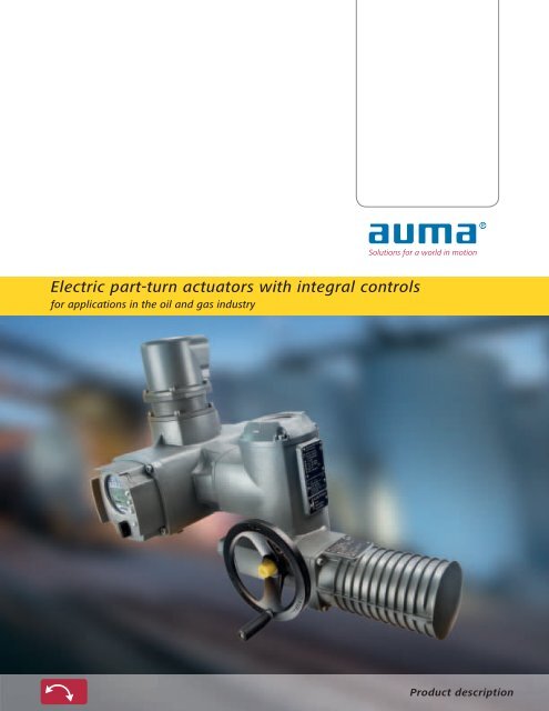
Electric part-turn actuators with integral controls<br />
for applications in the oil and gas industry<br />
Product description
The actuator specialist<br />
AUMA are one of the leading manufacturers of electric<br />
actuators, actuator controls and valve gearboxes for the<br />
automation of industrial valves in the oil and gas industry.<br />
AUMA have 50 years of experience in research & development<br />
and manufacture of electric multi-turn and part-turn<br />
actuators. AUMA manufacture their products not only in<br />
Germany but also in the Unites States. Three service centers<br />
have been set up to offer service support. 2,300 employees<br />
belong to the AUMA group worldwide.<br />
AUMA automate valves<br />
AUMA actuators have to stand up to a multitude of <strong>com</strong>plex<br />
requirements and operate in the most different applications<br />
– this is our daily business. The modular AUMA design<br />
principle forms the basis of the long-term product policy and<br />
offers the required flexibility to adapt our range of actuators<br />
to suit customer requirements.<br />
Global presence<br />
For this purpose, you have to know your markets well.<br />
Thinking globally means acting locally. A <strong>com</strong>prehensive<br />
worldwide sales and service network ensures that there is a<br />
<strong>com</strong>petent local contact for every customer.<br />
Single source supply<br />
From product development to device testing, to final<br />
inspection, AUMA offer continuous manufacturing and quality<br />
assurance processes which are subject to constant review.<br />
Since 1964, AUMA have established an excellent brand<br />
name in the world of actuators. Reliability and innovation<br />
are concepts which are closely linked with AUMA. This is<br />
above all to be credited to AUMA’s dedicated employees<br />
who work devotedly on the future of electric actuators.<br />
2 |
Contents<br />
The actuator specialist 2<br />
Applications 4<br />
AUMA actuators for the oil and gas industry 5<br />
Service conditions 7<br />
Basics - Main functions of actuators 8<br />
Basics - Controls concepts 10<br />
Integration within the DCS -<br />
AMExC and ACExC actuator controls 12<br />
Operation and clarity - ACExC local controls 14<br />
Communication - Tailor-made interfaces 18<br />
Electrical and valve connection 31<br />
Particular conditions - Local adaptations possible! 32<br />
Safe and reliable – in any circumstance 33<br />
Prevention, service life, maintenance -<br />
ACExC as test engineer 34<br />
Technical data 36<br />
Certificates and approvals 44<br />
Quality is not just a matter of trust 48<br />
AUMA worldwide 49<br />
Index 51<br />
Communication - Fieldbus 20<br />
Communication and device integration -<br />
SIMA Master Station 22<br />
Design principle 24<br />
Design principle 27<br />
Solutions for a world in motion<br />
This brochure will provide both the beginner and the<br />
expert with an overview of the functions and applications<br />
of AUMA SGExC .1 series actuators as well as the AMExC<br />
and ACExC actuator controls. It can be used as the basis to<br />
determine the suitability of a device for the chosen application.<br />
For detailed product selection, please refer to the separate<br />
data sheets. On request, AUMA engineers within field<br />
service and within our subsidiaries can assist you in defining<br />
the correct device for the application.<br />
2013.06.07<br />
The latest information on the AUMA products can be<br />
found on the Internet at www.auma.<strong>com</strong>. All documents,<br />
including dimensional drawings, wiring diagrams, technical<br />
and electrical data sheets as well as final inspection records<br />
are available on the Internet in digital form.<br />
| 3
Applications<br />
Tank farms<br />
: Loading jetty<br />
: Storage<br />
: Distribution<br />
: Manifold<br />
: Metering<br />
Platforms<br />
: Wellhead control<br />
: Drilling & exploitation<br />
: Transmission<br />
: Separators<br />
: Gas lift<br />
: Manifold<br />
Refineries<br />
: Separators<br />
: Cracker & coker<br />
: Refining & treatment<br />
: Fire fighting<br />
: Isolation<br />
: ESD applications<br />
Transport<br />
: Terminals<br />
: Pipelines<br />
: Pumping stations<br />
: Booster<br />
: Pressure reduction<br />
: Fuelling<br />
4 |
SGExC part-turn<br />
actuator with<br />
ACExC controls<br />
GS part-turn gearbox<br />
with SAEx .2 multi-turn actuator<br />
AUMA actuators for the oil and gas industry<br />
AUMA part-turn actuators are used wherever the automation<br />
of a valve requires a part-turn movement, e.g. when<br />
using butterfly valves or ball valves. For a part-turn movement,<br />
less than one rotation at valve input is required for a<br />
<strong>com</strong>plete travel. A typical requirement is a swing angle of<br />
90°.<br />
AUMA SGExC part-turn actuators<br />
AUMA SGExC part-turn actuators are designed to meet<br />
the special requirements in the oil and gas sector. They are<br />
approved worldwide for installation in potentially explosive<br />
atmospheres.<br />
The key figures<br />
SGExC part-turn actuators are available in different sizes<br />
and versions. The following demands can be implemented:<br />
■ Torques between 100 Nm and 1,200 Nm<br />
■ Swing angles are adjustable between 80° – 110°. As an<br />
option, ranges between 30° and 320° are possible.<br />
■ Speeds between 4 s and 63 s<br />
For detailed information, refer to the separate technical<br />
data section from page 36.<br />
For applications requiring higher torques, <strong>com</strong>binations of<br />
AUMA SAEx part-turn actuators and GS part-turn gearboxes<br />
are particularly suitable. Torques up to 675,000 Nm can be<br />
achieved.<br />
Modular product concept<br />
As from the very beginning, AUMA have pursued and<br />
implemented their modular product portfolio. Consequently,<br />
SGExC part-turn actuators perfectly <strong>com</strong>bine with AUMA<br />
AMExC and ACExC integral actuator controls.<br />
| 5
The environmental conditions in the oil and gas industry<br />
are mostly extreme. Salt-laden air in offshore applications,<br />
aggressive atmospheres in refineries or rough operation -<br />
AUMA devices must operate reliably over many years without<br />
major maintenance requirements under all conditions.<br />
For this reason, AUMA have focussed on making their<br />
devices resistant to the most unfavourable conditions and<br />
have adapted protective measures to the state-of-the-art<br />
technology.<br />
Ambient temperatures<br />
AUMA actuators are used in both hot and cold environments.<br />
Adapted versions with large temperature ranges are<br />
available to suit various ambient temperatures.<br />
Approved temperature ranges are determined within the<br />
framework of explosion protection qualification. They differ<br />
depending on the region and certificate. Refer to page 44<br />
for a detailed list.<br />
Enclosure protection IP 67<br />
As standard, AUMA SGExC part-turn actuators meet the<br />
requirements of enclosure protection IP 67 according to EN<br />
60529.<br />
IP 67 means protection against immersion up to 1 m head<br />
of water for max. 30 minutes.<br />
Enclosure protection IP 68<br />
Upon special request, part-turn actuators are available<br />
with improved enclosure protection IP 68 according to EN<br />
60529. IP 68 means protection against continuous immersion<br />
up to 6 m head of water for minimum 72 hours. During<br />
continuous immersion, up to 10 operations are permissible.<br />
In order to guarantee enclosure protection IP 68, suitable<br />
cable glands must be used. They are not part of the standard<br />
supply, but can be provided by AUMA on request.<br />
Service conditions<br />
6 |
Corrosion protection<br />
AUMA corrosion protection is one of a kind in the world<br />
of actuators. Based on chemical preliminary wet treatment<br />
with subsequent double powder coating of individual parts,<br />
the standard corrosion protection already efficiently protects<br />
against corrosion even under the most unfavourable<br />
conditions while providing high mechanical resistance. In<br />
<strong>com</strong>pliance with the corrosivity categories according to EN<br />
ISO 12944-2, various AUMA corrosion protection levels are<br />
provided to suit the different applications.<br />
Colour<br />
The standard colour is silver-grey (similar to RAL 7037).<br />
Other colours are possible on request.<br />
AUMA<br />
Classification of environments according to EN ISO 12944-2<br />
Atmospheric corrosivity categories<br />
Corrosion<br />
protection<br />
class<br />
Total film<br />
thickness<br />
Location<br />
C1 (very low): Heated buildings with clean atmospheres<br />
C2 (low): Unheated rooms and rural areas with low level of pollution<br />
Outdoor use of devices and for low atmosphere<br />
pollution<br />
C3 (medium): Production rooms with humidity and moderate pollution.<br />
Urban and industrial areas with moderate sulphur dioxide pollution<br />
C4 (high): Chemical plants and areas with moderate salinity<br />
KS<br />
140 μm<br />
Use of devices in occasionally or permanently<br />
aggressive atmospheres with a moderate pollutant<br />
concentration<br />
C5-I (very high, industrial): Permanently high condensation with high<br />
pollution<br />
C5-M (very high, marine): Permanently high condensation with high<br />
salinity and high pollution<br />
KX<br />
KX-G<br />
(aluminiumfree)<br />
200 μm<br />
Use of devices in extremely aggressive atmospheres<br />
with high humidity and high pollutant<br />
concentration<br />
Use of devices in extremely aggressive atmospheres<br />
with high humidity, high salinity and<br />
high pollutant concentration (e.g. cooling<br />
tower, offshore)<br />
Fireproof actuators (option)<br />
In case of fire, AUMA fireproof actuators can contribute a<br />
great deal to limiting the risks. The functionality, application<br />
possibilities, operation and user friendliness are <strong>com</strong>parable<br />
to non-fireproof actuators.<br />
The special coating applied to these actuators renders the<br />
devices <strong>com</strong>pletely operational during minimum 30 minutes<br />
at a temperature up to 1,100 °C. Within this period of time<br />
the corresponding valve can be operated.<br />
As an alternative, the actuators can be installed in fireproof<br />
boxes.<br />
SGExC in fireproof version<br />
| 7
OPEN-CLOSE duty and positioning duty<br />
AUMA SGExC actuators are suitable for open-close duty<br />
and positioning mode.<br />
OPEN - CLOSE duty<br />
Actuators for open - close duty are appropriate for<br />
automating shut-off valves. They are rarely operated; when<br />
operated, they cover the <strong>com</strong>plete swing angle. The time<br />
difference between two travels can amount to minutes or<br />
even to months.<br />
Due to the fact that during normal operation only the<br />
states OPEN and CLOSED are relevant, the discrete <strong>com</strong>mands<br />
run OPEN and run CLOSE are usually sufficient.<br />
Once the <strong>com</strong>mand is executed and the end position is<br />
reached, controls issue the feedback signals End position<br />
OPEN or End position CLOSED.<br />
Positioning duty<br />
One or several predefined intermediate positions are<br />
used to set the required flow rate through a pipeline for<br />
example. For this type of application, the intervals between<br />
two operations are generally considerably shorter than in<br />
open - close duty. Intermediate positions are subsequently<br />
approached via operation <strong>com</strong>mands OPEN or CLOSE<br />
or own intermediate position <strong>com</strong>mands are issued to<br />
approach the intermediate positions.<br />
Once the issued <strong>com</strong>mand is executed and the intermediate<br />
position is reached, controls send respective feedback<br />
signals to the DCS.<br />
Basics - Main functions of actuators<br />
OPEN - CLOSE duty<br />
[1] Command Run CLOSE [2] Feedback signal End position CLOSED<br />
8 |
Switching off in the end positions<br />
One of the key actuator functions is the automatic cut-off<br />
once an end position is reached. Two different mechanisms<br />
are available for SGExC part-turn actuators and are applied<br />
depending on the type of valve.<br />
Limit seating<br />
Switching points for end positions are set in the actuator.<br />
As soon as the set switching point is reached, controls<br />
automatically switch off the actuator.<br />
Torque seating<br />
This type of seating is used if the valve has to be moved<br />
to end position CLOSED at a defined torque to ensure correct<br />
seating. As soon as the preset torque is applied at the<br />
valve end position, controls automatically switch off the<br />
actuator.<br />
Protective functions<br />
Overload protection for the valve<br />
If an excessive torque is applied during travel, e.g. due to<br />
a trapped object or deposits within the valve, the controls<br />
switch off the actuator to protect the valve.<br />
Thermal motor protection<br />
PTC thermistors or thermoswitches (as an option) in<br />
the motor winding trip as soon as the motor temperature<br />
exceeds 140 °C. Embedded within the controls, they optimally<br />
protect the motor winding against overheating.<br />
PTC thermistors or thermoswitches offer better protection<br />
than thermal overload relays, since the temperature rise is<br />
measured within the motor winding.<br />
The type of seating must be programmed within controls,<br />
either at external controls or at AUMA integral actuator<br />
controls. For actuators with AMExC or ACExC integral controls,<br />
the type of seating is selected in the integral actuator<br />
controls and may even differ for the two end positions.<br />
| 9
AUMA NORM<br />
Power supply, e.g. 400 V 3-ph AC current<br />
With AMExC integral controls<br />
L2<br />
L1 PE<br />
L3<br />
With ACExC integral controls<br />
TSC RO<br />
LSC<br />
TSO<br />
RC<br />
LSO M<br />
Basics - Controls concepts<br />
External controls<br />
In principle, AUMA actuators may be integrated within any<br />
automation system. The state-of-the-art solution is to equip For this controls concept, actuators contain no or only<br />
the actuator with integral controls to eliminate the time-consuming<br />
and costly engineering, installation and documentation<br />
few electronic <strong>com</strong>ponents.<br />
All actuator signals, limit switch signals, torque switch<br />
for external controls. A further benefit in favour of integral<br />
signals, motor protection or valve position are centrally processed<br />
in an external PLC. During programming, care<br />
controls is the easy <strong>com</strong>missioning.<br />
must<br />
been taken to consider the required protective mechanisms<br />
and to minimise delay time.<br />
The switchgear for motor control is installed within a<br />
control cabinet and wired accordingly to the actuator.<br />
If local controls are required, they have to be installed<br />
and programmed accordingly within the PLC.<br />
In this configuration, AUMA actuators are designated as<br />
AUMA NORM.<br />
10 |
Integral controls<br />
Actuators with integral controls are immediately ready<br />
for use. The controls are perfectly adapted to the actuator.<br />
As soon as the power supply has been established, the<br />
actuator can be operated via the operation elements on<br />
the local controls.<br />
The actuator can be <strong>com</strong>pletely set on site, without<br />
requiring direct connection to the DCS. Only operation<br />
<strong>com</strong>mands and feedback signals are still exchanged<br />
between the control system and the actuator. Motor<br />
switching is performed within the device and without<br />
delay.<br />
The actuators can be equipped with AMExC or ACExC<br />
integral controls. Distinction between both is made in their<br />
functional features.<br />
Fieldbus<br />
By using a single data transmission medium for all signals<br />
from many devices, the structure of fieldbus systems can be<br />
kept very clear and simple.<br />
While the control cabinet of <strong>com</strong>monly used systems is<br />
filled with input and output sub-assemblies, fieldbus only<br />
requires one single interface.<br />
Digitization of all data made it possible to extend functionality.<br />
This includes the field device setting via the DCS or<br />
request for all device data from the control room.<br />
AUMA actuators with integral actuator controls are available<br />
with interfaces to all <strong>com</strong>mon fieldbus systems within<br />
process automation.<br />
| 11
Integration within the DCS - AMExC and ACExC actuator controls<br />
The integral controls evaluate the actuator signals and<br />
operation <strong>com</strong>mands and automatically perform the required<br />
switching procedures without delay, using the installed<br />
switchgear, reversing contactors or thyristors.<br />
After analysis, the controls supply the actuator signals as<br />
feedback signals to the host level.<br />
The integral controls allow for local actuator operation.<br />
AMExC and ACExC controls are <strong>com</strong>patible with other<br />
AUMA actuator series. From the DCS point of view, a homogeneous<br />
appearance is created even for different valve and<br />
actuator types.<br />
Please refer to page 43 for a detailed overview of the<br />
controls’ functions.<br />
AMExC 01.1<br />
Due to their simple logic, AMExC controls are the ideal<br />
solution wherever the requirement is limited to opening or<br />
closing valves, wherever conventional parallel <strong>com</strong>munication<br />
is used and data exchange is reduced to the absolute<br />
minimum.<br />
At the time of <strong>com</strong>missioning, only a small number of<br />
parameters are defined via DIP switches, e.g. the type of<br />
seating.<br />
Actuator control is made via operation <strong>com</strong>mands OPEN,<br />
STOP, CLOSE. Reaching an end position and a collective fault<br />
signal are reported back to the DCS as feedback signals.<br />
These signals are visually displayed at the local controls via<br />
the indication lights. As an option, the valve position can be<br />
transmitted as 0/4 – 20 mA signal to the DCS.<br />
Further options include a 3-point positioner allowing<br />
actuator control via the 0/4 – 20 mA signal and simple<br />
Profibus DP and Modbus RTU interfaces.<br />
12 |
ACExC 01.2<br />
ACExC controls are your perfect solution if the application<br />
requires data logging, configurable user interface or if valve<br />
and actuator are to be implemented into a Plant Asset Management<br />
System by advanced diagnostic functions.<br />
AC controls are equipped with a large and freely programmable<br />
parallel interface and/or interfaces to established fieldbus<br />
systems within process automation, including Profibus<br />
DP-V2.<br />
With the development of the ACExC 01.2, particular<br />
emphasis was laid on user-friendliness and the ease of integration<br />
of actuators into the DCS. The large graphic display<br />
is used to perform menu-controlled programming of the<br />
controls, optionally using AUMA ToolSuite via wireless Bluetooth<br />
connection. For fieldbus connections, AC programming<br />
can be performed from the control room.<br />
The diagnostic functions <strong>com</strong>prise a time-stamped event<br />
report, torque characteristics logging, or counting the number<br />
of starts and motor running times.<br />
Further to the basic functions, they offer a number of<br />
options to meet special demands. These include torque<br />
by-pass to unseat valves if tightly seated or functions for<br />
modifying operating times to avoid water hammer within<br />
pipelines.<br />
| 13
[2]<br />
[4]<br />
[1]<br />
[3]<br />
Operation and clarity - ACExC local controls<br />
Modern actuators can be adapted to special application<br />
requirements by a multitude of parameters. Monitoring and<br />
diagnostic functions generate signals and collect operating<br />
parameters.<br />
For actuators with AMExC integral controls, the programming<br />
possibilities and the number of signals are limited.<br />
Accessing the considerably more detailed ACExC data is facilitated<br />
by the clearly structured and intuitive user interface.<br />
The display structure is user-friendly, in plain text and<br />
available in a large number of languages.<br />
Signals classified in <strong>com</strong>pliance with NAMUR<br />
During operation, the plant operators may be confused to<br />
receive device-specific signals. For this purpose, ACExC status<br />
signals are classified in <strong>com</strong>pliance with NAMUR re<strong>com</strong>mendation<br />
NE 107. Refer also to page 35.<br />
Password protection<br />
The ACExC password protection is an important safety<br />
feature. Especially if devices are freely accessible, nonauthorised<br />
persons are not able to perform any modification.<br />
[1] Backlit display<br />
The graphic display shows texts and graphic elements as<br />
well as characteristics. The display is permanently lit; during<br />
use the backlight shines brighter.<br />
[2] Indication lights<br />
Visual actuator signals via indication lights can be<br />
programmed. Signals, which are required to be recognisable<br />
from a long distance, can be assigned accordingly. The<br />
default factory signal setting is: End position CLOSED (yellow),<br />
end position OPEN (green), torque fault OPEN, torque<br />
fault CLOSE and motor protection tripped (all red).<br />
14 |
[5]<br />
[8]<br />
[6]<br />
[9]<br />
[7]<br />
[10]<br />
[3] Selecting the control mode<br />
The selector switch LOCAL - OFF - REMOTE is used to<br />
define whether the actuator is operated from remote or via<br />
the local controls. In OFF position, hold down the RESET button<br />
for a few seconds to enter the programming menu.<br />
[4] Operation and programming<br />
Depending on the selector switch position, the push<br />
buttons enable either electric actuator operation, status<br />
signals requests or menu navigation.<br />
[5] Displaying the valve position<br />
The large display allows the operator to read the valve<br />
position even from a long distance.<br />
[6] Displaying operation <strong>com</strong>mands/setpoints<br />
Operation <strong>com</strong>mands and setpoints emitted from the<br />
DCS can be displayed.<br />
[7] Diagnostic/monitoring displays<br />
Actuator operation is subjected to special basic conditions.<br />
They are permanently monitored. When exceeding<br />
permissible limits e.g. temperature, the ACExC generates a<br />
warning signal. Exact values can be requested via the display.<br />
[8] Main menu<br />
The main menu allows actuator data requests and<br />
operation parameter modifications.<br />
[9] Non-intrusive setting<br />
If the actuator is equipped with an electronic control<br />
unit, the end positions and tripping torques can be set using<br />
the display without opening the device housing or using setting<br />
tools.<br />
[10] Failure<br />
In case of failure, the colour of the display colour<br />
changes to red. The cause for failure can be requested via<br />
the display.<br />
| 15
For actuators with AMExC or ACExC integral controls,<br />
all settings can be directly performed at the actuator. If the<br />
actuator is equipped with an electronic control unit and<br />
ACExC, settings are made via the display, without opening<br />
the housing.<br />
The actuators with ACExC can be <strong>com</strong>missioned via<br />
AUMA ToolSuite Commissioning and Diagnostic Tool (CDT).<br />
This tool allows clearer presentation of parameters and<br />
actuator data. Furthermore, it converts a PDA or a laptop to<br />
a remote control for the actuator.<br />
AUMA ToolSuite database<br />
Actuator data can be archived in the AUMA ToolSuite<br />
database. This supports, for example, an available Plant<br />
Asset Management system. If an ACExC has to be replaced,<br />
all database parameters can be uploaded to the replacement<br />
device, thus quickly restoring the previous functionality.<br />
Wireless connection<br />
Connection between actuator and programming device is<br />
based on Bluetooth standard, supported by most laptops or<br />
PDAs. The connection is password-protected to exclude any<br />
unauthorised access.<br />
The addressed actuator indicates the access via a blue<br />
indication light. The device can be clearly identified due to<br />
the works number or a customer-specific name assignment.<br />
AUMA ToolSuite for testing the fieldbus interface<br />
The correct functioning of AUMA ToolSuite can be tested<br />
via the actuator fieldbus interface. From the actuator point<br />
of view and for the duration of the test phase, the laptop<br />
equipped with AUMA ToolSuite will take over the master<br />
function.<br />
AUMA ToolSuite diagnostic tool<br />
AUMA ToolSuite is the ideal tool to analyse the timestamped<br />
ACExC event report or to <strong>com</strong>pare torque characteristics<br />
taken at different points in time. This allows reliable<br />
<strong>com</strong>parisons of previous operations of actuator and valve.<br />
Operation and clarity - AUMA ToolSuite for ACExC<br />
■<br />
■<br />
■<br />
■<br />
■<br />
■<br />
■<br />
AUMA ToolSuite functions<br />
Programming the operation parameters<br />
Reading all operational data<br />
Reading the event report<br />
Actuator operation<br />
Archiving the ACExC data in a database<br />
Transferring parameter data from the database to the<br />
ACExC<br />
Testing the fieldbus interface<br />
AUMA ToolSuite and display texts of the ACExC are currently<br />
available in 33 languages, including Chinese and Arabic.<br />
[1]<br />
[2]<br />
16 |
[3]<br />
[4]<br />
[5]<br />
[1] AUMA ToolSuite for laptop<br />
System requirements<br />
■ Bluetooth interface<br />
■ Windows XP, Windows Vista, Windows 7<br />
[2] AUMA ToolSuite for PDA<br />
System requirements<br />
■ Bluetooth interface<br />
■ Windows Mobile<br />
[3] Programming via AUMA ToolSuite<br />
The parameter display is more <strong>com</strong>fortable in the AUMA<br />
ToolSuite than on the ACExC display. The parameters may<br />
only be changed when entering a password.<br />
[5] ToolTips<br />
AUMA ToolSuite supplies an explanation for each<br />
selected parameter.<br />
Database<br />
All parameters, operating data, events, product data can<br />
be archived in a database.<br />
Event report<br />
AUMA ToolSuite allows clear presentation of the event<br />
report. It is possible to select events according to definable<br />
criteria using a search function.<br />
[4] Remote control<br />
Remote control allows actuator operation via AUMA<br />
ToolSuite. At the same time, all indication light signals and all<br />
status signals which can be indicated on the ACExC display<br />
can also be clearly shown.<br />
| 17
Although the mechanical interfaces between actuators<br />
and valves have been standardised for many decades and<br />
are stable, there are a multitude of different interfaces to<br />
the DCS. In spite of efforts for standardisation, <strong>com</strong>munication<br />
technology is subject to constant improvement due to<br />
continuous developments within the electronics sector.<br />
Due to the modular product range, AUMA are in a position<br />
to offer an interface for any system, from the AUMA<br />
NORM actuator without integral controls to the actuator<br />
with ACExC controls, programmable from the control room<br />
via fieldbus.<br />
Furthermore, the AUMA modularity makes it possible to<br />
upgrade AUMA actuators to a new DCS.<br />
Parallel signal transmission to<br />
DCS - AMExC<br />
For the AMExC, all input and outputs are hard wired.<br />
Please refer to the terminal plan for respective assignment.<br />
■<br />
■<br />
Three binary inputs for the control <strong>com</strong>mands OPEN,<br />
STOP, CLOSE<br />
Five binary outputs with the following assignments: End<br />
position CLOSED, end position OPEN, selector switch in<br />
REMOTE, selector switch in LOCAL, collective fault signal<br />
■ Alternatively to the control inputs, an analogue 0/4 – 20<br />
mA input for positioner control<br />
■<br />
As an option, an analogue 0/4 – 20 mA output for<br />
remote position indication.<br />
The binary inputs and outputs are potential-free, the analogue<br />
output is galvanically isolated.<br />
Communication - Tailor-made interfaces<br />
18 |
Parallel signal transmission to<br />
DCS - ACExC<br />
ACExC supplies a large number of feedback signals. The<br />
plant operator decides which signals are to be transmitted.<br />
Assignment of outputs and inputs, if available, can be modified<br />
at a later date with the ACExC device setting.<br />
■<br />
■<br />
■<br />
■<br />
Depending on the version, the ACExC provides:<br />
Up to ten binary inputs<br />
e.g. operation <strong>com</strong>mands OPEN, STOP, CLOSE; intermediate<br />
position control; release signals for local controls,<br />
emergency <strong>com</strong>mands, etc.<br />
Up to twelve binary outputs<br />
e.g. for feedback of end position, intermediate positions,<br />
selector switch position, failures, etc.<br />
Up to two analogue inputs (0/4 – 20 mA)<br />
e.g. setpoint for controlling the positioner<br />
Up to two analogue outputs (0/4 – 20 mA)<br />
e.g. for feedback of valve position or torque<br />
The binary inputs and outputs are potential-free, analogue<br />
outputs are galvanically isolated.<br />
Serial <strong>com</strong>munication via fieldbus - AMExC<br />
and ACExC<br />
From the fieldbus point of view, the ACExC is state-of-theart.<br />
AUMA permanently keep track on further developments<br />
of fieldbus protocols and consequently implement all elements<br />
of vital importance for valve automation applications.<br />
One key advantage is that the ACExC is fully upgradable<br />
and can thus be adapted to new developments.<br />
Controls are available with the following fieldbus interfaces:<br />
AMExC<br />
ACExC<br />
Profi bus DP ■ ■<br />
Profi bus<br />
DP-V1 and DP-V2<br />
– ■<br />
Modbus RTU ■ ■<br />
Foundation Fieldbus – ■<br />
Fieldbus interfaces can be <strong>com</strong>bined within a device<br />
equipped with parallel interfaces.<br />
For further information on fieldbus systems, please refer<br />
to the following pages.<br />
[3]<br />
ACExC as fieldbus data transmitter<br />
[1]<br />
As an option, an ACExC with fieldbus interface can be<br />
supplied with four binary and/or two analogue inputs [1].<br />
They are used to connect conventional sensors [2] to the<br />
ACExC. The ACExC processes the sensor data for transmission<br />
via the fieldbus [3].<br />
[2]<br />
| 19
Profibus<br />
Profibus offers a <strong>com</strong>plete family of fieldbus versions;<br />
Profibus PA for process automation, Profinet for data transmission<br />
on Ethernet and Profibus DP for automating plants<br />
and machines. Due to its simple and robust physical layer<br />
(RS-485) and the different service levels DP-V0 (fast cyclic<br />
and deterministic data exchange), DP-V1 (acyclic access to<br />
device parameters and diagnostic data) as well as DP-V2 (further<br />
functions such as time stamp or redundancy), Profibus<br />
DP is the ideal solution for plant automation.<br />
■ International standard (www.profibus.<strong>com</strong>)<br />
■ Worldwide availability<br />
■ Large number of units installed<br />
■ Standardised integration within the DCS (FDT, EDD)<br />
■ Large selection of devices<br />
Modbus<br />
Modbus is a <strong>com</strong>paratively simple but multi-functional<br />
fieldbus protocol. It offers all services required for plant<br />
automation (e.g. exchange of simple, binary information,<br />
analogue values, device parameters or diagnostic data).<br />
For plant automation, the simple and robust physical layer<br />
RS-485 is often used.<br />
On the basis of this physical layer, Modbus supports various<br />
telegram formats (e.g. Modbus RTU or Modbus ASCII).<br />
Using the Modbus TCP/IP version based on Ethernet, vertical<br />
integration into a host automation system is simplified.<br />
■<br />
■<br />
■<br />
■<br />
International standard (www.modbus.org)<br />
Simple protocol<br />
Widely implemented<br />
Largely sufficient for many simple automation tasks<br />
Communication - Fieldbus<br />
For Profibus DP and Modbus RTU, the basic topology is the line/tree structure via RS-485.<br />
AUMA actuators and Profibus DP<br />
AUMA actuators and Modbus RTU<br />
■<br />
Supports Profibus DP-V0, DP-V1 and DP-V2<br />
■<br />
Fast data exchange (up to 115.2 kbit/s - corresponds<br />
■<br />
High speed data exchange (up to 1.5 Mbit/s - corre-<br />
to approx. 30 ms/actuator)<br />
sponds to approx. 0.3 ms/actuator)<br />
■<br />
Cable length up to approx. 10 km (without repeater<br />
■<br />
Integration within the DCS via FDT or EDD<br />
up to 1,200 m)<br />
■<br />
Cable length up to approx. 10 km (without repeater<br />
■<br />
Up to 247 devices can be connected<br />
up to 1,200 m)<br />
■<br />
Redundant line topology as an option<br />
■<br />
Up to 126 devices can be connected<br />
■<br />
Additional parallel <strong>com</strong>munication to safety PLC as an<br />
■<br />
Redundant line topology as an option<br />
option<br />
■<br />
Additional parallel <strong>com</strong>munication to safety PLC as an<br />
option<br />
20 |
Foundation Fieldbus<br />
The basic idea behind Foundation Fieldbus (FF) is to quit<br />
the classic master - slave concept and to distribute the tasks<br />
within the automation system to the <strong>com</strong>ponents involved.<br />
For this reason, Foundation Fieldbus is more than a conventional<br />
fieldbus system.<br />
This leads to the following consequences:<br />
■ Information is no longer bidirectionally exchanged<br />
between field device and master: all information is generally<br />
available to all participants.<br />
■ A central master processing field device data is no longer<br />
required.<br />
■ The schedule of the bus <strong>com</strong>munication is controlled<br />
by the "Link Active Scheduler" (LAS). It ensures that the<br />
field devices <strong>com</strong>municate one after the other.<br />
■ Integration within the DCS via standardised function<br />
blocks<br />
Wireless<br />
Radio transmission is based on wireless <strong>com</strong>munication<br />
standard IEEE 802.15.4 (ISM band). Communication provides<br />
a coding to protect the data transmission and parameterization<br />
of field devices against unauthorised modification.<br />
The network organises itself (mesh network). Simply enter<br />
a network ID to add a field device to an existing network;<br />
the topology will organise itself automatically. If participants<br />
are separated in space, even larger distances can be covered<br />
as the intermediate participants act as repeaters.<br />
If one participant fails as transmission medium, transmission<br />
is automatically established via another participant.<br />
HSE bus<br />
Linking<br />
device<br />
H1 bus<br />
Junction<br />
box<br />
AUMA actuators and Foundation Fieldbus<br />
■<br />
■<br />
■<br />
■<br />
■<br />
■<br />
■<br />
AUMA actuators support the FF-H1 version<br />
Data exchange at 31.25 kbit/s, typical cycle times<br />
500 ms – 2 s, depending on the number of devices<br />
Cable length up to approx. 9.5 km (without repeater up<br />
to 1,900 m)<br />
Up to 240 devices can be connected<br />
HSE bus: Connection to DCS<br />
Linking device: Connection HSE - H1 bus<br />
Junction box: Signal amplification, allows branching<br />
| 21
AUMA as system integrator<br />
AUMA not only possess the expertise to manufacture<br />
electric actuators but also have the ability to perfectly integrate<br />
actuators into any automation environment.<br />
For this, the SIMA Master Station is a key element. The<br />
SIMA Master Station works with open fieldbus protocols<br />
such as Profibus DP or Modbus RTU.<br />
The SIMA is based on standardised industrial <strong>com</strong>puter<br />
<strong>com</strong>ponents and has been expanded by the required fieldbus<br />
interfaces. The entire hardware is integrated in a solid 19"<br />
industrial housing with EMC protection. The SIMA is available<br />
both with or without touchscreen.<br />
Tasks for SIMA Master Station<br />
■ SIMA as <strong>com</strong>missioning system allows for independent<br />
<strong>com</strong>missioning of the connected actuator network.<br />
■ SIMA as network manager controls the <strong>com</strong>munication<br />
to the field devices, including redundant data channels.<br />
■ SIMA as data concentrator facilitates data access of the<br />
connected actuators. Data transmission to the control<br />
room only <strong>com</strong>prises information required for regular<br />
operation.<br />
■ In the event of failures, the SIMA as diagnostic tool supports<br />
fast fault identification and remedy.<br />
■ SIMA as a protocol converter is used to adapt the actuator<br />
network to the available interfaces of the DCS.<br />
Communication<br />
For the <strong>com</strong>munication with field devices, SIMA supports<br />
standardised fieldbus protocols such as Profibus DP or Modbus<br />
RTU. The cable types specified in the fieldbus standards<br />
are used as transmission medium.<br />
Up to 32 stations can be connected to one bus segment.<br />
When using repeaters, up to 247 participants can be connected.<br />
Communication with the DCS can be performed via Modbus<br />
RTU or Modbus TCP/IP. Moreover, customised RS-232<br />
solutions can be implemented.<br />
Safe redundancy<br />
SIMA supports various redundancy concepts. Both redundancy<br />
to the AUMA field devices and/or to the DCS as well<br />
as SIMA master redundancy are possible. In case of loss of<br />
<strong>com</strong>munication or master failure, automatic change-over to<br />
the redundant <strong>com</strong>ponent will be performed.<br />
Communication and device integration - SIMA Master Station<br />
Control system<br />
[2]<br />
[1] SIMA Master Station<br />
[2] Redundant data <strong>com</strong>munication<br />
[3] Redundancy using two SIMA Master Stations<br />
[4] AUMA actuators<br />
[1]<br />
[3]<br />
[4]<br />
[4] [4]<br />
22 |
Covering large distances<br />
Redundant Modbus RTU loop<br />
With the SIMA Master Station, AUMA offer the ideal<br />
solution to cover large distances - this might occur for<br />
tank farms - with simultaneous data channel redundancy.<br />
Costly glass fibre technology is not required; in spite of the<br />
long network cable length of up to 296 km (refer to graph<br />
below), standard RS-485 fieldbus cables can be used for data<br />
transmission.<br />
Wireless<br />
A further option for data exchange via large distances is<br />
offered by the wireless technology. AUMA actuators with<br />
ACExC integral controls and SIMA are available with wireless<br />
interfaces.<br />
Modbus RTU in redundant loop topology with SIMA Master Station<br />
■ Redundant loop topology via RS-485<br />
■ Automatic setting of desired data transmission rate at all<br />
■ Fast data exchange<br />
actuators<br />
(up to 115.2 kbit/s - corresponds to approx. 30 ms/ ■ Redundant <strong>com</strong>munication to the DCS as an option<br />
actuator)<br />
■ Redundant SIMA Master Station as an option<br />
■ Length of cable up to 296 km<br />
■ Additional parallel <strong>com</strong>munication to safety PLC as an<br />
■ Up to 247 devices can be connected<br />
option<br />
■ Automatic slave address assignment to all actuators<br />
| 23
Design principle<br />
AMExC integrl controls<br />
Controls <strong>com</strong>prising easy logic to process limit and<br />
torque signals as well as the control <strong>com</strong>mands OPEN,<br />
STOP, CLOSE.<br />
For further information, please refer to pages 12 and<br />
41 et seqq.<br />
[3a]<br />
[4]<br />
[5]<br />
[3]<br />
[2]<br />
[1]<br />
[1] AMExC local controls<br />
The actuator can be operated on site via local<br />
controls.<br />
Three push buttons on local controls can locally<br />
issue the <strong>com</strong>mands OPEN, STOP and CLOSE<br />
Three indication lights signal the actuator<br />
status: end position CLOSED, collective fault signal<br />
and end position OPEN.<br />
The selector switch LOCAL - OFF - REMOTE<br />
allows to select between local control and remote<br />
DCS control.<br />
[2] Electronics<br />
Integral controls contain power supply unit,<br />
interfaces to the DCS as well as PCBs with electronics<br />
required to process operation <strong>com</strong>mands and<br />
feedback signals.<br />
[3] Electrical plug/socket connection<br />
Both actuator and controls use plug/socket<br />
electrical connection.<br />
During maintenance work, the wiring remains<br />
undisturbed; electrical connections can be quickly<br />
separated and reconnected. For further information,<br />
please refer to pages 30 and 40.<br />
All electrical connections are double-sealed,<br />
i.e. there is an additional sealing between terminal<br />
<strong>com</strong>partment and interior of controls (3a).<br />
24 |
ACExC integral controls<br />
Microprocessor based controls for functionally sophisticated<br />
applications and for integration of actuators into<br />
fieldbus systems<br />
When <strong>com</strong>bined with the electronic control unit, all<br />
settings can be performed without opening the housing.<br />
The programming via menu navigation is made directly<br />
at the device or wireless via Bluetooth using the AUMA<br />
ToolSuite.<br />
For further information, please refer to pages 13<br />
and 41 et seqq.<br />
[3]<br />
[6] ACExC local controls<br />
The actuator can be operated on site via local<br />
controls.<br />
A large graphic display indicates actuator status<br />
in more than 30 language options.<br />
Push buttons on local controls can locally issue<br />
the <strong>com</strong>mands OPEN, STOP, CLOSE and RESET.<br />
Five indication lights signal the actuator status:<br />
end position CLOSED, torque fault in direction<br />
CLOSE, motor protection tripped, torque fault in<br />
direction OPEN and end position OPEN<br />
The selector switch LOCAL - OFF - REMOTE<br />
allows to select between local control and remote<br />
DCS control.<br />
[5]<br />
[3a]<br />
[4]<br />
[2]<br />
[6]<br />
[4] Switchgears<br />
As standard, reversing contactors are used for<br />
power switching. For special requirements, we re<strong>com</strong>mend<br />
using thyristor units not subject to wear<br />
(also refer to page 42).<br />
[5] Electrical connection to the actuator<br />
The electrical connection between integral controls<br />
and actuator is made by using a quick release<br />
plug/socket connector.<br />
|25
Design principle<br />
SGExC part-turn actuator<br />
in AUMA NORM version<br />
The basic AUMA NORM actuator consists of the following<br />
<strong>com</strong>ponents: motor, planetary gear and worm gearing,<br />
control unit, handwheel for emergency operation, electrical<br />
connection and valve attachment.<br />
This version does not include integral controls. Consequently,<br />
external controls and switchgears with respective<br />
logic are required.<br />
Usually, the NORM actuator is supplied with AMExC<br />
or ACExC integral controls. Due to the modular design<br />
principle, controls are simply connected to the actuator via<br />
a plug/socket connection.<br />
[3]<br />
[7/8]<br />
[2]<br />
[1]<br />
[6]<br />
27 |
Control unit<br />
The actuator is equipped with the control<br />
unit accepting the following tasks:<br />
[7]<br />
[7a]<br />
■<br />
Determining the valve position and torque<br />
applied<br />
■<br />
Setting the valve end positions and the<br />
tripping torques to protect the valve<br />
■<br />
against excessive load.<br />
Depending on the requirement, a control<br />
[7f]<br />
[7b]<br />
unit is installed either as electromechnical<br />
or electronic version.<br />
[7e]<br />
[7c]<br />
[7d]<br />
[4]<br />
[8]<br />
[8a]<br />
[5]<br />
[8b]<br />
[8d]<br />
[8c]<br />
| 28
[1] Gearing<br />
Reduction of motor speed to the desired partturn<br />
movement is achieved by means of a worm<br />
gearing in <strong>com</strong>bination with a planetary gear.<br />
The worm gearing is self-locking. Due to the<br />
design, the gearing produces a counter torque to<br />
output drive torque preventing that valve position<br />
changes at standstill.<br />
[2] Mechanical end stops<br />
Limit swing angles to protect the valve during<br />
emergency and manual operation. They allow precise<br />
approaching of end positions in manual operation.<br />
For the AUMA design, the travelling nut [a]<br />
travels between both end stops [b] during operation.<br />
Advantages of this design:<br />
■<br />
The low input torques and not the high output<br />
torques have an impact on the end stops.<br />
■<br />
End stops are separate from actuator housing.<br />
Excessive input torques have no impact on the<br />
housing.<br />
[a]<br />
[4] Motor<br />
3-phase AC, 1-phase AC and DC motors with<br />
high starting torques, developed especially for valve<br />
automation. They are of <strong>com</strong>pact and sturdy design<br />
and are characterised by a high starting torque to<br />
unseat blocked valves from their end positions. Thermal<br />
protection is ensured by thermoswitches or PTC<br />
thermistors.<br />
The motor is connected via an internal plug/<br />
socket connector. This allows quick motor replacement<br />
, e.g. for changing the output speed.<br />
For further information, please refer to page 39.<br />
[5] Handwheel<br />
A handwheel is used for setting the end positions<br />
and switching points during <strong>com</strong>missioning<br />
as well as emergency operation in case of a power<br />
failure.<br />
Manual operation is engaged by pulling and<br />
turning the handwheel. No switching is required.<br />
It is possible to activate manual operation while<br />
the motor is running.<br />
As an option, a locking device is available to<br />
prevent unauthorised use.<br />
[b]<br />
[6] Valve attachment<br />
Valve attachment using a plug-in coupling and a<br />
standardised flange in <strong>com</strong>pliance with EN ISO 5211.<br />
Please refer to page 31 for further information on<br />
available variants.<br />
[3] Electrical plug/socket connection<br />
Both actuator and controls use plug/socket electrical<br />
connection.<br />
During maintenance work, the wiring remains<br />
undisturbed; electrical connections can be quickly<br />
separated and reconnected. For further information,<br />
please refer to pages 30 and 40.<br />
26 |
[7] Electromechanical control unit<br />
Used in actuators equipped with or without<br />
integral controls. Travel and torque are mechanically<br />
sensed. When reaching the tripping points, microswitches<br />
are operated<br />
For detailed information on electromechanical<br />
control unit, please refer to page 38.<br />
[7a] Limit and torque setting<br />
Switching points of end positions and tripping<br />
torques are mechanically set. After removal of housing<br />
cover and mechanical position indication, all<br />
setting elements are easily accessible.<br />
[7b]Torque sensing<br />
Torque is sensed via a lever system. When<br />
exceeding tripping torques in operation directions<br />
OPEN or CLOSE, respective microswitches are operated<br />
via cams.<br />
[7c] Limit sensing<br />
Valve position is mechanically sensed via a counter<br />
gear mechanism for directions OPEN and CLOSE.<br />
When reaching an end position, respective microswitches<br />
are operated via cams.<br />
[7d]Microswitches<br />
In the basic version, one limit switch each is<br />
available for the end positions OPEN and CLOSED<br />
and one torque switch for the directions OPEN and<br />
CLOSE.<br />
As an option, tandem switches are available to<br />
activate different potentials.<br />
[7f] Remote position transmitter (RWG)<br />
The optional RWG supports that the valve position<br />
is issued as continuous 0/4 – 20 mA signal to<br />
the DCS.<br />
Blinker transmitter for running indication<br />
(not shown)<br />
Throughout travel, the segment washer operates<br />
and releases the blinker switch.<br />
DUO limit switching (not shown)<br />
The optional DUO limit switching allows to set<br />
an additional switching point for each operation<br />
direction to signal an intermediate position.<br />
[8] Electronic control unit<br />
The electronic control unit can only be implemented<br />
in <strong>com</strong>bination with ACExC integral controls.<br />
Valve position and torque are mechanically<br />
transmitted and continuously recorded via the magnetic<br />
transmitter.<br />
ACExC controls internally process all signals and<br />
provides suitable feedback on the display and at the<br />
<strong>com</strong>munication interface.<br />
Valve position and tripping torques are set via<br />
ACExC local controls - without opening the housing.<br />
End position and torque settings are saved in the<br />
non-volatile memory of the control unit electronics.<br />
When replacing the ACExC controls, these settings<br />
still be retained.<br />
[8a] Limit sensing<br />
Current valve position is mechanically sensed via<br />
four gear stages.<br />
Consequently, the position is instantaneously<br />
and correctly detected even after power supply failure.<br />
Battery backup is not required.<br />
[8b] Torque sensing<br />
Like the valve position, applied torque is<br />
mechanically sensed. However, one gear stage suffices.<br />
[8c] Hall sensors<br />
High resolution Hall sensors continuously sense<br />
gear stage position of limit and torque. A continuous<br />
limit and torque signal is supplied by the device<br />
electronics.<br />
[7e/8d] Heater<br />
The heater minimises condensation within the<br />
switch <strong>com</strong>partment. Please refer to page 41 for<br />
detailed information.<br />
| 29
Electrical and valve connection<br />
[1] Electrical connection<br />
The electrical plug/socket connector is an<br />
essential <strong>com</strong>ponent of the modularity and forms<br />
a separate unit. The different connection types are<br />
<strong>com</strong>patible throughout all type ranges and can be<br />
used for actuators with or without integral controls.<br />
All electrical connections are double sealed.<br />
[1b]<br />
[1a] Plug/socket connector<br />
KP with screw-type terminals (standard)<br />
With optimised arrangement of the three cable<br />
entries and enlarged terminal <strong>com</strong>partment. Apart<br />
from connection terminals for power supply, the KP<br />
connector is equipped with 38 screw-type connectors<br />
for signal cable connection.<br />
[1a]<br />
[1b] Plug/socket connector<br />
KES with terminal blocks (option)<br />
Contains up to 48 terminal blocks to for signal<br />
cable connection. Use for voltage ranges<br />
exceeding 525 V and/or if many terminal connectors<br />
are required. The electrical connection has up to 6<br />
cable conduits.<br />
[1c] Plug/socket connector KES<br />
with FO cable coupler (option)<br />
Always in <strong>com</strong>bination with ACExC controls and<br />
signal transmision via FO cable. An FO cable coupler<br />
is installed instead of the terminals.<br />
[1d] Plug/socket connector KES<br />
with flameproof enclosure (option)<br />
In basic version, this connection corresponds to<br />
explosion protection 'increased safety'. As an option,<br />
all KES connections can be supplied enclosure protection<br />
‘flameproof enclosure’.<br />
[1a]<br />
30 |
[1c]<br />
[1d}<br />
[2] Valve attachment<br />
The part-turn actuator is connected to the valve<br />
using a mounting flange standardised according to<br />
EN ISO 5211.<br />
The torque is transmitted to the valve shaft via a<br />
separate plug-in coupling.<br />
In the basic version, the coupling is supplied<br />
unbored. However, upon request it can be provided<br />
with the bores as shown below.<br />
If the coupling is bored, it is supplied with a<br />
grub screw to fasten the coupling to the valve shaft.<br />
[2a] Unbored coupling<br />
Standard version. The finished machining is<br />
taken over by the customer.<br />
[2b] Bore with keyway<br />
The bore according to EN ISO 5211 can be<br />
supplied with one to four keyways. The keyways<br />
conform to DIN 6885 Part 1. For keyways with other<br />
dimensions please contact AUMA.<br />
[2c] Two-flat<br />
In <strong>com</strong>pliance with EN ISO 5211. For special<br />
dimensions please contact AUMA.<br />
[2d] Square bore<br />
In <strong>com</strong>pliance with EN ISO 5211. For special<br />
dimensions please contact AUMA.<br />
Extended coupling (not shown)<br />
For special valve designs, e.g. sunk stem or if an<br />
intermediate flange is required between gearbox and<br />
valve.<br />
Coupling with axial locking<br />
For actuator mounting with top flange. A snap<br />
ring placed in a keyway prevents the coupling from<br />
sliding too deeply into the actuator. The dimensions<br />
as defined in EN ISO 5211 are observed.<br />
[2a]<br />
[2b]<br />
[2c]<br />
[2d]<br />
| 31
Particular conditions - Local adaptations possible!<br />
One of the many advantages of a modular design is the<br />
ease at which site upgrade can be achieved.<br />
Wall bracket<br />
If the actuator is difficult to access or in case of extreme<br />
vibration or high ambient temperatures at the place of<br />
valve installation, controls with operating elements can be<br />
mounted separately from the actuator on a wall bracket.<br />
The cable length between actuator and controls may be<br />
up to 100 m.<br />
The wall bracket may easily be retrofitted at a later date.<br />
Customisation of device positioning<br />
The optimum positioning is easily adjustable thus avoiding<br />
that the display is upside down, inaccessible operating<br />
elements, awkward cable gland alignments, etc. The correct<br />
position can easily be chosen.<br />
The following positioning adjustments at 90° increments<br />
are possible: controls to actuator, local controls to controls<br />
as well as the electrical plug/socket connector. The plug/<br />
socket connections allow easy on-site adjustment of the<br />
mounting position.<br />
32 |
AUMA actuators <strong>com</strong>ply with global safety standards. For<br />
this purpose, they provide the following protective functions.<br />
Correction of the direction of rotation<br />
The automatic correction of the direction of rotation upon<br />
wrong phase sequence is an integral feature of the controls.<br />
If the phases are exchanged at the time of connecting the<br />
three-phase supply, the actuator still travels in the correct<br />
direction when receiving the respective operation <strong>com</strong>mand.<br />
Valve overload protection<br />
The controls switch off the actuator if inappropriate and<br />
excessive torque is applied during travel.<br />
Failure behaviour in case of signal loss or in emergency<br />
If a signal required for operation fails or if an emergency<br />
signal is activated, the actuator proceeds with the previously<br />
defined failure behaviour. Deactivation of protective actuator<br />
mechanisms is possible if such a situation occurs.<br />
Fireproof actuators<br />
SIL<br />
For further details, please refer to page 33.<br />
For further information regarding SIL, please refer to page<br />
46.<br />
Locking manual to motor operation<br />
Handwheel and motor drives cannot be simultaneously<br />
engaged. Not even under fault conditions. Motor operation<br />
is predominant. Even handwheel activation while the motor<br />
is running does not cause any problems.<br />
Safe and reliable – in any circumstance<br />
Protection against unauthorised operation<br />
Locking device for handwheel (option)<br />
Activation of manual operation can be inhibited by means<br />
of a locking device.<br />
Lockable AMExC and ACExC protection cover<br />
(option)<br />
Protects against unauthorised push button operation.<br />
Remote release of local controls for the ACExC<br />
(option)<br />
Electrical actuator operation via the local controls is not<br />
possible without the release signal from the control room.<br />
Lockable AMExC and ACExC selector switch<br />
Local controls switches can be locked in all three positions<br />
LOCAL - OFF - REMOTE.<br />
Password protection for ACExC device parameters<br />
Device parameters may only be changed after password<br />
entry.<br />
Protected Bluetooth connection with ACExC<br />
Password entry is required to establish a connection<br />
between a laptop or PDA and an actuator with ACExC integral<br />
controls.<br />
| 33
Prevention, service life, maintenance - ACExC as test engineer<br />
The user of an actuator expects the fulfilment of three<br />
main features: long service life, long maintenance intervals<br />
and maintainability. These characteristics are important contributions<br />
to the plant operating costs and must therefore be<br />
closely monitored by the plant operator.<br />
With the development of ACExC .2 controls, the main<br />
focus consisted in the integration of advanced self-monitoring<br />
and diagnostic abilities, to allow the operator to perform<br />
targeted maintenance routines.<br />
Self-monitoring - avoiding failures<br />
Self-monitoring enables the actuators to provide information<br />
about their own states, exceeding by far conventional<br />
fault signals.<br />
The operator is advised on time about any potential<br />
problems, for example with the NAMUR classified signal<br />
“Out of specification”. This signal indicates that the actuator<br />
is operated outside specified operation conditions which<br />
could lead to a subsequent failure. Thus, action as required<br />
can be taken in time to avoid any failure.<br />
Diagnostic information available - eliminating the<br />
problem<br />
Whereas the operator is only provided with simple<br />
NAMUR signals, the actuator supplies detailed diagnostic<br />
information to the service technician, either via the display<br />
or via AUMA ToolSuite. Thus, the origin for a “Maintenance<br />
required” indication can be identified and appropriate<br />
actions can be taken.<br />
34 |
[1] Failure<br />
Due to functionality failures within the actuator or the<br />
peripherals, the actuator might not be controlled from the<br />
control room.<br />
[1] [2]<br />
<br />
[3] [4]<br />
[2] Function check<br />
Due to ongoing work on the actuator, the device cannot<br />
be controlled from the control room at that specific time.<br />
[3] Out of specification<br />
Deviations from the permissible application conditions<br />
determined by the actuator itself through self-monitoring.<br />
The actuator can still be controlled from the control room.<br />
[4] Maintenance required<br />
The actuator can still be controlled from the control<br />
room. The device must be inspected by a device specialist to<br />
avoid any unscheduled downtime.<br />
Application in accordance with NAMUR NE 107<br />
The aim of this re<strong>com</strong>mendation is to achieve a uniform<br />
and simple <strong>com</strong>munication vehicle between the devices and<br />
the plant operator. Actuators classify internal status signals<br />
in <strong>com</strong>pliance with the NAMUR re<strong>com</strong>mendation. Exact<br />
diagnosis is performed when evaluating the device data.<br />
Monitoring the life cycle factors<br />
Critical life cycle factors are also monitored to provide<br />
additional safety. Hence, the actuator operating time is as<br />
well as the number of cycles are recorded.<br />
Time-stamped event report/<br />
operating data logging<br />
Plant Asset Management<br />
Due to extensive diagnostic features and the classification<br />
of status signals in <strong>com</strong>pliance with NAMUR, AUMA actuators<br />
with integral controls AC 01.2 meet the requirements<br />
for integration into such systems.<br />
Setting procedures, switching procedures, warning signals,<br />
failures and running times are recorded within the timestamped<br />
event report. The event report is a distinct <strong>com</strong>ponent<br />
of the diagnostic feature of the ACExC.<br />
Torque characteristics<br />
The ACExC is capable of recording torque characteristics<br />
at different times. When <strong>com</strong>paring a current characteristics<br />
and a reference characteristic, conclusions can be drawn on<br />
the valve states.<br />
| 35
Technical data<br />
Part-turn actuators for open-close duty<br />
The following data is valid for actuators with 3-phase AC motors operated in the S2 - 15 min type of duty. For detailed<br />
information, restrictions for actuators with high output speeds as well as data on other motor types and types of duty, refer<br />
to separate technical and electrical data sheets.<br />
Type<br />
Operating times at<br />
50 Hz 1 Setting range for tripping torque Valve mounting flange<br />
[s] [Nm] Standard (EN ISO 5211) Option (EN ISO 5211)<br />
SGExC 05.1 4 – 32 100 – 150 F05 F07<br />
SGExC 07.1 5.6 – 32 120 – 300 F07 F10<br />
SGExC 10.1 11 – 63 250 – 600 F10 F12<br />
SGExC 12.1 22 – 63 500 – 1,200 F12 F14, F16<br />
1 Fixed operating times, where each operating time is 1.4 times longer than the previous<br />
Supply voltages/mains frequencies<br />
Hereafter, please find the listing on standard supply voltages (other voltages upon request). Not all actuator versions or<br />
sizes are available with all motor types or voltages/frequencies. For detailed information, refer to the separate electrical data<br />
sheets.<br />
3-phase AC current<br />
Permissible fluctuations of mains voltage and<br />
frequency<br />
Voltages<br />
Frequency<br />
[V]<br />
[Hz]<br />
220; 230; 240; 380; 400; 415 50<br />
440; 460; 480 60<br />
1-phase AC current<br />
■<br />
■<br />
Standard for SGExC, AMExC and ACExC<br />
Mains voltage ±10 %<br />
Frequency: ±5 %<br />
Option for ACExC<br />
Mains voltage: –30 %<br />
Requires special sizing when selecting the actuator<br />
Voltages<br />
Frequency<br />
[V]<br />
[Hz]<br />
230 50<br />
115 60<br />
Direct current<br />
Voltages<br />
[V]<br />
24; 110; 220<br />
36 |
Lifetime<br />
An operation cycle in open-close duty is based on an<br />
operation from CLOSED to OPEN and back to CLOSED, with<br />
a travel of 90° each.<br />
Type<br />
Operating cycles<br />
SGExC 05.1 20,000<br />
SGExC 07.1 20,000<br />
SGExC 10.1 15,000<br />
SGExC 12.1 10,000<br />
Mounting position<br />
AUMA actuators (with or without integral controls) can<br />
be operated without restriction in any mounting position.<br />
Noise level<br />
The noise level originated by the actuator does not<br />
exceed 72 dB (A).<br />
| 37
Technical data<br />
Electronic control unit<br />
When using the electronic control unit, reaching an end position, the valve position the torque and vibration (if applicable)<br />
are recorded in digital form and transmitted via internal bus to ACExC integral controls. ACExC controls internally process all<br />
signals and provides respective indications via the respective <strong>com</strong>munication interface.<br />
Electromechanical control unit<br />
Binary and analogue signals of electromechanical control unit are internally processed if integral controls are available.<br />
Alternatively, signals can be connected to external wiring via electrical connector, for NORM actuators without integral controls<br />
this is the only procedure. For these cases, the technical data of switches and remote transmitters apply.<br />
Limit/torque switches<br />
Versions<br />
Application/description<br />
Type of contact<br />
Single switch Standard one NC and one NO contact<br />
Tandem switches (option) For switching two different potentials. The switches have two <strong>com</strong>partments<br />
two NC and two NO contacts<br />
with galvanically isolated switches in a <strong>com</strong>mon sealed housing.<br />
The two switches are operated together; one switch is leading and<br />
should be used for signalisation.<br />
Triple switches (option)<br />
For applications where three different potentials are to be switched.<br />
This version consists of one single and one tandem switch.<br />
three NC and three NO contacts<br />
Rated power<br />
Switch rating I max<br />
Type of current<br />
30 V 125 V 250 V<br />
AC current (inductive load) 5 A 5 A 5 A<br />
cos ϕ = 0.8<br />
DC (resistive load) 2 A 0.5 A 0.4 A<br />
With gold-plated contacts (re<strong>com</strong>mended for controls with low<br />
voltages < 30 V/100 mA)<br />
Voltage<br />
min 5 V, max. 50 V<br />
Current<br />
min 4 mA, max. 400 mA<br />
Switches - other features<br />
Operation<br />
Contact element<br />
Contact material<br />
Via lever<br />
Two snap action contacts<br />
Silver (standard), gold (option)<br />
Blinker transmitter for running indication<br />
Rated power<br />
Switch rating I max<br />
Type of current<br />
30 V 125 V 250 V<br />
AC current (inductive load) 4 A 4 A 4 A<br />
cos ϕ = 0.8<br />
DC (resistive load) 2 A 0.6 A 0.4 A<br />
Blinker transmitter - other features<br />
Operation<br />
Via a special segment washer<br />
Contact element<br />
One-snap action contact<br />
Contact material<br />
Silver (standard), gold (option)<br />
Type of contact<br />
One change-over contact<br />
38 |
Electromechanical control unit (cont'd)<br />
Remote position transmitter<br />
Precision potentiometer<br />
Single<br />
Tandem<br />
Linearity ≤ 1 %<br />
Power<br />
0.5 W<br />
Resistance (standard) 0.2 kΩ 0.2/0.2 kΩ<br />
Resistance (option)<br />
0.1 kΩ, 0.5 kΩ,<br />
1.0 kΩ, 5.0 kΩ<br />
0.5/0.5 kΩ,<br />
1.0/1.0 kΩ,<br />
5.0/5.0 kΩ,<br />
0.2/5.0 kΩ<br />
Elektronischer Stellungsferngeber RWG 4020<br />
Output signal<br />
2-wire 3/4-wire Power supply<br />
4 – 20 mA 0/4 – 20 mA 24 V DC, ±15 % smoothed<br />
Motor<br />
Type of duty according to IEC 60034-1/<br />
EN 15714-2<br />
The time information for short-time duty S2 indicates the<br />
maximum permissible running time without interruption; the<br />
motor then has to cool down to ambient temperature.<br />
Type<br />
SGExC 05.1 –<br />
SGExC 12.1<br />
3-phase AC<br />
current<br />
1-phase AC current<br />
DC current<br />
S2 - 10 min S2 - 10 min S2 - 10 min<br />
Rated values for motor protection<br />
As standard, PTC thermistors analysed by a PTC tripping<br />
device are used for motor protection. When using integral<br />
controls, motor protection signals are internally processed.<br />
This also applies for the optional thermoswitches. For actuators<br />
in AUMA NORM, signals must be analysed by external<br />
controls.<br />
Rating of the thermoswitches<br />
AC voltage (250 V AC)<br />
cos ϕ = 1<br />
cos ϕ = 0.6<br />
DC voltage<br />
Switch rating I max<br />
2.5 A<br />
1.6 A<br />
Switch rating I max<br />
60 V 1 A<br />
42 V 1.2 A<br />
24 V 1.5 A<br />
| 39
Technical data<br />
Wiring diagrams/electrical connection<br />
For the basic actuators, pre-defined terminal plans are<br />
available.<br />
■ TPA for SGExC 05.1 – SGExC 12.1<br />
For actuators with integral controls, pre-defined wiring<br />
diagrams are available.<br />
■ MSP for AMExC<br />
■ TPC for ACExC<br />
All diagrams show signal wirings to the electrical connector<br />
and are the basis for connecting both signal wires and the<br />
power supply. They can be downloaded at www.auma.<strong>com</strong>.<br />
TPA extract of a terminal plan for an actuator<br />
TPC extract of a wiring diagram for ACExC<br />
AUMA plug/socket connector KP with screw-type terminals<br />
Power contacts Protective earth Control contacts<br />
No. of contacts max. 3 1 (leading contact) 38 pins/sockets<br />
Designation U1, V1, W1 PE 1 to 24, 31 to 50<br />
Connecting voltage max. 550 V – 250 V<br />
Rated current max. 25 A – 10 A<br />
Type of customer connection Screw connection Screw connection Screw connection<br />
Cross section max. 6 mm 2 6 mm 2 1.5 mm 2<br />
Material - pin socket carrier Araldite/Polyamide Araldite/Polyamide Araldite/Polyamide<br />
Material - contacts Brass Brass Brass, tin plated or gold plated<br />
(option)<br />
AUMA plug/socket connector KES with terminal blocks<br />
Power contacts Protective earth Control contacts<br />
No. of contacts max. 3 1 48<br />
Designation U1, V1, W1 PE 1 to 48<br />
Connecting voltage max. 750 V – 250 V<br />
Rated current max. 25 A – 10 A<br />
Type of customer connection Screw connection Screw connection Cage clamp,<br />
screw-type connection as an option<br />
Cross section max. 10 mm 2 10 mm 2 2.5 mm 2 fl exible, 4 mm 2 solid<br />
Thread dimensions of cable entries (selected choice)<br />
M-threads (standard) 1 x M20 x 1.5; 1 x M25 x 1.5; 1 x M32 x 1.5<br />
Pg-threads (option) 1 x Pg 13.5; 1 x Pg 21; 1 x Pg 29<br />
NPT-threads (option)<br />
2 x ¾" NPT; 1 x 1¼" NPT<br />
G-threads (option) 2 x G ¾"; 1 x G 1¼"<br />
40 |
Heater<br />
Heater in control unit to reduce condensation<br />
(standard)<br />
Actuators with AMExC or ACExC integral<br />
controls<br />
Actuators without integral controls<br />
Heating element Self-regulating PTC element Resistance type heater<br />
Voltage ranges<br />
110 V – 250 V DC/AC<br />
24 V DC/AC (internal supply)<br />
24 V – 48 V DC/AC<br />
380 V – 400 V AC<br />
Power 5 W – 20 W 5 W<br />
Heating system for actuators in<br />
low temperature version<br />
Actuators without integral<br />
controls<br />
Actuators with AMExC<br />
integral controls<br />
Actuators with ACExC integral<br />
controls<br />
Voltage ranges 115 V/230 V AC 115 V/230 V AC 115 V/230 V AC<br />
Heater power within the control unit<br />
5 W – 20 W 5 W – 20 W 5 W – 20 W<br />
(self-regulating)<br />
Power of motor heating, required for temperatures 12.5 W – 50 W 1 12,5 W – 50 W 1 12,5 W – 50 W 1<br />
below –50 °C<br />
Power of temperature-controlled controls heater – 40 W 60 W<br />
1 Depending on motor size, refer to separate technical data sheets<br />
AMExC and ACExC - parallel interface to the DCS<br />
AMExC<br />
Binary input signals<br />
Standard<br />
Control inputs +24 V DC: OPEN, STOP, CLOSE via opto-isolator, one <strong>com</strong>mon<br />
Option<br />
Like standard, with additional EMERGENCY input<br />
Option<br />
Control inputs at 115 V AC<br />
ACExC<br />
Standard<br />
Control inputs +24 V DC: OPEN, STOP, CLOSE, EMERGENCY, via optocoupler<br />
(OPEN, STOP, CLOSE with one <strong>com</strong>mon)<br />
Option<br />
Like standard, with additional inputs for MODE and ENABLE<br />
Option<br />
Control inputs at 115 V AC, 48 V DC, 60 V DC, 110 V DC<br />
Auxiliary voltage for binary input signals<br />
24 V DC, max. 50 mA 24 V DC, max. 100 mA<br />
115 V AC, max. 30 mA 115 V AC, max. 30 mA<br />
Setpoint control (option)<br />
Analogue input 0/4 – 20 mA<br />
Output signals<br />
Standard<br />
5 output contacts, 4 NO contacts with one <strong>com</strong>mon, max. 250 V AC, 0.5 A<br />
(resistive load)<br />
Default confi guration: end position CLOSED, end position OPEN, selector<br />
switch REMOTE, selector switch LOCAL<br />
1 potential-free change-over contact, max. 250 V AC, 5 A (resistive load) for<br />
collective fault signal Torque fault, phase failure, motor protection tripped<br />
Option<br />
Signals in connection with positioner: end position OPEN, end position<br />
CLOSED (requires tandem switch within actuator)<br />
Selector switch REMOTE, selector switch LOCAL via selector switch 2. Level<br />
1 potential-free change-over contact, max. 250 V AC, 0.5 A (resistive load)<br />
for collective fault signal: Torque fault, phase failure, motor protection<br />
tripped<br />
Continuous position feedback (option)<br />
Position feedback signal, 0/4 – 20 mA<br />
Standard<br />
6 output contacts can be assigned as desired using parameters, 5 NO contacts<br />
with one <strong>com</strong>mon, max. 250 V AC, 1 A (resistive load), 1 potential-free<br />
change-over contact, max. 250 V AC, 5 A (resistive load)<br />
Default confi guration: End position OPEN, end position CLOSED selector<br />
switch REMOTE, torque fault OPEN, torque fault CLOSE, collective fault signal<br />
(torque fault, phase failure, motor protection tripped)<br />
Option<br />
12 output can be assigned as desired using parameters, 10 NO contacts with<br />
one <strong>com</strong>mon, max. 250 V AC, 1 A (resistive load), 2 potential-free changeover<br />
contacts for collective fault signal max. 250 V AC, 5 A (resistive load)<br />
Option<br />
Change-over contacts without one <strong>com</strong>mon, max. 250 V AC, 5 A<br />
(resistive load)<br />
Position feedback signal, 0/4 – 20 mA<br />
| 41
Technical data<br />
ACExC - serial interfaces to the DCS<br />
Allgemein<br />
Supported protocols<br />
Maximum number<br />
of devices<br />
Max. cable lengths<br />
without repeater<br />
Max. cable lengths<br />
with repeater<br />
Overvoltage protection<br />
(option)<br />
Profibus Modbus FF bus Wireless<br />
Exchange of all discrete and continuous operation <strong>com</strong>mands, feedback signals, status requests between actuators and DCS, as digital<br />
information<br />
DP-V0, DP-V1, DP-V2 Modbus RTU FF-H1 Wireless<br />
126 (125 fi eld devices and one<br />
Profi bus DP master)<br />
Without repeater; i.e. max. 32<br />
devices per Profi bus DP segment<br />
Max. 1,200 m (for baud rates <<br />
187.5 kbit/s),<br />
1,000 m at 187.5 kbit/s,<br />
500 m at 500 kbit/s,<br />
200 m at 1.5 Mbit/s<br />
Approx. 10 km (only applies to<br />
baud rates > 500 kbit/s),<br />
Approx. 4 km (at 500 kbit/s)<br />
Approx 2 km (at 1.5 Mbit/s)<br />
The maximum cable length<br />
which can be implemented<br />
depends on the type and the<br />
number of repeaters. Typically,<br />
maximum 9 repeaters can be<br />
used in one Profi bus DP system.<br />
247 fi eld devices and a Modbus<br />
RTU master<br />
Without repeaters, i.e. max. 32<br />
devices per Modbus segment<br />
240 fi eld devices including<br />
linking device. A maximum of<br />
32 devices can be connected<br />
to a single Foundation Fieldbus<br />
segment.<br />
250 per gateway<br />
Max. 1,200 m Max. 1,200 m Distance covered<br />
Outside approx. 200 m,<br />
Inside buildings approx. 50 m<br />
Approx. 10 km<br />
The maximum cable length<br />
which can be implemented<br />
depends on the type and the<br />
number of repeaters. Typically,<br />
maximum 9 repeaters can be<br />
used in one Modbus system.<br />
Approx. 9.5 km<br />
The maximum cable length<br />
which can be implemented<br />
depends on the number of<br />
repeaters. For FF, a maximum of<br />
4 repeaters may be cascaded.<br />
up to 4 kV – –<br />
Each device acts as repeater.<br />
Subsequently arranged devices<br />
are used to cover large distances.<br />
Data transmission via fibre optic cables<br />
Supported topologies<br />
Line, star, loop<br />
Cable length<br />
between 2 actuators<br />
Line, star<br />
Multi-mode: up to 2,000 m at 62.5 μm glass fi bre,<br />
up to 1.300 m at 50 μm glass fi bre<br />
Local operation - local controls<br />
Operation<br />
Indication<br />
AMExC<br />
ACExC<br />
Selector switch LOCAL - OFF - REMOTE, lockable in all three positions<br />
Push buttons OPEN, STOP, CLOSE<br />
Push buttons OPEN, STOP, CLOSE, Reset<br />
3 indication lights: End position CLOSED, collective fault<br />
signal, end position OPEN<br />
5 indication lights: End position CLOSED, torque fault in<br />
direction CLOSE, motor protection tripped, torque fault in<br />
direction OPEN, end position OPEN<br />
Graphic display with <strong>com</strong>mutable white and red<br />
backlight<br />
Resolution 200 x 100 pixels<br />
Switchgear<br />
Reversing contactors,<br />
mechanically and electronically locked<br />
Thyristors,<br />
electronically locked<br />
AMExC und ACExC<br />
AUMA power class<br />
A1<br />
B1<br />
For more details on thermal overload relay setting, please refer to the electrical data sheets.<br />
42 |
Functions<br />
Standard ●<br />
Option ■ AMExC ACExC<br />
Operational functions<br />
Type of seating programmable ● ●<br />
Automatic correction of the direction of rotation upon wrong phase sequence ● ●<br />
Positioner ■ ■<br />
Adaptive positioner – ■<br />
Intermediate position signals – ●<br />
Approaching the intermediate positions directly from remote – ■<br />
Operation profi les with intermediate positions – ■<br />
Extended operating time due to timer – ●<br />
Programmable EMERGENCY behaviour ■ ●<br />
Failure behaviour on loss of signal ■ ●<br />
Torque by-pass – ●<br />
Monitoring functions<br />
Valve overload protection ● ●<br />
Phase failure/phase sequence ● ●<br />
Motor temperature (limit value) ● ●<br />
Monitoring the admissible on-time (type of duty) – ●<br />
Operating time monitoring – ●<br />
Reaction on operation <strong>com</strong>mand – ●<br />
Motion detector – ●<br />
Communication to DCS via fi eldbus interface – ■<br />
Wire break monitoring, analogue inputs – ●<br />
Temperature of electronics – ●<br />
Heater monitoring – ●<br />
Monitoring of position transmitter in the actuator – ●<br />
Monitoring of torque sensing – ●<br />
Diagnostic functions<br />
Time-stamped event report – ●<br />
Electronic device ID – ●<br />
Operating data logging – ●<br />
Torque profi les – ●<br />
Status signals in <strong>com</strong>pliance with NAMUR re<strong>com</strong>mendation NE 107 – ●<br />
| 43
Certificates and approvals<br />
Explosion protection - International approvals<br />
Actuators/controls<br />
Temperature<br />
Size Explosion protection Standard Low<br />
ATEX - Europe<br />
SGExC 05.1 – 12.1 Ex de IIC T4/Ex d IIC T4 –40 °C ... +60 °C –50 °C ... +60 °C<br />
AMExC 01.1 Ex de IIC T4/Ex d IIC T4 –40 °C ... +60 °C –50 °C ... +60 °C<br />
ACExC 01.1 Ex de IIC T4/Ex d IIC T4 –25°C ... +60 °C –50 °C ... +60 °C<br />
IECEx - International/Australia<br />
SGExC 05.1 – 12.1 Ex de IIC T4/Ex d IIC T4 –20 °C ... +60 °C<br />
AMExC 01.1 Ex de IIC T4/Ex d IIC T4 –20 °C ... +60 °C<br />
ACExC 01.1 Ex de IIC T4/Ex d IIC T4 –20 °C ... +60 °C<br />
ROSTECHNADSOR - Russia<br />
SGExC 05.1 – 12.1 Ex de IIC T4 /Ex d IIC T4 –40 °C ... +60 °C –60 °C ... +60 °C<br />
AMExC 01.1 Ex de IIC T4 /Ex d IIC T4 –40 °C ... +60 °C –60 °C ... +60 °C<br />
ACExC 01.1 Ex de IIC T4 /Ex d IIC T4 –25°C ... +60 °C –60 °C ... +60 °C<br />
GOSPROMNADSOR - Belorussia<br />
SGExC 05.1 – 12.1 Ex de IIC T4 /Ex d IIC T4 –40 °C ... +60 °C –50 °C ... +60 °C<br />
AMExC 01.1 Ex de IIC T4 /Ex d IIC T4 –40 °C ... +60 °C –50 °C ... +60 °C<br />
ACExC 01.1 Ex de IIC T4 /Ex d IIC T4 –40 °C ... +60 °C –50 °C ... +60 °C<br />
FM – <strong>USA</strong><br />
SGExC 05.1 – 12.1 Div 1 Class I Groups C,D<br />
Div 1 Class II Groups E,F,G<br />
Div 1 Class III<br />
Temperature class T4/T3C<br />
AMExC 01.1 Div 1 Class I Groups C,D<br />
Div 1 Class II Groups E,F,G<br />
Div 1 Class III<br />
Temperature class T4/T3C<br />
ACExC 01.1 Div 1 Class I Groups C,D<br />
Div 1 Class II Groups E,F,G<br />
Div 1 Class III<br />
Temperature Class T4/T3C<br />
CSA – Canada<br />
SGExC 05.1 – 12.1 Div 1 Class I Groups B,C,D<br />
Div 1 Class II Groups E,F,G<br />
Div 1 Class III<br />
Temperature Class T4/T3C<br />
Class I Zone 1<br />
Ex de IIC T4 /Ex d IIC T4<br />
AMExC 01.1 Div 1 Class I Groups C,D<br />
Div 1 Class II Groups E,F,G<br />
Div 1 Class III<br />
Temperature Class T4/T3C<br />
Class I Zone 1<br />
Ex de IIC T4 /Ex d IIC T4<br />
ACExC 01.1 Div 1 Class I Groups C,D<br />
Div 1 Class II Groups E,F,G<br />
Div 1 Class III<br />
Temperature Class T4/T3C<br />
Class I Zone 1<br />
Ex de IIC T4 /Ex d IIC T4<br />
CNEX – China<br />
–40 °C ... +40 °C (T4)<br />
–40 °C ... +60 °C (T3C)<br />
–40 °C ... +40 °C (T4)<br />
–40 °C ... +60 °C (T3C)<br />
–25 °C ... +40 °C (T4)<br />
–25 °C ... +60 °C (T3C)<br />
–40 °C ... +40 °C (T4)<br />
–40 °C ... +60 °C (T3C)<br />
–40 °C ... +40 °C (T4)<br />
–40 °C ... +60 °C (T3C)<br />
–40 °C ... +60 °C –50 °C ... +60 °C<br />
–40 °C ... +40 °C (T4)<br />
–40 °C ... +60 °C (T3C)<br />
–40 °C ... +60 °C –50 °C ... +60 °C<br />
–25 °C ... +40 °C (T4)<br />
–25 °C ... +60 °C (T3C)<br />
–40 °C ... +40 °C (T4)<br />
–40 °C ... +60 °C (T3C)<br />
-40 °C ... +60 °C –50 °C ... +60 °C<br />
SGExC 05.1 – 12.1 Ex de IIC T4 –40 °C ... +60 °C –50 °C ... +60 °C<br />
AMExC 01.1 Ex de IIC T4 –40 °C ... +60 °C –50 °C ... +60 °C<br />
ACExC 01.1 Ex de IIC T4 –40 °C ... +60 °C –50 °C ... +60 °C<br />
The table applies to actuators with 3-phase AC motors. Separate data sheets are available for actuators with 1-phase Ac<br />
or DC motors.<br />
Further approvals/countries<br />
■ KOSHA, Korea<br />
■ C.C.E., India<br />
■<br />
■<br />
INMETRO, Brazil<br />
SABS, South Africa<br />
44 |
User approvals - selection<br />
Country Company<br />
Egypt PPC Petroleum Pipelines Company<br />
Abu Dhabi ADCO Abu Dhabi Company for Onshore Oil<br />
Operations<br />
Abu Dhabi ADGAS Abu Dhabi Gas Producing Company<br />
Abu Dhabi ADNOC Abu Dhabi National Oil Company<br />
Abu Dhabi TAKREER Abu Dhabi Oil Refi nery Company<br />
Algeria Sonatrach<br />
Argentina REPSOL YPF<br />
Bahrain BANAGAS Bahrain National Gas Company<br />
Belgium EXXON MOBIL Antwerpen Loading Station<br />
Brazil PETROBRAS<br />
Chile ENAP Empresa Nacional del Petróleo<br />
China CNOOC China National Offshore Oil Corporation<br />
China Petro China Petro China Company Limited<br />
China Sinopec China Petroleum & Chemical Corporation<br />
Germany BEB BEB Erdgas und Erdöl GmbH<br />
Germany RUHRGAS<br />
Ecuador PETROECUADOR<br />
France TOTAL Total Corporate Technology Group<br />
India EIL Engineers India Ltd.<br />
India HPCL Hindustan Pet. Co. Ltd.<br />
India IOCL Indian Oil Corporation Ltd.<br />
India ONGC/CIDC Oil and Natural Gas Corporation Ltd.<br />
Indonesia Pertamina Perusahaan Pertambangan Minyak Dan Gas<br />
Bumi Negara<br />
Iraq MOC Missan Oil Company<br />
Iraq SOC South Oil Company<br />
Italy ENI Ente Nazionale Idsocarburi<br />
Italy ERG PETROLINE<br />
Colombia ECOPETROL<br />
Kuwait KNPC Kuwait National Petroleum Company<br />
Kuwait KOC Kuwait Oil Company<br />
Malaysia Petronas Petroleum Nasional Sdn. Bhd.<br />
Mexico PEMEX Petroleos Mexicanos<br />
Netherlands ARAMCO Aramco Overseas Company BV<br />
Netherlands SABIC SABIC EUROPE<br />
Country Company<br />
Netherlands Shell Royal Dutch Shell plc<br />
Nigeria NNPC Nigerian National Petroleum Company<br />
Norway ConocoPhillips ConocoPhillips Norge, Tananger<br />
Norway STATOIL Statoil ASA, Stavanger<br />
Oman ORC Oman Refi nery Company<br />
Oman PDO Petroleum Development of Oman<br />
Peru Petroperú<br />
Portugal GALP<br />
Qatar Qatar Qatar Petroleum<br />
Petroleum<br />
Qatar QGC Qatar Gas<br />
Qatar QGPC Qatar General Petroleum Corporation<br />
Russia GAZPROM Gasowaja Promyschlennost<br />
Russia LUKOIL Gazfi eld in Nahodka, refi nery Nizhny<br />
Novgorod<br />
South Africa PetroSA<br />
Spain ENAGAS Empresa Nacional del Gas<br />
Sri Lanka CPC Ceylon Petroleum Corporation<br />
Thailand PTT Public Company Ltd.<br />
Turkey OPET Öztürkles Petrol<br />
Turkey Turkish Petroleum<br />
Turkey Turkpetrol<br />
<strong>USA</strong> AMEC Houston Texas<br />
Parargon<br />
<strong>USA</strong> Chemco<br />
<strong>USA</strong> Chevron Texaco<br />
<strong>USA</strong> DUPONT La Porte Texas<br />
Uruguay ANCAP Administración Nacional de Combustibles,<br />
Alcohol y Portland<br />
Venezuela PDVSA Petroleos de Venezuela S.A.<br />
United Kingdom<br />
BP<br />
British Petroleum<br />
United Kingdom<br />
DOW DOW CORNING<br />
United Kingdom<br />
EXXON-MOBIL<br />
DCS integrations – Selection<br />
With a number of well-known DCS manufacturers, the<br />
integration tests with AUMA actuators were successfully<br />
<strong>com</strong>pleted. This ensures that AUMA actuators can be integrated<br />
in these DCS without any problems.<br />
Fieldbus<br />
Profi bus DP<br />
Foundation Fieldbus<br />
DCS<br />
Siemens (PCS 7, SPPA T3000, SPPA<br />
T2000, Open PMC, etc..)<br />
ABB<br />
Mitsubishi<br />
Yokogawa (CS 3000)<br />
Metso<br />
Emerson (DeltaV and Ovation)<br />
Foxboro/Invensys<br />
Allan Bradley<br />
ABB (800 XA)<br />
Honeywell<br />
(Experion PKS)<br />
Yokogawa (CS 3000)<br />
Modbus Emerson (Delta V)<br />
Honeywell (TDC 3000)<br />
| 45
SIL - Functional safety<br />
Risk reduction in plants and installations with a high hazard<br />
potential requires modern safety technology. A consistent<br />
safety concept from the sensor via the controls right<br />
through to the actuator is required. International standards<br />
regarding functional safety are of major importance when<br />
specifying systems in <strong>com</strong>pliance with safety-related aspects.<br />
In future, consultants, plant operators and manufacturers<br />
will have to consider IEC 61508, IEC 61511, as well as other<br />
relevant standards.<br />
These standards allow the assessment of safety-related<br />
systems regarding reliability and availability. The objective<br />
is hazard reduction for people, environment or material in<br />
processes/plants.<br />
Safety Integrity Level (SIL)<br />
IEC 61508 defines 4 safety integrity levels. Depending on<br />
the risk/requirement, one of the four “Safety Integrity Levels”<br />
is required for the safety-related system. A specific failure<br />
rate is assigned to each level. SIL 4 represents the highest<br />
level, SIL 1 the lowest level.<br />
Safety-related figures<br />
Safety-related figures are determined for each individual<br />
<strong>com</strong>ponent. They are used to assign the SIL capability to the<br />
<strong>com</strong>ponents. The final classification of the safety instrumented<br />
function (SIF) can only be made after assessing the<br />
safety-related figures of all <strong>com</strong>ponents.<br />
Safety-related figures are mostly determined on the basis<br />
of generic data from special databases, e.g. Exida. The<br />
probability of failure is the key variable. Furthermore, AUMA<br />
evaluates field feedback data and test results.<br />
SIL classification of AUMA actuators<br />
Within the framework of an extensive program, AUMA<br />
achieved determination of EXIDA figures for the various<br />
actuators and controls with the objective to optimally support<br />
final customers, consultants and contractors.<br />
Please contact us for detailed SIL figures.<br />
It has to be considered that the safety integrity level is a<br />
feature of the Safety Instrumented System (SIS) and not the<br />
characteristic of one single <strong>com</strong>ponent.<br />
Certificates and approvals<br />
[2]<br />
Components of a typical safety instrumented<br />
system (SIS)<br />
■ Sensor [1]<br />
■ Host controls [2]<br />
(safety PLC)<br />
■ Actuator [3]<br />
■ Valve [4]<br />
[1]<br />
[3]<br />
[4]<br />
46 |
EU Directives<br />
Declaration of Incorporation in <strong>com</strong>pliance with<br />
the Machinery Directive and Declaration of Conformity<br />
according to the Low Voltage, ATEX and<br />
EMC Directives<br />
According to the Machinery Directive, AUMA actuators<br />
and actuator controls are considered as partly <strong>com</strong>pleted<br />
machinery. This means that a Declaration of Conformity in<br />
accordance with this Directive will not be issued by AUMA.<br />
AUMA’s Declaration of Incorporation confirms that during<br />
the design stage of the devices, the fundamental safety<br />
requirements stipulated in the Machinery Directive were<br />
applied.<br />
AUMA actuators fulfil the requirements of the Low<br />
Voltage, ATEX and EMC Directives. This has been proved<br />
in extensive tests. Therefore, AUMA issue a Declaration of<br />
Conformity.<br />
Final inspection record<br />
After assembly, all actuators are thoroughly tested according<br />
to AUMA’s inspection specification and the torque<br />
switches are calibrated. The procedure is recorded on the<br />
final inspection record.<br />
Certificates<br />
Notified bodies perform type tests on the instruments<br />
to determine whether the devices are suitable for specially<br />
defined applications. One example are the tests to prove<br />
electrical safety for the North American market. If a device<br />
has passed the test, this is recorded in a certificate. For all<br />
devices mentioned in this brochure, the relevant certificates<br />
can be provided.<br />
The declarations of incorporation and conformity form a<br />
joint certificate, also integrated within the operation instructions.<br />
According to the Low Voltage and EMC directives, the<br />
devices are labelled with the CE mark.<br />
Where can I get the certificates?<br />
All certificates and records are provided by AUMA on<br />
request either as a hard or digital copy.<br />
The documents can be downloaded from the AUMA website<br />
at any time; some of them are password protected.<br />
■<br />
www.auma.<strong>com</strong><br />
| 47
CERTIFICATE<br />
The Certification Body<br />
of TÜV SÜD Management Service GmbH<br />
certifies that<br />
AUMA Riester GmbH & Co. KG<br />
<strong>Auma</strong>str. 1<br />
D-79379 Müllheim<br />
has established and applies a<br />
Quality, Environmental and Safety Management System<br />
for the following scope of application:<br />
Design and development, manufacture,<br />
sales and service of electric actuators, integral controls<br />
and gearboxes for valve automation as well as<br />
<strong>com</strong>ponents for general actuation technology.<br />
Performance of audits (Report-No. 70009378)<br />
has furnished proof that the requirements under:<br />
ISO 9001:2008<br />
ISO 14001:2004<br />
BS OHSAS 18001:2007<br />
are fulfilled. The certificate is valid in conjunction<br />
with the main-certificate until 2015-06-08<br />
Certificate Registration No. 12 100/104/116 4269/01 TMS<br />
Munich, 2012-07-24<br />
Quality is not just a matter of trust<br />
TGA-ZM-07-92<br />
Actuators must be reliable and dependable. They<br />
determine the cycle of precisely defined work processes.<br />
Reliability does not begin during <strong>com</strong>missioning. It <strong>com</strong>mences<br />
with a well-thought out design, careful selection<br />
of material used and conscientious production using<br />
state-of-the-art machinery. With clearly controlled and<br />
supervised production steps we pay close attention to the<br />
environment.<br />
The importance of environmentally sound production is<br />
reflected in our certifications according to ISO 9001 and<br />
ISO 14001. However, quality management is no one-time<br />
or static matter. It has to be proven day by day. Numerous<br />
audits by our customers and independent institutes<br />
confirm these high standards.<br />
48 |
AUMA worldwide<br />
Europe<br />
AUMA Riester GmbH & Co. KG<br />
Plant Müllheim<br />
DE-79373 Muellheim<br />
Plant Ostfi ldern-Nellingen<br />
DE-73747 Ostfildern<br />
Service Centre Cologne<br />
DE-50858 Cologne<br />
Service Center Magdeburg<br />
DE-39167 Niederndodeleben<br />
Service Center Bavaria<br />
DE-85386 Eching<br />
AUMA Armaturenantriebe GmbH<br />
AT-2512 Tribuswinkel<br />
AUMA (Schweiz) AG<br />
CH-8965 Berikon<br />
AUMA Servopohony spol. s.r.o.<br />
CZ-250 01 Brandýs n.L.-St.Boleslav<br />
OY AUMATOR AB<br />
FI-02230 Espoo<br />
AUMA France S.A.R.L.<br />
FR-95157 Taverny Cedex<br />
AUMA ACTUATORS Ltd.<br />
GB- Clevedon North Somerset BS21 6TH<br />
AUMA ITALIANA S.r.l. a socio unico<br />
IT-20023 Cerro Maggiore (MI)<br />
D. G. Bellos & Co. O.E.<br />
GR-13673 Acharnai Athens<br />
SIGURD SØRUM A. S.<br />
NO-1300 Sandvika<br />
INDUSTRA<br />
PT-2710-297 Sintra<br />
MEGA Endüstri Kontrol Sistemieri Tic. Ltd. Sti.<br />
TR-06810 Ankara<br />
Africa<br />
AUMA South Africa (Pty) Ltd.<br />
ZA-1560 Springs<br />
Solution Technique Contrôle Commande<br />
DZ- Bir Mourad Rais Algiers<br />
A.T.E.C.<br />
EG- Cairo<br />
America<br />
AUMA Automação do Brazil ltda.<br />
BR- Sao Paulo<br />
AUMA ACTUATORS INC.<br />
US-PA 15317 Canonsburg<br />
AUMA Chile Representative Office<br />
CL-9500414 Buin<br />
LOOP S. A.<br />
AR-C1140ABP Buenos Aires<br />
TROY-ONTOR Inc.<br />
CA-L4N 8X1 Barrie Ontario<br />
Asia<br />
AUMA Actuators Middle East W.L.L.<br />
BH- Salmabad 704<br />
AUMA Actuators (Tianjin) Co., Ltd.<br />
CN-300457 Tianjin<br />
AUMA (INDIA) PRIVATE LIMITED<br />
IN-560 058 Bangalore<br />
AUMA JAPAN Co., Ltd.<br />
JP-210-0848 Kawasaki-ku,<br />
Kawasaki-shi Kanagawa<br />
AUMA ACTUATORS (Singapore) Pte Ltd.<br />
SG-569551 Singapore<br />
PERFECT CONTROLS Ltd.<br />
HK- Tsuen Wan, Kowloon<br />
DW Controls Co., Ltd.<br />
KR-153-702 Gasan-dong, GeumChun-Gu,<br />
Seoul<br />
Petrogulf W.L.L<br />
QA- Doha<br />
Sunny Valves and Intertrade Corp. Ltd.<br />
TH-10120 Yannawa Bangkok<br />
Top Advance Enterprises Ltd.<br />
TW-Jhonghe City Taipei Hsien (235)<br />
Australia<br />
BARRON GJM Pty. Ltd.<br />
AU-NSW 1570 Artarmon<br />
AUMA BENELUX B.V.<br />
NL-2314 XT Leiden<br />
Ferrostaal de Colombia Ltda.<br />
CO- Bogotá D.C.<br />
AUMA Polska Sp. z o.o.<br />
PL-41-219 Sosnowiec<br />
PROCONTIC Procesos y Control Automático<br />
EC- Quito<br />
OOO PRIWODY AUMA<br />
RU-141400 Khimki, Moscow region<br />
Corsusa International S.A.C.<br />
PE- Miralflores - Lima<br />
ERICHS ARMATUR AB<br />
SE-20039 Malmö<br />
PASSCO Inc.<br />
PR-00936-4153 San Juan<br />
GRØNBECH & SØNNER A/S<br />
DK-2450 København SV<br />
Suplibarca<br />
VE- Maracaibo Estado, Zulia<br />
IBEROPLAN S.A.<br />
ES-28027 Madrid<br />
For detailed contact information, always refer to: www.auma.<strong>com</strong><br />
| 49
Index<br />
Service conditions<br />
Enclosure protection IP 67 6<br />
Enclosure protection IP 68 6<br />
Fireproof actuators 33<br />
Corrosion protection KS 7<br />
Corrosion protection KX 7<br />
Ambient temperatures 44<br />
Electromechanical control unit<br />
Limit switches 29, 38<br />
Torque switches 29, 38<br />
DUO limit switching/intermediate position switches 29, 38<br />
Switches in tandem version 29, 38<br />
Mechanical position indicator for visual valve position indication 29<br />
Electronic remote position transmitter for remote position indication. 29, 39<br />
Electronic control unit with MWG (option)<br />
Continuous position monitoring via multi-turn absolute encoder 29<br />
Continuous position monitoring via single-turn absolute encoder 29<br />
Emergency operation<br />
Handwheel with ball handle 26<br />
Electrical connections<br />
Plug/socket connector KP with screw-type terminals 30, 40<br />
Plug/socket connector KES with terminal blocks 30, 40<br />
Plug/socket connector KES with FO coupler 30<br />
Plug/socket connector KES with fl ameproof enclosure 30<br />
Valve attachments according to ISO 5211<br />
Plug-in coupling 31<br />
Extended coupling 31<br />
Axial locking 31<br />
Interfaces<br />
Parallel interfaces 18, 41<br />
Serial interfaces (fi eldbus) 19 – 23, 42<br />
Local controls - operation - setting<br />
Selector switch LOCAL - OFF - REMOTE 15<br />
Push buttons for local operation 15<br />
Illuminated graphic display 14<br />
Setting via programming switches 12<br />
Setting via software parameters (request via display) 15<br />
Non–Intrusive setting of end positions and tripping torques 15<br />
Bluetooth interface for connection to laptop/PDA 16<br />
Switchgear<br />
Reversing contactors 25, 42<br />
Thyristors (re<strong>com</strong>mended for actuators performing a high number of starts) 25, 42<br />
Application functions<br />
Limit seating in the end positions 9<br />
Torque seating in the end positions 9<br />
OPEN - CLOSE/OPEN - STOP - CLOSE control 8<br />
Positioning duty 8<br />
50 |
Failure and protective functions<br />
Automatic correction of the direction of rotation upon wrong phase sequence 33<br />
Locking device for the handwheel 33<br />
Lockable selector switch at local controls 33<br />
Lockable protection cover for local controls 33<br />
Remote release of local controls 33<br />
Password protected parameters 33<br />
Failure behaviour on loss of signal 33<br />
Failure behaviour in case of emergency 33<br />
Valve overload protection 9, 33<br />
Protection of the motor against overheating 9, 39<br />
Diagnostic, Plant Asset Management/corrective action<br />
Event report with time stamp/operating data logging 35<br />
Monitoring individual sub-assemblies 34<br />
Maintenance schedule according to NAMUR (NE 107) 35<br />
Setting and operation software AUMA ToolSuite<br />
(download free of charge at www.auma.<strong>com</strong>)<br />
Operation of actuator 16<br />
Setting the ACExC/the actuator 16<br />
Safeguarding the device parameters in a database 16<br />
Reading out and safeguarding the operating data/the event report 16<br />
Certificates/approvals<br />
International approvals 44<br />
User approvals 45<br />
SIL - Functional Safety Level 46<br />
| 51
[1] Multi-turn actuators<br />
SAEx 07.2 – SAEx 16.2<br />
SAEx 25.1 – SAEx 40.1<br />
Torques from 10 to 16,000 Nm<br />
Output speeds from 4 to 180 rpm<br />
[2] Multi-turn actuators SAEx/SAREx<br />
with controls AUMATIC Ex<br />
Torques from 10 to 1,000 Nm<br />
Output speeds from 4 to 180 rpm<br />
[3] Linear actuators SAEx/LE<br />
<strong>com</strong>bination of multi-turn actuator<br />
SAEx and linear thrust unit LE<br />
Thrusts from<br />
4 kN to 217 kN<br />
Strokes up to 500 mm<br />
Linear speeds<br />
from 20 to 360 mm/min<br />
[4] Part-turn actuators<br />
SGEx 05.1 – SGEx 12.1<br />
Torques from 100 to 1,200 Nm<br />
Operating times for 90° from 4 to 180 s<br />
[5] Part-turn actuators SAEx/GS<br />
Combination of multi-turn actuator SAEx and<br />
part-turn gearbox GS<br />
Torques up to 675,000 Nm<br />
[6] Bevel gearboxes<br />
GK 10.2 – GK 40.2<br />
Torques up to 16,000 Nm<br />
[7] Spur gearboxes<br />
GST 10.1 – GST 40.1<br />
Torques up to 16,000 Nm<br />
[8] Lever gearboxes<br />
GF 50.3 – GF 250.3<br />
Torques up to 45,000 Nm<br />
AUMA Actuators Inc.<br />
100 Southpointe Blvd<br />
Canonsburg, PA 15317 <strong>USA</strong><br />
Phone (724) 743-AUMA (2862)<br />
Fax (724) 743-4711<br />
mailbox@auma-usa.<strong>com</strong><br />
[1] [2]<br />
[3]<br />
[4] [5]<br />
[6] [7]<br />
[8]<br />
Subject to change without notice. The product features and technical data provided do not<br />
express or imply any warranty.<br />
Y005.644/065/us/1.12<br />
For detailed information on AUMA products, refer to the Internet: www.auma-usa.<strong>com</strong>