6m moxon antenna - KG4JJH
6m moxon antenna - KG4JJH
6m moxon antenna - KG4JJH

Create successful ePaper yourself
Turn your PDF publications into a flip-book with our unique Google optimized e-Paper software.
By Allen Baker, <strong>KG4JJH</strong><br />
A 6 Meter Moxon Antenna<br />
Discover 6 meters for the first time or enhance your existing operation<br />
with a rugged but portable version of this novel 2 element <strong>antenna</strong>.<br />
Iwas amazed by the response to my Black Widow <strong>antenna</strong><br />
in the May 2003 QST. 1 I subsequently helped quite a few<br />
builders locate the hard-to-find fishing pole spreaders and<br />
I also addressed several details about its construction. Many<br />
had never heard of this <strong>antenna</strong> configuration and enjoyed building<br />
it. While the wire version of the Moxon rectangle is a proven<br />
performer, a tubular version provides broader bandwidth and<br />
more gain. The two <strong>antenna</strong>s presented here are based on an<br />
article by L.B. Cebik, W4RNL. 2 The first is horizontally polarized<br />
for CW and SSB use at the low end of the 6 meter band<br />
(50-51 MHz) and the second is vertically polarized for FM use<br />
at the upper portion (52-54 MHz). For ease of reference, I<br />
refer to the first as H-POL and the second as V-POL. All materials<br />
have been chosen to withstand the elements and are available<br />
locally or via the Internet for under $100.<br />
The Moxon Rectangle<br />
I used the program MoxGen 3 to generate models at 50.5<br />
and 53.0 MHz, using 5 /8 inch OD aluminum tubing. I then finetuned<br />
them with EZNEC 4 to allow for the different tubing sizes.<br />
1<br />
Notes appear on page 00.<br />
The 6 meter Moxon is built from 5 / 8 inch OD and<br />
1<br />
/2 inch OD aluminum tubing with 3 /8 inch OD solid aluminum<br />
for the corners. The detailed construction drawings, sheets and<br />
EZNEC models for both versions are available at www.arrl.<br />
org/files/qst-binaries/6 meter <strong>moxon</strong>.zip. A basic outline<br />
drawing of the <strong>antenna</strong> is shown in Figure 1, while the full<br />
material list is available on the Web site. I built the <strong>antenna</strong> to<br />
the dimensions in the EZNEC model listed on Sheet 1.<br />
Construction<br />
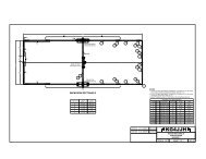
Drawing Sheet 1 presents an overview of the <strong>antenna</strong><br />
assembly. Each component of the <strong>antenna</strong> is identified by a<br />
letter designation (A 0 , A 1 , A 2 , etc). After choosing which version<br />
you want to build, follow the Material Cutting Schedule to<br />
get the correct quantity, material and length. All materials are<br />
easily cut with a tubing cutter, hacksaw or band saw.<br />
After cutting, use a 3 /4 inch countersink bit and a file to deburr<br />
the inside and outside edges of the tubing. Add the common<br />
components (such as channel and stainless steel hardware) and<br />
you will be ready to begin assembly. All of the necessary materials<br />
are listed on Sheet 7 along with sources for each. Figure 2<br />
gives a view of the completed <strong>antenna</strong>, without the mast.<br />
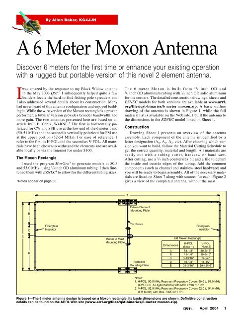
Figure 1—The 6 meter <strong>antenna</strong> design is based on a Moxon rectangle. Its basic dimensions are shown. Definitive construction<br />
details can be found on the ARRL Web site (www.arrl.org/files/qst-binaries/6 meter <strong>moxon</strong>.zip).<br />
April 2004 1
Figure 2—A bottom<br />
view of the completed<br />
<strong>antenna</strong><br />
clearly shows the<br />
fiberglass insulators<br />
separating the driven<br />
element from the<br />
reflector.<br />
Figure 4—A bottom view of the mounting plates. Note the<br />
insulated element support blocks that are discussed in the text.<br />
Figure 5—One of the insulators that separates the reflector<br />
from the driven element.<br />
Figure 3—A top view of the <strong>antenna</strong> mounting plates.<br />
Mounting Plates<br />
The driven element, reflector and boom to mast plates are<br />
fashioned from structural aluminum channel. This material is<br />
overkill for this application, but this method of mounting is<br />
sturdy enough to be used on tubular Moxons up to 20 meters<br />
or more (by scaling the mounts and tubing upward). There is<br />
absolutely no flexing or bending of the mounts and the finished<br />
<strong>antenna</strong> is very solid.<br />
The channel is easily cut with a band saw and a metal cutting<br />
blade. Cut three pieces 8 inches long and lay out all holes<br />
according to the dimensions shown on Sheets 4 through 6. It’s<br />
a good idea to smooth all sharp edges on the channel with a<br />
file. I use a center punch and a drill press with a 1 /16 inch bit to<br />
get accuracy, then go back and enlarge each hole to its final<br />
dimension. Be sure to size the mast saddle clamps to match<br />
your mast and use the chart on the drawing for a drill guide.<br />
Tap the holes as specified and assemble using the stainless<br />
steel saddle clamps and radio support blocks listed. This<br />
was my first encounter with the support blocks and they<br />
provided a great way to support the elements rigidly while<br />
providing isolation from the metal brackets and boom. These<br />
blocks, actually industrial insulated tubing clamps, may also<br />
be found at hydraulic and piping distributors. Figures 3 and 4<br />
show top and bottom views, respectively, of the completed<br />
mounting plates.<br />
Insulators<br />
A pair of insulators that maintain a fixed distance between<br />
2 April 2004<br />
the tubing ends supports the ends of the <strong>antenna</strong> elements<br />
(within dimension C on Drawing Sheet 1). The insulators are<br />
made from 3 /8 inch OD × 10 inch solid fiberglass and slide<br />
inside the 1 /2 inch OD aluminum tubing. Similarly, a 1 /2 inch<br />
OD × 10 inch solid fiberglass rod is used to join the 5 /8 inch<br />
OD tubing at the feed point. (Because tubing and fiberglass<br />
materials are usually sold in 6 foot lengths, the shipping costs<br />
can be more than the material itself. I recommend ordering<br />
enough material for a group of builders to keep the costs down.)<br />
An installed insulator can be seen in Figure 5.<br />
Feed Point<br />
The installation of an SO-239 coax connector on the 6 meter<br />
Moxon adds a bit of reactance to the feed and it is best to<br />
attach the coax directly to the driven element. 5 Unfortunately,<br />
this was not practical for me, as I use this <strong>antenna</strong> for portable<br />
use and prefer to separate the coax from the <strong>antenna</strong>. I tried<br />
several methods and ended up using the channel as a mount<br />
for the SO-239 connector. In the interest of isolating the<br />
feed from the <strong>antenna</strong>, I made an insulator from the end of a<br />
1 1 /2 inch PVC cap and fastened this and the connector to the<br />
channel using nylon screws. Short pieces of 14 gauge insulated<br />
wire connect the SO-239 to the driven element. Apply a<br />
weatherproof sealant to the solder joints. Figure 6 shows the<br />
driven element connection.<br />
An alternate method is to fabricate a bracket that mounts<br />
the SO-239 directly on the driven elements (see Drawing Sheet<br />
7 for details). The brackets are made from 1 1 /2 inch × 1 1 /2 inch<br />
× 1 /8 inch aluminum angle. The connector is mounted on one<br />
bracket, which is attached to one side of the driven element.<br />
Cut the head off of a 6-32 × 1 inch copper screw, file one end<br />
down to fit inside the SO-239 center pin and solder. Use 6-32<br />
nuts on either side to clamp the second bracket, which is attached<br />
to the other side of the driven element. Apply a weatherproof<br />
sealant to the solder joint and copper materials.<br />
Corners<br />
Cut the 3 /8 inch OD aluminum rod into four 8 inch lengths
Figure 8—The<br />
completed 6 meter<br />
Moxon in the<br />
horizontal position.<br />
Figure 6—The driven element SO-239 wiring details. The driven<br />
element can also be wired directly, as outlined in the text.<br />
Figure 7—A corner of<br />
one of the elements.<br />
and chuck each into your drill or drill press. While rotating<br />
the rod, use a file to smooth the edges to ensure a smooth fit<br />
inside 1 /2 inch OD aluminum tubing. The 3 /8 inch OD solid<br />
aluminum rod is fairly soft and easy to bend. My method is to<br />
mark the center and place a scrap piece of 1 /2 inch OD × 12<br />
inch aluminum tubing over each end (to give some leverage)<br />
and slide it near the mark. I then place the 3 /8 inch rod over a<br />
vise-mounted 1 /4 inch drill bit and smoothly push the tubing<br />
down until I have a 90° bend. See Sheet 7 for a corner detail.<br />
A completed corner can be seen in Figure 7.<br />
Fasteners<br />
The 6-32 stainless steel fasteners were chosen to provide<br />
reasonable strength and corrosion resistance without having<br />
to drill very large holes in the tubing. The stop nuts provide a<br />
vibration-proof fastener without using lock washers.<br />
Assembly<br />
I prefer to assemble the <strong>antenna</strong> parts loosely and then go<br />
back and install the fasteners. Mark the center of the 1 /2 inch OD<br />
fiberglass rod (A 0 ) and 1 /8 inch on either side. Slide the fiberglass<br />
inside both pieces of 5 /8 inch OD tubing (A 1 ) up to the 1 /8<br />
inch marks and place inside the radio support blocks on the driven<br />
element mounting bracket. Center the assembly in the bracket<br />
and drill holes and install the feed line screws. Mark the center<br />
of the 5 /8 inch OD aluminum tube (A 3 ) and mount it in the Reflector<br />
Mounting Bracket. Place a line 3 inches from the end on<br />
the four 1 /2 inch OD tubing lengths (A 2 ) and slide each into the<br />
previously mounted 5 /8 inch OD tubing (A 1 and A 3 ) up to the<br />
mark. Place a mark 1 inch from the centerline on each of the<br />
four 3 /8 inch OD bent corners (A 4 ) and insert each inside the 1 /2<br />
inch OD tubing (A 2 ) up to that mark. Mark the centerline and a<br />
point 3 inches from each end on the 3 /8 inch OD fiberglass (C 1 )<br />
and insert each into the 1 /2 inch OD aluminum (B 1 and D 1 ).<br />
At this point you should have a complete <strong>antenna</strong> layout. Referring<br />
to the Moxon dimensional chart, check each ABCDE<br />
measurement and adjust the assembly until you are satisfied.<br />
Keep in mind that there should be at least a 3 inch overlap on all<br />
tubing-to-tubing and rod-to-tubing transitions. When you are sat-<br />
isfied, clamp the tube<br />
positions (I used tape)<br />
and drill straight<br />
through, installing the<br />
stainless steel hardware<br />
as you go. Disassemble<br />
and clean all metal-tometal<br />
joints. Then, apply<br />
an aluminum antioxidant<br />
compound to<br />
the joints to maintain<br />
good electrical contact<br />
by preventing oxidation.<br />
Reassemble and use an<br />
ohmmeter to ensure<br />
feedpoint isolation from<br />
the boom and mounting<br />
brackets.<br />
Antenna Models<br />
H-POL—The resonant<br />
frequency is 50.5<br />
MHz at a height of 15<br />
feet. This <strong>antenna</strong> is<br />
intended to cover the<br />
lower end of the 6 meter<br />
band with less than a<br />
1.3:1 SWR, and tests<br />
conducted with an<br />
MFJ-259B <strong>antenna</strong> analyzer<br />
verified this. The<br />
EZNEC model predicts<br />
the <strong>antenna</strong> to have a<br />
gain of 11 dBi and<br />
front-to-back ratio of 25<br />
dB at resonance. The H-<br />
POL <strong>antenna</strong> completed<br />
and moun-ted is shown<br />
in Figure 8.<br />
Figure 9—The Moxon mounted for<br />
vertical polarization.<br />
V-POL—The resonant frequency is 53 MHz at a height of<br />
15 feet. This <strong>antenna</strong> is intended to cover the upper end of the<br />
6 meter band with less than a 1.6:1 SWR. The EZNEC model<br />
predicts the <strong>antenna</strong> to have a gain of 6.7 dBi and frontto-back<br />
ratio of 36 dB at resonance. The completed V-POL<br />
<strong>antenna</strong> is shown in Figure 9.<br />
April 2004 3
SWR Measurement<br />
Upon completion of the H-POL version, I wanted to compare<br />
the SWR curve predicted by EZNEC with my MFJ-259B<br />
analyzer. At first, I was completely baffled by the results. The<br />
analyzer showed a much broader curve than I thought possible.<br />
W4RNL provided the following explanation:<br />
“If you made the measurements at the end of a length of<br />
coax, they will be flatter than at the <strong>antenna</strong> itself, due to losses<br />
in the coax. These losses increase with thinner coaxes and are<br />
less with 1.2 inch diameter low loss coax cables. Hence, RG-<br />
58/U will show a flatter SWR than some of the latest coax<br />
types. This is normal behavior. As well, the longer the coax<br />
run, the greater the losses and, hence, the flatter the curve. If<br />
you are measuring the low SWR at the <strong>antenna</strong> terminals, then<br />
it becomes more likely that the flat curve is a function of equipment<br />
limitations.”<br />
Armed with this knowledge, I replaced the 50 feet of RG-<br />
8X coax that I had been using with a 3 foot run and got much<br />
better results with the analyzer. Figure 10 shows the <strong>antenna</strong><br />
mounted and ready for testing.<br />
Mounting<br />
The finished <strong>antenna</strong> weighs 8 1 /2 pounds and is light enough<br />
for my trusty painter’s pole at a height of 15 feet. The <strong>antenna</strong><br />
will mount horizontally or vertically by loosening the boom<br />
to mast plate saddle clamps and rotating the <strong>antenna</strong> (see Sheets<br />
2 and 3). If you’re industrious, you could mount the H-POL<br />
and V-POL on the same boom with different feeds. 6<br />
6 Meter Activity<br />
Listen for beacons at the lower end of the band. If you hear<br />
one, chances are the band is open. Here is a short list of where<br />
I have found the most activity:<br />
CW<br />
50.000 to 50.100 MHz<br />
SSB<br />
50.100 to 50.200 MHz<br />
PSK<br />
50.290 MHz<br />
FM 52.000 to 54.000 MHz (simplex and repeaters)<br />
Testing<br />
I decided the best way to test the <strong>antenna</strong> was to go camping<br />
during the July 4 holiday. As luck would have it, tropical<br />
storm Bill was passing through our area, so it was raining<br />
heavily. We set up camp in a light drizzle and then mounted<br />
the Moxon on the painter’s pole. A quick check with NG4T<br />
(about 50 miles away) told me that the <strong>antenna</strong> was working. I<br />
was S7 on his dipole while running 30 W SSB. Our contact<br />
was quickly joined by WB4GBI, who give me a 20 dB over S9<br />
report. It continued to rain throughout the night and the next<br />
day brought some welcome sunshine and NG4T (my brother)<br />
to the campsite. Thanks to an unusual 6 meter opening that<br />
weekend, we logged numerous contacts to California, Colorado<br />
and Texas on SSB and PSK. On FM, 6 meter repeaters<br />
were easily worked with full quieting. I am still on the lookout,<br />
however, for that first 6 meter DX contact!<br />
Results<br />
The <strong>antenna</strong> easily withstood the wet weather and the performance<br />
was flawless, with excellent gain, directivity and<br />
F/B ratio. The fact that the assembled <strong>antenna</strong> is small enough<br />
to fit in a pickup truck makes it a great portable for camping,<br />
Field Day, or an afternoon in the park. So start building—and<br />
discover why 6 meters is called the “Magic Band.”<br />
4 April 2004<br />
Figure 10—A temporary lash-up for testing and adjustment<br />
purposes at the author’s location.<br />
Acknowledgments<br />
I would like to thank L.B. Cebik for his advice and expertise,<br />
my wife Ann for her continued encouragement and support,<br />
and the late Oddis Baker, my father, for his quest for<br />
knowledge that he passed on to me.<br />
Notes<br />
1<br />
A. Baker, <strong>KG4JJH</strong>, “The Black Widow—A Portable 15 Meter Beam,”<br />
QST, May, 2003, pp 35-39.<br />
2<br />
www.cebik.com/<strong>6m</strong>.html.<br />
3<br />
www.qsl.net/ac6la/moxgen.html.<br />
4<br />
www.eznec.com.<br />
5,6<br />
See Note 2.<br />
All photos by the author.<br />
Allen Baker, <strong>KG4JJH</strong>, received his license in September 2000,<br />
after a lifelong dream of becoming a ham. He holds a BS in Industrial<br />
Engineering from Tennessee Technological University and<br />
works as an Instrument and Controls Engineer for the Department<br />
of Energy in Oak Ridge, Tennessee. Allen is active on the<br />
digital modes (6 through 40 meters) and loves to experiment with<br />
<strong>antenna</strong> designs. He can be reached at kg4jjh@arrl.net.