Serial LCD Display Module (PDF) - Basic X
Serial LCD Display Module (PDF) - Basic X
Serial LCD Display Module (PDF) - Basic X

Create successful ePaper yourself
Turn your PDF publications into a flip-book with our unique Google optimized e-Paper software.
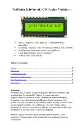
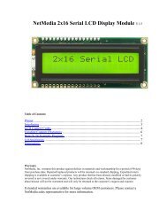
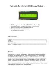
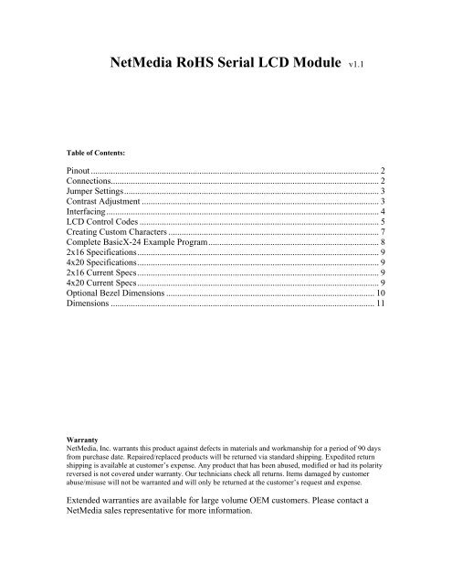
NetMedia RoHS <strong>Serial</strong> <strong>LCD</strong> <strong>Module</strong> v1.1<br />
Table of Contents:<br />
Pinout .................................................................................................................................. 2<br />
Connections......................................................................................................................... 2<br />
Jumper Settings................................................................................................................... 3<br />
Contrast Adjustment ........................................................................................................... 3<br />
Interfacing........................................................................................................................... 4<br />
<strong>LCD</strong> Control Codes ............................................................................................................ 5<br />
Creating Custom Characters ............................................................................................... 7<br />
Complete <strong>Basic</strong>X-24 Example Program............................................................................. 8<br />
2x16 Specifications............................................................................................................. 9<br />
4x20 Specifications............................................................................................................. 9<br />
2x16 Current Specs............................................................................................................. 9<br />
4x20 Current Specs............................................................................................................. 9<br />
Optional Bezel Dimensions .............................................................................................. 10<br />
Dimensions ....................................................................................................................... 11<br />
Warranty<br />
NetMedia, Inc. warrants this product against defects in materials and workmanship for a period of 90 days<br />
from purchase date. Repaired/replaced products will be returned via standard shipping. Expedited return<br />
shipping is available at customer’s expense. Any product that has been abused, modified or had its polarity<br />
reversed is not covered under warranty. Our technicians check all returns. Items damaged by customer<br />
abuse/misuse will not be warranted and will only be returned at the customer’s request and expense.<br />
Extended warranties are available for large volume OEM customers. Please contact a<br />
NetMedia sales representative for more information.
Pinout<br />
All power and communications connections are made via header JP2. Connection JP1 connects the serial module to the<br />
<strong>LCD</strong> header. JP3 contains additional power connectors and user TTL outputs 0 & 1.<br />
Figure1<br />
Connections<br />
JP1 Pins 1 - 8 Description JP1 Pins 9 -16 Description<br />
Pin1 Ground Pin9 D2 (Not Used)<br />
Pin2 VCC (+5) Pin10 D3 (Not Used)<br />
Pin3 Contrast Pin11 D4<br />
Pin4 Data/Command (R/S) Pin12 D5<br />
Pin5 Read/Write (W) Pin13 D6<br />
Pin6 Enable (E1) Pin14 D7<br />
Pin7 D0 (Not Used) Pin15 VCC (LEDSV+)<br />
Pin8 D1 (Not Used) Pin16 Ground<br />
JP2 Pins Description Notes<br />
GND Power Ground Reversing Polarity voids warranty!<br />
+5 Power + 5 supply Tie to +5vdc 15mA+ supply<br />
RX <strong>Serial</strong> Input RS232 or logic level (if used leave RX* disconnected)<br />
RX* <strong>Serial</strong> Input (Inverted) RS232 or logic level (if used leave RX disconnected)<br />
LED+ Backlight Power Tie to 5-14vdc 100mA+ supply<br />
JP3 Pins Description Notes<br />
1 User Output Pin 0<br />
2 User Output Pin 1<br />
3 Power +5 Supply Ties to +5 pin on JP2<br />
4 Power Ground Ties to GND pin on JP2<br />
5 Factory Program Pin DO NOT USE!<br />
2
Jumper Settings<br />
Jumper connections J1 and J2 are used to set the modules baud rate and display type, J3 sets the backlight current.<br />
Note: Always disconnect power before changing jumper positions!<br />
Jumpers J1, J2 & J3<br />
Description<br />
J1<br />
J1 Not Soldered = 9600 Baud, Soldered = 2400 Baud<br />
J2<br />
J2 Not Soldered = 2x16, Soldered = 4x20<br />
J3<br />
Backlight current, Not soldered = 2x16, Soldered = 4x20<br />
Contrast Adjustment<br />
When purchased with an attached <strong>LCD</strong> the contrast is preset at the factory and should not need any major adjustment.<br />
The <strong>LCD</strong> contrast is adjusted using the potentiometer shown in Figure1 (Marked Contrast Pot ). All adjustments must<br />
be made using a plastic potentiometer adjustment tool! Anything else may damage the potentiometer and void your<br />
warranty.<br />
3
Interfacing<br />
The following diagrams show two common methods for interfacing the 2x16 <strong>LCD</strong>.<br />
Connection LEDSV+ is 5-14vdc.<br />
Note: Never connect LED+ to +5 on the BX-24! The BX-24 +5 regulator cannot<br />
supply enough current to power the <strong>LCD</strong> backlight and will overheat.<br />
4
<strong>LCD</strong> Control Codes<br />
Description Keyboard Code ASCII or Decimal value<br />
<strong>Display</strong> custom character 0-7 Ctrl-@ -Through- Ctrl-G 0 - 7<br />
Back Space Ctrl-H 8<br />
Horizontal Tab Ctrl-I 9<br />
New Line Ctrl-J 10<br />
Vertical Tab Ctrl-K 11<br />
Form Feed (Clear Screen) Ctrl-L 12<br />
Carriage Return Ctrl-M 13<br />
Reset Controller Ctrl-N 14<br />
Set Geometry Ctrl-O 15<br />
Set Tab Size Ctrl-P 16<br />
Set Cursor Position Ctrl-Q 17<br />
Set Custom Character *New Command* Ctrl-R 18<br />
Set Contrast Ctrl-S 19<br />
Set Backlight Ctrl-T 20<br />
Command Escape Ctrl-U 21<br />
Data Escape Ctrl-V 22<br />
Raw Data Escape Ctrl-W 23<br />
Toggle TTL Outputs Ctrl-X 24<br />
<strong>Display</strong> an ASCII Character None 25 - 255<br />
Back Space<br />
Ctrl-H<br />
Causes the cursor to move back once space. The cursor will wrap from the first column of a line to the last column of a<br />
previous line. Sending backspace when at the home position causes the cursor to wrap to the last character position of<br />
the last line.<br />
Horizontal Tab<br />
Ctrl-I<br />
Causes the cursor to move forward to the next tab position. If the cursor is near the end of the line and no more tab<br />
positions are on the line, then the cursor will advance to the next line. The <strong>LCD</strong> Controller is initial set up with tab<br />
positions at every 4’th column. To set the tab position at a different column use the “Set Tab Size” command.<br />
New Line<br />
Ctrl-J<br />
Causes the cursor to advance to column 1 of the next line. If the cursor is on the last line, it will wrap to the home<br />
position.<br />
Vertical Tab<br />
Ctrl-K<br />
Causes the cursor to advance to the next line, but stay on the same column. If the cursor is on the last line of the screen,<br />
it will wrap to the first line of the screen.<br />
Form Feed<br />
Ctrl-L<br />
Causes the screen to be cleared and the cursor positioned to the home position. The form feed command takes some<br />
time to complete. It may take up to 2ms to complete. Since the <strong>LCD</strong> Controller has a finite amount of internal buffer<br />
space (16 bytes) for storing commands and data before sending to the <strong>LCD</strong>, you may overrun the internal buffer when<br />
sending multiple form feed commands in succession followed by other data.<br />
5
Carriage Return Ctrl-M<br />
Causes the cursor to go to column 1 of the current line<br />
Reset Controller<br />
Ctrl-N<br />
Resets the <strong>LCD</strong> controller as if it had been just power on. This command will also cause the hardware jumpers to be<br />
reread, so you can use it if you want to change baud rate or display size. This command takes about 1 second to<br />
complete.<br />
Set Geometry<br />
Ctrl-O<br />
Defines the layout (or geometry of the <strong>LCD</strong>). Only use this command for displays other than standard 2x16 or 4x20,<br />
these displays are selected via jumper pad J2. You need to send 5 additional bytes after sending a “Set Geometry”<br />
command.<br />
15+ Number of columns+Line1 starting address+Line2 starting address+Line3 starting address+Lline4 starting<br />
address<br />
Example:<br />
15,20,128,192,148,212 Standard 20 column by 4 line display<br />
15,16,128,192,148,212 Standard 16 column by 4 line display<br />
15,16,128,192,128,128 Standard 16 column by 2 line display<br />
If the display is less than 4 lines then you still need to send the line 1 starting address for the unused starting addresses.<br />
Set Tab Size<br />
Ctrl-P<br />
Sets the size of a tab. You need to send a byte that is the negative of the tab size. The default tab size is 4. The tab size<br />
should be a power of 2 (i.e. 0, 1, 2, 4, 8, 16)<br />
Set Cursor Position<br />
Ctrl-Q<br />
Sets the cursor position. The following 2 bytes specify the zero based row and column of the cursor position. The bytes<br />
need to be within the display range. Sending bytes outside the display range will position the cursor to unpredictable<br />
locations.<br />
Set Custom Character Ctrl-S **** New Command ****<br />
Sets custom character within the <strong>LCD</strong> module. To define a custom character you send a Dec 18 followed by the new<br />
characters address and the eight byte that make up that character. Explained later in this text.<br />
Set Contrast Ctrl-S **** No longer Used ****<br />
Sets the display contrast. The byte following the “Set Contrast” command will set the display contrast. A contrast of 0<br />
is no contrast and a contrast of 255 is full contrast. The contrast is automatically set to 50% at power up.<br />
Set Backlight<br />
Ctrl-T<br />
Sets the display backlight brightness. The byte following the “Set Brightness” command will set the display brightness.<br />
A brightness level of 0 will turn off the backlight completely. A brightness level of 255 is full brightness. At power-up<br />
the brightness is set to 0 or off.<br />
Command Escape<br />
Ctrl-U<br />
The following byte is sent to the <strong>LCD</strong> controller as a raw <strong>LCD</strong> controller command. See the appendix for a list of<br />
commands that the <strong>LCD</strong> controller supports. You will mostly use this command to define custom characters and to set<br />
the cursor shape and visibility.<br />
6
Data Escape<br />
Ctrl-V<br />
The following byte is treated as data. This command is used to send bytes that would normally be interpreted as<br />
commands. Some <strong>LCD</strong> displays (in particular the European font <strong>LCD</strong>s) have characters in the same range as the<br />
commands of the <strong>LCD</strong> controller. This command allows these characters to be sent. After data is output to the <strong>LCD</strong><br />
controller, the cursor is updated properly.<br />
Raw Data Escape<br />
Ctrl-W<br />
The following byte is treated as raw data. This command is used to send bytes that are used for the creation of custom<br />
characters. No attempt is made to advance the cursor since this would interfere with custom character creation.<br />
Toggle TTL Outputs Ctrl-X **** New Command ****<br />
This command sets the state of on-board TTL user outputs. Outputs can sink/source 25mA and can be used for<br />
operating piezo buzzers, relays, LEDs or whatever other device you can come up with. After sending the Ctrl_X byte<br />
the next byte selects the TTL output number (0 or 1) and the last byte selects the state (0 for low and 1 for high). The<br />
<strong>Serial</strong> <strong>LCD</strong> module sets both user outputs to low at power up.<br />
Creating Custom Characters<br />
Creating custom character is an easy way to add missing letters, symbols or characters to your display. Up to 8<br />
characters can be created. A character is added by sending Chr(18) + Chr( RAM Storage Address ) + Character (row<br />
byte) x 8. The RAM Storage address is the location where the character will be stored.<br />
Character RAM StorageAddresses Table<br />
Character Number<br />
Character RAM storage address<br />
0 64 (Dec)<br />
1 72 (Dec)<br />
2 80 (Dec)<br />
3 88 (Dec)<br />
4 96 (Dec)<br />
5 104 (Dec)<br />
6 112 (Dec)<br />
7 120 (Dec)<br />
Calculating Character Row Byte Value<br />
7
Custom Character <strong>Basic</strong>X Code Snippet:<br />
' Load Down Arrow as char 0<br />
Call PutQueueStr(Com3Out,Chr(18) & Chr(64) & Chr(4) & Chr(4) & Chr(4) & Chr(4) & Chr(4) & Chr(31) & Chr(14) & Chr(4))<br />
‘ Print char 0 (new down arrow)<br />
Call PutQueueStr(Com3Out,Chr(0))<br />
Complete <strong>Basic</strong>X-24 Example Program<br />
' This program turns on the <strong>LCD</strong> 2X16 backlight and displays a “Hello World” message.<br />
' Connections:<br />
' <strong>LCD</strong> Gnd to <strong>Basic</strong>X-24 Pin23<br />
' <strong>LCD</strong> +5 to <strong>Basic</strong>X-24<br />
' <strong>LCD</strong> LEDSV+ to <strong>Basic</strong>X-24 Pin24 or 5-12Vdc 150mA + supply<br />
' <strong>LCD</strong> RX to <strong>Basic</strong>X-24 Pin 5<br />
' Define Com3 buffer sizes<br />
Dim Com3In(1 to 15) As Byte<br />
Dim Com3Out(1 to 40) As Byte<br />
' Define the <strong>LCD</strong> control constants we will use<br />
Const BackLite As Byte = 20<br />
Const Clear_<strong>LCD</strong> As Byte = 12<br />
Const Set_Cursor As Byte = 17<br />
'************************************************************<br />
Sub Main()<br />
' Wait 1/2 second after power up for <strong>LCD</strong> to stabilize<br />
Call Sleep(256)<br />
' Open Com3 Buffers<br />
Call OpenQueue(Com3In, 15)<br />
Call OpenQueue(Com3Out, 40)<br />
' Set Com3 to Inverted Logic, 8 Data Bits, No Parity, Pin12 TX, 0 = NO RX pin<br />
Call DefineCom3(0, 5, bx1000_1000)<br />
' Open Com3<br />
Call OpenCom(3, 9600, Com3In, Com3Out)<br />
' Run greeting subroutine<br />
Call Greeting<br />
Do<br />
Loop<br />
'We are done. Sit here and do nothing<br />
End Sub<br />
'************************************************************<br />
Sub Greeting()<br />
' Set backlight to full brightness<br />
Call PutQueueStr(Com3Out,Chr(BackLite) & Chr(255))<br />
' Send Clear <strong>LCD</strong> command and first 1/2 of message "Hello World!"<br />
Call PutQueueStr(Com3Out,Chr(Clear_<strong>LCD</strong>) & " Hello World!")<br />
' Move cursor to Row 2 column 4<br />
Call PutQueueStr(Com3Out,Chr(Set_cursor) & Chr(1) & Chr(3))<br />
' <strong>Display</strong> the rest of the message "I'm Alive!"<br />
Call PutQueueStr(Com3Out,"I'm Alive!")<br />
End Sub<br />
' Return<br />
8
2x16 Specifications<br />
Power ………….4.9-5.2 Vdc @5mA (No Backlight), 135mA (Full Backlight)<br />
<strong>Serial</strong> Input………………8N1, 9600 or 2400 Baud, RS232 or TTL/CMOS level<br />
Maximum Operating Temperature…………………………………….0° - 50° C<br />
4x20 Specifications<br />
Power ………….4.9-5.2 Vdc @5mA (No Backlight), 225mA (Full Backlight)<br />
<strong>Serial</strong> Input………………8N1, 9600 or 2400 Baud, RS232 or TTL/CMOS level<br />
Maximum Operating Temperature…………………………………….0° - 50° C<br />
2x16 Current Specs<br />
Current Usage<br />
Notes<br />
Backlight Off 4.75mA All Colors<br />
Backlight Full On 130mA <strong>LCD</strong> with Blue Backlight<br />
Backlight Full On 66mA <strong>LCD</strong> with Red Backlight<br />
Backlight Full On 66mA <strong>LCD</strong> with Green Backlight<br />
4x20 Current Specs<br />
Current Usage<br />
Notes<br />
Backlight Off 4.75mA All Colors<br />
Backlight Full On 88mA <strong>LCD</strong> with Blue Backlight<br />
Backlight Full On 86mA <strong>LCD</strong> with Red Backlight<br />
Backlight Full On 225mA <strong>LCD</strong> with Green Backlight<br />
9
Optional Bezel Dimensions<br />
10
Dimensions<br />
<strong>Serial</strong> 2x16<br />
<strong>Serial</strong> 4x20<br />
Copyright 2006 by NetMedia, Inc.<br />
10940 N. Stallard Place<br />
Tucson, AZ 85737<br />
(520) 544-4567<br />
11